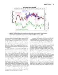
Baird, W.F. and Associates Coastal Engineering Ltd. Detailed Study ...
Baird, W.F. and Associates Coastal Engineering Ltd. Detailed Study ...
Baird, W.F. and Associates Coastal Engineering Ltd. Detailed Study ...

You also want an ePaper? Increase the reach of your titles
YUMPU automatically turns print PDFs into web optimized ePapers that Google loves.
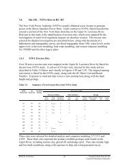
5.2.5 Bypassing Analysis at the Salmon River Jetties<br />
The COSMOS sediment transport estimates were completed with consecutive beach<br />
profiles for ELO to evaluate the influence of changes in the wave climate <strong>and</strong> shoreline<br />
orientation on the direction <strong>and</strong> magnitude of LST. Although this approach is very<br />
effective at assessing regional trends in LST, it can not evaluate the influence of harbors<br />
or jetties, since these structures have a 3D affect on the local wave climate, which can not<br />
be simulated with the 2D beach profile.<br />
Therefore, a 2D hydrodynamic <strong>and</strong> sediment transport model (HYDROSED) was applied<br />
to the Salmon River Jetties to investigate wave propagation, refraction <strong>and</strong> diffraction for<br />
the current morphology at the site. HYDROSED is a state of the art model that consists<br />
of a spectral wave transformation module, where the wave field is calculated by the<br />
spectral energy conservation equation of Karlsson (1969), with the breaking dissipation<br />
term of Isobe, (1987), a hydrodynamic module (Nishimura, 1988) to describe wave<br />
generated nearshore currents <strong>and</strong> circulations (driven by radiation stresses predicted with<br />
the spectral wave transformation module) <strong>and</strong> a sediment transport module presented by<br />
Dibajnia et al (2001). The sediment transport model considers the influence of non-linear<br />
orbital velocities <strong>and</strong> undertow <strong>and</strong> is based on the sheet flow transport formula of<br />
Dibajnia <strong>and</strong> Watanabe (1992), which was extended by Dibajnia (1995) to consider<br />
suspended transport over ripples as well as the bedload transport. Dibajnia et al (2001)<br />
also conducted a sensitivity test <strong>and</strong> showed that the model response under various actual<br />
nearshore wave environments is satisfactory. For a given wave condition, HYDROSED<br />
can provide a full spatial description of nearshore currents <strong>and</strong> s<strong>and</strong> transport within the<br />
model domain. The model has been verified through laboratory experiments as well as<br />
field measurements <strong>and</strong> has been extensively applied to projects by <strong>Baird</strong> & <strong>Associates</strong>.<br />
A map of the lakebed contours in the vicinity of the Salmon River is presented in Figure<br />
5.40, along with the model domain for HYDROSED. The grid was 900 by 600 cells,<br />
with a cell size was 5 m. Therefore, there were 540,000 cells or computations for each<br />
model run.<br />
The spatial extent of the Salmon River Jetties in Figure 5.40 is noted with the black<br />
shading. The tip of the structures only extends to the 2 m depth contour, which is very<br />
shallow for jetties in the Great Lakes.<br />
<strong>Baird</strong> & <strong>Associates</strong> 185 <strong>Detailed</strong> <strong>Study</strong> Sites for the<br />
<strong>Coastal</strong> Performance Indicators
Figure 5.40<br />
Lakebed Contours <strong>and</strong> HYDROSED Model Grid (blue shading)<br />
<strong>Baird</strong> & <strong>Associates</strong> 186 <strong>Detailed</strong> <strong>Study</strong> Sites for the<br />
<strong>Coastal</strong> Performance Indicators
As discussed previously, the first step in predicting sediment bypassing rates at the<br />
harbor is running the nearshore spectral wave module of HYDROSED. Radiation<br />
stresses from this simulation are used as input to the hydrodynamic module to predict<br />
currents <strong>and</strong> general circulation, which is depicted graphically for a 1.0 m wave height<br />
approaching the harbor from 15 degrees south of normal in Figure 5.41.<br />
Figure 5.41<br />
Current Predictions for 1.0 m Wave Height Approaching from 15 Degrees South of<br />
Normal<br />
The current field from the south is very strong at it approaches the south harbor jetty.<br />
There is a slight reduction in the currents along the south jetty. Due to the shallow<br />
depths at the tip of the structure, the increase again as they move past the smaller north<br />
jetty.<br />
<strong>Baird</strong> & <strong>Associates</strong> 187 <strong>Detailed</strong> <strong>Study</strong> Sites for the<br />
<strong>Coastal</strong> Performance Indicators
The resultant current prediction from the hydrodynamic module for a 5.0 m wave height<br />
approaching the jetties from 15 degrees south of normal is summarized graphically in<br />
Figure 5.42. The predicted current field is very large for these big waves. A very strong<br />
bypassing current develops around the tip of the jetty <strong>and</strong> continues in a northerly<br />
direction.<br />
Figure 5.42<br />
Current Predictions for 5.0 m Wave Height Approaching from 15 Degrees South of<br />
Normal<br />
The results from the nearshore spectral wave module <strong>and</strong> the hydrodynamic module are<br />
used to drive the sediment transport predictions in HYDROSED. Figure 5.43 presents a<br />
sample of the model predictions for a range of wave heights (1 to 5 m) approaching the<br />
site from 15 degrees south of normal. A water levels of 0.5 m above Chart Datum was<br />
used for all simulations, which is representative of the conditions during the fall, winter<br />
<strong>and</strong> spring storm season.<br />
The location of the harbor jetties are noted with two vertical black lines in Figure 5.43 (at<br />
2,000 m on the x-axis). The sediment transport rates for a 1 m wave height are very<br />
small. For an input condition of a 2 m wave height, the predicted LST rate is<br />
<strong>Baird</strong> & <strong>Associates</strong> 188 <strong>Detailed</strong> <strong>Study</strong> Sites for the<br />
<strong>Coastal</strong> Performance Indicators
3<br />
approximately 40 m /hr. Plus, the rate of LST does not change significantly from south<br />
to north, suggesting there is full bypassing for this wave condition. Although there is<br />
slightly more variability for the 3, 4 <strong>and</strong> 5 m wave height, the rate of LST moving<br />
towards the jetties is approximately equal to the rate of LST moving north of the jetties<br />
(2,500 to 4,000 on the x-axis).<br />
300<br />
250<br />
200<br />
Alongshore distribution of LST around Salmon River when WL=0.5 m above CD<br />
Wave direction = +15 deg.<br />
H = 5 m<br />
H = 4 m<br />
H = 3 m<br />
H = 2 m<br />
H = 1 m<br />
LST (m 3 /hr)<br />
150<br />
100<br />
50<br />
0<br />
-50<br />
0 1000 2000 3000 4000<br />
Distance alongshore (m)<br />
Figure 5.43<br />
Estimates of Longshore Sediment Transport Across the Model Grid for Waves from<br />
the Southwest (south is represented by 0 on the x-axis, harbor jetties plotted as two<br />
vertical black lines)<br />
Therefore, we can conclude from this series of simulations <strong>and</strong> other similar model runs<br />
that the rate of sediment bypassing from the south to the north is very close to 100%.<br />
To investigate bypassing in a southerly direction at the Salmon River Jetties, a series of<br />
runs were completed for waves approaching from the northwest. The results are plotted<br />
in Figure 5.44. In these examples, the longshore current is moving from 4,500 m on the<br />
x-axis to 0 m. The harbor jetties are located between 2,000 <strong>and</strong> 2,200 m on the x-axis.<br />
<strong>Baird</strong> & <strong>Associates</strong> 189 <strong>Detailed</strong> <strong>Study</strong> Sites for the<br />
<strong>Coastal</strong> Performance Indicators
A very similar trend was observed for the input wave conditions (from 1 to 5 m in height)<br />
as observed for the waves from the south. The jetties have very little affect on the rate of<br />
longshore sediment transport. Therefore, we conclude that waves approaching from the<br />
northwest are able to bypass close to 100% of the incoming sediment.<br />
-250<br />
-200<br />
Alongshore distribution of LST around Salmon River when WL=0.5 m above CD<br />
Wave direction = -5 deg.<br />
H = 5 m<br />
H = 4 m<br />
H = 3 m<br />
H = 2 m<br />
H = 1 m<br />
LST (m 3 /hr)<br />
-150<br />
-100<br />
-50<br />
0<br />
50<br />
0 1000 2000 3000 4000<br />
Distance alongshore (m)<br />
Figure 5.44<br />
Estimates of Longshore Sediment Transport Across the Model Grid for Waves from<br />
the Northwest (south is represented by 0 on the x-axis, jetties at approximately 2,000<br />
to 2,200 m on the x-axis)<br />
In summary, due to the shallow depths at the tip of the Salmon River jetties <strong>and</strong> to a<br />
lesser extent the orientation of these structures, wave generated currents are capable of<br />
bypassing close to 100% of the incoming sediment from the southwest <strong>and</strong> north. It<br />
should be noted that these simulations are based on the 2001 bathymetry. The presence<br />
3<br />
of a south fillet beach, which is estimated at 100,000 to 150,000 m , indicates that the<br />
jetties did initially trap some of the sediment from the south.<br />
<strong>Baird</strong> & <strong>Associates</strong> 190 <strong>Detailed</strong> <strong>Study</strong> Sites for the<br />
<strong>Coastal</strong> Performance Indicators
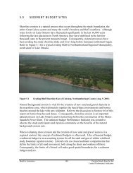
5.2.6 Sediment Budget Findings<br />
The results of the sediment budget calculations are summarized below.<br />
Sediment Sources<br />
Since Eastern Lake Ontario is bounded by two bedrock headl<strong>and</strong>s, new sediment is<br />
3<br />
limited to internal sources. One of the most surprising sources was the 64,000 m /yr<br />
contributed by isostatic rebound <strong>and</strong> erosion of the large s<strong>and</strong> sheet on the lake bed.<br />
Nearshore lakebed <strong>and</strong> beach erosion also contributes some sediment in the center of the<br />
littoral cell. The eroding drumlins <strong>and</strong> glacial till plains contribute some s<strong>and</strong> <strong>and</strong> gravel,<br />
as well as the rounded cobbles <strong>and</strong> pebbles. Historically, prior to the construction of<br />
dams <strong>and</strong> the harbor jetties, the Salmon River may have contributed s<strong>and</strong> to the<br />
lakeshore.<br />
The largest sediment sink quantified in the sediment budget is inlet migration at North<br />
3<br />
Pond. Since the late 1800s, approximately 58,000 m /yr of sediment has accumulated in<br />
the pond. The majority of this sediment is thought to be s<strong>and</strong> on the pond side of the<br />
barrier beach. The southward migration of the inlet at North <strong>and</strong> South Colwell pond is<br />
3 3<br />
responsible for approximately 1 million m of sediment or 8,000 m /yr. Inflation of<br />
younger dune systems <strong>and</strong> accumulation of s<strong>and</strong> in dune blowouts is also a sediment<br />
sink, although the volume is unknown. Finally, the fillet beaches at the Salmon River<br />
Jetties represent a small sink of s<strong>and</strong>.<br />
Wave generated currents transport sediment towards the center of the littoral cell, where<br />
the majority is deposited into North Pond.<br />
5.2.7 Impacts of Lake Level Regulation at ELO<br />
It is difficult to quantify the impacts of water level regulation at Eastern Lake Ontario,<br />
since the site features a combination of dynamic natural areas <strong>and</strong> heavily altered<br />
shoreline due to home construction <strong>and</strong> engineering protection structures. For example,<br />
as discussed in Section 6.2, the occasion high lake period <strong>and</strong> associated embryo dune<br />
erosion would maximize the health of the dune grasses at ELO <strong>and</strong> ensure these<br />
vegetation communities don’t stabilize or reach a point of senescence. However, high<br />
lake levels <strong>and</strong> erosion will eventually lead to more shoreline protection structures for the<br />
homes constructed on the dunes.<br />
Another threat of high lake levels is the potential for the present inlet to close <strong>and</strong> a new<br />
inlet to develop, possible to the north of the present location. Such an event would lead<br />
to another significant period of sedimentation in North Pond, which is the major sediment<br />
<strong>Baird</strong> & <strong>Associates</strong> 191 <strong>Detailed</strong> <strong>Study</strong> Sites for the<br />
<strong>Coastal</strong> Performance Indicators
sink at Eastern Lake Ontario. Therefore, from an inlet stability <strong>and</strong> sediment budget<br />
st<strong>and</strong>point, avoiding high lake levels is recommended.<br />
Low lakes would also be beneficial, as beaches would recover naturally <strong>and</strong> aeolian<br />
processes could build new embryo dunes. In addition, during periods of low lake levels,<br />
the lakebed profile will be out of equilibrium with the wave climate, leading to the<br />
onshore transport of s<strong>and</strong>. This process is similar to the long term impacts of isostatic<br />
rebound, only it would occur much quicker.<br />
<strong>Baird</strong> & <strong>Associates</strong> 192 <strong>Detailed</strong> <strong>Study</strong> Sites for the<br />
<strong>Coastal</strong> Performance Indicators
6.0 BARRIER BEACHES AND DUNES<br />
Section 6.0 of the report will review the studies completed for the barrier beaches <strong>and</strong><br />
dunes Performance Indicator. The history of the former barrier at Braddock’s Bay will<br />
be reviewed, plus shoreline change measurements <strong>and</strong> computer modeling will be<br />
summarized at the study sites to highlight the impacts of lake levels on dune erosion.<br />
6.1 Braddock’s Bay Barrier Beach Case <strong>Study</strong><br />
Braddock Bay is located in Greece, New York on the south shore of Lake Ontario. The<br />
community of Greece is located west of the Genesee River <strong>and</strong> north of Rochester, in<br />
Monroe County. Figure 6.1 presents an old map of the area dated 1902. Historically, the<br />
bay was separated from Lake Ontario by a s<strong>and</strong>y barrier beach.<br />
Figure 6.1<br />
1902 Map of Braddock Bay (Tomkiewicz <strong>and</strong> Husted)<br />
<strong>Baird</strong> & <strong>Associates</strong> 193 <strong>Detailed</strong> <strong>Study</strong> Sites for the<br />
<strong>Coastal</strong> Performance Indicators
With the industrialization of the Rochester economy in the late 1800s <strong>and</strong> early 1900s,<br />
the growing population of Monroe County was looking for exp<strong>and</strong>ed access to<br />
recreational opportunities on Lake Ontario. Cottage developments were constructed<br />
along the lake, as depicted in the historical photograph in Figure 6.2.<br />
Figure 6.2<br />
Cottage Development along Lake Shore, near Rochester NY (Tomkiewicz <strong>and</strong><br />
Husted)<br />
In addition to the cottage development, a rail link from Rochester to Greece was<br />
constructed to bring vacationers to the lakefront. The line continued along the lakeshore,<br />
including a link across the Braddock Bay barrier to reach the community of Manitou<br />
Beach. A picture of the old trolley is presented in Figure 6.3.<br />
Figure 6.3<br />
Manitou Beach Trolley (Tomkiewicz <strong>and</strong> Husted)<br />
A trestle was used to cross the inlet to the bay <strong>and</strong> reach Manitou Beach (refer to the map<br />
in Figure 6.1 <strong>and</strong> picture in 6.4). As the barrier beach started to erode in the early 1900s,<br />
<strong>Baird</strong> & <strong>Associates</strong> 194 <strong>Detailed</strong> <strong>Study</strong> Sites for the<br />
<strong>Coastal</strong> Performance Indicators
the size the inlet increased <strong>and</strong> the exposure of the trestle to lake storms increased. It was<br />
rebuilt further inl<strong>and</strong> but eventually ab<strong>and</strong>oned.<br />
Figure 6.4<br />
Manitou Beach Trolley (Tomkiewicz <strong>and</strong> Husted)<br />
A series of old maps chronicle the history of the barrier <strong>and</strong> the development of the<br />
waterfront. They were scanned <strong>and</strong> geo-referenced in GIS to align with the 1995<br />
orthophotograph. Although these old maps were often only sketches of the historical<br />
l<strong>and</strong>scape <strong>and</strong> not based on traditional l<strong>and</strong> surveying techniques, they captured the<br />
beach conditions between 1811 <strong>and</strong> 1925, a period when modern mapping was not<br />
available. These historical maps were overlaid with the modern 1998 orthophotograph in<br />
a series of map panels in Figure 6.5. The linework from the historical maps is presented<br />
in yellow to provide contrast.<br />
In 1811 Braddock Bay was completely sheltered from Lake Ontario by the barrier beach<br />
<strong>and</strong> only featured a small inlet. The 1852 map depicts a similar condition. In 1872 a<br />
barrier beach also protected the bay <strong>and</strong> sheltered the marsh community. The inlet<br />
appears to have migrated northwest towards Manitou Beach. The 1902 map, which was<br />
presented earlier in Figure 6.1, depicts a large inlet into Braddock Bay <strong>and</strong> is the first<br />
time the rail line is depicted on the old maps. By 1928, the barrier beach only protects<br />
approximately half of the bay.<br />
In Figure 6.6, a series of aerial photographs were registered from 1958 to 2001. In 1958<br />
<strong>and</strong> 1966, the western arm of the former barrier was about 500 m in length <strong>and</strong> still<br />
featured a somewhat natural morphology. By 1978 the western arm had retreated back to<br />
the perimeter of the bay, where it has remained for the last three decades.<br />
By 1958 the eastern arm of the barrier had decreased to approximately 200 m in length<br />
<strong>and</strong> was migrating into the bay. By 1966, the remaining portion of the eastern barrier had<br />
been anchored in place with shoreline protection to shelter a marina (SE corner).<br />
<strong>Baird</strong> & <strong>Associates</strong> 195 <strong>Detailed</strong> <strong>Study</strong> Sites for the<br />
<strong>Coastal</strong> Performance Indicators
Figure 6.5<br />
Braddock Bay, Monroe County, South Shore of Lake Ontario from 1811 to 1928 (Old Maps from Tomkiewicz <strong>and</strong> Husted)<br />
<strong>Baird</strong> & <strong>Associates</strong> 196 <strong>Detailed</strong> <strong>Study</strong> Sites for the<br />
<strong>Coastal</strong> Performance Indicators
Figure 6.6 Braddock Bay, Monroe County, South Shore of Lake Ontario from 1958 to 2001<br />
<strong>Baird</strong> & <strong>Associates</strong> 197 <strong>Detailed</strong> <strong>Study</strong> Sites for the<br />
<strong>Coastal</strong> Performance Indicators
A comprehensive study was not completed to quantify the factors that contributed to the<br />
slow demise of the Braddock Bay barrier beach. However, based on the data presented<br />
above <strong>and</strong> several site visits to the area, the following probable factors are identified: 1)<br />
disruption of the natural barrier beach <strong>and</strong> dune system with the construction of homes,<br />
roadways <strong>and</strong> rail lines along the shoreline, 2) reduction in the supply of new s<strong>and</strong> <strong>and</strong><br />
gravel due to the construction of shoreline protection, 3) interruption of the natural<br />
patterns of longshore sediment transport due to harbour structures on the south shore of<br />
Lake Ontario. The relative contribution of these three factors to the ultimate demise of<br />
the barrier is not known.<br />
<strong>Baird</strong> & <strong>Associates</strong> 198 <strong>Detailed</strong> <strong>Study</strong> Sites for the<br />
<strong>Coastal</strong> Performance Indicators
6.2 Site #13 – North Pond Barrier Beach, Eastern Lake Ontario<br />
North Pond is sheltered from Lake Ontario by a large barrier beach with a dynamic<br />
migrating inlet. Refer to the orthophotograph <strong>and</strong> bathymetry in Figure 6.7.<br />
Figure 6.7<br />
North Pond Barrier Beach, Eastern Lake Ontario<br />
<strong>Baird</strong> & <strong>Associates</strong> 199 <strong>Detailed</strong> <strong>Study</strong> Sites for the<br />
<strong>Coastal</strong> Performance Indicators
The barrier beach is approximately 6 km in length <strong>and</strong> features large relic coastal dunes<br />
in some locations, while aeolian processes are re-building new dunes in others. <strong>Detailed</strong><br />
computer modeling was completed at two locations along the North Pond barrier beach in<br />
conjunction with the species at risk group of the Environmental Technical Working<br />
Group (ETWG). There was three primary objectives: 1) investigate the impacts of lake<br />
levels <strong>and</strong> storms on beach <strong>and</strong> dune erosion at the two sites, 2) interpret the impacts of<br />
these erosion events on three endangered plant species found on the barriers at ELO,<br />
including ammophila champlainensis, Prunus pumila var. pumila <strong>and</strong> Salix cordata, <strong>and</strong><br />
make recommendations for a future regulation plan that will enhance the conditions for<br />
these three endangered plant species. These plant species, which collectively will be<br />
referred to as beach grass, are listed as endangered by the NY State Department of<br />
Environmental Conservation.<br />
6.1.1 Wave Climate<br />
The storm conditions offshore of North Pond were assessed based on the 1961 to 2000<br />
wave climate at Station 2995. All the storms were selected from the hourly data that<br />
featured wave heights in excess of 2.0 m for a minimum of 6.0 hours. A total of 344<br />
storms were identified <strong>and</strong> summarized in Figure 6.8 based on the month of occurrence.<br />
This analysis considers the historical ice conditions, which reduces the number of events<br />
in February <strong>and</strong> March.<br />
100<br />
80<br />
# of Storm Events<br />
60<br />
40<br />
20<br />
0<br />
Jan Feb Mar Apr May June July Aug Sep Oct Nov Dec<br />
Month<br />
Figure 6.8<br />
Storm Climate Offshore of North Pond at 10 m Depth Contour (1961 to 2000 waves,<br />
344 events)<br />
<strong>Baird</strong> & <strong>Associates</strong> 200 <strong>Detailed</strong> <strong>Study</strong> Sites for the<br />
<strong>Coastal</strong> Performance Indicators
The fall, winter <strong>and</strong> spring periods are clearly the stormiest at the Eastern Lake Ontario<br />
site. However, these storms also occur when the lake levels are near the low point of the<br />
seasonal cycle, not the summer peak. Therefore, the storm selection was further analyzed<br />
to select storm events that occur during the summer months. Two storms were selected<br />
for the analysis of dune erosion, July 5-7, 1973 <strong>and</strong> August 13-17, 1979, as summarized<br />
in Table 6.1 below.<br />
Table 6.1<br />
Wave Conditions for Two Historical Storms at ELO (conditions at 10 m depth<br />
contour)<br />
Date<br />
July 5-7, 1973<br />
August 13-16, 1979<br />
Duration<br />
(hours)<br />
Direction<br />
(deg)<br />
Peak Height<br />
(m)<br />
61 ~260 1.83 6.4<br />
97 ~270 2.27 7.85<br />
Peak Period<br />
(s)<br />
6.2.2 Beach <strong>and</strong> Dune Profiles<br />
Two sites along the North S<strong>and</strong>y Pond barrier beach were selected, one south of the<br />
current inlet (Photo 2080) <strong>and</strong> one north of the inlet (Photo 2086). Refer to Figure 6.9.<br />
Figure 6.9 Plan View of Profile Location for Photo 2080 <strong>and</strong> 2086<br />
<strong>Baird</strong> & <strong>Associates</strong> 201 <strong>Detailed</strong> <strong>Study</strong> Sites for the<br />
<strong>Coastal</strong> Performance Indicators
Oblique aerial photographs of the two sites taken on August 6, 2003 are presented in<br />
Figures 6.10 <strong>and</strong> 6.11 for reference. Photo 2080 is the location of the former inlet <strong>and</strong><br />
features an active embryo dune covered in dune grasses. The primary dune ride <strong>and</strong> a<br />
secondary ridge that marked the boundary of the former inlet are now vegetated with<br />
pioneer shrub <strong>and</strong> tree species. Photo 2086 captures the barrier conditions at a very<br />
susceptible location adjacent to an older relic dune, which is eroding. The barrier ridge is<br />
very narrow, low crested <strong>and</strong> generally devoid of vegetation.<br />
PROFILE<br />
Figure 6.10 Location of Profile for Photo 2080<br />
PROFILE<br />
Figure 6.11 Location of Profile for Photo 2086<br />
<strong>Baird</strong> & <strong>Associates</strong> 202 <strong>Detailed</strong> <strong>Study</strong> Sites for the<br />
<strong>Coastal</strong> Performance Indicators
The COSMOS model was used to simulate cross-shore profile response for the two storm<br />
events at a range of water levels. The results for the average summer storm (July 5,<br />
1973) <strong>and</strong> a lake level of 1.0 m are presented below in Figure 6.12. The input profile, as<br />
captured by the detailed LIDAR bathymetry <strong>and</strong> topography for the site, is depicted in<br />
Figure 6.12, along with the zone of active dune grass vegetation. The storm resulted in<br />
some beach erosion, however, this zone was limited to the profile below the beach grass.<br />
5<br />
Elevation (m above CD, 74.2 m IGLD'85)<br />
4<br />
3<br />
2<br />
1<br />
0<br />
-1<br />
-2<br />
Post-Storm Profile<br />
Pre-storm Profile<br />
Zone of Ammophila<br />
Lake Level<br />
-3<br />
1350 1400 1450 1500 1550 1600 1650<br />
Distance (m)<br />
Figure 6.12<br />
Profile 2080 Response to Average Summer Storm at 75.2 m (1.0 m above CD)<br />
The average summer storm was re-run for Profile 2080 with a lake level of 75.7 m (1.5 m<br />
above CD). The results are presented in Figure 6.13. It is worth noting that this is an<br />
extreme high summer water level that has only occurred on a few occasions since Lake<br />
Ontario regulation began in 1960.<br />
Elevation (m above CD, 74.2 m IGLD'85)<br />
5<br />
4<br />
3<br />
2<br />
1<br />
0<br />
-1<br />
-2<br />
Pre-storm Profile<br />
Post-Storm Profile<br />
Zone of Ammophila<br />
Lake Level<br />
-3<br />
1350 1400 1450 1500 1550 1600 1650<br />
Distance (m)<br />
Figure 6.13<br />
Profile 2080 Response to Average Summer Storm at 75.7 m (1.5 m above CD)<br />
<strong>Baird</strong> & <strong>Associates</strong> 203 <strong>Detailed</strong> <strong>Study</strong> Sites for the<br />
<strong>Coastal</strong> Performance Indicators
A 10 m wide zone of the dune grass on the embryo dune is eroded for the simulation that<br />
assumes an average summer storm occurs at a very high summer lake level. The erosion<br />
scarp on the dune extends up to the 3 m contour. The event would disrupt the dune grass<br />
community <strong>and</strong> eliminate the late successional stage that can occur with storm exposure<br />
at the toe of the dunes.<br />
The profile response simulations were repeated with the COSMOS model at Profiles<br />
2080 <strong>and</strong> 2086 for the severe summer storm that occurred on August 13, 1979. The<br />
results at Profile 2080 for a lake level of 75.2 m (1.0 m above CD) are presented in<br />
Figure 6.14. Significant beach <strong>and</strong> dune erosion was predicted with the model, including<br />
disruption of the dune grass community.<br />
5<br />
Elevation (m, IGLD'85)<br />
4<br />
3<br />
2<br />
1<br />
0<br />
-1<br />
-2<br />
Post_Storm Profile<br />
Pre-Storm Profile<br />
Zone of Ammophila<br />
Lake Level<br />
-3<br />
1350 1400 1450 1500 1550 1600 1650<br />
Distance offshore (m)<br />
Figure 6.14<br />
Profile 2080 Response to Severe Summer Storm at 75.2 m (1.0 m above CD)<br />
The severe summer storm was re-run for Profile 2080 assuming a high summer lake level<br />
of 75.7 m. Refer to results in Figure 6.15. Significant beach <strong>and</strong> dune erosion is<br />
predicted across a 50 m zone for Profile 2080. Dune erosion is predicted up to the crest<br />
of the primary dune 4.5 m above Chart Datum. The entire beach grass community would<br />
be disrupted.<br />
The COSMOS prediction for a severe summer storm at Profile 2086 with a summer lake<br />
level of 75.7 m is presented in Figure 6.16. For this narrow <strong>and</strong> low crested portion of<br />
the barrier beach, the model predicts wave overtopping <strong>and</strong> erosion of the entire dune<br />
profile. These results must be interpreted within the context of the model functionality.<br />
For example, predicting the precise dune erosion response <strong>and</strong> wave overwash processes<br />
with a computer model such as COSMOS is difficult. However, a few important<br />
observations can be made. First, wave runup <strong>and</strong> overtopping may occur during severe<br />
summer storms at high summer lake levels. Although this type of event will disrupt the<br />
dune grass communities, which is desired to avoid dune stabilization <strong>and</strong> a late<br />
successional stage for the vegetation, there is a very series risk of a breach in the barrier<br />
<strong>Baird</strong> & <strong>Associates</strong> 204 <strong>Detailed</strong> <strong>Study</strong> Sites for the<br />
<strong>Coastal</strong> Performance Indicators
each during severe storms at high lake levels. Locations such as Profile 2086 are<br />
particularly susceptible since the beach is narrow <strong>and</strong> the dune ride is low crested.<br />
Elevation (m, IGLD'85)<br />
5<br />
4<br />
3<br />
2<br />
1<br />
0<br />
-1<br />
Post_Storm Profile<br />
Pre-Storm Profile<br />
Zone of Ammophila<br />
Lake Level<br />
-2<br />
-3<br />
1350 1400 1450 1500 1550 1600 1650<br />
Distance offshore (m)<br />
Figure 6.15<br />
Profile 2080 Response to Severe Summer Storm at 75.7 m (1.5 m above CD)<br />
Elevation (m above CD, 74.2 m IGLD'85)<br />
5<br />
4<br />
3<br />
2<br />
1<br />
0<br />
-1<br />
-2<br />
Pre-Storm Profile<br />
Post_Storm Profile<br />
Lake Level<br />
-3<br />
1400 1450 1500 1550 1600 1650 1700<br />
Distance (m)<br />
Figure 6.16<br />
Profile 2086 Response to Severe Summer Storm at 75.7 m (1.5 m above CD)<br />
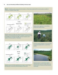
In summary, the barrier beach at Eastern Lake Ontario is a dynamic s<strong>and</strong>y geomorphic<br />
feature. Beach erosion <strong>and</strong> recovery is a natural process, as is inlet migration. An<br />
environment that is constantly changing ensures the vegetation communities, particularly<br />
the endangered dune grasses, will remain healthy <strong>and</strong> avoid a condition of dune<br />
stabilization or a late successional stage, also known as senescence. The computer<br />
<strong>Baird</strong> & <strong>Associates</strong> 205 <strong>Detailed</strong> <strong>Study</strong> Sites for the<br />
<strong>Coastal</strong> Performance Indicators
modeling of beach <strong>and</strong> dune response to Lake Ontario storms indicates that occasionally<br />
the combination of higher than average summer conditions <strong>and</strong> storms would provide the<br />
necessary disruption to the dune grass communities to ensure they don’t stabilize.<br />
However, this objective is ad odds with the current development pattern along Eastern<br />
Lake Ontario, which has permitted the construction of homes in the dynamic <strong>and</strong> fragile<br />
dune environment. In some locations, homes <strong>and</strong> cottages are build right on top of the<br />
dunes. In these locations, it will be very difficult to achieve the desired disruption of the<br />
dune grass communities without threatening capital investments in homes <strong>and</strong> cottages.<br />
In addition, these types of storms often lead to the construction of shoreline protection,<br />
which further disrupts the natural system <strong>and</strong> reduces the supply of new s<strong>and</strong> threw<br />
natural background erosion.<br />
For additional details on the assessment of dune erosion <strong>and</strong> impacts on dune grass<br />
communities, refer to the ETWG report (2004) entitled “Water Level Regulation Impacts<br />
on Endangered Dune Species.”<br />
<strong>Baird</strong> & <strong>Associates</strong> 206 <strong>Detailed</strong> <strong>Study</strong> Sites for the<br />
<strong>Coastal</strong> Performance Indicators
6.3 Site #14 – North <strong>and</strong> South Colwell Pond, Eastern Lake Ontario<br />
North <strong>and</strong> South Colwell Pond are located within the Eastern Lake Ontario barrier beach<br />
complex, north of the S<strong>and</strong>y Pond Site. The barrier beach is almost 300 wide in some<br />
locations <strong>and</strong> supports a large dune complex. The inlet is presently at the southern end of<br />
South Colwell Pond, as depicted in Figure 6.17.<br />
Figure 6.17 <strong>Study</strong> Site #14<br />
Oblique digital photographs of the site where collected on August 6, 2003. A view of the<br />
inlet to South Colwell Pond is provided in Figure 6.18. A submerged channel in the<br />
lakebed is observed through the s<strong>and</strong>y nearshore zone. Also, the wide <strong>and</strong> vegetated<br />
barrier ridge is seen to the north of the inlet.<br />
This is a dynamic environment <strong>and</strong> the inlet is occasionally closed due to sedimentation<br />
from the lake, as observed on April 12, 2002. Refer to Figure 6.19. By the time of the<br />
August 2003 oblique aerials, the channel had re-opened. This type of channel is<br />
classified as an ephemeral inlet.<br />
<strong>Baird</strong> & <strong>Associates</strong> 207 <strong>Detailed</strong> <strong>Study</strong> Sites for the<br />
<strong>Coastal</strong> Performance Indicators
Figure 6.18 Inlet to South Colwell Pond, August 6, 2003<br />
Figure 6.19 Inlet to South Colwell Pond Temporarily Closed, April 12, 2002<br />
The wide barrier ridge <strong>and</strong> channel between North <strong>and</strong> South Colwell Pond is presented<br />
in Figure 6.20. Successive dune ridges are not visible in the orthophotograph, suggesting<br />
some processes other than a progradational shoreline has built this wide stable barrier<br />
ridge.<br />
<strong>Baird</strong> & <strong>Associates</strong> 208 <strong>Detailed</strong> <strong>Study</strong> Sites for the<br />
<strong>Coastal</strong> Performance Indicators
Figure 6.20 Barrier Ridge <strong>and</strong> Channel Between North <strong>and</strong> South Colwell Pond, August 6, 2003<br />
A series of historical maps <strong>and</strong> aerial photographs of the sites was used to evaluate the<br />
geomorphic formation <strong>and</strong> evolution of this barrier beach. Refer to Figure 6.21 for<br />
images of the barrier from 1878, 1893, 1974, 1983 <strong>and</strong> 1998.<br />
In 1878, there was only a partial barrier <strong>and</strong> a series of small isl<strong>and</strong>s protecting North<br />
Colwell Pond. The barrier beach was continuous along South Colwell Pond but<br />
considerably narrower than the modern condition. The beach <strong>and</strong> pond conditions<br />
identified on the 1893 map were very similar to 1878. There is a large gap between the<br />
next available data, 1974, which documents a mature <strong>and</strong> wide barrier ridge, with the<br />
inlet slightly north of the present location. In 1983, the mouth of the inlet was closed,<br />
similar to the conditions documented in the spring of 2002. The location <strong>and</strong><br />
morphology of the inlet has not changed significantly between 1983 <strong>and</strong> 1998. In<br />
summary, in the late 1800s, North Colwell Pond was open to Lake Ontario. In the 100<br />
years following the old maps to the 1974 condition, it appears the inlet migrated<br />
southward to its present location adjacent to Montario Point <strong>and</strong> a wide barrier has<br />
formed.<br />
One possible explanation for the formation of the wide barrier beach fronting North <strong>and</strong><br />
South Colwell Pond is a southward migrating inlet. As the inlet migrated south, the old<br />
channels filled with sediment <strong>and</strong> ultimately aeolian transport created the modern dune<br />
l<strong>and</strong>scape. When the terminus of the current inlet in the pond is observed, the<br />
morphology of the s<strong>and</strong> ridges provides some possible clues to support this hypothesis.<br />
If this inlet filled with sediment, ultimately the two terminal s<strong>and</strong> ridges would merge <strong>and</strong><br />
<strong>Baird</strong> & <strong>Associates</strong> 209 <strong>Detailed</strong> <strong>Study</strong> Sites for the<br />
<strong>Coastal</strong> Performance Indicators
create a rounded promontory into South Colwell Pond. When the backside of the barrier<br />
is examined in Figure 6.17, similar rounded promontories can be observed.<br />
<strong>Baird</strong> & <strong>Associates</strong> 210 <strong>Detailed</strong> <strong>Study</strong> Sites for the<br />
<strong>Coastal</strong> Performance Indicators
Figure 6.21 History of Barrier Ridge Growth <strong>and</strong> Migration at North <strong>and</strong> South Colwell Pond, 1878 to 1998<br />
<strong>Baird</strong> & <strong>Associates</strong> 211 <strong>Detailed</strong> <strong>Study</strong> Sites for the<br />
<strong>Coastal</strong> Performance Indicators
The impacts of lake level regulation was not investigated with computer models at North<br />
<strong>and</strong> South Colwell Pond. However, the results from North S<strong>and</strong>y Pond, which is located<br />
a few kilometers to the south, can be interpreted for <strong>Study</strong> Site #14. First, the absence of<br />
shoreline development, such as houses <strong>and</strong> roads, will permit this beach <strong>and</strong> dune<br />
environment to respond dynamically to erosion <strong>and</strong> sedimentation events. Even the most<br />
extreme prediction of beach <strong>and</strong> dune erosion for a severe summer storm at high lake<br />
levels would not have a lasting negative impact on the site, since the barrier beach is very<br />
wide <strong>and</strong> it could recover during low <strong>and</strong> average water level conditions.<br />
A typical view of the barrier beach fronting the ponds is presented in Figure 6.22. The<br />
image was taking in April 2002 <strong>and</strong> thus it is difficult to evaluate the presence or absence<br />
of dune grasses, such as those listed as endangered by the NYS DEC. However, the<br />
abundance of mature deciduous trees along the foredune ridge suggest the beach <strong>and</strong><br />
dune system has been stable over the last several decades.<br />
Figure 6.22<br />
Typical View of the Beach <strong>and</strong> Dune Fronting North <strong>and</strong> South Colwell Pond, April<br />
12, 2002<br />
If the southward migrating inlet theory is correct, it appears the channel is close to or has<br />
reached it southern maximum, since Montario Point now anchors this feature to the<br />
south. Therefore, it is possible the inlet could fill in during a large sedimentation event<br />
<strong>and</strong> never re-open. Or at least re-open in a different location, likely the northern corner<br />
of North Colwell Pond.<br />
<strong>Baird</strong> & <strong>Associates</strong> 212 <strong>Detailed</strong> <strong>Study</strong> Sites for the<br />
<strong>Coastal</strong> Performance Indicators
6.4 Site #15 – Huyck’s Bay Barrier Beach<br />
Huyck’s Bay Barrier Beach is located on the south shore of Prince Edward County,<br />
between Presqu’ile Point <strong>and</strong> the community of Wellington. A site map of the bay,<br />
which features partial orthophotograph coverage, is presented in Figure 6.23. The MNR<br />
general lakewide depth contours are also plotted for reference. There was no detailed<br />
SHOALS data collected for this site.<br />
Figure 6.23<br />
<strong>Study</strong> Site #15, Huyck’s Bay<br />
<strong>Baird</strong> & <strong>Associates</strong> 213 <strong>Detailed</strong> <strong>Study</strong> Sites for the<br />
<strong>Coastal</strong> Performance Indicators
Huyck’s Bay is sheltered from Lake Ontario by a narrow s<strong>and</strong> <strong>and</strong> gravel barrier beach,<br />
as seen in Figure 6.23. The barrier beach is anchored on the north <strong>and</strong> south by two<br />
limestone headl<strong>and</strong>s <strong>and</strong> thus functions similar to a large pocket beach. A series of<br />
photographs are presented to document the site conditions on September 15, 2002.<br />
The headl<strong>and</strong> that anchors the pocket beach to the south features shelving bedrock at the<br />
tip, eroding limestone banks <strong>and</strong> is heavily vegetated. Refer to Figure 6.24. At the actual<br />
point in the shoreline, there is not beach material. Closer to the actual barrier beach, the<br />
beach consists of large slabs of limestone, then progressively grades to smaller pieces of<br />
shingle, cobbles <strong>and</strong> s<strong>and</strong>. All of this material is eroded locally from the bank.<br />
Figure 6.24 Eroding Limestone Headl<strong>and</strong> at South End of Huyck’s Bay, Sept. 15, 2002<br />
A view of the limestone beds in the eroding bank is presented in Figure 6.25. The water<br />
bottle is sitting on a<br />
large slab of limestone,<br />
while the layers above<br />
feature smaller<br />
fractured pieces of rock<br />
that will eventually<br />
become washed shingle<br />
on the beach. The<br />
limestone is capped<br />
with a thin soil<br />
horizon.<br />
Figure 6.25 Close-up of Eroding Limestone Bank, Huyck’s Bay, Sept. 15, 2002<br />
<strong>Baird</strong> & <strong>Associates</strong> 214 <strong>Detailed</strong> <strong>Study</strong> Sites for the<br />
<strong>Coastal</strong> Performance Indicators
At the southeast corner of the bay, the beach transitions from slabs of limestone <strong>and</strong><br />
shingle to cobbles <strong>and</strong> pebbles, as seen in Figure 6.26. The marsh conditions behind at<br />
barrier beach are presented in Figure 6.27.<br />
Figure 6.26<br />
<strong>Study</strong> Site #15, Huyck’s Bay<br />
Figure 6.27 Huyck’s Bay Marsh, Looking Northeast, Sept. 15, 2002<br />
At the time of the site visit, the current inlet to Huyck’s Bay was closed with a wide<br />
gravel bar. Refer to Figure 6.28. Although this bar separates <strong>and</strong> shelters the marsh from<br />
lake waves, it is very porous <strong>and</strong> water was observed draining through the gravel bar.<br />
For example, a pool of water above lake level was observed <strong>and</strong> featured a cascading<br />
flow of water across the cobbles <strong>and</strong> pebbles. A picture is provided in Figure 6.29.<br />
<strong>Baird</strong> & <strong>Associates</strong> 215 <strong>Detailed</strong> <strong>Study</strong> Sites for the<br />
<strong>Coastal</strong> Performance Indicators
Figure 6.28<br />
Gravel Bar Across the Mouth of Huyck’s Bay<br />
Figure 6.29<br />
Bay Water Draining Through the Gravel Bar due to Hydraulic Head<br />
The middle of the barrier beach is s<strong>and</strong>y with scattered deposits of shingle <strong>and</strong> gravel.<br />
Small patches of dune grasses were observed, along with shrubs <strong>and</strong> deciduous trees. A<br />
very small erosion scarp was observed but overall site observations suggested the barrier<br />
beach was stable. Refer to Figure 6.30.<br />
<strong>Baird</strong> & <strong>Associates</strong> 216 <strong>Detailed</strong> <strong>Study</strong> Sites for the<br />
<strong>Coastal</strong> Performance Indicators
Figure 6.30<br />
Center of Barrier Beach Features a S<strong>and</strong> Beach with Isolated Shingle<br />
Near the northwest corner of the bay, the shelving bedrock re-appears at the waterline. A<br />
typical view of the limestone bedrock is presented in Figure 6.31. Based on a review of<br />
the lake bottom contours in Figure 6.23, it appears this bedrock extends below the lake<br />
surface in a prominent ridge or shoal. If this bedrock high extends inl<strong>and</strong>, it may also<br />
explain the topographic separation between the two interior marshes.<br />
Figure 6.31<br />
Shelving Bedrock at the Waterline in the Northwest Corner of the Bay<br />
<strong>Baird</strong> & <strong>Associates</strong> 217 <strong>Detailed</strong> <strong>Study</strong> Sites for the<br />
<strong>Coastal</strong> Performance Indicators
Pleasant Bay inlet drains the adjacent marsh <strong>and</strong> was open to the lake during the<br />
September 15, 2002 field visit. The beach is s<strong>and</strong>y with some gravel <strong>and</strong> shingle present.<br />
The inlet was sheltered from wave attack by a crescent shaped bar. The photograph of<br />
the inlet in Figure 6.32 was taken from the bar looking through the inlet <strong>and</strong> into the<br />
marsh.<br />
Figure 6.32<br />
Pleasant Bay Inlet in the Northern Section of the Barrier<br />
The northwest corner of the bay is anchored by shelving limestone bedrock at <strong>and</strong> below<br />
the waterline. There are not low banks, as seen at the south end of the barrier.<br />
Deciduous trees growing at the waterline suggests there is a slow erosion rate at this<br />
location, since these trees will not root <strong>and</strong> grow in such an energetic environment.<br />
Rather, they matured to their present size when the shoreline was further lakeward. See<br />
Figure 6.33. Also, the absence of bark on the lake facing trunks suggest s<strong>and</strong> <strong>and</strong> gravel<br />
entrained in breaking waves <strong>and</strong> wave runup reaches the base of the trees.<br />
Figure 6.33<br />
Bedrock Headl<strong>and</strong> at the Northwest Corner of the Bay<br />
6.4.1 Long Term Shoreline Change Rates<br />
It was not possible to register any historical aerial photographs at Site #15 due to a lack<br />
of repeatable ground control in the photographs, such as roads <strong>and</strong> buildings. Therefore,<br />
<strong>Baird</strong> & <strong>Associates</strong> 218 <strong>Detailed</strong> <strong>Study</strong> Sites for the<br />
<strong>Coastal</strong> Performance Indicators
it was not possible to measure shoreline changes rates for the barrier beach protecting<br />
Huyck’s Bay. The field observations indicate there is a slow long term recession rate of<br />
the bedrock headl<strong>and</strong>s that anchor the beach. Overall, the barrier beach appeared to be<br />
stable with the exception of a few isolated locations of erosion. The barrier may feature a<br />
very small long term recession rate.<br />
6.4.2 Lake Bottom Profiles<br />
Six lake bottom profiles were extracted from the MNR bathymetry grid <strong>and</strong> are plotted in<br />
Figure 6.34. Refer to Figure 6.23 for the location of the profiles. Profile 1 extends south<br />
into Lake Ontario <strong>and</strong> features the steepest slope. Profile 3 connects the southeast<br />
bedrock headl<strong>and</strong> to the offshore isl<strong>and</strong>. At two locations, the bedrock is close to chart<br />
datum. Profiles 4 <strong>and</strong> 5 are located in the center of the bay, while Profile 6 extends<br />
lakeward of the northwest bedrock headl<strong>and</strong>.<br />
5<br />
Profile 1<br />
0<br />
Profile 2<br />
Profile 3<br />
Profile 4<br />
Depth (m)<br />
-5<br />
-10<br />
Profile 5<br />
Profile 6<br />
-15<br />
-20<br />
-25<br />
0 500 1,000 1,500 2,000 2,500 3,000 3,500 4,000 4,500 5,000<br />
Distance (m)<br />
Figure 6.34<br />
Lake Bottom Profiles at Huyck’s Bay<br />
6.4.3 Beach Profiles<br />
The barrier beach fronting Huycks Bay <strong>and</strong> Pleasant Bay was surveyed on September 25,<br />
2002. The survey was completed with a Total Station <strong>and</strong> the start <strong>and</strong> end points of the<br />
profile were recorded with h<strong>and</strong> held GPS equipment. The limits of vegetation, beach<br />
s<strong>and</strong> <strong>and</strong> bottom substrate was noted where possible.<br />
<strong>Baird</strong> & <strong>Associates</strong> 219 <strong>Detailed</strong> <strong>Study</strong> Sites for the<br />
<strong>Coastal</strong> Performance Indicators
The results for the profile across the inlet <strong>and</strong> gravel bar at Huyck’s Bay are plotted in<br />
Figure 6.35. At the 74.2 m contour (CD), the gravel bar is approximately 35 m in width<br />
<strong>and</strong> has a maximum crest elevation of 75.8 m (1.6 m above CD). At the time of the<br />
survey, the bay featured a lake level of 75.2 m (1.0 m above CD), while the lake was only<br />
74.6 m (0.4 m above CD). This field survey supports the observations from September<br />
15, 2002 when bay water was observed flowing through the barrier beach. The profile<br />
adjacent to the Pleasant Bay inlet is plotted in Figure 6.36. The barrier beach at this<br />
location is very low crested. Since there is a hydraulic connection, the water levels in the<br />
bay <strong>and</strong> lake were in equilibrium.<br />
76.0<br />
75.5<br />
Elevation (m IGLD '85)<br />
75.0<br />
74.5<br />
74.0<br />
Huycks Bay<br />
Limit of Beach Cobbles<br />
Lake Ontario<br />
73.5<br />
73.0<br />
0 10 20 30 40 50 60 70 80 90<br />
Distance (m)<br />
Figure 6.35<br />
Beach Profile Across Gravel Barrier at Huycks Bay Inlet<br />
75.2<br />
75.0<br />
74.8<br />
Edge of Gravel Barrier<br />
Edge of Gravel Barrier<br />
Elevation (m IGLD '85)<br />
74.6<br />
74.4<br />
74.2<br />
74.0<br />
73.8<br />
Pleasant Bay<br />
Edge of Cobble<br />
Lake Ontario<br />
73.6<br />
73.4<br />
73.2<br />
0 20 40 60 80 100 120 140<br />
Distance (m)<br />
Figure 6.36<br />
Beach Profile Across S<strong>and</strong>y Barrier at Pleasant Bay Inlet<br />
<strong>Baird</strong> & <strong>Associates</strong> 220 <strong>Detailed</strong> <strong>Study</strong> Sites for the<br />
<strong>Coastal</strong> Performance Indicators
6.4.3 Waves <strong>and</strong> Hydrodynamic Modeling at Huyck’s Bay<br />
A deep water wave rose offshore of Huyck’s Bay is presented in Figure 6.37. It is clear<br />
this site is dominated by waves from the WSW, which corresponds to the long axis of the<br />
lake <strong>and</strong> the dominate westerly winds.<br />
Figure 6.37<br />
Wave Rose Offshore of Huyck’s Bay, 1981 to 2000 (deep water)<br />
Two wave heights were selected from these data to represent the upper <strong>and</strong> lower bounds<br />
of typical wave conditions for simulations with the HYDROSED model: 1 m <strong>and</strong> 5 m<br />
from 255 degrees. The goal of the modeling was to investigate wave propagation,<br />
refraction <strong>and</strong> diffraction patterns for the current morphology of the headl<strong>and</strong> – pocket<br />
beach shoreline. Refer to Section 5.2.5 for additional details on the HYDROSED model.<br />
The results for the 1 m wave height from the WSW are presented in Figure 6.38. The<br />
modeling grid was 4.5 by 4.5 km <strong>and</strong> included the offshore isl<strong>and</strong>. The incident waves<br />
converge across the shoal between the isl<strong>and</strong> <strong>and</strong> the southeast headl<strong>and</strong>. Waves also<br />
focus on the northwest headl<strong>and</strong> <strong>and</strong> break on the shallow shelving bedrock.<br />
<strong>Baird</strong> & <strong>Associates</strong> 221 <strong>Detailed</strong> <strong>Study</strong> Sites for the<br />
<strong>Coastal</strong> Performance Indicators
There is also some wave focusing on the bedrock outcrop identified in Figure 6.31. In<br />
most locations, the waves that propagate into the bay approach at normal angles to the<br />
beach. In other words, they are in equilibrium with the orientation of the bay <strong>and</strong><br />
headl<strong>and</strong>s. Very little longshore sediment transport would be expected, since the waves<br />
approach at a normal angle (right angle to beach orientation).<br />
Figure 6.38<br />
Wave Propagation for HYDROSED Simulation (1 m Hs, 255 degrees)<br />
<strong>Baird</strong> & <strong>Associates</strong> 222 <strong>Detailed</strong> <strong>Study</strong> Sites for the<br />
<strong>Coastal</strong> Performance Indicators
The same model grid <strong>and</strong> domain was used for the second simulation, which featured 5 m<br />
waves from 255 degrees. The results are presented in Figure 6.39. A similar pattern of<br />
wave refraction around the isl<strong>and</strong> is observed, along with convergence on the shoal<br />
between the isl<strong>and</strong> <strong>and</strong> the southeast headl<strong>and</strong>. There is also wave convergence at the<br />
northwest headl<strong>and</strong>, however, these large waves start to break in deep water <strong>and</strong> the zone<br />
of energy dissipation is very large. The waves that attack the corners of the bay approach<br />
at oblique angles <strong>and</strong> thus have the potential of moving sediment into the center of the<br />
bay. The waves that propagate into the barrier beach approach at a normal angle to the<br />
shoreline orientation <strong>and</strong> thus very little longshore sediment transport would be expected.<br />
Figure 6.39<br />
Wave Propagation for HYDROSED Simulation (5 m Hs, 255 degrees)<br />
<strong>Baird</strong> & <strong>Associates</strong> 223 <strong>Detailed</strong> <strong>Study</strong> Sites for the<br />
<strong>Coastal</strong> Performance Indicators
In summary, the Huyck’s Bay is a classic pocket beach anchored by two bedrock<br />
headl<strong>and</strong>s. The barrier beach shelters <strong>and</strong> maintains two large marsh ecosystems.<br />
During the site visit, the southern marsh was draining through a pervious gravel bar,<br />
while the northern marsh featured a s<strong>and</strong>y inlet. Site observations indicate the limestone<br />
headl<strong>and</strong>s are eroding <strong>and</strong> these features are the primary sources of new shingle <strong>and</strong><br />
cobbles/pebbles for the barrier beach. There are no significant additional sources of s<strong>and</strong><br />
<strong>and</strong> gravel for this beach, thus it is essentially a closed system. The presence of mature<br />
deciduous trees on the beach <strong>and</strong> near the waterline suggests the barrier has a slow long<br />
term recession rate. In other words, it is slowly migrating into the marsh, possibly due to<br />
wave overwash processes during large storms at high lake levels.<br />
The absence of buildings <strong>and</strong> road infrastructure along the barrier allow this headl<strong>and</strong><br />
beach system to respond dynamically to high lake levels <strong>and</strong> episodes of erosion, which<br />
are often followed by recovery periods. It also appears to be good alignment with the<br />
dominate wave direction <strong>and</strong> thus the longshore transport of sediment is likely quite<br />
minimal. It should also be mentioned that the barrier ridge is very low crested in some<br />
locations <strong>and</strong> the overall volume of s<strong>and</strong> <strong>and</strong> gravel in the beach system is very small.<br />
Prolonged periods of high lake levels <strong>and</strong> storm activity could results in significant<br />
erosion of the barrier beach. Since there is very little natural supply of new sediment to<br />
this beach system, it would be very difficult for the beach to recover naturally. Also,<br />
with the current range of lake levels, a significant amount of the storm energy is<br />
dissipated on the shelving bedrock in the nearshore zone. With higher lake levels, more<br />
energy will reach the beach, leading to higher recession rates.<br />
<strong>Baird</strong> & <strong>Associates</strong> 224 <strong>Detailed</strong> <strong>Study</strong> Sites for the<br />
<strong>Coastal</strong> Performance Indicators
7.0 BEACH ACCESS PERFORMANCE INDICATOR<br />
A total of six provincial <strong>and</strong> state parks were selected for the analysis of water level<br />
impacts on beach visitation. Presqu’ile <strong>and</strong> S<strong>and</strong>banks Provincial Parks were included in<br />
Ontario. The following New York State Parks were included: Hamlin, Southwick,<br />
Westcott <strong>and</strong> Wilson Tuscarora. The beaches will be described, economic impacts will<br />
be discussed <strong>and</strong> the findings of the beach survey will be summarized.<br />
7.1 Site #11 Beaches<br />
Observations from the site visit <strong>and</strong> surveying at four of the six beach sites are<br />
summarized below.<br />
7.1.1 Presqu’ile Provincial Park<br />
An aerial photograph <strong>and</strong> oblique view of Presqu’ile Provincial Park was provided in<br />
Figures 5.3 <strong>and</strong> 5.4. The park beach is very s<strong>and</strong>y <strong>and</strong> gently sloping, providing<br />
excellent conditions for a recreation <strong>and</strong> swimming. A picture of the beach on June 6,<br />
2003 is provided in Figure 7.1. At the back of the beach access to the parking lots is<br />
controlled <strong>and</strong> the embryo dunes are well vegetated. The secondary dunes are also very<br />
well vegetated <strong>and</strong> stable.<br />
Figure 7.1<br />
View of S<strong>and</strong> Beach at Presqu’ile Provincial Park<br />
Several beach profiles were surveyed at Presqu’ile Provincial Park in the Fall of 2003. A<br />
typical profile is presented in Figure 7.2, along with the profiles from the other three<br />
beaches surveyed. The wide flat beach conditions are evident, especially when compared<br />
<strong>Baird</strong> & <strong>Associates</strong> 225 <strong>Detailed</strong> <strong>Study</strong> Sites for the<br />
<strong>Coastal</strong> Performance Indicators
to the other three locations. When lake levels approach 75.5 m (1.3 m above CD) the dry<br />
portion of this beach would be mostly submerged in water. Thus, this location is very<br />
susceptible to high lake levels.<br />
Figure 7.2<br />
Beach Profiles Surveyed for the <strong>Study</strong> (all profiles aligned to 75.2 m on the Y-axis)<br />
7.1.2 S<strong>and</strong>banks Provincial Park<br />
The swimming beach at S<strong>and</strong>banks Provincial Park is a classic pocket beach anchored by<br />
two bedrock headl<strong>and</strong>s. The park is a very popular summer tourist destination for day<br />
beach visitors <strong>and</strong> overnight campers. In 2002, the park had over 500,000 visitors.<br />
The beach is narrower than Presqu’ile <strong>and</strong> much steeper. Refer to the typical profile in<br />
Figure 7.2. From the average summer water level (75.2 m) to the edge of the dune<br />
vegetation, the beach is approximately 40 m wide.<br />
Refer to Figure 7.3 for a typical view of the beach at S<strong>and</strong>banks. The s<strong>and</strong> is groomed<br />
with equipment <strong>and</strong> picnic tables <strong>and</strong> garbage cans are provided. The dune at the back of<br />
the beach is heavily vegetated <strong>and</strong> access is provided at controlled locations.<br />
<strong>Baird</strong> & <strong>Associates</strong> 226 <strong>Detailed</strong> <strong>Study</strong> Sites for the<br />
<strong>Coastal</strong> Performance Indicators
Figure 7.3<br />
Typical View of S<strong>and</strong>banks Provincial Park Beach, Looking South<br />
7.1.3 Southwick Beach State Park<br />
Southwick Beach State Park is located within the Eastern Lake Ontario barrier beach<br />
ecosystem, north of the Lakeview WMA. A typical view of the beach is provided in<br />
Figure 7.4. In some locations, the back of the beach transitions to a hardwood forest, as<br />
seen in Figure 7.4.<br />
Figure 7.4<br />
Southwick Beach State Park (northern beach, looking south)<br />
<strong>Baird</strong> & <strong>Associates</strong> 227 <strong>Detailed</strong> <strong>Study</strong> Sites for the<br />
<strong>Coastal</strong> Performance Indicators
In the southern half of the park, the beaches transition to a dune environment. Figure 7.5<br />
was taken at a location where active dune management is ongoing to rebuild the<br />
important embryo dunes. These young frontline dunes are a natural line of defense from<br />
shoreline erosion, especially during periods of high lake levels.<br />
Figure 7.5<br />
Southwick Beach State Park (southern beach, looking south)<br />
The profile at Southwich Beach was surveyed at the northern half of the park presented<br />
in Figure 7.4. The beach is very similar to S<strong>and</strong>banks in width <strong>and</strong> slope.<br />
7.1.4 Hamlin Beach State Park<br />
An oblique aerial view of the groins <strong>and</strong> swimming beaches at Hamlin Beach State Park<br />
is provided in Figure 7.6. Several life guard stations are visible at the waterline.<br />
Figure 7.6 Oblique Aerial View of Hamlin Beach State Park (August 5, 2003)<br />
<strong>Baird</strong> & <strong>Associates</strong> 228 <strong>Detailed</strong> <strong>Study</strong> Sites for the<br />
<strong>Coastal</strong> Performance Indicators
A ground level view of the beach is presented in Figure 7.7. The back of the beach<br />
transitions to wooded areas, grassed open spaces <strong>and</strong> trails. There are no protective<br />
dunes at the back of the beach.<br />
Figure 7.7<br />
Ground Level View of Hamlin Beach State Park<br />
The beach s<strong>and</strong> between the groins is coarse <strong>and</strong> may have been trucked to the site from<br />
upl<strong>and</strong> sources. The combination of the coarse s<strong>and</strong> <strong>and</strong> the groins results in a steep<br />
beach profile at Hamlin. Refer to the typical profiles in Figure 7.2.<br />
<strong>Baird</strong> & <strong>Associates</strong> 229 <strong>Detailed</strong> <strong>Study</strong> Sites for the<br />
<strong>Coastal</strong> Performance Indicators
7.2 Economic Impacts of Beaches<br />
Based on statistical data available for the six parks, combined the annual visitation is<br />
approximately 2.0 million people. Not all the individuals visiting these six parks will<br />
visit the beach, as other activities such as camping, hiking <strong>and</strong> fishing may be the<br />
preferred leisure activity. However, it is certain that a significant percentage of these<br />
visitors utilize the beach resources at the six parks.<br />
Economic data on the expenditures of these park visitors was available for the two sites<br />
from the Ontario Parks User Survey. Table 7.1 summarizes the results for the 517,000<br />
visitors to S<strong>and</strong>banks Provincial Park in 2002 based on the information in the report.<br />
Day visitors spent a total of 22.5 million dollars, while the campers spent 4.5 million<br />
dollars. The total expenditures for the park visitors at S<strong>and</strong>banks in 2002 was 27 million<br />
dollars.<br />
Table 7.1 Estimated Expenditures for Beach Visitors at S<strong>and</strong>banks Provincial Park in 2002<br />
Economic Impact ($CAD)<br />
Annual Day Visitor Expenditures $22,307,750.76<br />
Annual Day Visitor Entrance Fees<br />
$154,670.69<br />
Total Annual Day Visitor Expenditures $22,462,421.46<br />
Annual Camper Expenditures per night $3,584,936.75<br />
Annual Camper Entrance Fees $909,370.01<br />
Total Camper Visitor Expenditures $4,494,396.76<br />
Camper <strong>and</strong> Day Use Total Economic Impact $26,956,728.22<br />
Information on the economic impacts of park visitors for the four sites in New York State<br />
was not available. However, if we assume expenditures were of a similar magnitude to<br />
data for S<strong>and</strong>banks, the combined annual expenditures for visitors to all the parks<br />
exceeds 100 million dollars. For reference, the expenditures are sub-divided into four<br />
categories: fuel <strong>and</strong> transportation, food <strong>and</strong> beverages, attractions <strong>and</strong> entertainment <strong>and</strong><br />
miscellaneous.<br />
On an annual basis, visitation <strong>and</strong> by extension expenditure for these six parks is likely<br />
linked to a variety of factors, including weather, physical characteristics of the beach,<br />
water quality, <strong>and</strong> overall economic prosperity of the economy. The impacts of water<br />
levels on visitation was investigated with a site survey at S<strong>and</strong>banks <strong>and</strong> Hamlin. The<br />
results are described in Section 7.3.<br />
<strong>Baird</strong> & <strong>Associates</strong> 230 <strong>Detailed</strong> <strong>Study</strong> Sites for the<br />
<strong>Coastal</strong> Performance Indicators
7.3 S<strong>and</strong>banks <strong>and</strong> Hamlin Beach Survey<br />
The beaches at S<strong>and</strong>banks <strong>and</strong> Hamlin were selected for a user survey to determine if<br />
lake levels affect visitation to the parks. In other words, if lake levels were higher or<br />
lower than the long term summer average (approximately 1.0 m above CD), would<br />
visitors refrain from going to the beach or substitute this activity with another leisure<br />
alternative, such as interior camping.<br />
A beach profile was surveyed at each park noting the horizontal coordinates of the –1 to<br />
+3.0 m contour at 0.5 m intervals. In other words, the –1, -0.5, 0, 0.5, 1.0, etc. contour<br />
was located on each profile <strong>and</strong> a GPS point was stored. During the actual beach survey,<br />
which followed afterwards, wooden stakes with blue flags were located at each 0.5 m<br />
contour interval across the profile. Refer to the S<strong>and</strong>banks profile in Figure 7.8. In the<br />
lake, buoys attached to anchors were used to locate the contours below water.<br />
Figure 7.8<br />
Blue Flags at 0.5 m Contour Intervals at the S<strong>and</strong>banks Profile<br />
A survey tent was setup at each location to collect information from the beach visitors.<br />
Refer to the tent setup in Figure 7.9 at S<strong>and</strong>banks. Once a volunteer was identified to<br />
participate in the survey, they were given brochure with general in formation on the IJC<br />
study <strong>and</strong> specific details on the actual beach survey. A metric version of the h<strong>and</strong>out is<br />
provided in Figures 7.10a <strong>and</strong> b.<br />
The survey participants were asked some general information about their beach visit,<br />
such as travel distance <strong>and</strong> frequency of visitation. The focus of the survey was the<br />
potential impacts of different lake levels on future visitation. For example, the<br />
<strong>Baird</strong> & <strong>Associates</strong> 231 <strong>Detailed</strong> <strong>Study</strong> Sites for the<br />
<strong>Coastal</strong> Performance Indicators
participants were asked if they would visit the beach if they had advanced information<br />
that the waterline was at each flag.<br />
Figure 7.9<br />
Survey Tent Setup at S<strong>and</strong>banks Provincial Park<br />
The results for the survey at S<strong>and</strong>banks are presented in Figure 7.11 <strong>and</strong> they were<br />
similar to the findings at Hamlin. The lake level during the survey was approximately<br />
1.0 m <strong>and</strong> all visitors indicated they would visit the beach if the waterline was in a similar<br />
position. If the waterline was at 1.5 m <strong>and</strong> 0.5 m, approximately 95% of the respondents<br />
agreed they would still visit the beach. In other words, the slightly higher or lower lake<br />
levels would have little impact on visitation statistics.<br />
However, if the waterline was at the 2.0 m contour at S<strong>and</strong>banks, approximately 78% of<br />
the respondents would still visit. At this water level, the beach would be significantly<br />
smaller (approximately 20 m narrower) <strong>and</strong> this may be the reason for the slight<br />
reduction in visitation.<br />
When the respondents were asked if they would visit the beach if the waterline was at the<br />
2.5 <strong>and</strong> 3.0 m flag, only 40% would be willing to visit the beach. This is a dramatic<br />
reduction. Although the participants were not asked for a reason why they wouldn’t<br />
attend, the reduction in beach width <strong>and</strong> concerns about over crowding was mentioned by<br />
some respondents.<br />
A similar trend was observed in the answers for summer water levels lower than the<br />
conditions in 2003 (approximately 1.0 m above CD). At each flag below the 1.0 m<br />
contour, an increasing percentage of the respondents indicated they would not visit the<br />
beach if they had advanced information on lake levels. For example, at 0.5 <strong>and</strong> 1.0 m<br />
below Chart datum, only 70% of the respondents indicated they would still visit the<br />
beach. Refer to Figure 7.11 for a summary of the data.<br />
<strong>Baird</strong> & <strong>Associates</strong> 232 <strong>Detailed</strong> <strong>Study</strong> Sites for the<br />
<strong>Coastal</strong> Performance Indicators
Figure 7.10a Front Page of Beach Survey H<strong>and</strong>out (metric version)<br />
<strong>Baird</strong> & <strong>Associates</strong> 233 <strong>Detailed</strong> <strong>Study</strong> Sites for the<br />
<strong>Coastal</strong> Performance Indicators
Figure 7.10b Back Page of Beach Survey H<strong>and</strong>out (metric version)<br />
<strong>Baird</strong> & <strong>Associates</strong> 234 <strong>Detailed</strong> <strong>Study</strong> Sites for the<br />
<strong>Coastal</strong> Performance Indicators
Figure 7.11<br />
Impacts of Lake Levels on Future Beach Visitation if Advanced Knowledge was Available (S<strong>and</strong>banks Results)<br />
<strong>Baird</strong> & <strong>Associates</strong> 235 <strong>Detailed</strong> <strong>Study</strong> Sites for the<br />
<strong>Coastal</strong> Performance Indicators
Additional details of the beach survey are provided in the <strong>Baird</strong> memor<strong>and</strong>um dated<br />
April 7, 2004 (<strong>Baird</strong>, 2004c), including the full survey results <strong>and</strong> economic analysis for<br />
all six beaches using the lake levels for the legacy plans.<br />
In summary, the six beaches with visitation statistics analyzed by this performance<br />
indicator featured close to 2.0 million visitors per year. The expenditures associated with<br />
day <strong>and</strong> multi-day visitors are approximately 100 million dollars based on the available<br />
economic data. The survey results indicate that lake levels over 1.5 m above CD would<br />
have a significant negative impact on beach visitation. Similarly, levels lower than 0.5 m<br />
above CD would also have a negative impact on visitation, however, not as significant as<br />
the high levels.<br />
There are many other beaches used around Lake Ontario to access the waters edge.<br />
Unfortunately, visitor statistics were not available at these locations <strong>and</strong> thus it was not<br />
possible to include them in this performance indicator analysis. However, the potential<br />
impacts of lake levels on the physical characteristics of these beaches <strong>and</strong> on visitation<br />
are very important. For example, consider the public beach at Ontario Beach Park<br />
adjacent to the western jetty at the mouth of the Genesee River. A picture of the beach<br />
on August 17, 2004 is presented in Figure 7.12<br />
Figure 7.12 Waterline at Ontario Beach Park, August 17, 2004<br />
This is a popular destination for members of the Greece <strong>and</strong> Rochester community, <strong>and</strong><br />
an important window to Lake Ontario. However, the beach is very low crested <strong>and</strong> a<br />
boardwalk provides the transition from the beach to manicured lawns of park. Refer to<br />
Figure 7.13. This edge is marked by a vertical wall at the base of the boardwalk.<br />
This beach cannot respond to higher lake levels by eroding the s<strong>and</strong> reservoir in the<br />
embryo dune, since there are no dunes at the back of the beach. Therefore, this site <strong>and</strong><br />
other similar municipal beaches around the lake are very susceptible to erosion during<br />
high lake levels, which would significantly degrade the physical characteristics of the<br />
<strong>Baird</strong> & <strong>Associates</strong> 236 <strong>Detailed</strong> <strong>Study</strong> Sites for the<br />
<strong>Coastal</strong> Performance Indicators
each. And by extension reduce the quality of the beach experience or even reduce the<br />
usage of the beach <strong>and</strong> adjacent park during the summer. These types of lake level<br />
impacts are not quantified with the Beach Access performance indicator however they<br />
are important for the stakeholders living around the lake.<br />
Figure 7.13 Boardwalk at Ontario Beach Park, August 17, 2004<br />
<strong>Baird</strong> & <strong>Associates</strong> 237 <strong>Detailed</strong> <strong>Study</strong> Sites for the<br />
<strong>Coastal</strong> Performance Indicators
REFERENCES<br />
<strong>Baird</strong> & <strong>Associates</strong>, 1993. Future Avoided Costs of Shore Protection. International Joint<br />
Commission – Levels Reference <strong>Study</strong>, Working Committee 2 – Potential Damage<br />
Task Group. Final Report, March 1993.<br />
<strong>Baird</strong> & <strong>Associates</strong>, 1999. Lake Michigan Potential Damages <strong>Study</strong> – Development <strong>and</strong><br />
Testing of the Flood & Erosion Prediction System – FY98 Progress, p.1-77.<br />
<strong>Baird</strong>, 2001. FEPS Development <strong>and</strong> Application to the LMPDS Prototype Counties.<br />
Prepared for the USACE Detroit District. p.1-140.<br />
<strong>Baird</strong>, 2002. Wind Waves on Lake St. Lawrence. Prepared for the USACE Buffalo<br />
District.<br />
<strong>Baird</strong> & <strong>Associates</strong>, 2003a. Lake Ontario WAVAD Hindcast for IJC <strong>Study</strong>. Prepared<br />
for the Buffalo District US Army Corps, p.51.<br />
<strong>Baird</strong> & <strong>Associates</strong>, 2003b. Flood <strong>and</strong> Erosion Prediction System (FEPS) Modeling for<br />
the Lake Michigan Potential Damages <strong>Study</strong> (LMPDS). Prepared for the US Army<br />
Corps of Engineers.<br />
<strong>Baird</strong> & <strong>Associates</strong>, February 2004a. Shore Protection Performance Indicator:<br />
Methodology <strong>and</strong> Shared Vision Model Application. Prepared for the IJC Plan<br />
Formulation <strong>and</strong> Evaluation Group, p.30.<br />
<strong>Baird</strong> & <strong>Associates</strong>, March 2004b. Erosion Performance Indicator: Methodology <strong>and</strong><br />
Shared Vision Model Application. Prepared for the IJC Plan Formulation <strong>and</strong><br />
Evaluation Group, p.27.<br />
<strong>Baird</strong> & <strong>Associates</strong>, April 2004c. Beach Access Performance Indicator: Methodology<br />
<strong>and</strong> Shared Vision Model Application. Prepared for the IJC Plan Formulation <strong>and</strong><br />
Evaluation Group, p.18.<br />
<strong>Baird</strong> & <strong>Associates</strong>, Feb. 2005. Flooding Performance Indicator: Methodology <strong>and</strong><br />
Shared Vision Model Application. Prepared for the IJC Plan Formulation <strong>and</strong><br />
Evaluation Group, p.27.<br />
Christian J. Stewart Consulting, 2002. Confirmation of Geomorphic <strong>and</strong> Nearshore<br />
Classification. Prepared for <strong>Coastal</strong> Working Group, IJC Lake Ontario – St.<br />
Lawrence River <strong>Study</strong>.<br />
<strong>Baird</strong> & <strong>Associates</strong> 238 <strong>Detailed</strong> <strong>Study</strong> Sites for the<br />
<strong>Coastal</strong> Performance Indicators
Croley, T., 2003. Great Lakes Climate Change Hydrological Impact Assessment, IJC<br />
Lake Ontario – St. Lawrence River Regulation <strong>Study</strong>. NOAA Technical<br />
Memor<strong>and</strong>um GLERL-126.<br />
ETWG, 2004. Dune Water Level Regulation Impacts on Endangered Dune Species.<br />
Fagherazzi, L., Guay, R., Sparks, D, Salas, J., Sveinsson, O., 2005. Stochastic Modeling<br />
<strong>and</strong> Simulation of the Great Lakes – St. Lawrence River System. Prepared by Hydro<br />
Quebec for the Lake Ontario – St. Lawrence River <strong>Study</strong> of the International Joint<br />
Commission, Ottawa <strong>and</strong> Washington.<br />
Fan, Y, <strong>and</strong> Fay, D, 2003. Progress Report: Evaluation of Lake Ontario Regulation Plan<br />
for Climate Change Scenarios. Prepared by the Great Lakes – St. Lawrence River<br />
Regulation Office, Meteorological Services of Canada – Ontario Region,<br />
Environment Canada.<br />
Mortsch, L., Hengeveld, H., Lister, M., Lofgren, B., Quinn, F., Slivitzky, M., <strong>and</strong><br />
Wenger, L., 2000. Climate Change Impacts on the Hydrology of the Great Lakes –<br />
St. Lawrence System. Canadian Water Resources Journal v.25, n.2.<br />
Naval Facilities <strong>Engineering</strong> Comm<strong>and</strong> (1986). Foundations <strong>and</strong> Earth Structures –<br />
NAVFAC Design Manual 7.02, September 1986.<br />
U.S. Army Corps of Engineers (1977). Shore Protection Manual. <strong>Coastal</strong> <strong>Engineering</strong><br />
Research Center. U.S. Government Printing Office, Washington, DC 20402.<br />
U.S. Army Corps of Engineers (1989). Retaining <strong>and</strong> Flood Walls – <strong>Engineering</strong> Manual<br />
1110-2-2502, September 1989.<br />
U.S. Army Corps of Engineers (1995). Design of <strong>Coastal</strong> Revetments, Seawalls, <strong>and</strong><br />
Bulkheads – <strong>Engineering</strong> Manual 1110-2-1614, Jun 1995.<br />
Werick, W. <strong>and</strong> Leger, W., 2005. Plan Formulation <strong>and</strong> Evaluation Group Summary<br />
Report – Lake Ontario – St. Lawrence River <strong>Study</strong>. Prepared for the International<br />
Joint Commission.<br />
Woodrow, D.L., McClennen, C.E., <strong>and</strong> Hobart, A., 2002. Eastern Lake Ontario S<strong>and</strong><br />
Transport <strong>Study</strong> (ELOSTS): Final Report on Sediment Transport Patterns <strong>and</strong><br />
Management Implications for Eastern Lake Ontario. Prepared for The Nature<br />
Conservancy.<br />
<strong>Baird</strong> & <strong>Associates</strong> 239 <strong>Detailed</strong> <strong>Study</strong> Sites for the<br />
<strong>Coastal</strong> Performance Indicators