350 Manual - IMER USA.
350 Manual - IMER USA.
350 Manual - IMER USA.

You also want an ePaper? Increase the reach of your titles
YUMPU automatically turns print PDFs into web optimized ePapers that Google loves.
R<br />
U.S.A. inc.<br />
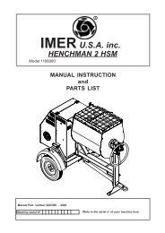
MASONRY <strong>350</strong>F Sawing machine<br />
Model - 1188792<br />
MANUAL INSTRUCTION<br />
and<br />
PARTS LIST<br />
<strong>Manual</strong> Part. number 3210296 - 05/2002<br />
Machine serial N°<br />
Write in the serial n° of your machine here
<strong>IMER</strong> INTERNATIONAL S.p.A.<br />
MASONRY <strong>350</strong> F<br />
Thank-you for purchasing a Masonry <strong>350</strong>F from an Imer U.S.A. dealer. Your decision is an intelligent one.<br />
There is no other sawing machine in the world which delivers the benefits and features of the Masonry <strong>350</strong>F:<br />
- Extremely rigid, mig welded bar steel frame.<br />
.<br />
- 5.5 H.P. Honda engine.<br />
- Compact design for easy trasportation.<br />
- Extremely rigid worktable for a precise cutting.<br />
At <strong>IMER</strong> U.S.A. we continually search for ways to better serve our customers. Should you have an idea or thought to<br />
share with us regarding this product we would appreciate hearing from you. Our motto is "Tools and Services for the<br />
21st Century" . We look forward to delivering the goods.<br />
Thank you again for your purchase.<br />
Mace T. Coleman, Jr.<br />
President, Imer U.S.A, Inc.<br />
<strong>IMER</strong> WEST<br />
207 Lawrence Avenue<br />
So. San Francisco, CA 94080<br />
Tel 650 - 872 - 2200<br />
Fax 650 - 873 - 6482<br />
<strong>IMER</strong> EAST<br />
221 Westhampton Place<br />
Capitol Heights, MD 20743<br />
Tel 301 - 336 - 3700<br />
Fax 301 - 336 - 6681<br />
Fig. 1<br />
7<br />
5<br />
17<br />
3<br />
10<br />
8<br />
12<br />
16<br />
13<br />
2<br />
4<br />
11<br />
14<br />
15<br />
6<br />
1<br />
9<br />
1. Telescopic leg<br />
2. Spray guard<br />
3. Engine<br />
4. Blade support<br />
5. Water pump<br />
6. Guide<br />
7. Emergency switch<br />
8. Worktable<br />
9. Water tank<br />
10. Blade cover<br />
11. Support locking handle<br />
12. Work piece<br />
13. Blade<br />
14. Frame<br />
15. Earth screw<br />
16. Blade guard<br />
17. Accelerator lever<br />
2
Dear Customer,<br />
Congratulations on your choice of purchase: this <strong>IMER</strong> saw, the<br />
result of years of experience, is a fully reliable machine and is<br />
equipped with the latest technical innovations.<br />
- WORKING IN SAFETY<br />
Please read this manual before beginning to assemble or<br />
operate this piece of equipment.<br />
- This OPERATION AND MAINTENANCE manual must be kept on site<br />
by the person in charge, e.g. the SITE FOREMAN, and must always<br />
be available for consultation.<br />
- This manual is to be considered an integral part of the machine, and it<br />
must be preserved for future reference (EN292/2) throughout the<br />
machine’s normal working life. If the manual is damaged or lost, a<br />
replacement may be requested from the saw manufacturer.<br />
- The manual contains important information regarding site<br />
preparation, installation, machine use, maintenance procedures<br />
and requests for spare parts. Nevertheless, the installer and the<br />
operator must both have adequate experience and knowledge<br />
of the machine prior to use.<br />
- To guarantee complete safety of the operator, safe operation<br />
and long life of equipment, follow the instructions in this manual<br />
carefully, and observe all safety standards currently in force for<br />
the prevention of accidents at work. Use personal protection<br />
(safety footwear, suitable clothing, gloves, goggles, etc.).<br />
times.<br />
LEGIBLE.<br />
- Safety glasses or a protective visor must be worn at all<br />
- Ear protection must be worn at all times.<br />
- MAKE SURE THAT WARNING SIGNS ARE ALWAYS<br />
- It is strictly forbidden to carry out any form of<br />
modification to the steel structure or working parts of the<br />
machine.<br />
- <strong>IMER</strong> INTERNATIONAL declines all responsibility for non-compliance<br />
with laws and standards governing the use of this equipment, in<br />
particular; improper use, defective power supply, lack of<br />
maintenance, unauthorised modifications, and partial or total failure<br />
to observe the instructions contained in this manual.<br />
<strong>IMER</strong> INTERNATIONAL is entitled to modify the characteristics of the<br />
sawing machine and/or the contents of this manual without<br />
necessarily updating previous machines and/or manuals.<br />
1. TECHNICAL DATA<br />
Table 1 shows the saw’s technical data, referring to figure 1.<br />
TABLE 1 - TECHNICAL DATA<br />
Blade rpm rpm 2.450<br />
Blade diameter in. 14"<br />
Blade mounting hole in. 1"<br />
Engine type Honda GX 160<br />
Power engine Hp 5.5 / 3.600 rpm<br />
Motor rpm rpm 3.400<br />
Cutting table dimension in. 20" x 17"<br />
Overall dimensions<br />
(widthxlengthxheight)<br />
2. DESIGN STANDARDS<br />
MASONRY <strong>350</strong> F saws are designed and manufactured according<br />
to the following standards: EN 292-1-2; EN 12418.<br />
3. NOISE EMISSION LEVEL<br />
Table 2 indicates the environmental noise levels measured for the panel<br />
saw (lwa) in accordance with EN ISO 3744 and the acoustic pressure<br />
level measured at the operator’s ear with the machine empty (Lpa).<br />
TABLE 2 - [ dB(A)]<br />
SAWING MACHINE TYPE OF MOTOR L PA<br />
L WA<br />
Masonry <strong>350</strong>F ENG HONDA GX 160 K1( Hp 5.5) 95 107<br />
<strong>IMER</strong> INTERNATIONAL S.p.A.<br />
MASONRY <strong>350</strong> F<br />
in. 34" x 47" x 58"<br />
Overall dimensions for<br />
transport<br />
in. 33" x 50" x 46"<br />
(widthxlengthxheight)<br />
Weight lb. 250<br />
Weight for transport lb. 300<br />
Blade rotation direction(seen<br />
from blade clamping flange)<br />
CLOCK WISE<br />
3<br />
4. CUTTING SPECIFICATIONS<br />
This saw model has been specially designed for cutting stone,<br />
ceramics, marble, granite, concrete and similar materials. Only watercooled<br />
diamond blades with continuous or segmented edges (see<br />
paragraph 13) must be used. Under no circumstances must dry<br />
cutting blades be used or materials other than those specified above.<br />
<strong>IMER</strong> INTERNATIONAL declines all responsibility for damage caused<br />
by improper use of the above machine.<br />
5. CUTTING CAPACITY<br />
- max. cutting capacity with vertical blade = 5 " in. one single pass.<br />
- max. height of workpiece: 9" in. in two passes.<br />
- min. width of workpiece: 2" in.<br />
- max. cutting length: 18" in. (with blade lowered), 21" in (with blade<br />
fully raised).<br />
-Blade at 45°: with support at 45° on the work surface.<br />
6. WARNING<br />
- Do not load the saw with workpieces that exceed the specified<br />
weight (max. 90 lb.)<br />
- Ensure stability of machine: it must be installed on a solid base with<br />
a maximum slope of 5° (fig. 2).<br />
- Ensure the workpiece is stable before, during and after cutting: in<br />
any case, workpieces must not overhang the worktable.<br />
- Respect the environment; use suitable receptacles for collection of<br />
cooling water contaminated with cutting dust.<br />
7. SAFETY PRECAUTIONS<br />
- <strong>IMER</strong> saws are designed for work on construction sites and under<br />
conditions of natural light, hence the workplace must be adequately lit.<br />
- The machine must never be used in environments subject<br />
to risks of explosion and/or underground sites<br />
- <strong>IMER</strong> saws may only be used when fitted with all<br />
required safety devices, which must be in perfect<br />
condition.<br />
- The symbol shown on the label (fig. 3) indicates the<br />
warning “ENSURE ALL PROTECTION DEVICES ARE<br />
INSTALLED AND IN PERFECT CONDITION BEFORE<br />
Fig. 3<br />
SWITCHING ON THE MACHINE”.<br />
8. TRANSPORTATION (fig.4)<br />
- WARNING Lock blade support arm by means of the<br />
relative handle before moving the saw (ref. 11, fig. 1). To<br />
transport the machine use slinging equipment with 4 rope<br />
legs, fixing the hooks to the relative attachments (fig. 4).<br />
9. INSTALLATION (fig. 4)<br />
- Lift the machine out of its package using slinging equipment with 4<br />
rope legs. Fix the hooks to the relative attachments.<br />
- Unlock the legs by sliding out the split pins (ref.1).<br />
- Lock the legs at working height. Refit the pins in the leg supports and<br />
insert the split pins.<br />
- Install the machine on a completely even and stable surface.<br />
- Release the carriage from the lever that secures it to the frame.<br />
– Fill the pump with water, unscrewing the connector (fig.10).<br />
When installing on site it is good practice to connect the machine’s<br />
metal structure to the earthing system by means of the screw<br />
(fig.1 ref.15) using an earthing braid (or cable) with a minimum<br />
cross-section of 16 mm 2 .<br />
10. STARTING THE MACHINE.<br />
The endothermic motor is equipped with a centrifugal clutch which<br />
engages automatically, transmitting drive to the cutting wheel as the<br />
engine revs up.<br />
The hazard warnings and the instructions for use and maintenance<br />
contained in the manual enclosed with the endothermic engine must<br />
be read and understood before the engine is started.<br />
1-Check the engine (see enclosed engine manual).<br />
2-Check the oil level in the motor; horizontal motor position (see<br />
enclosed motor manual).<br />
3-Fill the fuel tank (enclosed engine manual).<br />
4-Set the accelerator lever to minimum, so as to start the motor<br />
without turning the cutting wheel (clutch not engaged).<br />
5-Warm the engine by letting it run at low speed<br />
- Emergency-stop: press the engine stop button (ref. 7,<br />
fig. 1), (turn to switch on again).<br />
Keep far enough away from the saw when it is running to avoid<br />
inhaling exhaust gases from the endothermic engine.
- Turn off the engine before topping up the tank with<br />
petrol.<br />
Saws with endothermic engines must be used in the open air. If<br />
they have to be used in closed environments, the openings must<br />
be provided to conduct gases from the engine’s exhaust pipe to<br />
the outside using appropriate non-flammable flexible tubes.<br />
These must be checked for leaks and breakages at the beginning<br />
of every shift.<br />
- Do not start the machine with the blade in the<br />
workpiece.<br />
When the saw is not being used, turn the petrol cock to the OFF<br />
position.<br />
10.1 STARTING ROTATION OF THE CUTTING WHEEL.<br />
Gradually move the lever (ref.17; fig.1) so as to bring the motor<br />
revs up to normal working speed and start the wheel turning at<br />
the cutting speed foreseen.<br />
11. STARTING THE MACHINE<br />
Before cutting:<br />
1 – Check that there is enough cooling water in the tank.<br />
2 - adjust the flow of cooling water by turning the cock next to the<br />
blade guard (do not perform cutting without water).<br />
3 - Ensure that blade rotation corresponds to the indications on<br />
the blade guard.<br />
4 – If everything is in order, work can begin.<br />
12. EMERGENCY - STOP<br />
- In an emergency, stop the machine by pressing the<br />
stop control switch (ref. 7, fig. 1).<br />
13. BLADE INSTALLATION (Fig.5)<br />
By means of a hex wrench no.10, unscrew the 3 screws that<br />
lock the moving blade guard (ref.3). Use a hex wrench no. 13 to<br />
remove the screw that locks the flanges on the disc: this screw<br />
has a left-hand thread (rif.1). Remove the mobile flange (rif.2)<br />
and check that the flanges, disc shaft and blade are not damaged.<br />
- Never use worn blades or blades with missing segments.<br />
- Only use blades that are designed for the number of<br />
revolutions indicated on the machine rating plate.<br />
- Check that blade rotation corresponds to that<br />
indicated on the blade guard.<br />
Centre the blade against the fixed flange, position the mobile<br />
flange and tighten the securing screw by means of a hex<br />
wrench no. 13 (turn clockwise). Refit the moving blade guard,<br />
tightening the 3 screws (ref.3).<br />
- Ensure that the blade guard (ref.3) is locked<br />
securely into position.<br />
- WARNING! An incorrectly installed blade, or a<br />
screw insufficiently tightened can provoke damage to<br />
the machine or injury to persons.<br />
- Note that the blade must have<br />
an external diameter of 14"in. , a<br />
central hole diameter of 1" in. and max.<br />
thickness of 1/8" in..<br />
- Check that the blade to be used<br />
is suitable for the material to be cut.<br />
(fig. 6).<br />
- Do not use blades for wood!<br />
<strong>IMER</strong> INTERNATIONAL S.p.A.<br />
MASONRY <strong>350</strong> F<br />
Fig. 6<br />
14. USE<br />
- Leave a space of at least 5 ft. around the machine to operate<br />
in full safety.<br />
- Do not allow other persons to approach the<br />
machine during cutting.<br />
- Never use the machine in fire-risk areas. Sparks can cause<br />
fire or explosions.<br />
- Make sure that the machine is switched off before positioning<br />
or handling.<br />
- Always ensure that the blade is free of any contact before start-up.<br />
- Ensure correct installation of all protective devices.<br />
- Before starting work, fill the water tank. Top up during operation<br />
whenever necessary: N.B. the pump suction hose must always remain<br />
immersed in water.<br />
- WARNING! For safety purposes the removal of protective<br />
guards from the machine is strictly prohibited.<br />
- WARNING! Always switch off the machine before<br />
carrying out blade adjustment.<br />
Loading and unloading pieces on the machine cutting table.<br />
To avoid the risk of accidental contact with the cutting wheel, the<br />
pieces must be positioned and removed from the carriage with the<br />
cutting wheel stopped. This is done by adjusting the lever (ref.17;fig.1)<br />
so as to reduce the revs to minimum, thus disengaging the clutch.<br />
14.1 VERTICAL BLADE MOVEMENT<br />
To raise or lower the blade, slacken the support locking handle turning<br />
it anti-clockwise (ref. 11, fig. 1). The blade support remains free to<br />
rotate, so it can be secured in the desired position, fully tightening the<br />
handle (ref. 11, fig. 1).<br />
- Ensure that the locking handle is tightened fully before<br />
starting work.<br />
14.2 BLADE POSITIONING FOR 45° CUTS<br />
To make a cut at 45° the 45° support on the carriage is necessary.<br />
Once the workpiece is correctly positioned, cutting can begin, starting<br />
the endothermic engine.<br />
14.3 CUTTING<br />
For safe use of the machine when cutting, push the carriage forwards<br />
as the cut advances, placing your hands to the two sides of the<br />
carriage. Never push directly on the piece to be cut.<br />
- Check that the blade is aligned with the cutting line.<br />
- Place the workpiece on the worktable (ref. 8, fig. 1), resting firmly<br />
against the stop.<br />
- Start the engine.<br />
- Wait until the water reaches the blade.<br />
- Begin cutting.<br />
- Horizontal cutting movement is carried out by pulling the carriage<br />
towards the blade.<br />
- As cutting thickness increases, the blade is subjected to<br />
greater stress. To avoid overloading the engine, the operator<br />
should continually check blade feed speed. The speed will<br />
also depend on the characteristics of the material being cut<br />
(hardness, toughness etc.).<br />
14.3.1 CUTS WITH BLADE LOWERED FROM ABOVE<br />
Bring the blade support to its highest position and lock. Position the<br />
workpiece on the worktable. Start the machine and begin vertical<br />
cutting until the blade reaches its lowest point. Lock the support locking<br />
handle and proceed with horizontal cutting<br />
14.3.2 BLADE CHANGE<br />
To change the blade refer to section 13.<br />
15. MAINTENANCE<br />
- WARNING. Servicing must always be carried out by<br />
skilled personnel and only after the endothermic engine has<br />
been turned off.<br />
-Always keep the guards in proper working order and<br />
free from damage.Take particular care to ensure that the<br />
blade guards are kept efficient and clean, replacing them if<br />
they are damaged.<br />
- WARNING. Recommended product for cleaning<br />
mechanical parts: WD-40.<br />
Do not leave the machine outside: it must always be protected from<br />
the weather.<br />
Below is a list of the cleaning operations that must be carried out at the<br />
end of every shift.<br />
15.1 TANK CLEANING<br />
Empty the tank by removing the drain plug. Remove cutting residue<br />
using a jet of water.<br />
4
15.2 TANK REMOVAL (Ref.Fig.7).<br />
- Lift the tank (ref.1) to detach it from its supports (ref.2) and<br />
remove it from the side indicated by the arrow.<br />
15.3 WORK SURFACE CLEANING<br />
Always keep work surfaces clean. Residual dirt can impair<br />
cutting precision.<br />
15.4 GUIDE RAIL CLEANING<br />
It is good practice to remove all traces of dirt from the guides.<br />
15.5 CLEANING AND MAINTENANCE OF COOLING<br />
CIRCUIT<br />
- If water does not reach the blade stop the machine immediately<br />
to avoid blade damage.<br />
- After switching off the machine ensure that the water level is<br />
sufficient.<br />
-Check that there is water in the pump by unscrewing the<br />
connector, and if necessary top up until water flows out (fig.10).<br />
- WARNING. Before starting the panel saw for the<br />
first time, or when starting it after long periods of<br />
inactivity, fill the pump with water as described above.<br />
- At the end of every shift, unscrew the suction hose filter and<br />
clean it. Then, circulate some water through it placing inside a<br />
bucket of clean water.<br />
15.6 TENSIONING THE DRIVE BELT (fig. 8)<br />
- Turn off the endothermic engine.<br />
- Unscrew the 4 screws that lock the movable belt guard (ref. 1).<br />
- Loosen the two screws (ref. 2) that clamp the water pump to<br />
the bracket and move the pulley away so that it does not touch it.<br />
- Loosen the 4 screws (ref. 3) that clamp the endothermic<br />
engine to the blade support.<br />
- Tension the belt using the nut (ref. 4): apply a force of about<br />
F=14 lb. to the centre of the free section of the belt, the arrow<br />
should be about f=1/4" in. (fig. 9).<br />
- Tighten the screws on the endothermic engine, checking the<br />
alignment of the engine pulley and the blade pulley<br />
- Lower the water pump until the pulley touches the drive belt.<br />
Tighten the two screws.<br />
- Refit the guard and lock it using the 4 screws.<br />
- To avoid shortening the life of the belt, the bearings<br />
and the blade shaft, do not overtension the belt. Finally,<br />
check the two pulleys are aligned.<br />
15.7 DRIVE BELT REPLACEMENT<br />
Repeat the operations described in section 15.6, replacing the<br />
belt before tensioning it.<br />
15.8 ENDOTHERMIC ENGINE MAINTENANCE<br />
Read the Honda manual carefully... and follow their instructions.<br />
Changing the oil (with the engine in horizontal position) and<br />
cleaning the air filter frequently ensure a reliable and long lasting<br />
engine.<br />
When you may need Honda Engine Service or Warranty<br />
Assistance take the machine to your local Honda power<br />
equipment dealer, they will honour the Warranty throughout<br />
America.<br />
- It is always a good idea to check the oil level in the<br />
engine cranckcase at the start of each working day.<br />
Clean oil at the correct level markes for an engine that<br />
will last and last.<br />
15.9 REPAIRS<br />
- Do not start the saw during repair work.<br />
Only use genuine <strong>IMER</strong> spare parts and do not modify<br />
them.<br />
- If the guards are removed to carry out repairs,<br />
they must be refitted properly when the repair work is<br />
finished.<br />
<strong>IMER</strong> INTERNATIONAL S.p.A.<br />
MASONRY <strong>350</strong> F<br />
16. TROUBLESHOOTING<br />
- WARNING. Stop the saw and turn off the<br />
endothermic engine before carrying out any<br />
maintenance.<br />
FAULT CAUSE REMEDY<br />
Vertical blade - locking knob too tight - Slacken knob<br />
movement not<br />
smooth<br />
Horizontal carriage<br />
movement not<br />
smooth<br />
- Guide rails dirty - Clean the guide rails<br />
Lack of cooling water<br />
supply to blade<br />
Blade does not cut<br />
Refer to section 15.5: "cleaning and<br />
maintenance of cooling circuit" (Chapter 15.5)<br />
- Blade is worn<br />
- Drive belt not<br />
tensioned<br />
Motor starts but Belt is broken<br />
blade does not rotate<br />
- Fit new blade<br />
-Tension the belt<br />
Replace drive belt<br />
5
<strong>IMER</strong> INTERNATIONAL S.p.A.<br />
MASONRY <strong>350</strong> F<br />
Fig. 2 Fig. 4<br />
1<br />
1<br />
5° MAX<br />
Fig. 5<br />
Fig. 7<br />
3<br />
1<br />
1<br />
2<br />
2<br />
1<br />
Fig. 8<br />
Fig. 9<br />
2<br />
1<br />
3<br />
Fig. 10<br />
4<br />
1<br />
UNSCREW<br />
6
<strong>IMER</strong> INTERNATIONAL S.p.A.<br />
MASONRY <strong>350</strong> F<br />
TAV. 1<br />
TAV.1 - ASSEMBLY OF MOTOR<br />
RIF. COD. GB NOTE<br />
1 3210291 MOTOR HONDA GX 160<br />
2 3210139<br />
3 3210148<br />
4 3210185 BELT<br />
5 3210159 PULLEY<br />
BELTS INTERNAL<br />
COVER<br />
BELTS EXTERNAL<br />
COVER<br />
6 2224190 WASHER 8X32 Z<br />
7 2222076 BOLT M8X25 Z<br />
8 2222176 BOLT M8X50 Z<br />
9 2222004 BOLT M8X35 Z<br />
10 2224140 WASHER 8X18 Z<br />
11 2223923<br />
SELF LOCKING<br />
NUT<br />
M8 Z<br />
12 3203921 BOLT M5X10 Z<br />
13 2222021 BOLT M6X16 Z<br />
TAV. 2<br />
TAV.2 - WHEEL KIT<br />
Rif. Cod. GB Note<br />
1 2226700 SPLIT PIN<br />
2 2211150 WHEEL<br />
3 3206261 LEFT TUBE GUIDE<br />
4 3206262 RIGHT TUBE GUIDE<br />
5 2222082 SCREW 5739 M 10X60 Z<br />
6 2223650 DISK 5588 M10 Z<br />
7 3206641 WASHER 6592 28X50X2 Z<br />
8 3206260 WHEEL TUBE<br />
TAV. 3<br />
TAV.2 - 45° SUPPORT<br />
Rif. Cod. GB Note<br />
1 2284859 KNOB<br />
7
<strong>IMER</strong> INTERNATIONAL S.p.A.<br />
MASONRY <strong>350</strong> F<br />
TAV. 4<br />
TAV. 4 - MAC H IN E S TR U C TU R E<br />
R IF. C OD . GB N OTE<br />
1 3208421 C A RRIAGE<br />
2 2222061 B OLT 5739 M 8X 20 Z<br />
3 2222515 B OLT 5931 M 8X 16 Z<br />
4 3204945 B EA RING 608-2RS 1<br />
5 2223923 S ELF LOC K ING NUT M 8 Z<br />
6 3207397 W HE EL<br />
7 2222090 B OLT 5737 M 8x75 Z<br />
8 3210193 GUID E B AR<br />
9 3208442<br />
10 3208441<br />
LE FT FE NC E<br />
A D HE SIV E LA BE L<br />
RIGHT FE NC E<br />
A D HE SIV E LA BE L<br />
11 3205581 RUB BE R C OAITING<br />
12 2224612 WA SHE R D .21X43 Z<br />
13 3206086 P IN<br />
14 3201517 LE G<br />
15 3210178<br />
C UTTING HEA D<br />
GROUP<br />
16 3206096 S UP PORT<br />
17 2223920 S ELF LOC K ING NUT M 10 Z<br />
18 3201015 P LUG<br />
19 2222587 S C RE W 5933 M 8X 20 Z<br />
20 3210171 S PRAY GUARD<br />
21 3210169 FRA ME<br />
22 3205526<br />
WATER RUN-OFF<br />
TRAY<br />
23 2222425 S C RE W AUTOFOR.TE 4,2X 13<br />
24 3204818 D RUM<br />
25 2235428 P LUG<br />
26 3210173 WATER PUMP<br />
27 3210183 WA TER FILTER<br />
28 2224320 WA SHE R D .10X21X 2<br />
29 3210158 S HA FT<br />
30 2209450 NYLON B US HING<br />
31 2222002 S C RE W 5739 M 6x16 Z<br />
32 2222059 S C RE W 5739 M8X 25 Z SX .<br />
33 3208414 LE VE R<br />
34 3208422 GONIOMETE R<br />
35 3207213<br />
GUID E B AR<br />
S UP PORT<br />
36 3208428 TROLLEY S LID E<br />
37 3210236<br />
GUID E B AR<br />
S UP PORT SX<br />
38 2222580 S C RE W M 4X20 Z<br />
TAV. 4 - M ACHINE ST RUCT URE<br />
RIF. COD. GB NO TE<br />
39 3210153<br />
RO TATIO N<br />
ADJUSTING RO D<br />
40 3209333 KNO B M 8 Z<br />
41 3210297 TRO LLEY CLAM PING<br />
42 2222016 SCREW 5739 M 6x20 Z<br />
43 2223924 NUT M 6 Z<br />
44 3209332 CAM<br />
45 2222018 SCREW 5931 M 8X35 Z<br />
46 2224534 WASHER 6X12.5 Z<br />
47 3210416<br />
48 3210175<br />
HO OSE JO INT 90°<br />
1/4"<br />
EM ERGENCY<br />
SW ITCH<br />
49 2288885 HANDGRIP<br />
50 3206513 BEARING 6205 2RS<br />
51 3210179 DISC CO VER<br />
52 3232759 O IL SEAL RING 35X52X7<br />
53 3204777 INNER FLANG E<br />
54 3204776 O UTER FLANG E<br />
55 3210156 WATER HOSE<br />
56 3210629 BEARING 6006 2RS<br />
57 3205635 VALVE<br />
58 3210140 BLADE COVER<br />
59 2222006 SCREW M 8X30 Z<br />
60 3210189 SELF LO CKING NUT M 20 Z<br />
61 3210418 HO OSE JO INT 1/4"<br />
62 3204889 LEVER<br />
63 3210160 PULLEY<br />
64 2224910 WASHER DEV. D.10 Z<br />
65 3210142<br />
66 3210152 SPRING<br />
BLADE G UARD<br />
RO TATIO N ROD<br />
67 2227320 STO P RING E/20<br />
68 3210181 SPRING PIN<br />
69 3210206 SPRAY G UARD<br />
70 3210149 TIE RO D SCREW<br />
71 3210229 PUM P CO VER SHEET<br />
72 2226778 HO OSE JO INT F3/8<br />
73 3210542 DISK PROTECTIO N DX<br />
74 3210543 DISK PROTECTIO N SX<br />
75 3210576 NYLON WASHER 8.4XX17X1.5<br />
76 2224140 WASHER 8X18 Z.<br />
77 2222110 SCREW 8X80 Z<br />
8
ONE YEAR WARRANTY<br />
We warrant to the original purchaser that the <strong>IMER</strong> equipment described herein<br />
(the "equipment") shall be free from defects in material and workmanship under<br />
normal use and service for which it was intended for a period of one (1) year from<br />
the date of purchase by the original purchaser.<br />
Our obbligation under this warranty is expressely limited to replacing or repairing,<br />
free of charge, F.O.B. our designated service facility, such part or parts of the<br />
equipment as our inspection shall disclose to be defective. Parts such as engines,<br />
motors, pumps, valves, electric motors, etc. furnished by us but not manifactured by<br />
us will carry only the warranty of the manifacturer. Transportation charges or duties<br />
shall be borne by the purchaser. This shall be the limit of our liability with respect to<br />
the quality of the equipment.<br />
This warranty shall not apply to any equipment, or parts thereof, which has been<br />
damaged by reason of accident, negligence, unreasonable use, faulty repairs, or<br />
which has not been mantained and operated in accordance with our printed<br />
instructions for our equipment. Further, this warranty is void if the equipment, or any<br />
of its components, is altered or modified in any way.<br />
THIS WARRANTY IS EXPRESSLY IN LIEU OF ALL OTHER WARRANTIES,<br />
EXPRESSED OR IMPLIED, INCLUDING ANY IMPLIED WARRANTY OF<br />
MERCHANTABILITY OF FITNESS FOR A PARTICULAR PURPOSE.<br />
We make no other warranty, representation or guarantee, nor is anyone authorized<br />
to make one on our behalf. We shall not be liable for any consequential damage of<br />
any kind, including loss or damage resulting, directly or indirectly, from the use or<br />
loss of use of the machine. Without limiting the generality of the foregoing, this<br />
exclusion from liability embraces the purchase's expenses for downtime, damages<br />
for which the purchaser may be liable to other persons, damages to property, and<br />
injury or death of any persons.<br />
This warranty shall not be deemed to cover maintenance parts, including but not<br />
limited to blades, belts, hoses, hydraulic oil or filters, for which we shall have no<br />
responsability or liability whatsoever.<br />
<strong>IMER</strong> U.S.A., Inc.<br />
207 Lawrence Avenue<br />
South San Fancisco, California 94080<br />
(650) 872-2200
This is a contact addendum to our manuals<br />
Imer <strong>USA</strong> East<br />
221 Westhampton Pl<br />
Capitol Heights, MD 20743<br />
Phone: 301-336-3700<br />
Fax: 301-336-6687<br />
Order Fax:301-336-5811<br />
Imer <strong>USA</strong> West<br />
3654 Enterprise Ave<br />
Hayward, CA 94545<br />
www.imerusa.com<br />
800-275-5463