20% - IMER USA.
20% - IMER USA.
20% - IMER USA.

Create successful ePaper yourself
Turn your PDF publications into a flip-book with our unique Google optimized e-Paper software.
(1188076 115V 60Hz)<br />
<br />
<br />
53036 POGGIBONSI (SIENA) Loc. SALCETO<br />
<br />
tel.: 0577 983300 - fax: 0577 983304
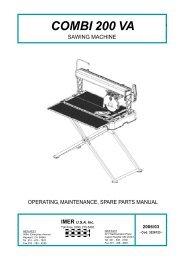
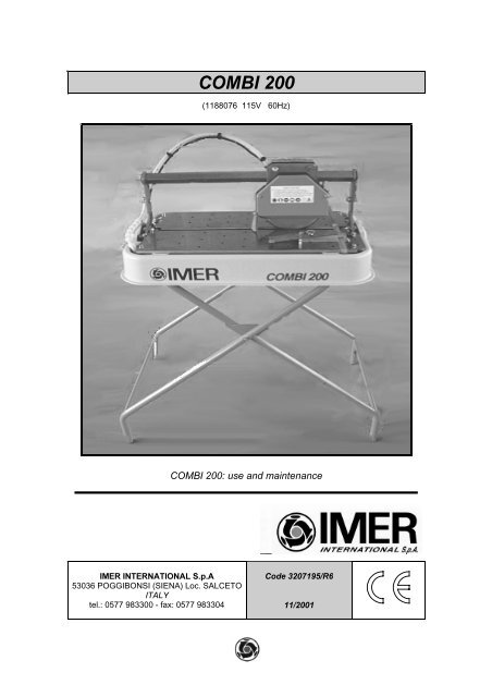
COMBI 200: use and maintenance<br />
<br />
___________________________________________________________________________________________________________________<br />
<br />
<br />
<br />
Dear Customer, congratulations on your purchase: the tile/stone<br />
cutter is ideal for cutting tiles, thresholds and every kind of slab or fired tile.<br />
This manual must be kept by the <br />
within the building site, so it is always available for consultation. The manual is<br />
to be considered part of the machine and must be kept for future reference<br />
(EN292/2) for the whole machine life. If it is damaged or mislaid, a new copy<br />
can be requested from the manufacturer. To guarantee the safety of the<br />
operator, the safety of machine functioning and a long life for the machine, the<br />
instructions in the manual must be respected, together with the safety and<br />
work accident prevention regulations as per current legislation. Suitably safe<br />
equipment must be used (safety shoes, gloves as per <br />
).<br />
When writing to or telephoning your Agent or <br />
for any reason involving the machine, always supply the following details:<br />
1. machine model<br />
2. serial number<br />
3. voltage and frequency<br />
4. period of use - number of working hours<br />
5. type of disk used<br />
<br />
Fig.1.1<br />
<br />
When compiling this manual, we kept in due consideration all the adjustment<br />
and service operations which are part of normal maintenance.<br />
We recommend that no repairs or operations are carried out which are not<br />
indicated in this manual.<br />
All operations which require parts to be dismantled must only be carried out by<br />
qualified personnel.<br />
<br />
Before beginning machining with the tile/stone cutter, read this instructions<br />
manual carefully to understand the machine, its uses and any possible<br />
counter-indications.<br />
The machine must be used exclusively for the uses hereby specified, use it as<br />
recommended in this manual and do not try to tamper with it or force it, or to<br />
use it for purposes not mentioned.<br />
declines all responsibility in the case of non<br />
observance of the laws which regulate the use of such equipment, in<br />
particular: improper use, power supply anomalies, neglect of maintenance,<br />
unauthorized modifications, partial or total non observance of the instructions<br />
contained in this manual.<br />
<br />
<br />
<br />
The machine is marked by the captions punched on the metal plate on the<br />
upper part of the machine (Fig.1.1-A).<br />
Fig.1.2<br />
<br />
(Fig.1.2) is a small tile/stone cutter designed and manufactured by<br />
<strong>IMER</strong> INTERNATIONALSpafor cutting tiles, ceramics and stone in general.<br />
The fundamental qualities of the machine are accuracy, reliability and<br />
lightness which combine to make it a unique machine.<br />
<br />
The machine can cut the following materials: ceramic tiles and stone in<br />
general with the dimensions specified in section 1.6.1.<br />
<br />
The machine can only cut the materials mentioned in section 1.5.1. Using the<br />
machine with other materials is forbidden.<br />
♦<br />
In any case, before carrying out machining different from those<br />
envisaged by the manufacturer or machining of materials different<br />
from those for which the machine was manufactured, we<br />
recommend that you contact <br />
<br />
<br />
<br />
<br />
<br />
<br />
<br />
<br />
Type<br />
Machine model<br />
No.<br />
Serial number<br />
Year<br />
Year of manufacture<br />
Volt<br />
Electrical voltage in Volts<br />
Hz<br />
Electrical frequency in Hz<br />
Kg<br />
Weight<br />
Amp.<br />
Electrical absorption in Amps<br />
rpm<br />
Number of revs. per minute of the disk<br />
kW<br />
Nominal power<br />
External diameter of disk<br />
Disk hole diameter<br />
<br />
mm 200<br />
mm 15.875<br />
mm 650x420x20<br />
mm 775x520x360<br />
mm 805x530x370<br />
Kg 24<br />
Kg 27<br />
<br />
<br />
mm 430<br />
430<br />
<br />
<br />
mm 40<br />
20<br />
11<br />
23<br />
1
COMBI 200: use and maintenance<br />
<br />
___________________________________________________________________________________________________________________<br />
<br />
<br />
<br />
V 115<br />
Hz 60<br />
kW 0.37<br />
<br />
rpm 3430<br />
rpm 3430<br />
A 5.6<br />
<br />
was designed and manufactured by applying the following<br />
standards: <br />
<br />
The following is a description of the various types of symbol which will be seen<br />
when reading this manual.<br />
<br />
♦<br />
The notes highlight information which is particularly useful for correct machine<br />
functioning.<br />
<br />
∆<br />
Failure to observe the safety warnings may lead to injury, both for the operator<br />
and other persons.<br />
was designed in line with safety standards established at a<br />
European level.<br />
The safety devices, as per machine directive were designed with<br />
utmost importance given to the safety of the operator.<br />
Safety and accessibility are combined perfectly in ; the operator is<br />
fully protected, without any risks.<br />
<br />
The machine is fitted with fixed guards secured with fixing screws and guards<br />
which prevent access to the moving and dangerous parts. All the fixed guards,<br />
covers and screens secured with screws have been designed to protect the<br />
operators (maintenance personnel, technicians, etc.) from injuries caused by<br />
electrical discharges and moving mechanical parts.<br />
Therefore, there is no envisaged use of the machine where the guards have<br />
been modified or removed from the positions which they have been designed<br />
for.<br />
∆<br />
<br />
<br />
<br />
<br />
<br />
<br />
<br />
The danger signal indicates situations of special danger where the operator<br />
risks serious injuries.<br />
<br />
When the text refers to an illustration, for example: " ... (Fig.) ...", refer<br />
to part in figure number Some illustrations are included in the context,<br />
while others are annexed.<br />
The confirms that the machine has<br />
been designed according to and complies with European Community<br />
requirements and regulated by precise Legal Standards. (DIR. 89/392/EEC -<br />
91/368/EEC)<br />
<br />
Remember that this machine has been manufactured to offer, as well as better<br />
performance, maximum safety: however, it is the operator who must<br />
guarantee this safety, by taking the necessary precautions in all work phases.<br />
The operator is advised to:<br />
<br />
Given its small size and lightness (only 24 Kg), Combi 200 can be lifted and<br />
unloaded manually by the operator using the handles on the container tank.<br />
<br />
<br />
<br />
Put the machine in the most suitable position, bearing in mind the electrical<br />
connections. The space required for use and maintenance is shown in the<br />
diagram below (Fig.2.2).<br />
♦<br />
When moving the machine on the site, always take care to secure<br />
the head with the lever (Fig. 3.1-G) and lift the machine with the<br />
handles on the tank (Fig. 2.2/A-A).<br />
<br />
<br />
<br />
<br />
<br />
<br />
<br />
<br />
<br />
<br />
<br />
<br />
<br />
<br />
<br />
<br />
<br />
<br />
<br />
<br />
<br />
<br />
<br />
<br />
<br />
<br />
<br />
<br />
<br />
<br />
<br />
<br />
<br />
<br />
<br />
<br />
<br />
<br />
<br />
<br />
<br />
<br />
<br />
<br />
<br />
<br />
<br />
<br />
<br />
<br />
Fig.2.2<br />
The machine may be supplied on an optional support stand (code 118.76.00)<br />
as shown below (Fig.3.1/I).<br />
♦<br />
<br />
<br />
Fig.2.2/A<br />
Make sure that the stand is positioned on the supports on the<br />
bottom of the tank.<br />
<br />
Check that the mains power supply unit to which the machine is connected<br />
has an earth connection as envisaged by current standards, and that the<br />
socket is operating correctly.<br />
<br />
2
COMBI 200: use and maintenance<br />
<br />
___________________________________________________________________________________________________________________<br />
can be used for 90 degree vertical cutting and 45 degree tilted<br />
♦ Remember that there must be an overload protection upstream of cutting.<br />
the mains power supply unit which can guarantee the safety of all For vertical cutting, the pieces must have a maximum length of 430 mm and a<br />
the conductors from short circuiting and overload.<br />
maximum thickness of 40 mm. For 45 degree tilted cutting, the pieces must<br />
have a maximum length of 430 mm and a maximum thickness of 20 mm.<br />
<br />
<br />
<br />
115V-60Hz code 1187627<br />
Note the power installed (see machine identification plate) to dimension the<br />
section of cable for the electric wiring, considering a maximum current<br />
capacity of 4 for lengths no higher than 2 for<br />
lengths between <br />
∆<br />
∆<br />
∆<br />
∆<br />
∆<br />
<br />
<br />
<br />
<br />
<br />
<br />
<br />
<br />
<br />
<br />
<br />
<br />
<br />
<br />
<br />
<br />
<br />
<br />
<br />
<br />
<br />
<br />
<br />
<br />
<br />
<br />
Fig.3.1<br />
The machine consists of a mobile cutting part (Fig.3.1-A), a fixed machine<br />
support frame (Fig.3.1-B), a disk cooling tank (Fig.3.1-C) and an adjustment<br />
unit (Fig.3.1-E).<br />
The machine is fitted with protection devices to guarantee maximum<br />
functioning safety (Fig.3.1-D).<br />
<br />
functions as follows:<br />
1. The piece to be machined is placed against the fence (Fig. 3.3 -E)<br />
of the work surface with the required angle using the protractor<br />
(Fig.3.1-E);<br />
2. Select the cutting angle, vertical (Fig.3.1) or tilted at 45° (Fig.3.3);<br />
to move the operating head to the fence, simply release the<br />
securing knob (Fig.3.1-F) (Fig.3.2-A) for the operating head angle<br />
setting, then secure the clamping knob again;<br />
<br />
<br />
<br />
<br />
<br />
<br />
The motor is driven by pressing the push-button on the handle (Fig.3.3/A).<br />
<br />
Electric motor characteristics<br />
115V-60Hz<br />
Power (Kw) 0.37<br />
Nominal voltage (V) 115<br />
Frequency (Hz) 60<br />
Number of poles 2<br />
R.p.m. 3430<br />
Isolation class<br />
S6<br />
Protection grade<br />
IP55<br />
Type of mechanical casing<br />
63 B14<br />
Capacitor (µF)<br />
35(D.36x90)<br />
<br />
<br />
<br />
Protection from machine noise ( symbol) in the workplace has been<br />
designed to meet the requirements of <br />
.<br />
<br />
<br />
<br />
<br />
<br />
<br />
<br />
Fig.3.2<br />
3. Turn the clamping knob for the operating head angle setting<br />
(Fig.3.1-G);<br />
4. Start up the machine using the maintained push-button near the<br />
handle (Fig.3.3-A).<br />
♦<br />
Make sure the tank is full of water during operations.<br />
5. Press the piece against the table by hand<br />
♦<br />
Apply a suitable pressure for the piece to be cut so that the motor<br />
is not overloaded (motor under normal operating conditions<br />
6. Move the operating unit and begin the cut; if the motor stops due to<br />
overloading, retract the disk from the workpiece and allow the<br />
motor to reach working speed before re-starting the cut.<br />
The cut must be made near the fences on the work table.<br />
♦<br />
If the 45° and 90° cuts are incorrect, adjust the screws on the two<br />
arms (Fig. 3.3.-F).<br />
A<br />
B<br />
<br />
<br />
<br />
Once the machine installation has been completed, machining can begin.<br />
consists of a stainless steel cutting surface. The 0.37 kW motor<br />
and the cutting head (work unit) are fitted on a steel bar tilted at 45° to ensure<br />
high cutting precision. The tile/stone cutter is placed on a tank, in plastic<br />
shock-proof material, which contains water. The tank can be easily removed<br />
for cleaning. There is a cooling pump immersed in the tank under the work<br />
table which supplies the water jet for cooling the cutting disk.<br />
3
COMBI 200: use and maintenance<br />
<br />
___________________________________________________________________________________________________________________<br />
<br />
<br />
<br />
<br />
<br />
<br />
<br />
Clean the tank every time that sediment forms on the bottom, or at least once<br />
a day. Failure to clean the tank could create problems for the immersion pump<br />
which circulates water for cooling the cutting disk. To clean the tank, remove it<br />
from the machine, secure the head, take it by the arms and wash it down with<br />
direct water jets (this operation prevents direct contact of the electric parts and<br />
the water jets), then clean it by hand with cloths or brushes.<br />
♦<br />
♦<br />
Pay attention to the cable when replacing the machine on the tank.<br />
Pay attention to the pump when releasing the machine and placing<br />
it on the table.<br />
Fig.3.3<br />
<br />
The operating unit consists of the following:<br />
1. A sliding unit guided by wheels on bearings (Fig.3.3-B and Fig.3.1-<br />
A);<br />
2. An electric motor (Fig.3.3-C);<br />
3. A cutting unit consisting of a cutting disk (Fig.3.1-D);<br />
4. A maintained push-button (Fig.3.3-A);<br />
5. A cutting disk guard (Fig.3.1-H);<br />
6. A handle (Fig.3.3-D);<br />
7. An operating head clamping knob (Fig.3.1-F);<br />
8. A safety knob (Fig.3.1-G);<br />
<br />
<br />
<br />
The normal operations for ordinary maintenance can be carried out by non<br />
specialized personnel provided they observe the safety indications listed in the<br />
previous and following paragraphs.<br />
<br />
The machine must be cleaned when the machine is at a standstill.<br />
♦<br />
♦<br />
♦<br />
♦<br />
<br />
<br />
Do not used compressed air: this would send dust and residuals<br />
into the most inaccessible corners of the machine.<br />
Check that the cooling liquid nozzles are not blocked.<br />
We recommend that the cooling water in the tank is changed every<br />
day.<br />
Do not use detergents or lubricants which may harm the materials<br />
of which the machine is made.<br />
<br />
<br />
<br />
<br />
To dispose of the waste materials produced by the machine, current<br />
legislation must be observed.<br />
<br />
Repairs of the electrical systems must only be carried out by specialized<br />
personnel. The spare parts to be used for mechanical repairs must be original<br />
parts and they should not be modified in any<br />
way.<br />
No further maintenance is required for the special structure of .<br />
Check that the plug and plug-switch unit contacts are not damaged. If they are<br />
oxidized, clean them immediately.<br />
<br />
If you have to dismantle the electric motor, take care when re-fitting it on the<br />
fixing plate.<br />
∆<br />
<br />
<br />
<br />
<br />
The diamond-dressed disk is manufactured in special material for cutting the<br />
materials described above and must be cooled with water during the work<br />
phase.<br />
To replace the disk, the following procedure must be followed:<br />
1. Secure the axial slide of the operating head with the lever.<br />
2. Dismantle the front guard.<br />
3. Loosen the securing nut by turning it in a clockwise direction (left<br />
hand thread), using a 10 mm spanner.<br />
4. Remove the disk by first moving it and then tilting it slightly to<br />
extract it from its housing.<br />
♦<br />
When removing the disk, ensure that the cooling water jet nozzle is<br />
not bent.<br />
5. Insert the new disk, by carrying out the operations described in<br />
point 4 in reverse order, paying particular attention to the rotation<br />
direction of the disk.<br />
6. Secure the disk nut correctly by turning it in an anti-clockwise<br />
direction (left hand thread), ensuring that there is a torque of 1.8<br />
Kgf.m<br />
<br />
<br />
<br />
<br />
<br />
<br />
After a work period of approximately one year, check that the operating unit is<br />
stable; if not, carry out the following operations to stabilize it:<br />
1. Release the two nuts (Fig.4.1-A);<br />
2. Press down on the operating unit (near the plate)<br />
3. First push the right wheel in a diagonal direction towards the inside<br />
<br />
<br />
<br />
Fig.4.1<br />
4. Secure the wheel nut by pressing it.<br />
5. Do the same with the left wheel.<br />
4
COMBI 200: use and maintenance<br />
<br />
___________________________________________________________________________________________________________________<br />
<br />
<br />
The appendix contains the diagrams for the various units present in the<br />
machine and the reference drawings. This section also contains the<br />
documentation for the components installed in the machine and referred to in<br />
the manual.<br />
<br />
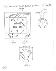
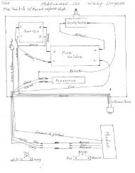
For wiring, the operator must consult the diagrams below<br />
S1<br />
C1<br />
X1<br />
PE<br />
N<br />
L1<br />
M1<br />
M2<br />
Control switch<br />
Capacitor<br />
Disk motor connector<br />
Overload line conductor<br />
Neutral line conductor<br />
Phase line conductor<br />
Disk motor<br />
Pump motor<br />
<br />
Fig.5.1<br />
<br />
<br />
<br />
<br />
<br />
When the start switch is pressed, the motor − No mains voltage.<br />
does not start<br />
− The plug and socket are not connected − Check the mains.<br />
properly.<br />
− The power supply cable is disconnected − Reset the correct connection.<br />
from the cabinet.<br />
− An electric wire inside the motor terminal − Replace the cable.<br />
board is disconnected.<br />
− Contact an electrician for assistance.<br />
− An electric wire inside the cabinet is − Contact an electrician for assistance.<br />
disconnected.<br />
− The mains switch is faulty.<br />
− Change the switch.<br />
No cooling water for the disk. − Consult machine cleaning, section 4.2 ,and tank cleaning, section 4.5<br />
The disk does not cut. − Incorrect disk rotation direction.<br />
− Dismantle the disk and reposition it in the<br />
direction indicated on the disk label.<br />
− Worn disk.<br />
− Fit a new disk.<br />
5
COMBI 200: use and maintenance<br />
6<br />
___________________________________________________________________________________________________________________<br />
<br />
<br />
<br />
<br />
When ordering spare parts, indicate the following:<br />
1. Machine type.<br />
2. Code and reference number alongside each definition.<br />
3. Serial number and year of manufacture, shown on the machine plate.<br />
Fig.7.1/A<br />
6
COMBI 200: use and maintenance<br />
7<br />
___________________________________________________________________________________________________________________<br />
<br />
<br />
1 2223570 NUT<br />
2 2224140 WASHER<br />
3 3206312 CLAMP<br />
4 2223920 NUT<br />
5 3206385 CABINET GUARD<br />
6 3207397 WHEEL<br />
7 3207394 SPACER<br />
8 3206744 MOTOR SUPPORT PLATE<br />
9 2222516 SCREW<br />
10 3207118 ARM CLAMP<br />
11 3207393 SPACER<br />
12 1193849 DISK<br />
13 3206409 GUARD<br />
14 2222021 SCREW<br />
15 1222013 SCREW<br />
16 3208759 SCREW<br />
17 3207015 FLANGE<br />
18 3207014 FLANGE<br />
19 3205941 COOLING TUBE<br />
20 3205985 SPLASH GUARD<br />
21 2224340 WASHER<br />
22 2223655 M 10 LOW NUT<br />
23 2225749 SELF-LOCKING CLAMP<br />
24 3206231 SPLASH GUARD<br />
25 2224530 WASHER<br />
26 2223924 M 6 NUT<br />
27 3207076 NYLON WASHER<br />
28 2224531 WASHER<br />
29 3206085 HANDWHEEL<br />
30 2222540 SCREWS<br />
32 3205972 SLIDING GUIDE<br />
43 3206121 RIGHT FENCE<br />
44 3206122 LEFT FENCE<br />
45 3213074 MOTOR FLANGE<br />
46 3207058 RIGHT TABLE<br />
47 3207059 LEFT TABLE<br />
48 3206164 PIN<br />
49 3205943 PLUG<br />
Fig.7.1/B<br />
7
COMBI 200: use and maintenance<br />
8<br />
___________________________________________________________________________________________________________________<br />
<br />
50 3207075 SET SCREW<br />
51 3207074 SET SCREW<br />
53 2222146 SCREW<br />
54 2225142 SET SCREW<br />
55 2288825 EARTH SOCKET ADHESIVE LABEL<br />
57 2223923 SELF-LOCKING NUT<br />
58 2292365 ANTI-FREEZE TUBE L= 1300 mm<br />
59 3206580 ARM<br />
60 3207055 FRONT SUPPORT<br />
61 3207052 REAR SUPPORT<br />
62 3208449 PUMP SUPPORT<br />
64 2222004 SCREW<br />
65 2225748 CLAMP<br />
66 3205934 TANK<br />
67 3207116 LEFT FENCE ADHESIVE LABEL<br />
68 3207117 RIGHT FENCE ADHESIVE LABEL<br />
69 2241570 SPANNER<br />
70 3205980 PROTRACTOR<br />
71 3206384 WHEEL GUARD<br />
72 3206381 HEAD CLAMP<br />
73 3205988 PROTRACTOR SUPPORT<br />
74 3204945 BEARING<br />
75 3207073 RING<br />
77 3213097 RING<br />
79 2216277 RUBBER SEAL L=470 mm<br />
81 3207129 NUT<br />
82 3213111 FKL 63-71 BOX<br />
83 3203540 TERMINAL BOARD SEAL<br />
84 3213114 MICROSWITCH HOLDER<br />
ALUMINIUM PLATE<br />
85 3213115 1NO MICROSWITCH<br />
86 3213116 WHITE NEUTRAL PUSH-BUTTON<br />
87 1283910 CABLE CLAMP<br />
88 3203822 BC CABLE CLAMP<br />
89 3203120 CAPACITOR CLAMP<br />
90 1283982 CABLE CLAMP NUT<br />
91 3207128 HANDWHEEL<br />
100 3207978 GONIOMETER<br />
101 3207884 VALVE<br />
<br />
<br />
31 3213118 CAPACITOR<br />
52 3206413 TECHNICAL DATA PLATE<br />
56 3206038 PUMP<br />
63 3206073 PLUG<br />
76 3213092 COMPLETE MOTOR<br />
78 3213110 ELECTRIC PANEL<br />
80 3207131 ADHESIVE PLATE<br />
8
COl'1BT 2.00<br />
1.1 8 SO 7 ~<br />
1'1 () TtJR,
This is a contact addendum to our manuals<br />
Imer <strong>USA</strong> East<br />
221 Westhampton Pl<br />
Capitol Heights, MD 20743<br />
Phone: 301-336-3700<br />
Fax: 301-336-6687<br />
Order Fax:301-336-5811<br />
Imer <strong>USA</strong> West<br />
3654 Enterprise Ave<br />
Hayward, CA 94545<br />
www.imerusa.com<br />
800-275-5463