20% - IMER USA.
20% - IMER USA.
20% - IMER USA.

Create successful ePaper yourself
Turn your PDF publications into a flip-book with our unique Google optimized e-Paper software.
COMBI 200: use and maintenance<br />
<br />
___________________________________________________________________________________________________________________<br />
can be used for 90 degree vertical cutting and 45 degree tilted<br />
♦ Remember that there must be an overload protection upstream of cutting.<br />
the mains power supply unit which can guarantee the safety of all For vertical cutting, the pieces must have a maximum length of 430 mm and a<br />
the conductors from short circuiting and overload.<br />
maximum thickness of 40 mm. For 45 degree tilted cutting, the pieces must<br />
have a maximum length of 430 mm and a maximum thickness of 20 mm.<br />
<br />
<br />
<br />
115V-60Hz code 1187627<br />
Note the power installed (see machine identification plate) to dimension the<br />
section of cable for the electric wiring, considering a maximum current<br />
capacity of 4 for lengths no higher than 2 for<br />
lengths between <br />
∆<br />
∆<br />
∆<br />
∆<br />
∆<br />
<br />
<br />
<br />
<br />
<br />
<br />
<br />
<br />
<br />
<br />
<br />
<br />
<br />
<br />
<br />
<br />
<br />
<br />
<br />
<br />
<br />
<br />
<br />
<br />
<br />
<br />
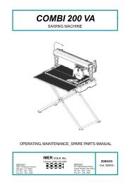
Fig.3.1<br />
The machine consists of a mobile cutting part (Fig.3.1-A), a fixed machine<br />
support frame (Fig.3.1-B), a disk cooling tank (Fig.3.1-C) and an adjustment<br />
unit (Fig.3.1-E).<br />
The machine is fitted with protection devices to guarantee maximum<br />
functioning safety (Fig.3.1-D).<br />
<br />
functions as follows:<br />
1. The piece to be machined is placed against the fence (Fig. 3.3 -E)<br />
of the work surface with the required angle using the protractor<br />
(Fig.3.1-E);<br />
2. Select the cutting angle, vertical (Fig.3.1) or tilted at 45° (Fig.3.3);<br />
to move the operating head to the fence, simply release the<br />
securing knob (Fig.3.1-F) (Fig.3.2-A) for the operating head angle<br />
setting, then secure the clamping knob again;<br />
<br />
<br />
<br />
<br />
<br />
<br />
The motor is driven by pressing the push-button on the handle (Fig.3.3/A).<br />
<br />
Electric motor characteristics<br />
115V-60Hz<br />
Power (Kw) 0.37<br />
Nominal voltage (V) 115<br />
Frequency (Hz) 60<br />
Number of poles 2<br />
R.p.m. 3430<br />
Isolation class<br />
S6<br />
Protection grade<br />
IP55<br />
Type of mechanical casing<br />
63 B14<br />
Capacitor (µF)<br />
35(D.36x90)<br />
<br />
<br />
<br />
Protection from machine noise ( symbol) in the workplace has been<br />
designed to meet the requirements of <br />
.<br />
<br />
<br />
<br />
<br />
<br />
<br />
<br />
Fig.3.2<br />
3. Turn the clamping knob for the operating head angle setting<br />
(Fig.3.1-G);<br />
4. Start up the machine using the maintained push-button near the<br />
handle (Fig.3.3-A).<br />
♦<br />
Make sure the tank is full of water during operations.<br />
5. Press the piece against the table by hand<br />
♦<br />
Apply a suitable pressure for the piece to be cut so that the motor<br />
is not overloaded (motor under normal operating conditions<br />
6. Move the operating unit and begin the cut; if the motor stops due to<br />
overloading, retract the disk from the workpiece and allow the<br />
motor to reach working speed before re-starting the cut.<br />
The cut must be made near the fences on the work table.<br />
♦<br />
If the 45° and 90° cuts are incorrect, adjust the screws on the two<br />
arms (Fig. 3.3.-F).<br />
A<br />
B<br />
<br />
<br />
<br />
Once the machine installation has been completed, machining can begin.<br />
consists of a stainless steel cutting surface. The 0.37 kW motor<br />
and the cutting head (work unit) are fitted on a steel bar tilted at 45° to ensure<br />
high cutting precision. The tile/stone cutter is placed on a tank, in plastic<br />
shock-proof material, which contains water. The tank can be easily removed<br />
for cleaning. There is a cooling pump immersed in the tank under the work<br />
table which supplies the water jet for cooling the cutting disk.<br />
3