Novel Hemispheric Image Formation: Concepts ... - ImmerVision
Novel Hemispheric Image Formation: Concepts ... - ImmerVision
Novel Hemispheric Image Formation: Concepts ... - ImmerVision

Create successful ePaper yourself
Turn your PDF publications into a flip-book with our unique Google optimized e-Paper software.
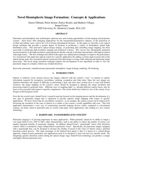
<strong>Novel</strong> <strong>Hemispheric</strong> <strong>Image</strong> <strong>Formation</strong>: <strong>Concepts</strong> & Applications<br />
Simon Thibault, Pierre Konen, Patrice Roulet, and Mathieu Villegas<br />
<strong>ImmerVision</strong><br />
2020 University St., Montreal, Canada H3A 2A5<br />
ABSTRACT<br />
Panoramic and hemispheric lens technologies represent new and exciting opportunities in both imaging and projection<br />
systems. Such lenses offer intriguing applications for the transportation/automotive industry, in the protection of<br />
civilian and military areas, and in the ever-evolving entertainment business. In this paper we describe a new optical<br />
design technique that provides a greater degree of freedom in producing a variety of hemispheric spatial light<br />
distribution areas. This innovative optical design strategy, of generating and controlling image mapping, has been<br />
successful in producing high-resolution imaging and projection systems. This success has subsequently generated<br />
increased interest in the high-resolution camera/projector and the concept of absolute measurement with high-resolution<br />
wide-angle lenses. The new technique described in this paper uses optimization techniques to improve the performance<br />
of a customized wide-angle lens optical system for a specific application. By adding a custom angle-to-pixel ratio at the<br />
optical design stage, this customized optical system provides ideal image coverage while reducing and optimizing signal<br />
processing. This novel image formation technique requires the development of new algorithms in order to view the<br />
panoramic image on a display without any residual distortion.<br />
Keywords: panoramic, omnidirectional, panomorph, hemispheric, image forming, rendering, 3D rendering.<br />
1. INTRODUCTION<br />
Natural or artificial vision systems process the images collected with the system’s “eyes” or cameras to capture<br />
information required for navigation, surveillance, tracking, recognition and other tasks. Since the way images are<br />
captured determines the degree of difficulty in performing a task, and since most systems have to cope with limited<br />
resources, the image mapping on the system’s sensor should be designed to optimize the image resolution and<br />
processing related to particular tasks. Different ways of sampling light, i.e., through different camera lenses, may be<br />
more or less powerful with respect to specific competencies. This seems intuitively evident in view of the variety of eye<br />
designs in the biological world.<br />
Over the last several years, <strong>ImmerVision</strong>’s research team has focused on the imaging process and the development of a<br />
new type of panoramic imager that is optimized to provide superior image mapping with respect to specific<br />
applications. We have shown that for surveillance scenarios 1 , as an example, the camera system can be improved by<br />
increasing the resolution in the zone of interest as it relates to the system’s overall capabilities and costs. This first<br />
application demonstrates a new way of constructing powerful imaging devices which, compared to conventional<br />
cameras, are better suited to particular tasks in various wide-angle vision applications, thus leading to a new camera<br />
technology.<br />
2. HARDWARE: PANOMORPH LENS CONCEPT<br />
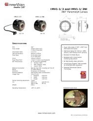
Panoramic imaging is of growing importance in many applications. While primarily valued for its ability to image a<br />
very large field-of-view (180 o X 360 o ), other characteristics, such as the ability to reduce the number of sensors, are<br />
equally important benefits of panoramic imaging. In addition, <strong>ImmerVision</strong>’s “panomorph” lenses offer distortion<br />
control, which is considered a major enhancement to panoramic vision 2 . Specifically, the panoramic imager, equipped<br />
with a panomorph lens, can be designed to increase the number of pixels in the zones of interest using a patented<br />
distortion-control process. The main advantage of the <strong>ImmerVision</strong> patent is that it is based on a custom-design<br />
approach, simply because panoramic lens applications need to be designed to meet real and very specific needs. By<br />
integrating specific distortion control during the optical design stage, <strong>ImmerVision</strong> technology can produce a unique<br />
and highly efficient panoramic lens.
The panomorph lens provides a full hemispheric field-of-view. In contrast with other types of panoramic imagers that<br />
suffer from blind zone (catadioptric cameras), low-image numerical aperture and high distortion, the panomorph lens is<br />
designed to use distortion as a design parameter, with the effect of producing a high-resolution coverage where needed,<br />
i.e., in the zone of interest.<br />
In the design of an efficient panoramic lens, the coverage area is divided into different zones. A specific resolution<br />
requirement as well as a particular field of view is defined for each individual zone. Figure 1 shows a typical<br />
surveillance scenario.<br />
Figure 1: Specific security zones.<br />
Figure 2: The ideal FOV (α) vs. the position (d) on the sensor for the scenario presented in Figure 1.<br />
For this particular scenario, the panoramic coverage area is divided into five adjacent and continuous zones. Zones B<br />
and C are symmetrical with the vertical axis. The five adjacent zones, while still providing full hemispheric coverage<br />
together, each feature a different resolution requirement, as the most significant objects are in Zone B. (Zone B in a<br />
surveillance application enables facial recognition and identification.) An object in Zone B is also more distant from the<br />
camera than an object in Zone A. This means that the relative angular resolution (pixels/degree) in Zones A and B<br />
should be different.<br />
For example: A human face in Zone B (located at 60 degrees from the vertical axis) will subtend an angle by half the<br />
amount that it would in Zone A (above the camera). To get the same number of pixels per face in both Zones A and B,<br />
the pixels/degree in Zone B must be twice the pixels/degree in Zone A. This means that the number of pixels required<br />
on the sensor to image Zone B is twice the number of pixels required to image Zone A.<br />
It is difficult to evaluate the exact resolution as a function of the sensor, because this would depend on the resolution<br />
chosen for the zone of interest. However, if we define i zones (1 to n) where each zone covers an angle (θ i ) with a<br />
number of pixels (N i ) we can describe the resolution (R i ) for each zone:
with the following limit conditions:<br />
R<br />
i<br />
N<br />
θ<br />
i<br />
= , (1)<br />
i<br />
n<br />
∑<br />
i=<br />
1<br />
N<br />
n<br />
i<br />
=∑ i i<br />
#<br />
i=<br />
1<br />
n<br />
i=<br />
1<br />
R ⋅θ = pixels . (2)<br />
and<br />
∑θ = θ<br />
i<br />
, (3)<br />
max<br />
showing that if you increase the resolution in the i zone, the result is less resolution in the other zones. In the next<br />
section we will see some examples of this.<br />
Table 1 summarizes how the modern distortion-corrected panomorph lens offers a real benefit over other types of<br />
panoramic imagers (with at least 180 degrees field-of-view). As a comparison matrix we used the following:<br />
The zone of interest is defined as 20 o to 60 o calculated under the horizon (0 degrees being the horizon), representing a<br />
typical zone of interest for a surveillance application. This comparison table is valid for any number of pixels on the<br />
sensor. The last column has been added to show the sensor footprint in viewing an interior scenario. As you can see,<br />
mirror, PAL and fisheye panoramic imagers use less than 60% of the sensor areas to image the FOV. In comparison,<br />
using anamorphic design, the panomorph lens uses up to 80% of the sensor to image the FOV, which is 30% more than<br />
any other panoramic imager on the market.<br />
Table 1: Panoramic image formation comparison<br />
Sensor surface<br />
used<br />
Pixels used<br />
in the zone<br />
of interest<br />
Blind<br />
zone<br />
Compactness<br />
Sensor Footprint<br />
Mirror <strong>Image</strong>r 57% 18% Yes No<br />
PAL<br />
(Panoramic Annular Lens)<br />
51% 28% Yes Yes<br />
Fisheye Lens 59% 29% No Yes
Panomorph Lens 79% 50% No Yes<br />
3. SOFTWARE: FROM PANORAMIC PICTURE TO STANDARD VISUALIZATION<br />
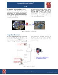
To be effective, the panoramic video-viewing library corrects image distortion from cameras equipped with a<br />
panomorph lens for display and control of one or more standard views, such as a PTZ (Figure 3) in real time. The<br />
viewing library allows simultaneous display of as many views as desired from one or more cameras (Figure 4).<br />
Figure 3: Real-time distortion-free display (left: original image produced by the panomorph lens).<br />
Figure 4: Four PTZ views (left), and two strips to display a 360° total camera surround in one single view (right).<br />
Consequently, the viewing process must unwrap the image in real time in order to provide views that reproduce real<br />
world proportions and geometrical information. The algorithms can be customized and adapted for each specific<br />
application, which is then related to human vision (display) or artificial vision (analytic function).<br />
The viewing process can be decomposed into three main steps:<br />
- the definition of the panomorph geometrical model (PGM) associated to each custom panomorph lens application;<br />
- the projection of the recorded image onto the PGM to provide a discretized mapping based on the recorded pixel<br />
position on the sensor;<br />
- finally, the rendering, which uses well-known standard rendering techniques.
3.1 Panomorph Geometrical Model (PGM)<br />
The image produced by each panomorph lens is unique to its application. The image mapping can be defined by a<br />
unique 3D geometrical model (Panomorph Geometrical Model, or PGM), which reproduces the panomorph lens design<br />
characteristics.<br />
The PGM is a geometric representation (surface) of the relative magnification of the lens as a function of the angles,<br />
expressed in spherical or polar coordinates (R, θ, φ). In other words, if the surface is represented by vector R, the length<br />
of the vector is proportional to the lens magnification (resolution) in the direction defined by the polar angles. This<br />
model depends on lens parameters such as the anamorphic ratio, the field of view, as well as position, size, and the<br />
magnification in the zones of interest.<br />
The PGM is a mathematical transformation of the image footprint I(u,v) into a surface S(R,θ,φ) representation using<br />
spherical coordinates:<br />
3.1.1 Anamorphic ratio<br />
I(u,v) S(R,θ,φ), (4)<br />
The anamorphic ratio is used only as a scale factor, which is function of the angle φ (Figure 5) This angle defines the<br />
azimuth direction of the recorded image taken by the panomorph lens.<br />
3.1.2 Field of view<br />
Figure 5 : Panomorph elliptical footprint I(u,v); scaling defined with φ angle.<br />
The field of view, or FOV, determines the angular limit (theta) of the PGM. The FOV of the panomorph lens is about<br />
180 degrees and can be more or less, depending on the application. Figure 6 shows two schematic PGMs with 180<br />
degree and 250 degree FOVs respectively.
Figure 6: PGM with 180 and 250 degree FOVs respectively.<br />
3.1.3 Distortion<br />
The panomorph lens uses distortion as a design parameter, in order to provide high-resolution coverage in a specific<br />
zone of interest. In other words, the FOV can be divided into different zones, each with a defined resolution, which all<br />
respect the equation 1 to 3. The characteristic of each zone is defined by its specific angular extension and relative<br />
resolution.<br />
To illustrate the impact of the distortion profile on the PGM, we will study two examples. In these examples, the FOV<br />
is 180 degrees wide, the zone of interest is 30 degrees wide, and the resolution is two times greater in the zone of<br />
interest than it is in the rest of the FOV (2:1). From one example to another, only the position of the zone of interest<br />
changes .<br />
Example 1:<br />
The first example is based on the design of a front view camera (Figure 7). In this case, the zone of interest is the central<br />
part of the image, even though the entire 180-degree FOV is still recorded. A panomorph lens with this feature can be<br />
used on a cell phone (for video conferencing) or on an ATM surveillance camera.<br />
Figure 7: Panomorph lens for a front-view camera.
The panomorph lens resolution in the central zone is twice that of the resolution in the periphery. Figure 8 shows the<br />
image footprint with the proper resolution for each zone. On the left of Figure 8, we have a Cartesian plot of the<br />
resolution as a function of the view angle (defined from the centre). We note that a transition zone exists between the<br />
central and the periphery areas. Theoretically, this transition can be very small, but as the panomorph lens is a real<br />
product, this transition can extend over 10 degrees.<br />
Figure 8: <strong>Image</strong> footprint (left) and resolution graph for the front-view panomorph lens.<br />
As defined, the PGM in the polar coordinate space represents the resolution of the panomorph lens, or a surface in space<br />
where the spatial resolution is constant in terms of azimuthal (θ ) direction. Mathematically, it means that the Cartesian<br />
graph (Figure 8, right side) is transposed into the spherical coordinate plane. Figure 9 shows the 3D PGM<br />
representation.<br />
Example 2:<br />
Figure 9: 3D PGM (left), 2D view in Y-Z plane.<br />
The second example demonstrates a panomorph lens optimized for video conferencing, where the zone of interest is not<br />
in the centre but on the edge of the field of view. Figures 10, 11 and 12 show the image footprint, the resolution and<br />
the corresponding PGM respectively.
Figure 10: Panomorph lens for video conferencing.<br />
Figure 11: <strong>Image</strong> footprint (left) and resolution graph (right) for the video-conferencing panomorph lens.<br />
3.1.4 Sensor resolution<br />
Figure 12: 3D PGM (left), 2D view in Y-Z plane (right).
A panomorph lens can be used with any sensor format (VGA, XGA, etc.) as long as the lens performance matches the<br />
Nyquist frequency of the sensor. The number of pixels will have an impact on the discretization of the model for the<br />
PGM. Up until now, the PGM has been defined by a continuous mathematical surface, however, on sensor we have a<br />
finite number of pixels.<br />
The continuous PGM will be sampled by the pixels. The number of pixels required to map the entire surface of the<br />
PGM is equal to the number of pixels on the sensor. Figure 13 shows a 2D sampling of the PGM using only 22<br />
elements. You should note that the pixel dimension is constant over the entire PGM, and the pixels are always<br />
perpendicular to the direction of regard (direction of the vector R). With a higher number of pixels, the discrete PGM<br />
will be closer to the continuous PGM, as shown in Figure 14.<br />
Figure 13: Discrete PGM with 22-unit (pixels) sample<br />
Figure 14: Discrete PGM with 44-unit (pixels) sample<br />
3.2 Projection of the panomorph image onto the PGM<br />
The image I (u,v) from the panomorph lens is projected onto the PGM, as shown in Figures 13 and 14. The final result<br />
is a discrete surface. The PGM is mapped with the panomorph image and can then be viewed using any classical 3D<br />
visualization techniques.<br />
Each pixel of the panomorph image is projected onto a discrete element of the PGM. The pixel position in the 3D space<br />
(on the surface) represents the real object position in the recorded scene. The projection uses the adapted azimuthal<br />
projection technique 4 with anamorphosis and distortion parameters added.<br />
3.3 Standard rendering of the PGM<br />
The final goal is to visualize the recorded scene without distortion. The PGM can be used to achieve this goal using a<br />
standard algorithm 3 . A virtual camera is placed at the central position (0,0,0). Viewing the scene with this virtual<br />
camera requires first selecting the angle (θ,φ) of viewing direction. Figure 15 shows two cameras pointing in two<br />
different directions. The camera pointed at the centre of the PGM will show a total of four elements (1D, 16 elements<br />
in 2D). The camera pointed at the edge of the PGM will show only two elements. This is the distortion effect. The<br />
resolution is twice in the centre than it is on the edge. A zoom can also be applied to change the ∆θ and provide virtual<br />
functionalities.
Figure 15: Virtual camera at the centre of the mapped PGM<br />
The following Figure 16 shows the final projection on a 2D plane of each virtual view. This 2D view can be sent to a<br />
display monitor.<br />
Figure 16: Viewing pixel as a function of the pointing direction of the virtual camera (left = centre, right =edge).<br />
4. CONCLUSION<br />
Panomorph lens development has led to a new type of panoramic imager that can be customized to enhance any<br />
panoramic imager application. The design features full hemispheric coverage, better use of sensor areas and increased<br />
resolution in the zone of interest. During the last decade, the <strong>ImmerVision</strong> research team has developed a custom<br />
viewing process perfectly adapted to the panomorph lens. The viewing process is composed of three steps. The first<br />
step is the definition of the panomorph geometrical model (PGM) associated with each custom panomorph lens<br />
application. The second step is the projection of the recorded image onto the PGM to provide a discretized mapping<br />
based on the recorded pixel position on the sensor. The third is a final rendering based on an azimuthal projection<br />
technique. The algorithms developed over the years have been optimized for use on small CPU and memory, enabling<br />
embedded processing. The algorithms are available thru a SDK running on Linux and Windows operating systems, and<br />
can be ported to many processors and systems.<br />
REFERENCES<br />
1. Thibault S. Enhanced Surveillance System Based on Panomorph Panoramic Lenses. Proc SPIE Vol. 6540, paper<br />
65400E, 2007.<br />
2. Thibault S. Distortion Control Offers Optical System Design a New Degree of Freedom. Photonics Spectra May<br />
2005, pp. 80-82.<br />
3. Radu HORAUD Olivier MONGA , Vision par Ordinateur - Outils fondamentaux, ,Ed. Hermès, 1995<br />
4. Weisstein, Eric W. "Azimuthal Equidistant Projection." From MathWorld--A Wolfram Web Resource.<br />
http://mathworld.wolfram.com/AzimuthalEquidistantProjection.html<br />
Formatted: French (France)
Authors contact:<br />
Simon Thibault M.Sc., Ph.D., P.Eng.<br />
Director, Optics Division & Principal Optical Designer<br />
<strong>ImmerVision</strong><br />
simon.thibault@immervision.com<br />
Patrice Roulet<br />
Technical Director<br />
<strong>ImmerVision</strong><br />
patrice.roulette@immervision.com