Panoramic Lens Applications Revisited - ImmerVision
Panoramic Lens Applications Revisited - ImmerVision
Panoramic Lens Applications Revisited - ImmerVision

Create successful ePaper yourself
Turn your PDF publications into a flip-book with our unique Google optimized e-Paper software.
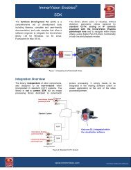
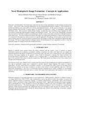
<strong>Panoramic</strong> <strong>Lens</strong> <strong>Applications</strong> <strong>Revisited</strong><br />
Simon Thibault * M.Sc., Ph.D., Eng<br />
Director, Optics Division/Principal Optical Designer<br />
<strong>ImmerVision</strong><br />
2020 University, Montreal, Quebec, H3A 2A5 Canada<br />
ABSTRACT<br />
During the last few years, innovative optical design strategies to generate and control image mapping have been<br />
successful in producing high-resolution digital imagers and projectors. This new generation of panoramic lenses<br />
includes catadioptric panoramic lenses, panoramic annular lenses, visible/IR fisheye lenses, anamorphic wide-angle<br />
attachments, and visible/IR panomorph lenses. Given that a wide-angle lens images a large field of view on a limited<br />
number of pixels, a systematic pixel-to-angle mapping will help the efficient use of each pixel in the field of view.<br />
In this paper, we present several modern applications of these modern types of hemispheric lenses. Recently,<br />
surveillance and security applications have been proposed and published in Security and Defence symposium.<br />
However, modern hemispheric lens can be used in many other fields. A panoramic imaging sensor contributes most to<br />
the perception of the world. <strong>Panoramic</strong> lenses are now ready to be deployed in many optical solutions. Covered<br />
applications include, but are not limited to medical imaging (endoscope, rigiscope, fiberscope…), remote sensing (pipe<br />
inspection, crime scene investigation, archeology…), multimedia (hemispheric projector, panoramic image…). Modern<br />
panoramic technologies allow simple and efficient digital image processing and the use of standard image analysis<br />
features (motion estimation, segmentation, object tracking, pattern recognition) in the complete 360o hemispheric area.<br />
Keywords: medical imaging, image analysis, immersion, omnidirectional, panoramic, panomorph, multimedia, total<br />
situation awareness, remote sensing, wide-angle<br />
1. INTRODUCTION<br />
Photography was invented by Daguerre in 1837, and at that time the main photographic objective was that the lens<br />
should cover a wide-angle field of view with a relatively high aperture 1 . However, these requirements were only<br />
satisfied after many years of development. Today, panoramic lens designers are facing the same challenge but with a<br />
different goal -- to efficiently control the image mapping to produce high performance digital imagers.<br />
The paper is mainly divided in two parts. We will first describe the evolution of the panoramic lens, we will not review<br />
everything but it gives a good understanding of this field. The second part will focus on the applications of modern<br />
panoramic imagers.<br />
2.1 The first immersive lens<br />
2. DEVELOPMENT OF MODERN PANORAMIC LENS<br />
Adding a large negative meniscus element mounted on the head of a compact positive component will create a system<br />
with a long back focal distance and a short focal length, which is namely a reversed telephoto. In the past, these types<br />
of lenses were very popular, since any lens used with a 35 mm camera had to have a back focal length of at least 35-40<br />
mm to clear the rocking mirror on the camera. Consequently, any lens with a focal length of less than approximately 40<br />
mm is a reversed telephoto type. Fortunately, this type is favourable for a wide-angle field of view. Wide-angle lenses<br />
are generally considered to be lenses with a field of view greater than 60 degrees.<br />
* simon.thibault@immervision.com; phone: +1 418-261-0049; www.immervision.com<br />
Optical and Digital Image Processing, edited by Peter Schelkens, Touradj Ebrahimi, Gabriel Cristóbal,<br />
Frédéric Truchetet, Proc. of SPIE Vol. 7000, 70000L, (2008) · 0277-786X/08/$18 · doi: 10.1117/12.781598<br />
Proc. of SPIE Vol. 7000 70000L-1
However, for angles larger than 100 degrees, the barrel distortion becomes difficult to correct. With an extended field<br />
of view, the reversed telephoto lens will cover a hemispherical field -- we will call such lens a fisheye lens. This lens is<br />
not really an extension of a wide-angle lens. The fisheye lens has inherent large distortion, but this distortion should not<br />
be considered an aberration but rather the result of the projection of a hemispheric field on a circle, which is not<br />
possible without distortion. <strong>Panoramic</strong> lenses are generally considered to be lenses with a field of view greater than 130<br />
degrees.<br />
2.2 Fish eye view<br />
The classical example of a fisheye lens “type” of image formation is an actual fish eye under water 2-3 . Robert W.<br />
Wood described in his book, Physical Optics (1911), a water-filled pinhole camera that was capable of simulating a<br />
fish’s view of the world (Figure 1A). Bond added a hemispheric lens with a pupil at the centre of the curvature in place<br />
of the water (Figure 1B). In 1924, Hill developed his Sky lens by adding a diverging meniscus lens (Figure 1C) before<br />
the hemispheric lens to improve the field curvature (thereby reducing the Peztval sum). This lens was a first prototype<br />
of the modern fisheye lenses (Figure 1D) which was patented by Schultz (1932) and Merté (1935). Some 40 years later,<br />
the now famous afocal wide-angle door viewer was patented 4 .<br />
A<br />
B<br />
C<br />
D<br />
Figure 1 A-D: Development of fisheye lens 2<br />
At that time a severe drawback was encountered when the fisheye was facing up or down, because in these positions the<br />
subject of interest might have appeared at the edge (large angle) of the field where the barrel distortion is very large.<br />
We will see later in this paper how the modern high-resolution lens design can now control this distortion, to improve<br />
the field coverage of a panoramic lens and solve this historical concern.<br />
2.3 Cylindrical panoramic view<br />
Motivated by the need to record a distortion-free panoramic image, the flat cylinder perspective was born 5 . The<br />
panoramic feature is different from the fisheye in that there is no longer imaging of a hemispheric field onto a circle, but<br />
instead a 360 o cylindrical field of view imaged onto a two-dimensional annular format (Figure 2). The annular image<br />
produced by such a geometrical transformation will not produce (theoretically) radial distortion (cylinder height);<br />
however, the horizontal (circle circumference) direction will suffer from compression, from the edge to the centre of the<br />
image plane.<br />
Proc. of SPIE Vol. 7000 70000L-2
I<br />
I<br />
II<br />
I ponoranic black r I<br />
I<br />
I<br />
si's<br />
v;deo cJero<br />
Figure 2: Flat cylinder perspective<br />
Figure 3: Optical arrangement proposed by Greguss<br />
There are many known panoramic viewing optical arrangements that use this cylinder perspective. In particular,<br />
Greguss’ patent 6 was one of the most promising approaches. Figure 3, which shows a block arrangement, is a copy of<br />
an actual drawing included in the patent. Rather than a fisheye, the panoramic block field-of-view is centred around a<br />
plane which is orthogonal to the optical axis at the expense of the on-axial imagery. This configuration allows a limited<br />
field-of-view in the radial direction (vertical in the field), where the imagery is relatively good to a first-order<br />
approximation.<br />
Another approach to getting a flat cylinder perspective is to rotate a conventional camera around the vertical axis. This<br />
technique requires several frames (with proper synchronization) for the camera to complete a full rotation. This method<br />
is useful and widely used today in the production of high-quality panoramic photography.<br />
2.4 Insect vision and Multi-lens camera<br />
Ideally, the goal in panoramic imaging is to be able to capture the entire scene in a single image from a single camera.<br />
This ideal imaging system would allow more than one hemisphere to be visible, similar to some insects’ vision system 7 .<br />
In reality, this can be achieved by using a multi-lens system with individual consecutive fields-of-view, totally covering<br />
a hemisphere 8 (Figure 4).<br />
Figure 4: Compound eye allow light to travel through several facts before striking the light sensitive surface.<br />
Proc. of SPIE Vol. 7000 70000L-3
2.5 Omnidirectional and catadioptric panoramic lens<br />
Reflective optics offer an alternative to panoramic imaging. A standard camera placed below a convex mirror will<br />
image a large field-of-view, the properties of which will depend on the shape of the reflective surface 9 . This approach<br />
has been used predominantly for producing panoramic TV displays. The projected images are captured by another<br />
equivalent optical arrangement (the reversibility property of light). For such an arrangement, the surface shape is not<br />
important as long as the projection mirror and the acquisition mirror are equivalent.<br />
Systems with spherical and conical mirrors have been used to capture wide-angle images for robotics and machine<br />
vision devices (omnidirectional vision system). The mirror shape design is important and can provide a global image<br />
on the sensor, which presents a polar image with elevation and azimuth linearly distributed to radius and angle<br />
respectively 9 .<br />
Recently Kweon et al 10 have developed a wide-angle catadioptric lens with a rectilinear projection scheme. The lens<br />
was designed for a miniature camera with a 1/3’’ colour CCD sensor (70 lp/mm) video graphics. The wide-angle lens<br />
will respect the relation between the pixel (r) and the angle (θ) as r = f tan θ as a standard camera lens. However the<br />
field-of-view is not a full hemisphere. The field-of-view of Kweon’s imager is limited to 151 degrees, and the<br />
distortion is less than 1%. The f-number is limited to 4.5, as the authors were not able to lower the f/number. Figure 5<br />
shows a photograph of the catadioptric lens and a sample video image.<br />
2.6 Modern Panomorph lens<br />
Figure 5: Photograph of the lens with the camera on a pole (left sample image).<br />
Modern panoramic lenses are able to add a distortion control which is considered a major enhancement in panoramic<br />
vision 11 . Specifically, the panoramic imager can be designed to increase the number of pixels in the zones of interest<br />
using a distortion control approach, which is a process patented by <strong>ImmerVision</strong>. The main benefit of the <strong>ImmerVision</strong><br />
patent is that it is based on a custom-designed approach, simply because the panoramic lens application should be<br />
designed to meet real and very specific needs. By including specific distortion during the optical design stage,<br />
<strong>ImmerVision</strong> can produce a very unique and more efficient panoramic lens.<br />
The Panomorph lens 12 uses this distortion control approach and an anamorphic image mapping to provide a unique full<br />
hemispheric field coverage. In contrast to other types of panoramic imagers that suffer from blind zone (catadioptric<br />
cameras), low-image numerical aperture and high distortion, the Panomorph lens uses distortion as a design parameter,<br />
in order to provide a high-resolution coverage where it is needed. It also features an anamorphic image mapping of the<br />
full hemispheric field, which produces an ellipse image footprint rather than a circle (or annular footprint) as do all<br />
other types of panoramic imagers. This feature provides an immediate 30% gain in pixels used on the sensor (the<br />
ellipse footprint matches the 4:3 ratio of a standard CCD or CMOS imager). The combination of distortion control and<br />
anamorphic design provides an important gain in resolution, and an advantage over all other types of panoramic<br />
imagers.<br />
Proc. of SPIE Vol. 7000 70000L-4
3. MODERN APPLICATIONS<br />
In the following section, we will present various applications that can benefit from the Panomorph technology. The<br />
main goal is always to view without distortion 360°X180° for total situational awareness. The main features of the<br />
Panomorph approach are:<br />
Pixel usage optimization in High Resolution and Low Resolution<br />
Reduced maintenance compared to mechanical PTZ mounting<br />
Low bandwidth compared to other panoramic technologies<br />
Fully customizable (optic and software)<br />
3.1 Security & Surveillance<br />
The advantages of panoramic imagers with high-image resolution include increased area coverage with a limited<br />
number of cameras, instantaneous detection, and location and tracking of multiple targets simultaneously. Adding<br />
incremental capabilities such as a visible, NIR or IR panomorph lens-based imager to an existing surveillance video<br />
system can provide improvements in operational efficiency and effectiveness 12 .<br />
<strong>Panoramic</strong> imagers offer a real 360-degree coverage of the surrounding area, valuable for a variety of surveillance,<br />
security and defence applications, including force protection, port security, perimeter security, site surveillance, border<br />
control, airport security, maritime operations, search and rescue, intrusion detection, and various others. Adding<br />
automatic detection, location, and tracking of targets ensures maximum protection, increases the protection system<br />
reliability and user confidence, and at the same time reduces the personnel workload.<br />
—<br />
IiJ<br />
Zone A<br />
Figure 6: Surveillance scenario.<br />
6x<br />
5)1<br />
4)1<br />
3)1<br />
2x<br />
1U 2P 3U 4U 5U 6U /U 8U UP<br />
Figure 7 : Image footprint with higher (+) resolution in the zone of interest for video surveillance scenario (right : the resolution<br />
distribution)<br />
Proc. of SPIE Vol. 7000 70000L-5
3.2 Projection & Immersive Systems<br />
Panomorph lens feature can also be used in projection systems. To project in a dome to produce immersive experience,<br />
the projected pixel of the DLP or SLM will use only a circular area of the active device making the other pixel obsolete.<br />
By using the Panomorph lens concept in particular the anamorphic correction we can display on the active device an<br />
elliptical area that pass through the Panomorph lens to project into a dome. Such approach will increase the number of<br />
projected pixel and will also provide more light on the screen. This make possible the use of HDTV projector for<br />
immersive experience.<br />
3.3 Biomedical & Inspection<br />
Figure 8: Immersive projection experience<br />
The Panomorph lens can be miniaturized in order to be installed on a cell phone or other very small device. For<br />
example, inspection fiberscope or endoscope can use a Panomorph lens to replace a standard limited FOV lens. This<br />
makes larger field of view available in very small zone where it is not possible to rotate the fiberscope.<br />
Right<br />
Up<br />
Eypi<br />
3.4 Automobile<br />
Figure 9: Fiberscope system for inspection<br />
In an automotive application, the benefits of panoramic technology might include "intelligent" airbag deployment, blind<br />
spot detection, automated or assisted parking, back-up warning systems, pedestrian detection, and lane departure<br />
warnings -- all accomplished with the use of a very limited number of sensors. For example: A single panoramic sensor<br />
flush-mounted on the front of a vehicle could provide all the information necessary for adaptive cruise control,<br />
pedestrian detection, lane-departure alerts and even lane following. A second panoramic sensor mounted on the back of<br />
the vehicle could provide all the information necessary for parking assistance, assisted overtaking of another vehicle (by<br />
Proc. of SPIE Vol. 7000 70000L-6
allowing a view of the other side of the road from a point of view different than the left rear-view mirror), back view,<br />
and others.<br />
As another example, an intelligent airbag system might combine seat-specific weight sensors with a stereo 2D overhead<br />
camera. Complex software is required to correlate the data from each sensor, and it may take additional devices to<br />
discriminate between a 70-lb. box and a 70-lb. child. The alternative is to build a consolidated system around a few or<br />
even a single panomorph optical sensor that can recognize and size (range) the object in the vehicle. Combining both<br />
ranging and recognition in a single, dedicated, small panomorph sensor will result in a practical imaging system that<br />
could potentially reduce the number of sensors required in the car. The same imaging sensor could also be used as a<br />
back-seat view camera (for child safety) or even as a anti-theft system that could view/record (pre-determined loop<br />
time) the entire inside area of the car. In fact, a rear, interior and forward-view single panomorph camera can handle a<br />
large number of applications simultaneously.<br />
Blind spot<br />
assistance<br />
Rear-view<br />
Smart Airbag<br />
Occupant<br />
classification<br />
Parking<br />
assistance<br />
3.5 Unmanned vehicle and Robotic<br />
Hooking-up<br />
Side-Views<br />
Trailer<br />
Parking Spot<br />
Measurement<br />
Mirror replacement<br />
Lane tracking<br />
departure warning<br />
Road sign<br />
detection<br />
Pre-crash<br />
safety<br />
Headlamp control<br />
Adaptive<br />
Cruise control<br />
Parking Block detection<br />
and Road Inspection<br />
Figure 10: Advance camera applications for automotive<br />
During the last decades, a lot of work have been done to provide efficient and effective navigation vision system.<br />
However, to make navigation decisions based on 360 degrees FOV is still today a subject of interest. However,<br />
standard panoramic imager has not provided a good solution. The Panomorph lens provides an efficient alternative.<br />
Four other applications can be made with such 220 o x 360 o FoV Panomorph lens configuration and will allow total<br />
situation awareness system with a reduced number of sensors:<br />
• Remote and automatic navigation<br />
• 3D vision and 3D reconstruction<br />
• Secondary Targets detection and tracking: Using distortion management algorithms (provided in<br />
<strong>ImmerVision</strong>’s SDK), it is possible to generate a virtual unwarped view (Undistorted 2D view)<br />
around each detected target in the hemispheric FoV. Each of the view would track/follow each<br />
detected target allowing operator to qualify.<br />
• Primary Target detection and tracking: image fusion between high resolution PTZ camera and the<br />
panomorph camera would allow an operator to better qualify primary target and still keep/track<br />
secondary target in the full hemispheric FoV,<br />
Proc. of SPIE Vol. 7000 70000L-7
Figure 11: Robot and unmanned vehicle system.<br />
An IR panoramic system can also be used for driving ground vehicles in darkness or conditions of limited visibility,<br />
since it provides a field of view similar to that of the human eye and is therefore intuitively more user-friendly.<br />
Mounted on top of a vehicle it can be used to see events in darkness and the activity all around the vehicle, including<br />
people and other life forms, objects, and activities. It can also be used to see around ships to detect threats or to follow<br />
activities in progress.<br />
5. CONCLUSION<br />
We have discussed the current developments in panoramic imager design by providing an historical perspective from<br />
the reversed telephoto to the new controlled-distortion lenses such as the panomorph lens. Modern panomorph lenses<br />
which provide a distortion control approach and an anamorphic design are considered a major enhancement in<br />
panoramic vision. We have presented various current scenarios where a high-resolution panoramic imager will be most<br />
advantageous. In a sense, this a new age for <strong>Panoramic</strong> applications.<br />
Over the last several years, <strong>ImmerVision</strong>’s research team has focused on the imaging process and the development of a<br />
new type of panoramic imager that is optimized to provide superior image mapping with respect to specific<br />
applications. The recent development in panoramic vision system created a new interest for the research and<br />
technology field. We will focus during the next years on the technology development to produce new generation of<br />
panoramic imager using most recent digital camera (MPxs), IR FPA and miniature systems. In the mid time, we<br />
develop simulation tools that can provide the virtual system performance before fabrication. Such unique tools can be<br />
used to determine and orient future development.<br />
REFERENCES<br />
[1]<br />
[2]<br />
[3]<br />
[4]<br />
[5]<br />
[6]<br />
[7]<br />
[8]<br />
[9]<br />
[10]<br />
[11]<br />
[12]<br />
Kingslake R. Development of the photographic objective. Proc SPIE Vol. 0531, pp. 60-67, 1985<br />
Miyamoto K. Fish Eye <strong>Lens</strong>, Letters to the Editor. JOSA, Vol. 54, pp. 1060-1061, 1964.<br />
Kumler J, Bauer M. Fisheye lens design and their relative performance. Proc SPIE Vol. 4093, pp. 360-369, 2000.<br />
US Patent 4,082,434. Wide-angle optical system for door viewer, issued to T. Hiyashi, September 4, 1978.<br />
Greguss, Pal. <strong>Panoramic</strong> Security. SPIE Vol. 1509, pp. 55-66 (1991).<br />
Greguss P. <strong>Panoramic</strong> imaging block for three-dimensional space. US Patent 4,566,763 (28 January 1986).<br />
Horridge GA. The compound eye of insects. Sci Am Iss. 237, p 108-120, July 1977.<br />
A. N de Jong and P.B.W. Schwering, IR panoramic alerting sensor concepts and applications, Proc SPIE 5074,<br />
658-668 (2003).<br />
Chahl JS and Srinivasan MV. Reflective surfaces for panoramic imaging. Applied Optics Vol. 36, No. 31, pp. 8275-<br />
8285.<br />
Kweon G, Hwang-bo S, Kim G-h, Yang S-c and Lee Y-h. Wide-angle catadioptric lens with a rectilinear projection<br />
scheme. Applied Optics Vol. 45, No. 34, pp. 8659-8673.<br />
Thibault S. Distortion Control Offers Optical System Design a New Degree of Freedom. Photonics Spectra May<br />
2005, pp. 80-82.<br />
Thibault S. Enhanced Surveillance System Based on Panomorph <strong>Panoramic</strong> <strong>Lens</strong>es. Proc SPIE Vol. 6540, paper<br />
65400E, 2007.<br />
Proc. of SPIE Vol. 7000 70000L-8