CASMED 740 Vital Signs Monitor - Implox
CASMED 740 Vital Signs Monitor - Implox
CASMED 740 Vital Signs Monitor - Implox

Create successful ePaper yourself
Turn your PDF publications into a flip-book with our unique Google optimized e-Paper software.
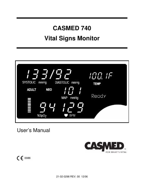
<strong>CASMED</strong> <strong>740</strong><br />
<strong>Vital</strong> <strong>Signs</strong> <strong>Monitor</strong><br />
User’s Manual<br />
21-02-0298 REV. 00 12/06
2<br />
21-02-0298 REV. 00 12/06
THE <strong>CASMED</strong> <strong>740</strong><br />
VITAL SIGNS MONITOR<br />
FEATURES<br />
<strong>CASMED</strong> <strong>740</strong> - 1<br />
Non-Invasive Blood Pressure and Pulse Rate.<br />
<strong>CASMED</strong> <strong>740</strong> - 2 Non-Invasive Blood Pressure, Pulse Rate and Pulse<br />
Oximeter.<br />
or<br />
Non-Invasive Blood Pressure, Pulse Rate and Temperature.<br />
<strong>CASMED</strong> <strong>740</strong> - 3<br />
<strong>Vital</strong> <strong>Signs</strong> <strong>Monitor</strong> with Non-Invasive Blood Pressure,<br />
Pulse Rate, Pulse Oximeter and Predictive Temperature.<br />
IMPORTANT:<br />
This manual addresses all parameters of the <strong>CASMED</strong> <strong>740</strong><br />
<strong>Vital</strong> <strong>Signs</strong> <strong>Monitor</strong>. You may have purchased a model that<br />
does not have all the parameters referred to in the manual.<br />
THIS MANUAL REMAINS SUITABLE FOR USE!<br />
Please refer to sections of the manual and the Quick<br />
Reference Guide that are applicable for the model purchased.<br />
WARNING:<br />
The <strong>CASMED</strong> <strong>740</strong> <strong>Monitor</strong> is to be operated by qualified<br />
personnel only. Before use, carefully read this manual,<br />
including accessory directions for use, all precautionary<br />
information, and specifications. The user must check that<br />
the equipment functions safely and see that it is in proper<br />
working condition before being used.<br />
21-02-0298 REV. 00 12/06<br />
3
In the U.S. the following Caution applies:<br />
CAUTION:<br />
Federal law restricts this device to sale by or on<br />
the order of a physician or properly licensed<br />
practitioner.<br />
First Printing: 12/2006<br />
4<br />
21-02-0298 REV. 00 12/06
INITIAL SETUP<br />
Before using the monitor for the first time, the following items should be<br />
performed:<br />
• Select the operating Language<br />
• Select the Temperature scale (if installed)<br />
• Set the monitor’s Date and Time<br />
These items are found in the monitor’s Configuration Menu.<br />
To enter the Configuration Menu, press and hold the ALARM LIMITS<br />
and VOLUME push button keys while turning “ON” the unit.<br />
NOTE:<br />
Unit will beep once and software version will be displayed.<br />
Steps must be completed within 60 seconds or process must be restarted.<br />
Language<br />
Press until the menu for language is displayed. Press either or to make your selection.<br />
Temperature Scale (if installed)<br />
Press until the menu for temperature scale is displayed. Press either or to make your<br />
selection.<br />
Date<br />
Press until the date is displayed. The day parameter is flashing. Press either or to change<br />
the Day.<br />
Press one time. Press either or to change the Month.<br />
Press one time. Press either or to change the Year.<br />
Time<br />
Press one time. Press either or to change the Hour.<br />
Press one time. Press either or to change the Minute.<br />
Press<br />
one time to exit and save your changes.<br />
21-02-0298 REV. 00 12/06<br />
5
This page is intentionally left blank<br />
6<br />
21-02-0298 REV. 00 12/06
Manufacturers Declaration of Conformity<br />
Electronic Emissions and Immunity<br />
The Model <strong>740</strong> <strong>Monitor</strong> is intended for use in the electromagnetic environment specified below. The<br />
customer or the user of the Model <strong>740</strong> <strong>Monitor</strong> should assure it is used in such an environment.<br />
Emissions Test Compliance Electromagnetic Environment<br />
RF emissions – CISPR 11 Group 1 The Model <strong>740</strong> <strong>Monitor</strong> uses RF energy only for its internal<br />
function. Therefore, its RF emissions are very low and are<br />
not likely to cause any interference in nearby electronic<br />
equipment.<br />
RF emissions – CISPR 11<br />
Harmonic emissions<br />
IEC 61000-3-2<br />
Voltage fluctuations /<br />
flicker emissions<br />
Class B<br />
Class B<br />
Complies<br />
The Model <strong>740</strong> <strong>Monitor</strong> is suitable for use in all<br />
establishments, including domestic establishments and<br />
those directly connected to the public low-voltage power<br />
supply network that supplies buildings used for domestic<br />
purposes.<br />
Immunity Test IEC 60601 Test Level Compliance Level Electromagnetic Environment<br />
Guidance<br />
Electrostatic +/-6 kV contact +/-6 kV contact Floors should be wood concrete<br />
discharge (ESD) +/-8 kV air<br />
+/-8 kV air<br />
or ceramic tile. If floors are<br />
IEC 61000-4-2<br />
covered with synthetic material,<br />
the relative humidity should be at<br />
Electrical fast<br />
transient/burst<br />
IEC 61000-4-4<br />
Surge<br />
IEC 61000-4-5<br />
Voltage Dips,<br />
short interruptions<br />
and voltage<br />
variations on<br />
power supply<br />
input lines<br />
IEC 61000-4-11<br />
Power frequency<br />
(50/60 Hz)<br />
magnetic field<br />
IEC 61000-4-8<br />
+/-2 kV for power<br />
supply lines<br />
+/-1 kV for input/output<br />
lines<br />
+/-1 kV differential<br />
mode<br />
+/-2 kV common mode<br />
< 5% U T (>95% dip in<br />
U T ) for 0.5 cycle.<br />
40% U T (60% dip in<br />
U T ) for 5 cycles.<br />
70% U T (30% dip in<br />
U T ) for 25 cycles.<br />
< 5% U T (> 95% dip in<br />
U T ) for 5 seconds.<br />
least 30%.<br />
Mains power quality should be<br />
that of a typical commercial or<br />
hospital environment.<br />
Mains power quality should be<br />
that of a typical commercial or<br />
hospital environment.<br />
Mains power quality should be<br />
that of a typical commercial or<br />
hospital environment. If user of<br />
the Model <strong>740</strong> <strong>Monitor</strong> requires<br />
continued operation during power<br />
mains interruptions, it is<br />
recommended that the Model <strong>740</strong><br />
<strong>Monitor</strong> be powered from an<br />
uninterruptible power supply or a<br />
battery.<br />
3 A/m 3 A/m Power frequency magnetic fields<br />
should be at levels characteristic<br />
of a typical location in a typical<br />
commercial or hospital<br />
environment.<br />
NOTE: U T is the A.C. mains voltage prior to application of the test level.<br />
21-02-0298 REV. 00 12/06<br />
7
Guidance and Manufacturer’s Declaration – Electromagnetic Immunity<br />
The Model <strong>740</strong> <strong>Monitor</strong> is intended for use in the electromagnetic environment specified below. The customer or the user of the<br />
Model <strong>740</strong> <strong>Monitor</strong> should insure that it is used in such an environment.<br />
Immunity Test IEC 60601 Test Level Compliance<br />
Level<br />
Electromagnetic Environment - Guidance<br />
Portable and mobile RF communications equipment<br />
should be used no closer to any part of the Model <strong>740</strong><br />
<strong>Monitor</strong>, including cables, than the recommended<br />
separation distance calculated from the equation<br />
applicable to the frequency of the transmitter.<br />
Recommended separation distance:<br />
Conducted RF<br />
IEC 61000-4-6<br />
3 Vrms<br />
150 kHz to 80 MHz<br />
3 Vrms<br />
d = 1.2√P<br />
Radiated RF<br />
IEC 61000-4-3<br />
3 V/m<br />
80 MHz to 2.5 GHz<br />
3 V/m<br />
d = 1.2√P 80 MHz to 800 MHz<br />
d = 2.3√P 800 MHz to 2.5 GHz<br />
Where P is the maximum output power rating of the<br />
transmitter in watts according to the transmitter<br />
manufacturer and d is the recommended separation<br />
distance in meters.<br />
Field strengths from fixed RF transmitters, as<br />
determined by an electromagnetic site survey a ,<br />
should be less than the compliance level in each<br />
frequency range. b<br />
Interference may occur in the vicinity of equipment<br />
marked with the following symbol:<br />
NOTE 1 At 80 MHz and 800 MHz, the higher frequency range applies.<br />
NOTE 2 These guidelines may not apply in all situations. Electromagnetic propagation is effected by absorption and reflection from<br />
structures, objects and people.<br />
a Field strengths from fixed transmitters, such as base stations for radio (cellular / cordless) telephones and land mobile radios,<br />
amateur radio, AM and FM radio broadcast and TV broadcast cannot be predicted theoretically with accuracy. To assess the<br />
electromagnetic environment due to fixed RF transmitters, an electromagnetic site survey should be considered. If the measured<br />
field strength in the location in which the Model <strong>740</strong> <strong>Monitor</strong> is used exceeds the applicable RF compliance level above, the Model<br />
<strong>740</strong> <strong>Monitor</strong> should be observed to verify normal operation. If abnormal performance is observed, additional measures may be<br />
necessary, such as re-orienting or relocating the Model <strong>740</strong> <strong>Monitor</strong>.<br />
b<br />
Over the frequency range 150 kHz to 80 MHz, field strengths should be less than 3 V/m.<br />
Recommended Separation Distances Between Portable and Mobile RF Communications Equipment and the<br />
Model <strong>740</strong> <strong>Monitor</strong><br />
The Model <strong>740</strong> <strong>Monitor</strong> is intended for use in an electromagnetic environment in which radiated RF disturbances are controlled. The<br />
customer or the user of the Model <strong>740</strong> <strong>Monitor</strong> can help prevent electromagnetic interference by maintaining a minimum distance<br />
between portable and mobile RF communications equipment (transmitters) and the Model <strong>740</strong> <strong>Monitor</strong> as recommended below,<br />
according to the maximum output power of the communications equipment.<br />
Separation distance according to frequency of transmitter (Meters)<br />
Rated maximum output<br />
power of transmitter<br />
(Watts)<br />
150 kHz to 80 MHz<br />
d = 1.2√P<br />
80 MHz to 800 MHz<br />
d = 1.2√P<br />
800 MHz to 2.5 GHz<br />
d = 2.3√P<br />
0.01 0.12 0.12 0.23<br />
0.1 0.38 0.38 0.73<br />
1 1.2 1.2 2.3<br />
10 3.8 3.8 7.3<br />
100 12 12 23<br />
For transmitters operating at a maximum output power not listed above, the recommended separation distance d in meters can be<br />
estimated using the equation applicable to the frequency of the transmitter, where P is the maximum output power rating of the<br />
transmitter in watts according to the transmitter manufacturer.<br />
NOTE 1 At 80 MHz and 800 MHz, the separation distance for the higher frequency range applies.<br />
NOTE 2 These guidelines may not apply in all situations. Electromagnetic propagation is affected by absorption and reflection from<br />
structures, objects and people.<br />
8<br />
21-02-0298 REV. 00 12/06
WARRANTY POLICY<br />
MONITOR (<strong>CASMED</strong> <strong>740</strong>)<br />
NOTE:<br />
For all U.S. government accounts please see the Warranty Addendum at www.va.casmed.com.<br />
All products are sold by CAS Medical Systems, Inc. under the warranties set forth in the<br />
following paragraphs. Such warranties are extended only with respect to the purchase of this<br />
product directly from CAS Medical Systems, Inc. or CAS’s Authorized Distributors as new<br />
merchandise and are extended to the first buyer thereof, other than for resale.<br />
The <strong>CASMED</strong> <strong>740</strong> <strong>Monitor</strong> is warranted for a period of twenty-four (24) months. All products,<br />
excluding printers, if applicable, are warranted to be free from functional defects in materials and<br />
workmanship and to conform to the description of the product contained in the Operator/Service<br />
Manual, published specifications, and accompanying labels and/or inserts, provided that the<br />
same is properly operated under conditions of normal use in accordance with applicable safety<br />
and regulatory requirements, and that replacements and repairs are made in accordance with<br />
the instructions provided by CAS Medical Systems, Inc.<br />
The same warranty conditions are made for a period of twelve (12) months with respect to<br />
printer and battery. A ninety (90) days warranty is provided for non-disposable accessories such<br />
as reusable SpO 2 sensors, reusable temperature probes and other accessories provided by<br />
CAS as part of the original purchase. CAS warrants disposable or single-patient-use products,<br />
including blood pressure cuffs, for out-of-box failure only. Reusable blood pressure cuffs are<br />
warranted for one year. Where the accessory is not a CAS Medical Systems, Inc. manufactured<br />
product, the manufacturer’s own warranty applies. Warranty of accessories purchased<br />
separately from listed suppliers will be the responsibility of such listed suppliers. Damage to any<br />
part through misuse, neglect, or accident, or by affixing any accessories or attachments other<br />
than CAS, Statcorp, Masimo®, Nellcor®, Nonin®, and Welch Allyn® manufactured accessories<br />
or attachments, is not covered by this warranty.<br />
The foregoing warranties shall not apply if the product has been configured, modified, adjusted<br />
or repaired other than by CAS Medical Systems, Inc. or by persons expressly authorized by CAS<br />
Medical Systems, Inc., or not in accordance with written instructions provided by CAS Medical<br />
Systems, Inc., or if the product has been subjected to misuse, negligence, or accident. This<br />
warranty is void if the printer is used with any paper other than that specified by CAS Medical<br />
Systems, Inc.<br />
21-02-0298 REV. 00 12/06<br />
9
CAS reserves the right to perform warranty service operations in its own factory, at an authorized<br />
repair facility, or at the customers’ site. CAS Medical Systems, Inc.’s sole and exclusive<br />
obligation and Buyer’s sole and exclusive remedy under the above warranties, is limited to<br />
repairing or replacing, free of charge, a product which is reported in writing or via telephone to<br />
CAS Medical Systems, Inc., has a Return Material Authorization (RMA) number assigned and<br />
which is returned during normal business hours, transporting charges prepaid to:<br />
CAS Medical Systems, Inc.<br />
44 East Industrial Road<br />
Branford, CT. 06405 USA<br />
Telephone: +1 203 488 6056<br />
Fax: +1 203 488 9438<br />
E-mail: custsrv@casmed.com<br />
CAS MEDICAL SYSTEMS, INC. SHALL NOT BE OTHERWISE LIABLE FOR ANY DAMAGES<br />
INCLUDING, BUT NOT LIMITED TO, INCIDENTAL DAMAGES, CONSEQUENTIAL DAMAGES<br />
OR SPECIAL DAMAGES.<br />
THERE ARE NO EXPRESS OR IMPLIED WARRANTIES WHICH EXTEND BEYOND THE<br />
WARRANTIES HEREINABOVE SET FORTH. CAS MEDICAL SYSTEMS, INC. MAKES NO<br />
WARRANTY OF MERCHANTABILITY OR FITNESS FOR A PARTICULAR PURPOSE WITH<br />
RESPECT TO THE PRODUCT OR PARTS THEREOF.<br />
10<br />
21-02-0298 REV. 00 12/06
HOW TO CONTACT US<br />
Authorized Representative in European<br />
Union:<br />
CAS Medical Systems, Inc<br />
Mossa Consulting GmbH<br />
44 East Industrial Road Bollbrügg 22<br />
Branford, CT 06405<br />
23570 Lübeck<br />
U.S.A.<br />
Germany<br />
Phone:<br />
Phone:<br />
(800) 227-4414 +49-4502-880-557<br />
(203) 488-6056<br />
Fax:<br />
Fax:<br />
(203) 488-9438 +49-4502-880-559<br />
E-Mail:<br />
custsrv@casmed.com<br />
sales@casmed.com<br />
techsrv@casmed.com<br />
Web:<br />
www.casmed.com<br />
E-Mail:<br />
mossa.rod@t-online.de<br />
Should service be required, contact the<br />
dealer in the country of purchase.<br />
Copyright 2003 CAS Medical Systems, Inc.<br />
All rights reserved. No part of this manual may be reproduced without the written<br />
permission of CAS Medical Systems, Inc. CAS reserves the right to make changes to this<br />
manual and improvements to the product it describes at any time without notice or<br />
obligation.<br />
21-02-0298 REV. 00 12/06<br />
11
This page is intentionally left blank<br />
12<br />
21-02-0298 REV. 00 12/06
TABLE OF CONTENTS<br />
<strong>CASMED</strong> <strong>740</strong> <strong>Monitor</strong>s<br />
1. INTRODUCTION AND INTENDED USE........................................................ 21<br />
INTRODUCTION ...................................................................................................... 21<br />
INDICATIONS FOR USE.......................................................................................... 21<br />
CONTRAINDICATIONS ........................................................................................... 21<br />
BRIEF DEVICE DESCRIPTION ............................................................................... 21<br />
PATIENT ENVIRONMENT....................................................................................... 23<br />
DEFINITION OF TERMS.......................................................................................... 24<br />
2. UNPACKING THE MONITOR........................................................................ 27<br />
INITIAL INSPECTION............................................................................................... 27<br />
MONITOR CHECKLIST............................................................................................ 27<br />
OPTIONAL MOUNTING ACCESSORIES................................................................ 28<br />
3. SYMBOLS...................................................................................................... 31<br />
4. SAFETY MEASURES AND WARNINGS....................................................... 39<br />
AUTOMATIC SAFETY FEATURES ......................................................................... 43<br />
5. BLOOD PRESSURE MONITORING.............................................................. 47<br />
CUFF SELECTION AND APPLICATION................................................................. 47<br />
NIBP HOSES ............................................................................................................ 49<br />
6. PULSE OXIMETRY MONITORING................................................................ 53<br />
TAKING A SpO 2 MEASUREMENT .......................................................................... 53<br />
FINGER CLIP SENSORS......................................................................................53<br />
DISPOSABLE FLEX - TYPE SENSORS ..............................................................54<br />
MASIMO® OXIMETER (if so equipped)................................................................... 55<br />
ATTACHING THE CABLES ..................................................................................55<br />
REMOVING THE INTERFACE CABLE ................................................................56<br />
MASIMO MESSAGES ...........................................................................................56<br />
NELLCOR® OXIMETER (if so equipped) ................................................................ 57<br />
ATTACHMENT PROCEDURE..............................................................................57<br />
REMOVING THE INTERFACE CABLE ................................................................57<br />
NONIN® OXIMETER (if so equipped)...................................................................... 58<br />
ATTACHING THE SENSOR CABLE ....................................................................58<br />
REMOVING THE SENSOR CABLE......................................................................58<br />
7. TEMPERATURE MONITORING .................................................................... 61<br />
WELCH ALLYN TEMPERATURE............................................................................ 61<br />
TAKING AN ORAL TEMPERATURE....................................................................61<br />
TAKING A RECTAL TEMPERATURE ..................................................................63<br />
TAKING AN AXILLARY TEMPERATURE.............................................................65<br />
INSERTING & REMOVING PROBE WELL (SureTemp Plus® Only) ..................67<br />
21-02-0298 REV. 00 12/06<br />
13
<strong>CASMED</strong> <strong>740</strong> <strong>Monitor</strong>s<br />
8. MONITOR OPERATION ................................................................................ 71<br />
FRONT PANEL......................................................................................................... 71<br />
DIGITAL DISPLAY AND INDICATORS ................................................................72<br />
FRONT PANEL CONTROLS ................................................................................74<br />
INFRARED (Ir) DATA PORT .................................................................................77<br />
REAR PANEL ........................................................................................................... 78<br />
AC / DC CONNECTION ........................................................................................79<br />
FUSE COMPARTMENT........................................................................................79<br />
BATTERY COMPARTMENT.................................................................................79<br />
TEMPERATURE PROBE ELECTRICAL CONNECTION.....................................79<br />
EQUIPOTENTIALITY GROUND POST ................................................................80<br />
EXTERNAL DEVICE INTERFACE........................................................................80<br />
LEFT SIDE VIEW ..................................................................................................... 80<br />
CUFF HOSE CONNECTION.................................................................................81<br />
SpO 2 SENSOR CONNECTION.............................................................................81<br />
RIGHT SIDE VIEW ................................................................................................... 82<br />
TEMPERATURE HOLDER ...................................................................................82<br />
MONITOR OPERATING INSTRUCTIONS .............................................................. 83<br />
ADULT/ NEONATE OPERATING MODE .............................................................83<br />
TURNING THE <strong>CASMED</strong> <strong>740</strong> MONITOR “ON” ...................................................83<br />
FRONT PANEL INTENSITY CONTROL...............................................................85<br />
DISPLAYING THE TIME .......................................................................................85<br />
MANUAL MODE FOR BLOOD PRESSURE DETERMINATION .........................85<br />
AUTOMATIC CYCLE FOR BLOOD PRESSURE DETERMINATION..................87<br />
STAT MODE..........................................................................................................87<br />
HISTORY MODES.................................................................................................... 88<br />
EVENT HISTORY (EVENT-Ev).............................................................................89<br />
TREND HISTORY (TREND-Tr).............................................................................90<br />
PRINT HISTORY ...................................................................................................90<br />
CLEARING HISTORY ...........................................................................................91<br />
REAL TIME CLOCK (RTC) ...................................................................................91<br />
PATIENT ALARM MODE ......................................................................................... 91<br />
CHANGING ALARM LIMITS .................................................................................92<br />
SAVING ALARM LIMITS .......................................................................................92<br />
RESTORE FACTORY DEFAULTS.......................................................................92<br />
ALARM LIMIT VALUES.........................................................................................93<br />
AUDIBLE AND VISUAL INDICATORS .................................................................94<br />
CLEARING ALARMS.............................................................................................95<br />
NIBP PATIENT ALARMS .................................................................................95<br />
HIGH / LOW %SpO 2 ALARMS .........................................................................95<br />
SpO 2 PULSE RATE ALARM.............................................................................95<br />
EQUIPMENT ALARMS.....................................................................................96<br />
ADJUSTING THE AUDIO ALARM VOLUME........................................................96<br />
ADJUSTING THE SpO 2 “BEEP” VOLUME ...........................................................96<br />
2-MINUTE AUDIO SILENCE.................................................................................96<br />
PERMANENT AUDIO ALARM SILENCE..............................................................97<br />
ALARM LIMITS OFF..............................................................................................98<br />
14<br />
21-02-0298 REV. 00 12/06
<strong>CASMED</strong> <strong>740</strong> <strong>Monitor</strong>s<br />
MONITOR CONFIGURATION ................................................................................. 98<br />
ENTERING THE CONFIGURATION MENU.........................................................98<br />
SAVING YOUR CHANGES...................................................................................99<br />
SOFTWARE REVISIONS .....................................................................................99<br />
SELECTING THE LANGUAGE.............................................................................100<br />
SELECTING THE PATIENT MODE......................................................................100<br />
SELECTING THE POWER-OFF DELAY TIME ....................................................101<br />
SELECTING THE TEMPERATURE SCALE.........................................................101<br />
AUDIO ALARM SILENCE (SILENCE/RESET Pushbutton)..................................101<br />
2-MINUTE AUDIO ALARM SILENCE...............................................................102<br />
PERMANENT AUDIO ALARM SILENCE.........................................................102<br />
ALARM LIMITS OFF.........................................................................................102<br />
MAP VALUE ENABLE / DISABLE.........................................................................103<br />
SET THE SpO 2 ALARM DELAY............................................................................103<br />
SETTING THE DATE ............................................................................................104<br />
SETTING THE TIME .............................................................................................104<br />
DAYLIGHT SAVING TIME OPTION......................................................................105<br />
BATTERY POWER................................................................................................... 105<br />
CHECKING BATTERY STATUS...........................................................................107<br />
AUTO OFF FEATURE.............................................................................................. 108<br />
POWER FAIL............................................................................................................ 108<br />
USER MESSAGES................................................................................................... 108<br />
SpO 2 USER MESSAGES ......................................................................................109<br />
TEMPERATURE FUNCTION USER MESSAGES ...............................................110<br />
ERROR MESSAGES ON THE MESSAGE WINDOW .........................................113<br />
9. EXTERNAL PRINTER.................................................................................... 119<br />
PRINTER OVERVIEW ............................................................................................. 119<br />
PRINTER CONTROLS AND INDICATORS............................................................. 120<br />
PRINTER OPERATION............................................................................................ 121<br />
DIRECT CONNECTION ........................................................................................121<br />
INFRARED CONNECTION ...................................................................................121<br />
CHARGING THE PRINTER BATTERY ................................................................... 123<br />
INSTALLING PAPER................................................................................................ 123<br />
REPLACING THE BATTERY PACK ........................................................................ 124<br />
INSTALLING A NEW BATTERY PACK ................................................................... 125<br />
10. CLEANING..................................................................................................... 129<br />
CLEANING OVERVIEW ........................................................................................... 129<br />
THE MONITOR......................................................................................................129<br />
THE DISPLAY........................................................................................................130<br />
CUFFS ...................................................................................................................130<br />
TUFF-CUFF ......................................................................................................130<br />
SAFE-CUFF......................................................................................................130<br />
SOFTCHECK....................................................................................................130<br />
ULTRACHECK..................................................................................................130<br />
PNEUMATIC TUBING...........................................................................................131<br />
PRINTER ...............................................................................................................131<br />
21-02-0298 REV. 00 12/06<br />
15
<strong>CASMED</strong> <strong>740</strong> <strong>Monitor</strong>s<br />
SpO 2 INTERCONNECT CABLE............................................................................131<br />
SpO 2 SENSORS....................................................................................................131<br />
TEMPERATURE PROBES ...................................................................................132<br />
PROBE WELL (SureTemp Plus)...........................................................................132<br />
11. MAINTENANCE ............................................................................................. 135<br />
MAINTENANCE INTERVALS .................................................................................. 135<br />
TEST MODE ............................................................................................................. 135<br />
ENTER THE TEST MODE ....................................................................................... 135<br />
EXIT THE TEST MODE............................................................................................ 136<br />
LED CHECK ............................................................................................................. 136<br />
CALIBRATION CHECK ............................................................................................ 136<br />
SYSTEM PRESSURE ...........................................................................................136<br />
OVERPRESSURE.................................................................................................137<br />
PNEUMATIC PRESSURE CHECKS ....................................................................137<br />
TEMPERATURE CALIBRATION CHECK................................................................ 139<br />
OXIMETRY CALIBRATION CHECK ........................................................................ 140<br />
REPLACING THE MONITOR BATTERY................................................................. 140<br />
REMOVING THE BATTERY .................................................................................140<br />
INSTALLING THE BATTERY................................................................................141<br />
CHANGING THE FUSES ......................................................................................... 141<br />
STORAGE ................................................................................................................ 142<br />
12. EXTERNAL DEVICE INTERFACING............................................................. 145<br />
OVERVIEW............................................................................................................... 145<br />
RS232 ....................................................................................................................... 145<br />
NURSE CALL INTERFACE...................................................................................... 145<br />
13. ACCESSORIES ............................................................................................. 149<br />
BLOOD PRESSURE CUFFS ................................................................................... 149<br />
Tuff-Cuff® ..............................................................................................................149<br />
UltraCheck®...........................................................................................................149<br />
Safe-Cuff ............................................................................................................150<br />
INFLATION HOSES ................................................................................................. 150<br />
OXIMETRY ............................................................................................................... 150<br />
Masimo...................................................................................................................150<br />
Nellcor....................................................................................................................151<br />
Nonin......................................................................................................................151<br />
TEMPERATURE....................................................................................................... 152<br />
Welch Allyn ............................................................................................................152<br />
OTHER ACCESSORIES .......................................................................................... 152<br />
MONITOR CONFIGURATIONS ............................................................................... 153<br />
14. GLOSSARY ................................................................................................... 157<br />
15. SPECIFICATIONS ......................................................................................... 161<br />
16. PURCHASING RECORD ............................................................................... 169<br />
16<br />
21-02-0298 REV. 00 12/06
<strong>CASMED</strong> <strong>740</strong> <strong>Monitor</strong>s<br />
FIGURES<br />
Figure 1: Patient Environment.................................................................................................... 23<br />
Figure 2: Cuff Application ........................................................................................................... 47<br />
Figure 3: Cuff Positioning........................................................................................................... 48<br />
Figure 4: SpO 2 Finger Clip Sensor Application ........................................................................ 53<br />
Figure 5: Flex – Type Adult Application .................................................................................... 54<br />
Figure 6: Flex V – Type Infant Application ................................................................................ 54<br />
Figure 7: Flex – Type Neonatal Application .............................................................................. 54<br />
Figure 8: Loading the Probe Cover............................................................................................ 61<br />
Figure 9: Location of Sublingual Pockets................................................................................. 62<br />
Figure 10: Loading the Probe Cover.......................................................................................... 64<br />
Figure 11: Loading the Probe Cover.......................................................................................... 66<br />
Figure 12: Inserting & Removing the Probe Well ..................................................................... 68<br />
Figure 13: Front Panel Views...................................................................................................... 71<br />
Figure 14: Front Panel Controls................................................................................................. 74<br />
Figure 15: <strong>740</strong> Rear Panel View.................................................................................................. 78<br />
Figure 16: <strong>740</strong>M Rear Panel View............................................................................................... 79<br />
Figure 17: Left Side Panel Views ............................................................................................... 80<br />
Figure 18: Right Side Panel View............................................................................................... 82<br />
Figure 19: Turning the <strong>Monitor</strong> On............................................................................................. 83<br />
Figure 20: Printer Controls and Indicators ............................................................................. 120<br />
Figure 21: Sample Printouts ..................................................................................................... 122<br />
Figure 22: Paper Installation..................................................................................................... 123<br />
Figure 23: Opening the Battery Door....................................................................................... 124<br />
Figure 24: Installing the New Battery ...................................................................................... 125<br />
Figure 25: Removing the <strong>Monitor</strong> Battery Pack...................................................................... 140<br />
Figure 26: DB9 Male Connector Pin Layout............................................................................ 146<br />
21-02-0298 REV. 00 12/06<br />
17
<strong>CASMED</strong> <strong>740</strong> <strong>Monitor</strong>s<br />
TABLES<br />
Table 1: Parts of the System ...................................................................................................... 23<br />
Table 2: Selectable Initial Inflation Pressures.......................................................................... 85<br />
Table 3: Default Alarm Values.................................................................................................... 93<br />
Table 4: Audible and Visual Indicators ..................................................................................... 94<br />
Table 5: Software Revisions....................................................................................................... 99<br />
Table 6: SureTemp® Temperature Error Codes..................................................................... 111<br />
Table 7: SureTemp Plus® Temperature Error Codes............................................................ 112<br />
Table 8: Error Messages on the Message Window ............................................................... 113<br />
Table 9: DB9 Pin Out................................................................................................................. 146<br />
Table 10: <strong>Monitor</strong> Configurations............................................................................................ 153<br />
18<br />
21-02-0298 REV. 00 12/06
<strong>CASMED</strong> <strong>740</strong> <strong>Monitor</strong>s<br />
Section 1<br />
Introduction and Intended Use<br />
21-02-0298 REV. 00 12/06<br />
19
<strong>CASMED</strong> <strong>740</strong> <strong>Monitor</strong>s<br />
20<br />
21-02-0298 REV. 00 12/06
<strong>CASMED</strong> <strong>740</strong> <strong>Monitor</strong>s<br />
1. INTRODUCTION AND INTENDED USE<br />
INTRODUCTION<br />
The <strong>CASMED</strong> <strong>740</strong> <strong>Monitor</strong> is a multi parameter monitor measuring blood pressure, oxygen<br />
saturation and temperature. Non-invasive blood pressure is measured using the oscillometric<br />
technique determining systolic, diastolic, mean arterial pressure and pulse rate. The pulse<br />
oximeter function continuously monitors and displays values for functional arterial hemoglobin<br />
saturation and a pulse rate. Temperature is obtained in the normal (predictive) mode in as little<br />
as four (4) seconds. A monitoring mode is available for taking axillary temperatures.<br />
INDICATIONS FOR USE<br />
The <strong>CASMED</strong> <strong>740</strong> Series <strong>Vital</strong> <strong>Signs</strong> <strong>Monitor</strong> is indicated for use for non-invasive monitoring of<br />
blood pressure, oxygen saturation, pulse and temperature of adult, pediatric and neonatal<br />
patients, in the care of health professionals.<br />
WARNING:<br />
The <strong>CASMED</strong> <strong>740</strong> <strong>Monitor</strong> is intended only as an adjunct in patient assessment. It must be<br />
used in conjunction with clinical signs and symptoms.<br />
CONTRAINDICATIONS<br />
• Oral and Rectal Temperature measurements are not intended for neonatal use.<br />
• Reusable SpO 2 sensors are contraindicated for use for prolonged periods of use. They<br />
are not intended for long term monitoring. They must be removed and repositioned<br />
every four (4) hours and if indicated by circulatory condition or skin integrity, reapplied to<br />
a different monitoring site.<br />
• Disposable SpO 2 sensors are contraindicated for patients that exhibit allergic reactions to<br />
adhesive tape. The sensors must be removed and repositioned every eight (8) hours<br />
and if indicated by circulatory condition or skin integrity, reapplied to a different<br />
monitoring site.<br />
• No other contraindications are known at this time.<br />
BRIEF DEVICE DESCRIPTION<br />
The <strong>CASMED</strong> <strong>740</strong> <strong>Monitor</strong> is compact, lightweight and portable, allowing it to be easily carried<br />
and used in a variety of clinical settings. The monitor is powered by AC Line Power, +12 VDC or<br />
by a Nickel Metal Hydride (NiMH) rechargeable battery pack. The internal battery pack charges<br />
when the monitor is plugged into a power source (AC Line Power or +12 VDC). The <strong>CASMED</strong><br />
<strong>740</strong> <strong>Monitor</strong> can be set to operate in one of nine (9) different languages: English, German,<br />
French, Italian, Spanish, Dutch, Swedish, Portuguese or Norwegian. The message window can<br />
display various system alarm messages. These messages direct the user to check conditions<br />
such as the battery state, air leaks and measurement problems. The message window also<br />
displays the operational mode of the monitor (automatic or manual).<br />
21-02-0298 REV. 00 12/06<br />
21
<strong>CASMED</strong> <strong>740</strong> <strong>Monitor</strong>s<br />
The non-invasive blood pressure (NIBP) parameter automatically inflates an occluding cuff and,<br />
using the oscillometric measurement technique, determines systolic, diastolic and mean arterial<br />
pressure and pulse rate. Measurement results along with operator prompts and error messages<br />
are displayed on the front panel. The frequency of NIBP determination can be selected by the<br />
operator in varied times between one and ninety minutes. The auto and manual operating<br />
modes cover a variety of clinical uses.<br />
The pulse oximeter parameter (%SpO 2 ) determines arterial oxyhemoglobin saturation by<br />
measuring the absorption of red and infrared light passing through the tissue. Changes in<br />
absorption caused by pulsations of blood in the vascular bed are used to determine arterial<br />
saturation and pulse rate. The oximeter requires no routine calibration or maintenance.<br />
Oxygen saturation and heart rate are displayed on light emitting diode (LED) digital displays. On<br />
each detected pulse, the perfusion LED does indicate patient perfusion signals. This bar graph<br />
gives the user a pulse-by-pulse visual indication of waveform signal quality. An audio “beep” can<br />
be enabled that is generated each time the SpO 2 module detects a pulse.<br />
NOTE:<br />
The bar graph is not proportional to the pulse volume.<br />
The temperature parameter has the capability of taking temperature in either normal (predictive)<br />
or monitor mode. In the normal mode, the thermometer’s microprocessor “predicts” body<br />
temperature in about four (4) seconds for oral temperatures, about ten (10) seconds for axillary<br />
temperatures and in about fifteen (15) seconds for rectal temperatures.<br />
<strong>Monitor</strong> mode is normally used for longer term monitoring and when difficult situations prevent<br />
accurate temperature from being taken in the predictive mode. In monitoring mode, the probe<br />
must be in contact with tissue for at least three (3) minutes for accurate oral / rectal temperature<br />
measurement and five (5) minutes for accurate axillary temperature measurement.<br />
The default setting used by the <strong>CASMED</strong> <strong>740</strong> <strong>Monitor</strong> for temperature determinations is the<br />
normal (predictive) mode.<br />
NOTE:<br />
Axillary temperature readings may only be taken in the Neonate monitoring mode.<br />
22<br />
21-02-0298 REV. 00 12/06
<strong>CASMED</strong> <strong>740</strong> <strong>Monitor</strong>s<br />
PATIENT ENVIRONMENT<br />
The <strong>CASMED</strong> <strong>740</strong> <strong>Monitor</strong> has been tested with specific parts of the “system” used within the<br />
Patient Environment. Figure 1, defines the Patient Environment.<br />
Figure 1: Patient Environment<br />
The parts of the <strong>CASMED</strong> <strong>740</strong> <strong>Monitor</strong> “system” that can be used in the Patient Environment are<br />
defined as;<br />
The <strong>CASMED</strong> <strong>740</strong> <strong>Monitor</strong><br />
Appropriate Accessories, listed in the ACCESSORIES section of this User’s Manual<br />
Line Cord<br />
RS232 Interface<br />
Citizen CMP-10 Mobile Printer<br />
RS232 Interconnect Cable (supplied with printer)<br />
AC Adapter / Charger, Model TRC-09-1100-M from Group West or equivalent (supplied<br />
with printer)<br />
Table 1: Parts of the System<br />
21-02-0298 REV. 00 12/06<br />
23
<strong>CASMED</strong> <strong>740</strong> <strong>Monitor</strong>s<br />
DEFINITION OF TERMS<br />
In this manual, “WARNING”, “CAUTION”, “IMPORTANT” and “NOTE” mean the following:<br />
WARNING:<br />
Directions that warn of conditions that put the patient or caregiver at risk.<br />
CAUTION:<br />
Directions that help you avoid damaging your monitor or losing data.<br />
IMPORTANT:<br />
Directions you should be particularly aware of; something not readily apparent.<br />
NOTE:<br />
Directions that make it easier to use your monitor.<br />
24<br />
21-02-0298 REV. 00 12/06
<strong>CASMED</strong> <strong>740</strong> <strong>Monitor</strong>s<br />
Section 2<br />
Unpacking the <strong>Monitor</strong><br />
21-02-0298 REV. 00 12/06<br />
25
<strong>CASMED</strong> <strong>740</strong> <strong>Monitor</strong>s<br />
26<br />
21-02-0298 REV. 00 12/06
<strong>CASMED</strong> <strong>740</strong> <strong>Monitor</strong>s<br />
2. UNPACKING THE MONITOR<br />
INITIAL INSPECTION<br />
Before unpacking the monitor, inspect the packaging for damage. If there are any signs of<br />
damage to the package, a claim should be filed immediately with the shipping agent. It is the<br />
receiver's responsibility to notify the carrier's local office to arrange for the pickup of the<br />
damaged items. Save the damaged shipping carton as evidence.<br />
Contact your distributor, CAS sales representative, or call CAS Medical Systems, Inc. to report<br />
external damage and to arrange for repair or replacement of damaged equipment.<br />
The shipping carton should contain the items listed below. Unpack the monitor and account for<br />
each item. Inspect each item for signs of external damage, dents, cracks, scratches, etc. If an<br />
item is missing or damaged, contact your distributor, CAS sales representative, or CAS Medical<br />
Systems, Inc.<br />
Record the monitor model, serial number and date of purchase at the back of this manual.<br />
MONITOR CHECKLIST<br />
Qty Description<br />
1 <strong>CASMED</strong> <strong>740</strong> <strong>Monitor</strong><br />
1 AC Power Cord or DC Power Cord – depending on model purchased<br />
1 Ten (10) Foot Coiled Inflation Hose<br />
1 Blood Pressure Cuffs, Adult<br />
1 Blood Pressure Cuffs, Child<br />
1 SpO 2 Interconnect Cable - For models with SpO 2 installed.(*)<br />
1 SpO 2 Finger Sensor - For models with SpO 2 installed.(*)<br />
1 SureTemp Plus® Oral Probe and a box of Probe Covers - For models<br />
with Temperature installed.<br />
1 P9 Calibration Kit (includes T - connector with tubing and male luer plug)<br />
1 <strong>CASMED</strong> <strong>740</strong> <strong>Monitor</strong> User’s Manual<br />
(*) <strong>CASMED</strong> <strong>740</strong> <strong>Monitor</strong>s configured with Nonin SpO 2 , ship with a 2-meter sensor/cable<br />
assembly.<br />
NOTE:<br />
The monitor is shipped with the appropriate line cord for the country and or voltage being used.<br />
21-02-0298 REV. 00 12/06<br />
27
<strong>CASMED</strong> <strong>740</strong> <strong>Monitor</strong>s<br />
OPTIONAL MOUNTING ACCESSORIES<br />
The <strong>CASMED</strong> <strong>740</strong> <strong>Monitor</strong> is available with several mounting configurations to fit your needs.<br />
They consist of:<br />
Swiveled Hard Mount<br />
Carrying Case<br />
GCX Roll Stand and Basket<br />
Universal Mount<br />
Refer to Section 13, ACCESSORIES for part number information. Contact CAS Medical<br />
Systems’ Customer Service Department or your local distributor for more information.<br />
28<br />
21-02-0298 REV. 00 12/06
<strong>CASMED</strong> <strong>740</strong> <strong>Monitor</strong>s<br />
Section 3<br />
Symbols<br />
21-02-0298 REV. 00 12/06<br />
29
<strong>CASMED</strong> <strong>740</strong> <strong>Monitor</strong>s<br />
30<br />
21-02-0298 REV. 00 12/06
<strong>CASMED</strong> <strong>740</strong> <strong>Monitor</strong>s<br />
3. SYMBOLS<br />
The following is a summary of all symbols used on the monitor and accessories. Symbols may<br />
occur on the product or on its packaging.<br />
Units may display the following symbols:<br />
Alternating Current<br />
CAUTION: Before using, read instructions included.<br />
The CE Mark and Notified Body Registration Number signify the device<br />
has met all essential requirements of European Medical Device Directive<br />
93/42/EEC.<br />
This symbol appears here instead of on the unit.<br />
The first two digits of the unit’s serial number indicate the year of<br />
manufacture in the 21 st century.<br />
Indicates this monitor is subject to the Waste Electrical and Electronic<br />
Equipment Directive in the European Union.<br />
Medical Electrical Equipment Classification<br />
Class II device (if applicable)<br />
The <strong>CASMED</strong> <strong>740</strong> <strong>Monitor</strong> is normally a Class I device.<br />
The <strong>CASMED</strong> <strong>740</strong> <strong>Monitor</strong> becomes a Class II device when it is mounted<br />
and connected to a DC power source (<strong>740</strong>M).<br />
21-02-0298 REV. 00 12/06<br />
31
<strong>CASMED</strong> <strong>740</strong> <strong>Monitor</strong>s<br />
SYMBOLS<br />
IPX1<br />
(CONT.)<br />
Protection against ingress of water.<br />
Symbol used on the rear panel of the <strong>CASMED</strong> <strong>740</strong>M, to indicate the<br />
polarity of the DC power input.<br />
Direct Current<br />
Indicates protection against the effects of the discharge of a cardiac<br />
defibrillator. Patient connections are Type BF and protected against<br />
defibrillation.<br />
Equipotentiality Ground Post<br />
NIBP Hose and Cuff Connector<br />
SpO 2<br />
Pulse Oximeter Probe Input Connector<br />
Two-way Communication Port<br />
RS232 and Nurse Call Interface Connector<br />
Temperature Probe Input Connector<br />
32<br />
21-02-0298 REV. 00 12/06
<strong>CASMED</strong> <strong>740</strong> <strong>Monitor</strong>s<br />
SYMBOLS<br />
(CONT.)<br />
These symbols appear on the front panel in place of text.<br />
ON/STANDBY – Turns “ON” the <strong>Monitor</strong>’s display.<br />
SILENCE/RESET<br />
START/STAT<br />
CANCEL<br />
CYCLE TIME<br />
HISTORY<br />
VOLUME<br />
ALARM LIMITS<br />
21-02-0298 REV. 00 12/06<br />
33
<strong>CASMED</strong> <strong>740</strong> <strong>Monitor</strong>s<br />
SYMBOLS<br />
(CONT.)<br />
ARROW UP<br />
ARROW DOWN<br />
Bar graph display of SpO 2 signal strength.<br />
♥ BPM<br />
Pulse Rate Display<br />
ADULT<br />
A lighted LED used to indicate NIBP operating in Adult Mode.<br />
NEO<br />
A lighted LED used to indicate NIBP operating in Neonatal Mode.<br />
TEMP<br />
A lighted LED used to indicate the Temperature Option is installed.<br />
A tri-colored LED used to indicate the status of the monitors power<br />
source.<br />
34<br />
21-02-0298 REV. 00 12/06
<strong>CASMED</strong> <strong>740</strong> <strong>Monitor</strong>s<br />
SYMBOLS<br />
(CONT.)<br />
These symbols appear on the battery pack in place of text.<br />
Recycling suggested (see General Notes).<br />
Located on the Smart Pack batteries, a set of four (4) LEDs<br />
used to indicate the approximate amount of charge<br />
remaining in the battery pack. See Page 107, CHECKING<br />
BATTERY STATUS for more information.<br />
These symbols appear on the packaging in place of text.<br />
Lot Number<br />
Symbol used to indicate where Relative Humidity information concerning<br />
storage and transport can be located.<br />
Single Patient Use. Do Not Reuse.<br />
Symbol used to indicate the minimum and maximum storage and<br />
transport Temperatures.<br />
Use By date (yyyy-mm)<br />
21-02-0298 REV. 00 12/06<br />
35
<strong>CASMED</strong> <strong>740</strong> <strong>Monitor</strong>s<br />
SYMBOLS<br />
(CONT.)<br />
This symbol appears on the printer in place of text.<br />
WARNING: Before removing, read instructions in Section 9.<br />
36<br />
21-02-0298 REV. 00 12/06
<strong>CASMED</strong> <strong>740</strong> <strong>Monitor</strong>s<br />
Section 4<br />
Safety Measures, Warnings<br />
and Precautions<br />
21-02-0298 REV. 00 12/06<br />
37
<strong>CASMED</strong> <strong>740</strong> <strong>Monitor</strong>s<br />
38<br />
21-02-0298 REV. 00 12/06
<strong>CASMED</strong> <strong>740</strong> <strong>Monitor</strong>s<br />
4. SAFETY MEASURES AND WARNINGS<br />
WARNING:<br />
Do not use this instrument for any purpose other than specified in this manual. Doing so will<br />
invalidate the monitor’s warranty.<br />
Do not connect more than one (1) patient to the monitor.<br />
Do not plug the monitor into an outlet controlled by a wall switch.<br />
Before each use, verify that the alarm limits are appropriate for the patient being monitored.<br />
The position of subject, physiological condition and other factors affect the readings.<br />
Blood pressure and pulse can fluctuate greatly between measurements; the monitor cannot alert<br />
the user to changes in vital signs occurring between measurement cycles.<br />
Occasionally, electrical signals at the heart do not produce a peripheral pulse. If a patient’s<br />
beat-to-beat pulse amplitude varies significantly (for example, pulsus alternans, atrial fibrillation,<br />
rapid-cycling artificial ventilator), blood pressure and pulse rate readings can be erratic and an<br />
alternate measuring method should be used for confirmation.<br />
Where the integrity of the external protective conductor in the installation or its arrangement is in<br />
doubt, EQUIPMENT shall be operated from its INTERNAL ELECTRICAL POWER SOURCE.<br />
Isolation of product from mains can only be achieved by removal of external power cord.<br />
Do not, under any circumstances, perform any testing or maintenance on the monitor or power<br />
cord while the unit is being used to monitor a patient. Unplug the power cord before cleaning or<br />
servicing the monitor. The operator should not perform any servicing except as specifically<br />
stated in this manual.<br />
Do not touch part of non-medical electrical equipment in the patient environment after removal of<br />
covers, connectors etc… without the use of a tool which operate at voltages not exceeding 25<br />
VAC or 60 VDC and the patient at the same time.<br />
Do not use a frayed or damaged power cord, or any accessory if you notice any sign of damage.<br />
Contact CAS Medical Systems for assistance.<br />
The use of Accessory equipment not complying with the equivalent safety requirements of this<br />
equipment may lead to a reduced level of safety of the resulting system. Consideration relating<br />
to the choice shall include:<br />
- Use of the accessory in the Patient Environment.<br />
- Evidence that the safety certification of the accessory has been performed in accordance<br />
with the appropriate IEC 60601-1 and/or IEC 60601-1-1 harmonized national standard.<br />
Equipment not suitable for use in the presence of FLAMMABLE ANESTHETICS.<br />
Equipment is not intended to be used in Oxygen Enriched Atmospheres.<br />
21-02-0298 REV. 00 12/06<br />
39
<strong>CASMED</strong> <strong>740</strong> <strong>Monitor</strong>s<br />
WARNING:<br />
Do not gas sterilize or autoclave the monitor.<br />
Do not use the monitor in the presence of Magnetic Resonance Imaging (MRI) equipment.<br />
Do not apply the blood pressure cuff on an extremity being used for an intravenous infusion.<br />
Do not place liquids on top of the monitor. Do not immerse the monitor or power cord in water or<br />
any liquid. If unit is accidentally wetted it should be thoroughly dried. The rear cover can be<br />
removed by a qualified service technician to verify absence of water.<br />
During use and testing, single-use disposable temperature probe covers will limit patient crosscontamination<br />
and ensure the safety of the patient, user and device. The use of any other probe<br />
covers or failure to use a probe cover may produce temperature errors and will invalidate the<br />
monitor’s warranty.<br />
A pulse oximeter should be considered an early warning device. As a trend toward patient<br />
deoxygenation is indicated, blood samples should be analyzed by a laboratory co-oximeter to<br />
completely understand the patient’s condition.<br />
Accurate oxygen saturation measurements cannot be obtained when the oximeter is not<br />
measuring the pulse properly. If the perfusion LED is erratic or the Pulse Rate display is erratic<br />
or inaccurate, first examine the patient for any sign of distress and only then re-examine sensor<br />
placement.<br />
ACCURACY – If the accuracy of any measurement does not seem reasonable, first check the<br />
patient’s vital signs by alternate means and then check the <strong>CASMED</strong> <strong>740</strong> <strong>Monitor</strong> for proper<br />
functioning.<br />
CABLES – Route all cables away from patient’s throat to avoid possible strangulation.<br />
DEFIBRILLATION – Do not come in contact with patients during defibrillation. Serious injury or<br />
death could result.<br />
DISPOSAL – Dispose of the packaging material, observing the applicable waste control<br />
regulations.<br />
LEAKAGE CURRENT TEST – The interconnection of auxiliary equipment, including a patient<br />
monitor or other patient equipment, with this device may increase the total leakage current.<br />
When interfacing with other equipment, a test for leakage current must be performed by a<br />
qualified biomedical engineering personnel before using with patients. Serious injury or death<br />
could result if the leakage current exceeds applicable standards.<br />
SITE REQUIREMENTS – For safety reasons, all connectors for patient cables and sensor leads<br />
are designed to prevent inadvertent disconnection, should someone pull on them. Do not route<br />
cables in a way that they may present a stumbling hazard. For devices installed above the<br />
patient, adequate precautions must be taken to prevent them from dropping on the patient.<br />
40<br />
21-02-0298 REV. 00 12/06
<strong>CASMED</strong> <strong>740</strong> <strong>Monitor</strong>s<br />
CAUTION:<br />
Before each use, make sure that the monitor default alarm settings are appropriate for the<br />
specific patient being monitored.<br />
Pressing the front panel keyswitch with a sharp or pointed instrument may permanently damage<br />
the keyswitch. Press the keyswitch using only your finger.<br />
Do not operate the monitor unless it has been properly calibrated. Inaccurate blood pressure<br />
readings may result. A calibration check is recommended once every year. A pneumatic check<br />
is recommended once every six (6) months.<br />
As with any non-invasive oscillometric blood pressure monitor, the accuracy of the<br />
measurements obtained may be adversely affected by the presence of agents that alter the<br />
patient’s cardiovascular system.<br />
Do not alter the monitor's air hose. CAS Medical Systems cannot ensure proper monitor<br />
performance if the tubing is altered. Modification of the air hose will void the warranty. Avoid<br />
compression or restriction of pressure tubes.<br />
A NIBP monitor does not operate effectively if a patient is having seizure activity, convulsions or<br />
tremors or is connected to a heart/lung machine.<br />
In shock conditions, the low amplitude of the blood pressure waveform may make it difficult for<br />
the monitor to accurately determine the systolic and diastolic pressures.<br />
When a patient is experiencing arrhythmias during a NIBP measurement, the accuracy of the<br />
pulse determination may be affected or the time needed to complete a measurement may be<br />
extended. The monitor will not make a determination beyond 120 seconds.<br />
If the cuff is applied on a limb being used for oxygen saturation monitoring %SpO 2 results will be<br />
altered during each blood pressure measurement due to the occlusion of blood flow.<br />
Inspect the monitor, air hose and sensors for any damage prior to operation. If any damage is<br />
noted, the monitor should not be used until it has been serviced. The monitor should be<br />
repaired only by personnel authorized to do so by CAS Medical Systems, Inc.<br />
Use only CAS Medical Systems approved accessories and sensors to preserve the integrity,<br />
accuracy and the electromagnetic compatibility of the monitor.<br />
Consult a physician for interpretation of blood pressure measurements.<br />
The oximeter is factory calibrated to determine the percentage of arterial oxygen saturation of<br />
functional hemoglobin.<br />
Significant levels of dysfunctional hemoglobins such as carboxyhemoglobin or methemoglobin<br />
may affect the accuracy of the measurement.<br />
Cardiogreen and other intravascular dyes, depending on the concentration, may affect the<br />
accuracy of the oximeter measurement.<br />
21-02-0298 REV. 00 12/06<br />
41
<strong>CASMED</strong> <strong>740</strong> <strong>Monitor</strong>s<br />
CAUTION:<br />
Some sensors may not be appropriate for a particular patient. If at least ten (10) seconds of one<br />
bar pulses cannot be observed for a given sensor, change sensor location or sensor type until<br />
this condition is achieved.<br />
If the monitor fails to respond, do not use it until the situation has been corrected by qualified<br />
personnel.<br />
Biting the probe tip while taking a temperature may result in damage to the probe.<br />
ACCIDENTAL SPILLS – In the event that fluids are accidentally spilled on the monitor, take the<br />
monitor out of operation and inspect for damage.<br />
BATTERY POWER – If the monitor will not be used or not connected to AC line power for a<br />
period over six (6) months, remove the battery.<br />
ELECTRICAL SHOCK – To reduce the risk of electrical shock, do not remove the back cover.<br />
Refer all servicing to qualified personnel.<br />
ELECTROMAGNETIC COMPATIBILITY (EMC) – The equipment needs special precautions<br />
regarding EMC. Be aware that strong electromagnetic fields may interfere with monitor<br />
operation. Interference prevents the clear reception of signals by the monitor. If the hospital is<br />
close to a strong transmitter such as TV, AM, or FM radio, police or fire stations, a HAM radio<br />
operator, an airport, or cellular phone, their signals could be picked up as signals by the monitor.<br />
ELECTROSURGERY – Measurements may be affected in the presence of strong<br />
electromagnetic sources such as electro surgery equipment.<br />
GROUNDING – Do not defeat the three-wire grounding feature of the power cord by means of<br />
adaptors, plug modifications, or other methods. Do not use extension cords of any type. Do not<br />
connect the monitor to an electrical outlet controlled by a wall switch or dimmer.<br />
INTERFACING OTHER EQUIPMENT – <strong>Monitor</strong>ing equipment must be interfaced with other<br />
types of medical equipment by qualified biomedical engineering personnel. Be certain to consult<br />
manufacturers’ specifications to maintain safe operation.<br />
STACKING – Where monitor is used adjacent to or stacked with other equipment, the monitor<br />
should be observed to verify normal operation in the configuration in which it will be used.<br />
42<br />
21-02-0298 REV. 00 12/06
<strong>CASMED</strong> <strong>740</strong> <strong>Monitor</strong>s<br />
GENERAL NOTES:<br />
There are no known risks with common disposal of equipment or accessories; however, the<br />
disposing of accessories should follow in accordance with local hospital policies. The user<br />
should ensure these policies do not conflict with any local, state or federal guidelines.<br />
The monitor is suitable for use in the presence of electro surgery.<br />
The monitor is suitable to be connected to public AC mains power.<br />
The <strong>CASMED</strong> <strong>740</strong> <strong>Monitor</strong> is not “Category AP or APG Equipment”.<br />
The <strong>CASMED</strong> <strong>740</strong> <strong>Monitor</strong> is for “Continuous Operation”.<br />
The <strong>CASMED</strong> <strong>740</strong> <strong>Monitor</strong> applied parts are “Type BF Defibrillation Proof”.<br />
The <strong>CASMED</strong> <strong>740</strong> <strong>Monitor</strong> provides “DRIP-PROOF” level of protection from ingress to moisture.<br />
Do not expose the <strong>CASMED</strong> <strong>740</strong> <strong>Monitor</strong> to extreme moisture levels such as direct exposure to<br />
rain. Exposure to extreme moisture levels may cause incorrect or inaccurate performance or<br />
device failure during or after exposure.<br />
AUTOMATIC SAFETY FEATURES<br />
The monitor has been designed to promote patient safety. The maximum amount of time<br />
allowed to complete a blood pressure measurement is 120 seconds in adult mode and 90<br />
seconds in neonate mode. If the measurement has not been completed within that time, the cuff<br />
is deflated automatically and a message is displayed indicating the problem.<br />
To prevent exposure of the extremity to an inordinately high pressure, the cuff is deflated<br />
automatically when the pressure in the system is greater than 290 mmHg in the adult mode or<br />
145 mmHg in the neonatal mode.<br />
The cuffs used by the <strong>CASMED</strong> <strong>740</strong> <strong>Monitor</strong> are designed without transducers for patient safety.<br />
The transducers used for NIBP measurement are located inside the monitor on the NIBP board<br />
and are isolated from the patient.<br />
In the event of a microprocessor failure, the cuff will be deflated automatically within ten (10)<br />
seconds.<br />
All equipment parts are protected against the effects of the discharge of a defibrillator. No<br />
separate actions are required when using this equipment with a defibrillator.<br />
Should the AC or DC power be interrupted coming into the monitor, the monitor automatically<br />
runs off battery power. An indication of this would be a change in color of the Battery Power<br />
Visual Indicator LED from Green to either Orange or Red.<br />
21-02-0298 REV. 00 12/06<br />
43
<strong>CASMED</strong> <strong>740</strong> <strong>Monitor</strong>s<br />
Whenever the power is disconnected from the monitor and the monitor is not allowed to shut<br />
down in an orderly fashion, the monitor, when re-powered alerts the user. Refer to Page 108,<br />
POWER FAIL for more information.<br />
CAUTION:<br />
Regardless of these safety features, always be sure to check that there are no signs of<br />
prolonged impairment of patient circulation and that the monitor is functioning properly.<br />
44<br />
21-02-0298 REV. 00 12/06
<strong>CASMED</strong> <strong>740</strong> <strong>Monitor</strong>s<br />
Section 5<br />
Blood Pressure <strong>Monitor</strong>ing<br />
21-02-0298 REV. 00 12/06<br />
45
<strong>CASMED</strong> <strong>740</strong> <strong>Monitor</strong>s<br />
46<br />
21-02-0298 REV. 00 12/06
<strong>CASMED</strong> <strong>740</strong> <strong>Monitor</strong>s<br />
5. BLOOD PRESSURE MONITORING<br />
CUFF SELECTION AND APPLICATION<br />
The use of properly designed and sized cuffs is essential for the accurate measurement of blood<br />
pressure. SoftCheck® and Safe-Cuff TM single patient use cuffs or Tuff-Cuff® and UltraCheck®<br />
reusable cuffs are recommended for use with the <strong>CASMED</strong> <strong>740</strong> <strong>Monitor</strong>.<br />
NOTE:<br />
CAS recommends the use of its reusable, disposable and neonatal cuffs with the <strong>CASMED</strong> <strong>740</strong><br />
<strong>Monitor</strong>.<br />
CAS recommends the use of the inflation hose supplied with the monitor or a replacement from<br />
CAS.<br />
The widest cuff that can be placed around the upper arm or thigh should be used. A cuff that is<br />
too small for the arm will not supply sufficient pressure to the artery. This can cause an<br />
erroneously high blood pressure reading. Substitution of a cuff different from that supplied might<br />
result in a measurement error.<br />
NOTE:<br />
Overlapping the cuff will not affect the measurement results.<br />
Figure 2: Cuff Application<br />
As an example, the end of the Tuff-Cuff is marked with a white arrow. To insure that the proper<br />
cuff size has been selected, wrap the cuff around the patient’s extremity, the marker should fall<br />
between the white markings on the cuff.<br />
21-02-0298 REV. 00 12/06<br />
47
<strong>CASMED</strong> <strong>740</strong> <strong>Monitor</strong>s<br />
Measurements made above the level of the heart will give reduced blood pressure readings<br />
while measurements made below the heart level will give increased readings. These errors are<br />
mainly due to the weight of the blood.<br />
The following guidelines should be observed;<br />
• When applying the cuff, make sure the cuff tubing is centered over the brachial artery.<br />
• Wrap the cuff for a snug fit to avoid prolonged pumping time. Do not wrap a cuff over the<br />
patient’s clothing.<br />
• Verify the hook and loop sections of the cuff are fully engaged when it is wrapped around<br />
the limb.<br />
• The limb should be positioned to be at heart level.<br />
• Do not compress the cuff or the cuff hose. The hose must not be kinked or pinched.<br />
Figure 3: Cuff Positioning<br />
48<br />
21-02-0298 REV. 00 12/06
<strong>CASMED</strong> <strong>740</strong> <strong>Monitor</strong>s<br />
NOTE:<br />
Remember that there may be a marked difference between readings taken from the left and the<br />
right arms. Be consistent with each patient.<br />
WARNING:<br />
The cuff should not be applied on a limb being used for an intravenous infusion. Do not place<br />
the cuff on any extremity being used for SpO 2 monitoring.<br />
WARNING:<br />
When monitoring over an extended period of time, or at frequent intervals, periodically observe<br />
the patient’s limb to make sure that the circulation is not impaired for a prolonged period of time.<br />
NIBP HOSES<br />
CAS Medical offers two (2) NIBP Inflation Hoses.<br />
For Adult and Pediatric patient monitoring using the ADULT NIBP mode and Cuffs, the coiled<br />
ten (10) foot NIBP hose (CAS p/n 01-02-0131) is recommended.<br />
For Neonatal and Infant patient monitoring using the NEO NIBP mode and Neonatal cuffs, the<br />
Neonatal six (6) foot NIBP hose (CAS p/n 01-02-0185) is recommended.<br />
NOTE:<br />
Avoid compression or restriction of NIBP hoses.<br />
See Section 13, ACCESSORIES for CAS Medical Systems part number information.<br />
21-02-0298 REV. 00 12/06<br />
49
<strong>CASMED</strong> <strong>740</strong> <strong>Monitor</strong>s<br />
This page is intentionally left blank<br />
50<br />
21-02-0298 REV. 00 12/06
<strong>CASMED</strong> <strong>740</strong> <strong>Monitor</strong>s<br />
Section 6<br />
Pulse Oximetry <strong>Monitor</strong>ing<br />
21-02-0298 REV. 00 12/06<br />
51
<strong>CASMED</strong> <strong>740</strong> <strong>Monitor</strong>s<br />
52<br />
21-02-0298 REV. 00 12/06
<strong>CASMED</strong> <strong>740</strong> <strong>Monitor</strong>s<br />
6. PULSE OXIMETRY MONITORING<br />
The <strong>CASMED</strong> <strong>740</strong> <strong>Monitor</strong> features a wide variety of SpO 2 technology that is ideal for every<br />
application.<br />
TAKING A SpO 2 MEASUREMENT<br />
IMPORTANT:<br />
Prior to patient monitoring, ensure the monitor is configured to the appropriate patient mode –<br />
Neonate or Adult.<br />
The following is a general procedure for taking a SpO 2 measurement:<br />
1) Select a sensor based on the patient size and monitoring conditions and properly attach<br />
the sensor to the patient.<br />
FINGER CLIP SENSORS<br />
The finger clip sensor is designed for spot check monitoring of pediatric and adult patients or<br />
continuous monitoring where patient movement is not expected, and the patient’s finger is large<br />
enough for the sensor to be attached securely.<br />
NOTE:<br />
If patient movement is occurring or the finger size is inappropriate, select a different sensor that<br />
is appropriate for the patient and the monitoring environment.<br />
Figure 4: SpO 2 Finger Clip Sensor Application<br />
Insert the finger (preferably left or right index finger) completely into the sensor. Place the<br />
sensor with the LEDs positioned on the nail side. The thumb is specifically not recommended<br />
for use with the finger clip sensor.<br />
21-02-0298 REV. 00 12/06<br />
53
<strong>CASMED</strong> <strong>740</strong> <strong>Monitor</strong>s<br />
DISPOSABLE FLEX - TYPE SENSORS<br />
These types of sensors are designed for patients as a single patient use sensor and is intended<br />
for use where moderate patient movement is expected or cross contamination is possible.<br />
Figure 5: Flex – Type Adult Application<br />
Adult and Pediatric: The preferred application site is the index finger, however, other fingers or<br />
toes may be used where the tissue thickness is between 5 and 17 millimeters.<br />
Figure 6: Flex V – Type Infant Application<br />
Infant: The preferred application site is the large toe of infants greater than 2 kilograms in<br />
weight.<br />
Figure 7: Flex – Type Neonatal Application<br />
Neonatal: The preferred application site is on the foot close to the toes for infants less than 2<br />
kilograms in weight.<br />
54<br />
21-02-0298 REV. 00 12/06
<strong>CASMED</strong> <strong>740</strong> <strong>Monitor</strong>s<br />
NOTE:<br />
For best results, secure the sensor cable independently from the sensor, preferably around the<br />
base of the finger. Tape may be used to secure the cable to the patient. Make sure that the<br />
tape being used does not restrict the blood flow.<br />
2) Once the sensor has been attached to the patient and to the monitor, the SpO 2 signal bar<br />
graph will illuminate and indicate the relative signal strength and signal quality at the<br />
sensor site. Wait for the monitor to determine the initial %SpO 2 and Pulse Rate values.<br />
When the values have been determined, they will be displayed in their respective %SpO 2<br />
and ♥BPM front panel LED display windows.<br />
NOTE:<br />
Inspect the pulse oximeter site every 2 to 4 hours or per hospital protocol. If there is any skin<br />
irritation caused by the sensor, remove the sensor and apply it to a different location.<br />
3) When SpO 2 monitoring is completed, remove the sensor from the patient.<br />
When the probe is removed from the patient, the message “Prb OFF” appears in the Message<br />
Window and an audible alarm sounds, indicating a connection has been lost.<br />
Press the SILENCE/RESET pushbutton. The monitor silences the audible alarm tone, but the<br />
message remains.<br />
NOTE:<br />
If either the 2-Minute Audio Off or Permanent Audio Off is enabled, no audio will be heard but a<br />
visual message will appear in the Message Window.<br />
MASIMO® OXIMETER (if so equipped)<br />
The <strong>CASMED</strong> <strong>740</strong> <strong>Monitor</strong> can be equipped to use SpO 2 sensors manufactured by Masimo. No<br />
other manufacturer’s sensors should be used.<br />
NOTE:<br />
<strong>CASMED</strong> <strong>740</strong> <strong>Monitor</strong>s equipped with Masimo oximetry will have the Masimo SET® logo next to<br />
the SpO 2 connector.<br />
ATTACHING THE CABLES<br />
1) Select and apply a sensor that is the appropriate size for the patient’s digit or extremity,<br />
according to the instructions provided by Masimo.<br />
2) Orient the connecting tab of the sensor so that the shiny contacts are pointed up. Mate<br />
the logo on the sensor to the logo on the patient cable.<br />
3) Insert the tab of the sensor into the patient cable connector until there is a tactile or<br />
audible “click” connection. Verify a secure connection and gently tug on the patient cable<br />
connector.<br />
4) Plug the Interface Cable into the SpO 2 connector on the side panel of the monitor. The<br />
connector is shaped like a “D”. Line up the “D” on the Interface Cable with the “D” on the<br />
receptacle. Push the cable in until you hear an audible “click”.<br />
21-02-0298 REV. 00 12/06<br />
55
<strong>CASMED</strong> <strong>740</strong> <strong>Monitor</strong>s<br />
5) Press the ON/STANDBY pushbutton to turn “ON” the monitor.<br />
6) Check the Alarm Limits and configure them appropriately for the patient. Refer to Page<br />
91, PATIENT ALARM MODE for more information.<br />
REMOVING THE INTERFACE CABLE<br />
When SpO 2 monitoring is not required, disconnect the Interface Cable by squeezing the grey<br />
tabs with your thumb and index finger while pulling the connector away from the monitor.<br />
NOTE:<br />
To avoid damage to the Interface Cable, always hold it by the connector rather than the cable<br />
when connecting or disconnecting either end.<br />
When the probe is disconnected from the monitor, the message “No Probe” appears in the<br />
Message Window and an audible alarm sounds indicating a connection has been broken. Press<br />
the SILENCE/RESET pushbutton to silence the visual and audible alarm.<br />
NOTE:<br />
If either the 2-Minute Audio Off or Permanent Audio Off is enabled, no audio will be heard but a<br />
visual message will appear in the Message Window.<br />
Refer to Section 13, ACCESSORIES for Masimo oximeter probe types and part number<br />
information. Consult instructions enclosed with each sensor for proper application.<br />
MASIMO MESSAGES<br />
When the message “Low Perf” or “Low Sig” appear in the Message Window, and the monitor is<br />
displaying valid %SpO 2 numerics, no audible alarm will be heard.<br />
When the message “Low Perf” or “Low Sig” appear in the Message Window, and the monitor is<br />
not displaying valid %SpO 2 numerics, an audible alarm will be heard. Press the<br />
SILENCE/RESET pushbutton. The monitor silences the audio alarm tone, but the message<br />
remains.<br />
56<br />
21-02-0298 REV. 00 12/06
<strong>CASMED</strong> <strong>740</strong> <strong>Monitor</strong>s<br />
NELLCOR® OXIMETER (if so equipped)<br />
The <strong>CASMED</strong> <strong>740</strong> <strong>Monitor</strong> can be equipped to use Nellcor OxiMax® sensors. No other<br />
manufacturer’s sensors should be used.<br />
NOTE:<br />
<strong>CASMED</strong> <strong>740</strong> <strong>Monitor</strong>s equipped with Nellcor oximetry will have the Nellcor OxiMax logo next to<br />
the SpO 2 connector.<br />
ATTACHMENT PROCEDURE<br />
1) Select and apply a sensor that is the appropriate size for the patient’s digit or extremity,<br />
according to the instructions provided by Nellcor.<br />
2) Connect the sensor assembly to the Interface Cable:<br />
a) Place the plastic hinged cover in the unlocked position (perpendicular to the<br />
connector).<br />
b) Connect the sensor assembly to the Interface Cable.<br />
c) Lock the plastic hinged cover to prevent accidental cable disconnection.<br />
3) Plug the Interface Cable into the SpO 2 connector on the side panel of the monitor. The<br />
connector is shaped like a “D”. Line up the “D” on the Interface Cable with the “D” on the<br />
receptacle. Push the cable in until you hear an audible “click”.<br />
4) Press the ON/STANDBY pushbutton to turn “ON” the monitor.<br />
5) Check the Alarm Limits and configure them appropriately for the patient. Refer to Page<br />
91, PATIENT ALARM MODE for more information.<br />
REMOVING THE INTERFACE CABLE<br />
When SpO 2 monitoring is not required, disconnect the Interface Cable by squeezing the grey<br />
tabs with your thumb and index finger while pulling the connector away from the monitor.<br />
NOTE:<br />
To avoid damage to the Interface Cable, always hold it by the connector rather than the cable<br />
when connecting or disconnecting either end.<br />
When the probe is disconnected from the monitor, the message “No Probe” appears in the<br />
Message Window and an audible alarm sounds indicating a connection has been broken. Press<br />
the SILENCE/RESET pushbutton to silence the visual and audible alarm.<br />
NOTE:<br />
If either the 2-Minute Audio Off or Permanent Audio Off is enabled, no audio will be heard but a<br />
visual message will appear in the Message Window.<br />
Refer to Section 13, ACCESSORIES for Nellcor oximeter probe types and part number<br />
information. Consult instructions enclosed with each sensor for proper application.<br />
21-02-0298 REV. 00 12/06<br />
57
<strong>CASMED</strong> <strong>740</strong> <strong>Monitor</strong>s<br />
NONIN® OXIMETER (if so equipped)<br />
The <strong>CASMED</strong> <strong>740</strong> <strong>Monitor</strong> can be equipped to use SpO 2 sensors manufactured by Nonin. No<br />
other manufacturer’s sensors should be used.<br />
NOTE:<br />
<strong>CASMED</strong> <strong>740</strong> <strong>Monitor</strong>s equipped with Nonin oximetry will have the Nonin logo next to the SpO 2<br />
connector.<br />
ATTACHING THE SENSOR CABLE<br />
1) Select and apply a sensor that is the appropriate size for the patient’s digit or extremity,<br />
according to the instructions provided by Nonin.<br />
2) Plug the sensor assembly into the SpO 2 connector on the side panel of the monitor. The<br />
connector is shaped like a “D”. Line up the “D” on the sensor cable with the “D” on the<br />
receptacle. Push the connector in completely.<br />
3) Press the ON/STANDBY pushbutton to turn “ON” the monitor.<br />
4) Check the Alarm Limits and configure them appropriately for the patient. Refer to Page<br />
91, PATIENT ALARM MODE for more information.<br />
REMOVING THE SENSOR CABLE<br />
When SpO 2 monitoring is not required, disconnect the Sensor Cable by carefully removing the<br />
connector from the SpO 2 input receptacle.<br />
NOTE:<br />
To avoid damage to the Sensor Cable, always hold it by the connector rather than the cable<br />
when connecting or disconnecting either end.<br />
When the probe is disconnected from the monitor, the message “No Probe” appears in the<br />
Message Window and an audible alarm sounds indicating a connection has been broken. Press<br />
the SILENCE/RESET pushbutton to silence the visual and audible alarm.<br />
NOTE:<br />
If either the 2-Minute Audio Off or Permanent Audio Off is enabled, no audio will be heard but a<br />
visual message will appear in the Message Window.<br />
Refer to Section 13, ACCESSORIES for Nonin oximeter probe types and part number<br />
information. Consult instructions enclosed with each sensor for proper application.<br />
58<br />
21-02-0298 REV. 00 12/06
<strong>CASMED</strong> <strong>740</strong> <strong>Monitor</strong>s<br />
Section 7<br />
Temperature <strong>Monitor</strong>ing<br />
21-02-0298 REV. 00 12/06<br />
59
<strong>CASMED</strong> <strong>740</strong> <strong>Monitor</strong>s<br />
60<br />
21-02-0298 REV. 00 12/06
<strong>CASMED</strong> <strong>740</strong> <strong>Monitor</strong>s<br />
7. TEMPERATURE MONITORING<br />
WELCH ALLYN TEMPERATURE<br />
WARNING:<br />
During use, single-use disposable temperature probe covers supplied by CAS Medical Systems<br />
or Welch Allyn will limit patient cross-contamination. The use of any other probe cover or the<br />
failure to use a probe cover may produce temperature errors and will invalidate the monitor’s<br />
warranty. Temperature probe covers are required to ensure the safety of the patient and user.<br />
CAUTION:<br />
When replacing a SureTemp Plus probe, it is recommended to replace the Probe Well received<br />
with the probe. Failure to replace the Probe Well could result in patient cross contamination.<br />
TAKING AN ORAL TEMPERATURE<br />
CAUTION:<br />
Never use the Temperature Probe without a probe cover. Accurate oral temperatures can only<br />
be obtained by using the blue temperature probe. The use of the wrong probe will produce<br />
temperature errors.<br />
To take an oral temperature (in either Predictive or <strong>Monitor</strong> mode) follow this procedure:<br />
1) Insure that the oral probe is connected to the monitor and that the probe is secured into<br />
its holder. An audible “click” should be heard when the SureTemp® probe is completely<br />
placed into its holder. The SureTemp Plus® probes will slide in and out of the Probe<br />
Well without any restrictions. The oral probe has a blue probe cover ejection button.<br />
2) Remove the probe from the probe holder. A short self-test mode will be initiated where<br />
every LED segment in the TEMP display window are illuminated briefly. Following this<br />
self-test the display will show “OrL”. The “OrL” in the TEMP display window indicates that<br />
the oral algorithm will be used to take a predictive temperature measurement.<br />
3) Load a probe cover onto the probe by holding the probe collar with the thumb and<br />
forefinger, being careful not to hold or press the ejection button. Refer to Figure 8.<br />
Figure 8: Loading the Probe Cover<br />
21-02-0298 REV. 00 12/06<br />
61
<strong>CASMED</strong> <strong>740</strong> <strong>Monitor</strong>s<br />
4) When dashes “– – –“ appear in the TEMP display window, the temperature sensor is<br />
ready to take a measurement. To take a normal predictive temperature, simply insert the<br />
probe tip gently into the patient’s slightly opened mouth. Carefully slide the probe under<br />
the tongue on either side of the mouth to reach the sublingual pocket. Refer to Figure 9.<br />
To take a direct read temperature (monitor mode) wait 1 minute until a temperature value<br />
appears in the TEMP display. The decimal point associated with the temperature value<br />
will flash at a rate of one (1) second “ON” and one (1) second “OFF” as a reminder that<br />
you are in monitor mode. Insert the probe tip into the patient’s mouth as described<br />
above. The SureTemp® Plus probes will report a direct read temperature for<br />
approximately ten (10) minutes and then blank the display, even if the probe remains out<br />
of its’ well.<br />
NOTE:<br />
Accurate temperatures can only be obtained in this location. Temperatures in other mouth locations<br />
can vary by as much as 2°F or 1°C.<br />
Sublingual Pockets<br />
Figure 9: Location of Sublingual Pockets<br />
5) The probe should be held by the clinician during the entire temperature measurement<br />
process to insure the probe tip maintains tissue contact.<br />
6) During the predictive temperature measurement cycle, “walking” segments will appear in<br />
the TEMP display window indicating that a predictive measurement is in process.<br />
7) When the final temperature has been reached, the temperature value will be displayed in<br />
the TEMP display window and an audible tone will be generated. The time of the<br />
measurement and the measured temperature will be stored in the monitor’s history<br />
memory.<br />
NOTE:<br />
To change the Temperature scale, refer to Page 101, SELECTING THE TEMPERATURE<br />
SCALE.<br />
62<br />
21-02-0298 REV. 00 12/06
<strong>CASMED</strong> <strong>740</strong> <strong>Monitor</strong>s<br />
NOTE:<br />
If the probe tip did not maintain tissue contact during the entire predictive measurement, the final<br />
temperature displayed in the TEMP display window will flash. If this occurs it is recommended<br />
that a new temperature be taken. Press the SILENCE/RESET pushbutton or after waiting for<br />
two (2) minutes the monitor will automatically blank the display.<br />
8) After the temperature measurement is complete, remove the probe from the patient’s<br />
mouth and eject the probe cover by firmly pressing the ejection button on the probe.<br />
Properly dispose of the used probe cover per protocol.<br />
9) Insert the probe into the probe holder before attempting to take another temperature<br />
measurement. An audible “click” should be heard when the SureTemp® probe is<br />
completely placed into its holder. The SureTemp Plus® probes will slide in and out of<br />
the Probe Well without any restrictions.<br />
NOTE:<br />
Failure to correctly place the probe back into its holder may result in failure of the next predictive<br />
temperature measurement.<br />
10) Following a completed temperature measurement, the current temperature measurement<br />
is displayed for five (5) minutes after which time the TEMP display will go blank.<br />
TAKING A RECTAL TEMPERATURE<br />
CAUTION:<br />
Never use the Temperature Probe without a probe cover. Accurate rectal temperatures can only<br />
be obtained by using the red temperature probe. The use of the wrong probe will produce<br />
temperature errors.<br />
To take a rectal temperature, follow this procedure:<br />
1) Insure that the rectal probe is connected to the monitor and that the probe is secured into<br />
its holder. An audible “click” should be heard when the SureTemp probe is completely<br />
placed into its holder. The SureTemp Plus probes will slide in and out of the Probe Well<br />
without any restrictions. The rectal probe has a red probe cover ejection button.<br />
2) Remove the probe from the probe holder. A short self-test mode will be initiated where<br />
every LED segment in the TEMP display window are illuminated briefly. Following this<br />
self-test the display will show “rEC”. The “rEC” in the TEMP display window indicates<br />
that the rectal algorithm will be used to take a predictive temperature measurement.<br />
3) Load a probe cover onto the probe by holding the probe collar with the thumb and<br />
forefinger, being careful not to hold or press the ejection button. Refer to Figure 10.<br />
21-02-0298 REV. 00 12/06<br />
63
<strong>CASMED</strong> <strong>740</strong> <strong>Monitor</strong>s<br />
Figure 10: Loading the Probe Cover<br />
4) When dashes “– – –“ appear in the TEMP display window, the temperature sensor is<br />
ready to take a measurement. To take a normal predictive temperature, separate the<br />
buttocks with one hand. Apply a thin coat of water-based lubricant when necessary.<br />
Using the other hand, gently insert the probe ONLY 1cm (3/8 inch ONLY) inside the<br />
rectal sphincter.<br />
To take a direct read temperature (monitor mode) wait 1 minute until a temperature value<br />
appears in the TEMP display. The decimal point associated with the temperature value<br />
will flash at a rate of one (1) second “ON” and one (1) second “OFF” as a reminder that<br />
you are in monitor mode. Insert the probe tip into the patient’s rectal sphincter as<br />
described above. The SureTemp® Plus probes will report a direct read temperature for<br />
approximately ten (10) minutes and then blank the display, even if the probe remains out<br />
of its’ well.<br />
WARNING:<br />
Extreme caution should be used to avoid risk of bowel perforation in children.<br />
5) Tilt the probe to insure good tissue contact and continue to keep the buttocks separated<br />
while the measurement is in process.<br />
6) During the predictive temperature measurement cycle, “walking” segments will appear in<br />
the TEMP display window indicating that a predictive measurement is in process.<br />
7) When the final temperature has been reached, the temperature value will be displayed in<br />
the TEMP display window and an audible tone will be generated. The time of the<br />
measurement and the measured temperature will be stored in the monitor’s history<br />
memory.<br />
NOTE:<br />
To change the Temperature scale, refer to Page 101, SELECTING THE TEMPERATURE<br />
SCALE.<br />
64<br />
21-02-0298 REV. 00 12/06
<strong>CASMED</strong> <strong>740</strong> <strong>Monitor</strong>s<br />
NOTE:<br />
If the probe tip did not maintain tissue contact during the entire predictive measurement, the final<br />
temperature displayed in the TEMP display window will flash. If this occurs it is recommended<br />
that a new temperature be taken. Press the SILENCE/RESET pushbutton or after waiting for<br />
two (2) minutes the monitor will automatically blank the display.<br />
8) After the temperature measurement is complete, remove the probe from the patient’s<br />
rectum and eject the probe cover by firmly pressing the ejection button on the probe.<br />
Properly dispose of the used probe cover per protocol.<br />
9) Insert the probe into the probe holder before attempting to take another temperature<br />
measurement. An audible “click” should be heard when the SureTemp® probe is<br />
completely placed into its holder. The SureTemp Plus® probes will slide in and out of<br />
the Probe Well without any restrictions.<br />
10) Wash your hands.<br />
NOTE:<br />
Failure to correctly place the probe back into its holder may result in failure of the next predictive<br />
temperature measurement.<br />
11) Following a completed temperature measurement, the current temperature measurement<br />
is displayed for five (5) minutes after which time the TEMP display will go blank.<br />
TAKING AN AXILLARY TEMPERATURE<br />
CAUTION:<br />
Never use the Temperature Probe without a probe cover. Accurate axillary temperatures can<br />
only be obtained by using the blue temperature probe. The use of the wrong probe will produce<br />
temperature errors.<br />
To take an axillary temperature in Normal (Predictive) mode follow this procedure:<br />
1) Insure that the oral probe is connected to the monitor, secured into its holder and that the<br />
monitor is in NEO mode (Axillary temperatures can only be taken in NEO mode). An<br />
audible “click” should be heard when the SureTemp® probe is completely placed into its<br />
holder. The SureTemp Plus® probes will slide in and out of the Probe Well without any<br />
restrictions. The oral probe has a blue probe cover ejection button.<br />
2) Remove the probe from the probe holder. A short self-test mode will be initiated where<br />
every LED segment in the TEMP display window are illuminated briefly. Following this<br />
self-test the display will show “ALy”. The “ALy” in the TEMP display window indicates<br />
that the axillary algorithm will be used to take a predictive temperature measurement.<br />
3) Load a probe cover onto the probe by holding the probe collar with the thumb and<br />
forefinger, being careful not to hold or press the ejection button. Refer to Figure 11.<br />
21-02-0298 REV. 00 12/06<br />
65
<strong>CASMED</strong> <strong>740</strong> <strong>Monitor</strong>s<br />
Figure 11: Loading the Probe Cover<br />
When dashes “– – –“ appear in the TEMP display window the temperature sensor is<br />
ready to take a measurement. To take a normal predictive temperature, simply place<br />
the probe as high as possible in the axilla. Do not allow the probe tip to come into<br />
contact with the patient until it is deliberately placed in the measurement site.<br />
4) Be sure that the probe tip is completely surrounded by axillary tissue. Clothing or any<br />
other material touching the probe tip may cause inaccurate readings.<br />
5) Place the arm close to the patient’s side. Hold the arm in this position without<br />
movement of the arm or probe during the measurement cycle.<br />
6) During the predictive temperature measurement cycle, “walking” segments will<br />
appear in the TEMP display window, indicating that a predictive measurement is in<br />
process.<br />
7) When the final temperature has been reached, the temperature value will be<br />
displayed in TEMP display window and an audible tone will be generated. The time<br />
of the measurement and the measured temperature will be stored in the monitor’s<br />
history memory.<br />
NOTE:<br />
To change the Temperature scale, refer to Page 101, SELECTING THE TEMPERATURE<br />
SCALE.<br />
NOTE:<br />
If the probe tip did not maintain tissue contact during the entire predictive measurement, the final<br />
temperature displayed in the TEMP display window will flash. If this occurs it is recommended<br />
that a new temperature be taken. Press the SILENCE/RESET pushbutton or after waiting for<br />
two (2) minutes the monitor will automatically blank the display.<br />
66<br />
21-02-0298 REV. 00 12/06
<strong>CASMED</strong> <strong>740</strong> <strong>Monitor</strong>s<br />
8) After the temperature measurement is complete, remove the probe from the patient’s<br />
axilla and eject the probe cover by firmly pressing the ejection button on the probe.<br />
Properly dispose of the used probe cover per protocol.<br />
9) Insert the probe into the probe holder before attempting to take another temperature<br />
measurement. An audible “click” should be heard when the SureTemp® probe is<br />
completely placed into its holder. The SureTemp Plus® probes will slide in and out of<br />
the Probe Well without any restrictions.<br />
NOTE:<br />
Failure to correctly place the probe back into its holder may result in failure of the next predictive<br />
temperature measurement.<br />
10) Following a completed temperature measurement, the current temperature<br />
measurement is displayed for five (5) minutes after which time the TEMP display will<br />
go blank.<br />
INSERTING & REMOVING PROBE WELL (SureTemp Plus® Only)<br />
CAUTION:<br />
When replacing a SureTemp Plus probe, it is recommended to replace the Probe Well received<br />
with the probe. Failure to replace the Probe Well could result in patient cross contamination.<br />
1) To insert – Position the Probe Well with the flat sides toward the front and rear of the<br />
monitor. Slide the Probe Well into the opening at the top of the Temperature module.<br />
Push the Probe well all the way down the opening. An audible “click” should be<br />
heard when the Probe Well is completely placed into its holder. Refer to Figure 12.<br />
2) To remove – Grasp the Probe Well by the flared ring. Gentle pull the Probe Well<br />
straight up and continue until the Probe Well is completely out of the opening. Refer<br />
to Figure 12.<br />
21-02-0298 REV. 00 12/06<br />
67
<strong>CASMED</strong> <strong>740</strong> <strong>Monitor</strong>s<br />
Figure 12: Inserting & Removing the Probe Well<br />
CAUTION:<br />
Never store the SureTemp Plus® Probe without a Probe Well installed in the Temperature<br />
module. Rectal probes should only be stored by using the red temperature Probe Wells. The<br />
rectal probe has a red probe cover ejection button<br />
CAUTION:<br />
Never store the SureTemp Plus® Probe without a Probe Well installed in the Temperature<br />
module. Oral and Axillary probes should only be stored by using the blue temperature Probe<br />
Wells. The oral and axillary probes has a blue probe cover ejection button<br />
Refer to Section 13, ACCESSORIES for Welch Allyn temperature probe types and part number<br />
information. Consult instructions enclosed with each probe for proper application.<br />
68<br />
21-02-0298 REV. 00 12/06
<strong>CASMED</strong> <strong>740</strong> <strong>Monitor</strong>s<br />
Section 8<br />
<strong>Monitor</strong> Operation<br />
21-02-0298 REV. 00 12/06<br />
69
<strong>CASMED</strong> <strong>740</strong> <strong>Monitor</strong>s<br />
70<br />
21-02-0298 REV. 00 12/06
<strong>CASMED</strong> <strong>740</strong> <strong>Monitor</strong>s<br />
8. MONITOR OPERATION<br />
FRONT PANEL<br />
Front Panel Keyswitch panel with English text<br />
Front Panel Keyswitch panel, Symbols only<br />
Figure 13: Front Panel Views<br />
21-02-0298 REV. 00 12/06<br />
71
<strong>CASMED</strong> <strong>740</strong> <strong>Monitor</strong>s<br />
DIGITAL DISPLAY AND INDICATORS<br />
SYSTOLIC mmHg<br />
Red colored LEDs indicate the Systolic pressure measurement in<br />
mmHg.<br />
DIASTOLIC mmHg<br />
Red colored LEDs indicate the Diastolic pressure measurement in<br />
mmHg.<br />
MAP mmHg<br />
Red colored LEDs indicate the Mean Arterial Pressure in mmHg<br />
(if enabled).<br />
TEMP<br />
A Yellow LED indicator with Red colored LEDs indicates the<br />
temperature value (if installed).<br />
% SpO 2 Green colored LEDs indicates the %SpO 2 value (if installed).<br />
♥ BPM<br />
Red colored LEDs indicate the Pulse Rate in BPM (beats per<br />
minute).<br />
Green colored LEDs provide a visual indication of the SpO 2 signal<br />
strength in a bar graph form (if installed).<br />
ADULT<br />
A yellow LED indicator used to inform the user that the NIBP is<br />
operating in the Adult Mode.<br />
NEO<br />
A yellow LED indicator used to inform the user that the NIBP is<br />
operating in the Neonatal Mode.<br />
TEMP<br />
A yellow LED indicator used to inform the user that the<br />
Temperature Option is installed.<br />
72<br />
21-02-0298 REV. 00 12/06
<strong>CASMED</strong> <strong>740</strong> <strong>Monitor</strong>s<br />
Message Window area used to display various messages that aid<br />
the user in monitor operation.<br />
A tri-colored visual indicator used to display the status of the power<br />
source and battery condition.<br />
The status of the LED is:<br />
• GREEN = <strong>Monitor</strong> is connected to a main power source<br />
• ORANGE = In Use on Battery<br />
• RED = Battery Low or Dead Battery<br />
A Yellow LED visual indicator used along with the<br />
SILENCE/RESET pushbutton to display the status of the Audio<br />
Alarm Silence feature. Refer to Page 96 for more information.<br />
The status of the LED is:<br />
• “ON” continuously = 2 Minute Audio Silence<br />
• Flash one second “ON”/one second “OFF” = Permanent<br />
Audio Alarm Silence<br />
21-02-0298 REV. 00 12/06<br />
73
<strong>CASMED</strong> <strong>740</strong> <strong>Monitor</strong>s<br />
FRONT PANEL CONTROLS<br />
Figure 14: Front Panel Controls<br />
74<br />
21-02-0298 REV. 00 12/06
<strong>CASMED</strong> <strong>740</strong> <strong>Monitor</strong>s<br />
ON/STANDBY:<br />
Press once, turns “ON” the <strong>CASMED</strong> <strong>740</strong> <strong>Monitor</strong>’s display (if it<br />
was OFF).<br />
To turn the monitor’s display “OFF”, either press once or press and<br />
hold for two (2) seconds. Based on the selection for Power-Off<br />
Delay Time in the Configuration menu. Refer to Page 101 for<br />
more information.<br />
SILENCE/RESET:<br />
When pressed during an active patient alarm, silences the audio<br />
portion of that alarm for fifteen (15) seconds.<br />
When pressed during an active equipment alarm, the alarm<br />
condition shall be acknowledged along with the audio and visual<br />
shall be removed.<br />
Used to enable and disable the two (2) Minute Audio Alarm<br />
Silence or Permanent Audio Alarm Silence feature. Refer to Page<br />
101, AUDIO ALARM SILENCE (SILENCE/RESET Pushbutton) for<br />
more information.<br />
Allows the user to clear NIBP, SpO 2 and Temperature messages<br />
from the front panel display.<br />
START/STAT:<br />
START:<br />
Initiates a blood pressure measurement in the Manual Mode or<br />
begins the selected Automatic Cycle.<br />
STAT:<br />
Starts a series of NIBP measurements (press and hold for two (2)<br />
seconds). Continues for five minutes.<br />
CANCEL:<br />
Cancels any active blood pressure function and immediately<br />
deflates the cuff.<br />
Also used to cancel out of a menu and return to “Ready”.<br />
21-02-0298 REV. 00 12/06<br />
75
<strong>CASMED</strong> <strong>740</strong> <strong>Monitor</strong>s<br />
CYCLE<br />
TIME:<br />
Allows the user to select a time interval for Automatic blood<br />
pressure measurement.<br />
Automatic measurement cycles of 1, 2, 3, 4, 5, 10, 15, 30, 60, or<br />
90 minutes may be chosen.<br />
Also used to read the monitor’s current time (press and hold for<br />
two (2) seconds).<br />
HISTORY:<br />
Allows the user to review stored patient readings. Refer to Page<br />
88, HISTORY MODES for more information.<br />
VOLUME:<br />
Used to set the volume level of the Alarms and the SpO 2 Beep (if<br />
SpO 2 installed). Use the Up and Down Arrows to change.<br />
Also used to adjust the brightness of the front panel displays<br />
(press and hold for two (2) seconds).<br />
ALARM<br />
LIMITS:<br />
Allows the user to enter and set the monitor’s Alarm Limits.<br />
ARROW<br />
UP:<br />
Allows forward Adjustment (Auto Cycle, History, Inflation Pressure,<br />
Limits and <strong>Monitor</strong> Configuration).<br />
Press to cycle through menu selections or press and hold for<br />
quicker advance.<br />
ARROW<br />
DOWN:<br />
Allows backwards Adjustment (Auto Cycle, History, Inflation<br />
Pressure, Limits and <strong>Monitor</strong> Configuration).<br />
Press to cycle through menu selections or press and hold for<br />
quicker advance.<br />
76<br />
21-02-0298 REV. 00 12/06
<strong>CASMED</strong> <strong>740</strong> <strong>Monitor</strong>s<br />
NEXT<br />
The HISTORY and VOLUME pushbutton keys have been<br />
programmed to allow the user to advance forward to the next<br />
selection in the <strong>Monitor</strong> Configuration menu.<br />
PREVIOUS<br />
The CYCLE TIME and ALARM LIMITS pushbutton keys have<br />
been programmed to allow the user to advance backwards to the<br />
previous selection in the <strong>Monitor</strong> Configuration menu.<br />
INFRARED (Ir) DATA PORT<br />
An Infrared (Ir) output port, located on the bottom panel of the monitor’s front cover, is available<br />
to print the NIBP, %SpO 2 and Temperature History data to the optional external printer or other<br />
data collection device(s).<br />
21-02-0298 REV. 00 12/06<br />
77
<strong>CASMED</strong> <strong>740</strong> <strong>Monitor</strong>s<br />
REAR PANEL<br />
SureTemp<br />
SureTemp Plus<br />
Figure 15: <strong>740</strong> Rear Panel View<br />
78<br />
21-02-0298 REV. 00 12/06
<strong>CASMED</strong> <strong>740</strong> <strong>Monitor</strong>s<br />
Figure 16: <strong>740</strong>M Rear Panel View<br />
AC / DC CONNECTION<br />
Receptacle for the AC power cord when the <strong>CASMED</strong> <strong>740</strong> <strong>Monitor</strong> is purchased with an AC Line<br />
Power option and built–in battery.<br />
When the <strong>CASMED</strong> <strong>740</strong> <strong>Monitor</strong> is purchased as an EMS monitor equipped with a Swivel<br />
Mount, the ambulance DC power cord is attached here.<br />
FUSE COMPARTMENT<br />
When the <strong>CASMED</strong> <strong>740</strong> <strong>Monitor</strong> is purchased for AC Line power, the power input receptacle<br />
incorporates dual fuses located in the hot and neutral lines.<br />
BATTERY COMPARTMENT<br />
The <strong>CASMED</strong> <strong>740</strong> <strong>Monitor</strong> is equipped with a 7.2 Volt, 3700 mAhr battery pack that, when fully<br />
charged, is capable of taking 100 NIBP readings when the monitor is set in the 5-minute<br />
Automatic Mode.<br />
NOTE:<br />
The serial number label is located on the bottom of the monitor.<br />
TEMPERATURE PROBE ELECTRICAL CONNECTION<br />
(if equipped)<br />
Connect the Temperature cable in this receptacle for Temperature monitoring. Leave the probe<br />
connection in place. The Temperature function is OFF until the probe is removed from the<br />
holder. Refer to Section 7, TEMPERATURE MONITORING for more information.<br />
21-02-0298 REV. 00 12/06<br />
79
<strong>CASMED</strong> <strong>740</strong> <strong>Monitor</strong>s<br />
EQUIPOTENTIALITY GROUND POST<br />
This terminal can be used to provide an auxiliary ground for the monitor.<br />
EXTERNAL DEVICE INTERFACE<br />
The <strong>CASMED</strong> <strong>740</strong> <strong>Monitor</strong> is available with a combined optional DB9 RS232 output and Nurse<br />
Call interface. The RS232 output maybe used to interface to the Citizen CMP-10 Mobile Printer<br />
or another serial printing device.<br />
Refer to Section 12, EXTERNAL DEVICE INTERFACING for more information.<br />
LEFT SIDE VIEW<br />
Masimo and Nellcor<br />
Nonin<br />
Figure 17: Left Side Panel Views<br />
80<br />
21-02-0298 REV. 00 12/06
<strong>CASMED</strong> <strong>740</strong> <strong>Monitor</strong>s<br />
CUFF HOSE CONNECTION<br />
The inflation hose is connected to the monitor where the MAXNIBP logo is located as shown in<br />
Figure 17. The hose must be connected to the cuff prior to use.<br />
NOTE:<br />
An optional six (6) foot inflation hose is available when monitoring in the NEO mode. Refer to<br />
Section 13, ACCESSORIES for part number information.<br />
SpO 2 SENSOR CONNECTION<br />
(if equipped)<br />
Connect the sensor cable in this receptacle for SpO 2 monitoring.<br />
21-02-0298 REV. 00 12/06<br />
81
<strong>CASMED</strong> <strong>740</strong> <strong>Monitor</strong>s<br />
RIGHT SIDE VIEW<br />
SureTemp<br />
SureTemp Plus<br />
Figure 18: Right Side Panel View<br />
TEMPERATURE HOLDER<br />
(if equipped)<br />
Store the Temperature Probe and Temperature Probe Covers in their holder locations when it is<br />
not in use.<br />
NOTE:<br />
Insure that the Temperature probe is secured in its holder. An audible “click” should be heard<br />
when the SureTemp probe is completely placed into its holder. The SureTemp Plus probes will<br />
slide in and out of the Probe Well without any restrictions.<br />
82<br />
21-02-0298 REV. 00 12/06
<strong>CASMED</strong> <strong>740</strong> <strong>Monitor</strong>s<br />
MONITOR OPERATING INSTRUCTIONS<br />
ADULT/ NEONATE OPERATING MODE<br />
NIBP and Temperature functions are affected by changing between ADULT and NEONATE<br />
operating modes.<br />
IMPORTANT:<br />
Prior to patient monitoring, ensure the monitor is configured to the appropriate patient mode –<br />
Neonate or Adult. Refer to Page 100, SELECTING THE PATIENT MODE for more information.<br />
Once power has been applied, a visual indicator, located on the front panel of the monitor,<br />
indicates the current operating mode.<br />
The monitor’s operating mode may also be set when the monitor power is being turned “ON”.<br />
The factory default is the Adult mode. To set the <strong>CASMED</strong> <strong>740</strong> <strong>Monitor</strong> to the Neonate mode,<br />
press and hold the ARROW DOWN pushbutton while turning monitor power “ON”. The Neonate<br />
visual indicator will be displayed on the Main display.<br />
To set the <strong>CASMED</strong> <strong>740</strong> <strong>Monitor</strong> to the Adult mode, press and hold the ARROW UP pushbutton<br />
while turning monitor power “ON”. The Adult visual indicator will be displayed on the Main<br />
display.<br />
The monitor will operate in the mode selected until it is changed.<br />
TURNING THE <strong>CASMED</strong> <strong>740</strong> MONITOR “ON”<br />
Press the ON/STANDBY pushbutton on the front panel to turn the monitor “ON”.<br />
Figure 19: Turning the <strong>Monitor</strong> On<br />
21-02-0298 REV. 00 12/06<br />
83
<strong>CASMED</strong> <strong>740</strong> <strong>Monitor</strong>s<br />
Each time the monitor is turned “ON”, a one (1) second Configuration Setup Test and a four (4)<br />
second electronic Power On Self-Test (POST) is conducted to ensure that its internal circuits are<br />
functioning properly.<br />
NOTE:<br />
The user should use the Power On Self Test as a verification tool that all front panel visual<br />
indicators and the audio are functioning properly.<br />
The one (1) second Configuration Setup Test is a visual indication of the <strong>CASMED</strong> <strong>740</strong><br />
<strong>Monitor</strong>’s current configuration. It consists of the monitor’s Model number and a description of<br />
its power source (<strong>740</strong> or <strong>740</strong>M), an Installed Parameter Code (1, 2, 3) and a one (1) or two (2)<br />
character module configuration code.<br />
As an example, upon power-up the <strong>CASMED</strong> <strong>740</strong> <strong>Monitor</strong> displays: <strong>740</strong>-2MS.<br />
• The first set of characters indicates the Model number and the source of its power supply<br />
(<strong>740</strong> = Internal/AC Line Power or <strong>740</strong>M = DC connection).<br />
• The second character (2) describes how many parameters are installed in the monitor.<br />
The monitor in our example is configured for NIBP and SpO 2 . Installed Parameter Codes<br />
include;<br />
<br />
(1) = NIBP; (2) = NIBP and SpO 2 or Temperature; (3) = NIBP, SpO 2 and<br />
Temperature<br />
• The third set of characters (MS) describes the type of module installed. The monitor in<br />
our example is configured for Masimo oximeter. Configuration Codes are;<br />
MS = Masimo; NL = Nellcor; NN = Nonin; T = Temperature<br />
The four (4) second Power On Self-Test consists of:<br />
• All equipped parameter segments are lit for one (1) second.<br />
• All High Alarm Values are displayed for one (1) second in their corresponding numeric<br />
display window and an audible tone is emitted from the monitor’s internal speaker. The<br />
Message Window indicates “HI LIMS”.<br />
• All Low Alarm Values are displayed for one (1) second in their corresponding numeric<br />
display window and an audible tone is emitted from the monitor’s internal speaker. The<br />
Message Window indicates “LO LIMS”.<br />
• The monitor’s current time is displayed for 1 second.<br />
NOTE:<br />
If the printer was powered “ON” during the monitor’s power-up sequence, the CAS Medical<br />
Systems logo is printed.<br />
Once the Power On Self Test is completed, the monitor indicates that it is “Ready” for use.<br />
84<br />
21-02-0298 REV. 00 12/06
<strong>CASMED</strong> <strong>740</strong> <strong>Monitor</strong>s<br />
FRONT PANEL INTENSITY CONTROL<br />
The <strong>CASMED</strong> <strong>740</strong> <strong>Monitor</strong> utilizes Super Bright LED displays in its front panel for better viewing<br />
in a variety of environments. If the displays are too bright or should the need come to operate<br />
the monitor in a dimly lit environment, the monitor incorporates a user selectable Intensity<br />
Control.<br />
Press and hold the front panel VOLUME pushbutton for two (2) seconds. The monitor’s front<br />
panel LED displays will toggle from their bright to their dim intensity level.<br />
Continue to press the VOLUME pushbutton and every two (2) seconds the monitor’s front panel<br />
LED displays will toggle; dim to bright, bright to dim etc. Release the VOLUME pushbutton and<br />
select the intensity level required. The <strong>CASMED</strong> <strong>740</strong> <strong>Monitor</strong> remembers this setting and will<br />
power-up the next time to the intensity level selected.<br />
DISPLAYING THE TIME<br />
The <strong>CASMED</strong> <strong>740</strong> <strong>Monitor</strong> can be used to display the current Time of day (as set by the user) at<br />
any time. Press and hold the CYCLE TIME pushbutton for two (2) seconds.<br />
The monitor displays the Time, in 24 Hr. format in the Message Window for as long as the<br />
pushbutton is pressed.<br />
MANUAL MODE FOR BLOOD PRESSURE DETERMINATION<br />
Select and apply the appropriate sized cuff for the patient being monitored to the extremity.<br />
Refer to Section 5, BLOOD PRESSURE MONITORING for more information.<br />
Connect the cuff to the end of the monitor tubing. Connect the monitor tubing to the NIBP<br />
connector, located on the left side of the monitor.<br />
To select one of the Initial Inflation Pressures shown in TABLE 4, press either the ARROW UP<br />
or the ARROW DOWN pushbutton or accept the default Initial Inflation Pressure of 150 mmHg<br />
(Adult) or 85 mmHg (Neonate).<br />
CAUTION:<br />
When measuring blood pressure on a Pediatric patient, using the ADULT mode, it is<br />
recommended that the Initial Inflation Pressure be set to a lower value of 120 mmHg.<br />
ADULT MODE NEONATE MODE<br />
200 mmHg 120 mmHg<br />
180 mmHg 100 mmHg<br />
160 mmHg 85 mmHg<br />
150 mmHg 80 mmHg<br />
140 mmHg 60 mmHg<br />
120 mmHg<br />
100 mmHg<br />
80 mmHg<br />
Table 2: Selectable Initial Inflation Pressures<br />
21-02-0298 REV. 00 12/06<br />
85
<strong>CASMED</strong> <strong>740</strong> <strong>Monitor</strong>s<br />
IMPORTANT:<br />
Excessive patient motion can contribute to inaccurate measurements. It is important that the<br />
patient be kept still during a measurement. Make every attempt to alleviate fear, anxiety and<br />
pain.<br />
Press the START pushbutton to begin a measurement. For the first measurement the monitor<br />
will inflate to the default setting or the Initial Inflation Pressure selected.<br />
NOTE:<br />
When the monitor is configured in the Alarms Off mode, the message “Alrm Off” is displayed in<br />
the Message Window, the cuff inflation pressure will always be set to 150 mmHg (Adult) and 85<br />
mmHg (Neonate). Also, as an example, if the Initial Inflation Pressure was set to 100 mmHg,<br />
the first NIBP inflation pressure would be 100 mmHg followed by pressures at 150 mmHg.<br />
The monitor’s front panel NIBP displays will indicate all dashes “- -“ while the measurement is in<br />
progress and the Message Window displays the Inflation Pressure in the format “Meas XXX”,<br />
where “XXX” is the pressure value. For subsequent measurements, the monitor will inflate<br />
approximately 30 mmHg higher than the previously determined Systolic pressure.<br />
The measurement typically takes less than 30 seconds to complete. In no case will the cuff<br />
remain pressurized for more than 120 seconds for Adult/Pediatric patients and no more than 90<br />
seconds for Neonates.<br />
When the measurement is completed, the cuff will automatically deflate and the monitor will<br />
display the Systolic, Diastolic, MAP (if enabled), and Pulse Rate values on the front panel<br />
displays. The Message Window displays a time stamp of the NIBP measurement in the format<br />
“BP HH:MM”. Where “HH” is the hour and “MM” is the minute of the measurement taken.<br />
NOTE:<br />
If SpO 2 is active, the Pulse Rate value will be determined from the SpO 2 measurement.<br />
Press the CANCEL pushbutton, at any time, to stop a measurement and deflate the cuff during<br />
the measurement process. The monitor’s front panel NIBP displays will indicate all dashes “- - “<br />
and the Message Window returns to “Ready”.<br />
The CANCEL pushbutton can be pressed after a measurement is taken to clear the current<br />
reading from the displays. The monitor’s front panel NIBP displays will indicate all dashes “- -“<br />
and the Message Window returns to “Ready”.<br />
NOTE:<br />
If any displayed NIBP measurement were to be left on the display for up to twenty-four (24)<br />
hours, the monitor will automatically blank the displays to all dashes “- -“ and the Message<br />
Window returns to “Ready”.<br />
86<br />
21-02-0298 REV. 00 12/06
<strong>CASMED</strong> <strong>740</strong> <strong>Monitor</strong>s<br />
AUTOMATIC CYCLE FOR BLOOD PRESSURE DETERMINATION<br />
The <strong>CASMED</strong> <strong>740</strong> <strong>Monitor</strong> can automatically take blood pressure measurements at pre-selected<br />
time intervals.<br />
To choose a time interval, press the CYCLE TIME pushbutton. The Message Window displays<br />
the format “Auto XX”. Where “XX” is the time interval in minutes.<br />
Choose the time interval using one of the following methods:<br />
1) Press the CYCLE TIME pushbutton to advance through the available time intervals.<br />
2) Press the ARROW UP or ARROW DOWN pushbutton keys to advance forward or<br />
backwards through the available time intervals.<br />
Once a time interval has been selected, press the START pushbutton to begin the first<br />
measurement.<br />
Between each measurement, the Message Window will display the time remaining until the next<br />
measurement, as well as the cycle time chosen in the format "MM:SS CC" where “MM” is the<br />
minutes and “SS” is the seconds until the next measurement and “CC” is the cycle time selected.<br />
The measurement results are displayed on the front panel until the start of the next<br />
measurement cycle.<br />
NOTE:<br />
If a measurement is desired between measurement cycles, press the START pushbutton. After<br />
this measurement, the monitor will re-enter the Automatic Cycle mode and countdown to the<br />
next measurement based on the Cycle time selected.<br />
In the Automatic Mode, while during a measurement or in the idle time between measurements,<br />
pressing the CANCEL pushbutton will cause the monitor to exit the Automatic mode and return<br />
to the Manual mode. The monitor’s front panel NIBP numeric displays will indicate the reading<br />
of the previous measurement taken and the Message Window will display the time stamp of that<br />
reading.<br />
NOTE:<br />
The Automatic Cycle mode is not saved during a power cycle.<br />
STAT MODE<br />
WARNING:<br />
Readings obtained during STAT mode may not meet the stated accuracy of this monitor.<br />
WARNING:<br />
In some cases, rapid, prolonged cycling of an oscillometric, noninvasive blood pressure monitor<br />
cuff has been associated with any or all of the following: ischemia, purpura, or neuropathy.<br />
Apply the oscillometric cuff appropriately, according to instructions, and check the cuff site and<br />
cuffed extremity regularly when blood pressure is measured at frequent intervals or over<br />
extended periods of time.<br />
21-02-0298 REV. 00 12/06<br />
87
<strong>CASMED</strong> <strong>740</strong> <strong>Monitor</strong>s<br />
The <strong>CASMED</strong> <strong>740</strong> <strong>Monitor</strong> can automatically take a series of blood pressure measurements for<br />
a five (5) minute interval with a brief (approx. ten (10) second) pause between determinations to<br />
allow venous blood return.<br />
Press and Hold the START/STAT pushbutton for two (2) seconds to activate this feature. The<br />
Message Window will display "STAT XXX", where “XXX” is the real time cuff pressure. Between<br />
readings the Message Window will display "0:XX S" where “XX” is the 10-second count down<br />
until the next measurement.<br />
After five (5) minutes of determinations the monitor will stop taking measurements and exit the<br />
STAT mode. The monitor will return to the Manual mode and the Message Window will return to<br />
the "Ready" message.<br />
In the STAT Mode, while during a measurement or in the idle time between measurements,<br />
pressing the CANCEL pushbutton will cause the monitor to exit the STAT mode and return to<br />
the Manual mode. The monitor’s front panel NIBP numeric displays will indicate the reading of<br />
the previous measurement taken and the Message Window will display the time stamp of that<br />
reading.<br />
NOTE:<br />
Pressing the CYCLE pushbutton during the Manual, Automatic or STAT Modes will terminate the<br />
current NIBP measurement (if active) and place the monitor in the Automatic Cycle mode. The<br />
user will then be allowed to alter the Cycle time, if necessary, and begin a new NIBP<br />
measurement.<br />
WARNING:<br />
When monitoring over an extended period of time, or at frequent intervals, periodically observe<br />
the patient’s limb to make sure that the circulation is not impaired for a prolonged period of time.<br />
HISTORY MODES<br />
The History Modes allow the user to recall previously taken measurements. The measurement<br />
results and the time the measurement was taken are also displayed.<br />
Patient History is organized in two visually displayed lists.<br />
Event History: Pressing the HISTORY pushbutton the first time reveals the first viewable list that<br />
contains up to 480 entries of Event driven data (NIBP and Predictive Temperature (if installed))<br />
along with the corresponding %SpO 2 results (if installed).<br />
Trend History: Pressing the HISTORY pushbutton again reveals the second viewable list that<br />
contains up to 480 entries of Trend History at one (1) minute intervals. The Trend History<br />
contains all the events from the Event History log combined with readings that are saved every<br />
minute consisting of: a one (1) minute average of the %SpO 2 values (if installed) and <strong>Monitor</strong><br />
Mode Temperature values (if installed).<br />
88<br />
21-02-0298 REV. 00 12/06
<strong>CASMED</strong> <strong>740</strong> <strong>Monitor</strong>s<br />
NOTE:<br />
Both Event and Trend History data are only available for twenty-four (24) hours. Data older than<br />
twenty-four (24) hours is automatically removed from the History lists.<br />
Once the HISTORY pushbutton has been pressed, use the HISTORY pushbutton to toggle<br />
between the two History menus.<br />
When completed, press the CANCEL pushbutton to return to "Ready" or after thirty (30) seconds<br />
of button inactivity the monitor will automatically return to "Ready".<br />
NOTE:<br />
History data values for NIBP and Predictive Temperature are saved as they occur. History data<br />
values for %SpO 2 (one (1) minute averages) and <strong>Monitor</strong> Temperature are saved once a minute.<br />
NOTE:<br />
Turning the power “OFF” does not clear the History memory. Measurements will remain in<br />
memory for up to twenty-four (24) hours. Any measurement older than twenty-four hours is<br />
deleted. It is suggested to manually clear History between patients (See CLEARING HISTORY<br />
on Page 91).<br />
EVENT HISTORY (EVENT-Ev)<br />
To review History based on Event readings, press the HISTORY pushbutton. The most current<br />
measurement (NIBP or Predictive Temperature) and the time of measurement (HH:MM-Ev) are<br />
displayed on the front panel along with their corresponding %SpO2 values. If there are no<br />
readings in the History, the message "No Evnts" is displayed in the Message Window.<br />
Press the ARROW DOWN pushbutton to review preceding measurements. The word "Oldest"<br />
will be displayed briefly on the Message Window when there are no more readings left in the<br />
memory. The oldest measurement will then be redisplayed.<br />
Press the ARROW UP pushbutton to advance the measurements towards the most current<br />
measurement taken. The word "Newest" will be displayed briefly on the Message Window when<br />
there are no more current readings. The most recent measurement will then be redisplayed.<br />
To exit the History Mode and return to "Ready" press the CANCEL pushbutton. If a<br />
measurement is desired immediately while in the History Mode, simply press START. This will<br />
exit the History Mode and begin a measurement.<br />
21-02-0298 REV. 00 12/06<br />
89
<strong>CASMED</strong> <strong>740</strong> <strong>Monitor</strong>s<br />
TREND HISTORY (TREND-Tr)<br />
NOTE:<br />
If the <strong>CASMED</strong> <strong>740</strong> <strong>Monitor</strong> is not equipped for SpO 2 or Temperature monitoring, no Trend<br />
History menu will be available.<br />
To review Trend History, press the HISTORY pushbutton twice. The most current measurement<br />
(NIBP, Predictive or <strong>Monitor</strong> Temperature or a one (1) minute averaged %SpO2) values and the<br />
time of measurement (HH:MM-Tr) are displayed on the front panel. If there are no readings in<br />
the History, the message "No Trend" is displayed in the Message Window.<br />
Press the ARROW DOWN pushbutton to review preceding measurements. The word "Oldest"<br />
will be displayed briefly on the Message Window when there are no more readings left in the<br />
memory. The oldest measurement will then be redisplayed.<br />
Press the ARROW UP pushbutton to advance the measurements towards the most current<br />
measurement taken. The word "Newest" will be displayed briefly on the Message Window when<br />
there are no more current readings. The most recent measurement will then be redisplayed.<br />
To exit the History Mode and return to "Ready" press the CANCEL pushbutton. If a NIBP<br />
measurement is desired immediately while in the History Mode, simply press START. This will<br />
exit the History Mode and begin a measurement.<br />
NOTE:<br />
Turning the power “OFF” does not clear the History memory. Measurements will remain in<br />
memory for up to twenty-four (24) hours. Any measurement older than twenty-four hours is<br />
deleted. It is suggested to manually clear History between patients (See CLEARING HISTORY<br />
on Page 91).<br />
PRINT HISTORY<br />
The stored Event History and Trend History data are printed individually. Press and Hold the<br />
HISTORY pushbutton for two (2) seconds while in either the Event or Trend History screens.<br />
The message “Print? N” appears in the Message Window.<br />
Use either the ARROW UP or ARROW DOWN pushbutton until the message “Print? Y” appears<br />
in the Message Window.<br />
Press the HISTORY pushbutton again to start printing the History data. The message “Printing”<br />
appears in the Message Window as a status indicator.<br />
NOTE:<br />
Prior to accessing the Print History mode, the printer should have paper installed and the power<br />
turned “ON”. Refer to Section 9, EXTERNAL PRINTER for more information about the printer<br />
and sample printouts of both History screens.<br />
90<br />
21-02-0298 REV. 00 12/06
<strong>CASMED</strong> <strong>740</strong> <strong>Monitor</strong>s<br />
CLEARING HISTORY<br />
The History data can be manually cleared by pressing and holding for two (2) seconds the<br />
HISTORY pushbutton while in either of the History modes. The message “Print? N” appears in<br />
the Message Window.<br />
Press the HISTORY pushbutton again and the message “Erase? N” appears in the Message<br />
Window.<br />
Use either the ARROW UP or ARROW DOWN pushbutton until the message “Erase? Y”<br />
appears in the Message Window.<br />
Press the HISTORY pushbutton a final time and the message “Erasing” appears in the Message<br />
Window. The monitor erases the memory, exits the History mode and returns to the “Ready”<br />
state.<br />
REAL TIME CLOCK (RTC)<br />
The <strong>CASMED</strong> <strong>740</strong> <strong>Monitor</strong> uses an internal Real Time Clock to time stamp all entries that are<br />
stored in History. Changes made to either the time or date settings, should be performed inbetween<br />
patients being monitored. Refer to Page 85, for displaying the monitors time and Page<br />
104, for setting the time.<br />
PATIENT ALARM MODE<br />
WARNING:<br />
Configuring the <strong>CASMED</strong> <strong>740</strong> <strong>Monitor</strong>’s alarm settings to “OFF” will disable all audible and<br />
visual alarms. This mode should only be selected for spot check applications where the patient<br />
is receiving bedside surveillance by a trained clinician. Refer to Page 101, AUDIO ALARM<br />
SILENCE (SILENCE/RESET Pushbutton) for more information.<br />
The <strong>CASMED</strong> <strong>740</strong> <strong>Monitor</strong> is equipped with patient alarms to warn the user if any measurement<br />
parameter is outside the range of a user set value. This feature will allow the user to set values<br />
for:<br />
Systolic High and Low<br />
Diastolic High and Low<br />
MAP High and Low<br />
Pulse High and Low<br />
%SpO 2 High and Low<br />
21-02-0298 REV. 00 12/06<br />
91
<strong>CASMED</strong> <strong>740</strong> <strong>Monitor</strong>s<br />
CHANGING ALARM LIMITS<br />
The <strong>CASMED</strong> <strong>740</strong> <strong>Monitor</strong> incorporates a two (2) step process for reviewing and changing<br />
Alarm Limit values.<br />
Press the ALARM LIMITS pushbutton once and the monitor’s front panel displays indicate the<br />
current values of all High Alarm Limit values, for two (2) seconds then toggles to indicate all Low<br />
Alarm Limit values for two (2) seconds. This reviewing of all High and Low Alarm Limit values<br />
continues for thirty (30) seconds if no other pushbutton is pressed.<br />
To change the value of an Alarm Limit, press the ALARM LIMITS pushbutton again. The Alarm<br />
Limit value is displayed in its corresponding display window and the Message Window will<br />
display the limit’s name.<br />
Use the ARROW UP or ARROW DOWN pushbuttons to change the limit value. Use the<br />
ALARM LIMITS pushbutton key to advance onto the next parameter value.<br />
Press the CANCEL pushbutton to return to "Ready" or after thirty (30) seconds of button<br />
inactivity the monitor will automatically return to "Ready". The alarm value(s) set will now be<br />
used until power is turned “OFF”.<br />
SAVING ALARM LIMITS<br />
To save the Alarm Limit values to non-volatile memory, press and hold the ALARM LIMITS<br />
pushbutton for two (2) seconds while in the Alarm Limits set value mode. The Message Window<br />
will display "Save? N".<br />
Press either the ARROW UP or ARROW DOWN pushbuttons will display “Save? Y” in the<br />
Message Window. Press the ALARM LIMIT pushbutton a final time.<br />
The Message Window will display “Saving” and the current value(s) will be saved in memory.<br />
When finished, press the CANCEL pushbutton to return to the “Ready” state. These values will<br />
be retained in memory even after the monitor is turned “OFF”.<br />
RESTORE FACTORY DEFAULTS<br />
To restore the factory default settings, press the ALARM LIMITS pushbutton to enter the Alarm<br />
Limits mode.<br />
Press and hold the ALARM LIMITS pushbutton for 2 seconds until the message “Saving? N”<br />
appears in the Message Window.<br />
Press the ALARM LIMITS pushbutton to bring up the Recall menu. The message “Recall? N”<br />
appears in the Message Window. Pressing either the ARROW UP or ARROR DOWN<br />
pushbutton will display the message “Recall? Y” in the Message Window.<br />
Press the ALARM LIMITS pushbutton. The Message Window will display "Restore" and return<br />
to the Alarm Limit menu. When finished, press the CANCEL pushbutton to return to the “Ready”<br />
state.<br />
92<br />
21-02-0298 REV. 00 12/06
<strong>CASMED</strong> <strong>740</strong> <strong>Monitor</strong>s<br />
ALARM LIMIT VALUES<br />
There are two sets of alarm limit parameters, one for Adult/Pediatric and one for Neonatal. The<br />
Alarm Limits pushbutton will operate on the parameters for the mode the monitor is currently in<br />
(ADULT / NEO). Table 5, lists the Alarm Limit Default Values used by the <strong>CASMED</strong> <strong>740</strong><br />
<strong>Monitor</strong>.<br />
ADULT Systolic Diastolic MAP Pulse %SpO 2<br />
High 240 130 180 220 OFF<br />
Low OFF OFF OFF OFF 88<br />
NEONATAL Systolic Diastolic MAP Pulse %SpO 2<br />
High 120 80 100 220 96<br />
Low OFF OFF OFF OFF 88<br />
Table 3: Default Alarm Values<br />
NOTE:<br />
Switching modes from Adult to Neonate or Neonate to Adult, shall recall the last stored values<br />
for patient alarm limit.<br />
NOTE:<br />
Patient alarms for Systolic, Diastolic and MAP values are produced at the time the measurement<br />
is taken. Alarms for %SpO 2 have a ten (10) second delay. Alarm for Pulse Rate will be<br />
immediate if taken from the NIBP or have a ten (10) second delay if taken from the SpO 2 signal.<br />
21-02-0298 REV. 00 12/06<br />
93
<strong>CASMED</strong> <strong>740</strong> <strong>Monitor</strong>s<br />
AUDIBLE AND VISUAL INDICATORS<br />
The <strong>CASMED</strong> <strong>740</strong> <strong>Monitor</strong> is capable of producing both an audible and a visual indicator for a<br />
variety of monitor conditions. The following table provides a cross reference for audible and<br />
visual indications.<br />
Alarm Condition Priority<br />
Level<br />
Audible Indication<br />
Dead Battery High 3 Beeps followed by 2 Beeps<br />
every 10 seconds<br />
Patient Alarm Limit<br />
Violations<br />
SpO 2 % Alarm Limit<br />
Violations<br />
High<br />
3 Beeps followed by 2 Beeps<br />
every 10 seconds<br />
Power Fail High 3 Beeps followed by 2 Beeps<br />
every 10 seconds<br />
Visual Indication<br />
The message is displayed<br />
continuously in the Message<br />
Window. The Battery Power<br />
Visual Indicator is Red.<br />
The associated 7-segment LED<br />
flashes for one second on / one<br />
second off for the parameter limit<br />
in violation.<br />
The message is displayed for one<br />
second every two to six seconds<br />
in the Message Window *.<br />
The message is displayed for one<br />
second every two to four seconds<br />
in the Message Window *.<br />
Low Battery Alarm Medium 3 Beeps every 25 seconds The message is displayed for one<br />
second every two to six seconds<br />
in the Message Window *. The<br />
Battery Power Visual Indicator is<br />
Red.<br />
NIBP Application<br />
Error<br />
Medium 3 Beeps every 25 seconds The message is displayed for one<br />
second every two to six seconds<br />
in the Message Window *.<br />
SpO 2 Probe Alarms Medium 3 Beeps every 25 seconds The message is displayed for one<br />
second every two to six seconds<br />
in the Message Window *.<br />
NIBP Complete Low 1 Beep when blood pressure<br />
is completed<br />
SpO 2 Pulse Beat Low 1 Beep coincides with each<br />
received SpO 2 pulse rate<br />
Temperature<br />
Complete<br />
Low<br />
1 Beep when final<br />
temperature is completed<br />
Key Click Low 1 Beep associated with each<br />
button action<br />
Numerics are updated with each<br />
blood pressure taken.<br />
Numerics are updated with each<br />
received SpO 2 pulse rate value.<br />
Numerics are updated when a<br />
final temperature is completed.<br />
None<br />
Table 4: Audible and Visual Indicators<br />
* - The message interval time will vary based on what monitor conditions are present.<br />
NOTE:<br />
Refer to Table 8, on Pages 113 for a listing of messages that may be displayed in the Message<br />
Window.<br />
94<br />
21-02-0298 REV. 00 12/06
<strong>CASMED</strong> <strong>740</strong> <strong>Monitor</strong>s<br />
CLEARING ALARMS<br />
The <strong>CASMED</strong> <strong>740</strong> <strong>Monitor</strong> provides to the user an audible and visual indication for both patient<br />
and equipment alarm conditions.<br />
NIBP PATIENT ALARMS<br />
During an active NIBP Patient Alarm Limit Violation (Low/High Systolic or Low/High Diastolic),<br />
the monitor flashes the LED display of the parameter in alarm and provides a Patient Alarm Limit<br />
Violation audible tone.<br />
To acknowledge the alarm, press the SILENCE/RESET pushbutton.<br />
The monitor silences the audible tone and the parameter in alarm stops flashing.<br />
HIGH / LOW %SpO 2 ALARMS<br />
During either a High or Low %SpO 2 Alarm Limit Violation, the monitor flashes the %SpO 2 LED<br />
display, provides a Patient Alarm Limit Violation audible tone and displays the appropriate<br />
message (SpO 2 Hi or SpO 2 Lo) in the Message Window.<br />
To acknowledge the alarm and temporarily mute the audio, press the SILENCE/RESET<br />
pushbutton.<br />
The monitor silences the audible tone for a maximum of fifteen (15) seconds, the parameter in<br />
alarm continues to flash on the front panel and the appropriate message will be displayed in the<br />
Message Window. If the current patient alarm condition becomes inactive during the 15<br />
seconds and then recurs OR a different patient alarm condition occurs during the 15 seconds,<br />
the audio alarm is reactivated. If the alarm condition continues uninterrupted for the 15 seconds,<br />
the audio alarm is reactivated.<br />
SpO 2 PULSE RATE ALARM<br />
During a SpO 2 Pulse Rate Alarm Limit Violation, the monitor flashes the ♥BPM LED display and<br />
provides a Patient Alarm Limit Violation audible tone.<br />
To acknowledge the alarm and temporarily mute the audio, press the SILENCE/RESET<br />
pushbutton.<br />
The monitor silences the audible tone for a maximum of fifteen (15) seconds and the parameter<br />
in alarm continues to flash on the front panel. If the current patient alarm condition becomes<br />
inactive during the 15 seconds and then recurs OR a different patient alarm condition occurs<br />
during the 15 seconds, the audio alarm is reactivated. If the alarm condition continues<br />
uninterrupted for the 15 seconds, the audio alarm is reactivated.<br />
21-02-0298 REV. 00 12/06<br />
95
<strong>CASMED</strong> <strong>740</strong> <strong>Monitor</strong>s<br />
EQUIPMENT ALARMS<br />
During an Equipment Alarm, the monitor displays the alarm parameter in either the Message<br />
Window or flashes the LED display of the alarmed parameter and provides an audible Alarm<br />
Tone. To clear the alarm, press the SILENCE/RESET pushbutton. The monitor silences the<br />
audible tone and clears the parameter.<br />
NOTE:<br />
The Low Battery and Dead Battery alarms cannot be silenced.<br />
ADJUSTING THE AUDIO ALARM VOLUME<br />
The Alarm Volume can be adjusted to one (1) of five (5) volume levels. Press the VOLUME<br />
pushbutton. The Message Window displays the current value of the Audio Alarm Volume<br />
“ALARM ”.<br />
Use the ARROW UP and ARROW DOWN pushbuttons to adjust the volume level desired.<br />
Altering the Alarm Volume will produce a single tone at the selected volume level.<br />
Press the CANCEL pushbutton when completed.<br />
The Volume Level cannot be set to “OFF”.<br />
NOTE:<br />
NOTE:<br />
No “Key Click” will be heard when the Audio Volume is set to a MINIMUM setting.<br />
ADJUSTING THE SpO 2 “BEEP” VOLUME<br />
(available if SpO 2 is installed)<br />
The Volume for the SpO 2 “Beep” can be adjusted to one (1) of five (5) levels and “OFF”. This<br />
setup menu follows directly after the Audio Alarm Volume. Press the VOLUME pushbutton until<br />
the Message Window displays the SpO 2 Volume message “SpO2 ”.<br />
Use the ARROW UP and ARROW DOWN pushbuttons to adjust the volume level desired.<br />
Altering the SpO 2 Volume will produce a single tone at a selected “non-off” volume level.<br />
Press the CANCEL pushbutton when completed.<br />
2-MINUTE AUDIO SILENCE<br />
NOTE:<br />
Enabling the 2-Minute Audio Alarm Off mode can only be accomplished after all active alarm<br />
conditions have been addressed. To clear an alarm, refer to Page 95, CLEARING ALARMS for<br />
more information.<br />
96<br />
21-02-0298 REV. 00 12/06
<strong>CASMED</strong> <strong>740</strong> <strong>Monitor</strong>s<br />
If the 2-Minute Audio Off mode is selected in the <strong>Monitor</strong> Configuration menu, pressing the<br />
SILENCE/RESET pushbutton will temporarily deactivate the audio alarms for two (2) minutes.<br />
The visual indicator next to the SILENCE/RESET pushbutton will illuminate continuously and the<br />
message “2Min Aud” will be displayed along with the “Ready” message in the Message Window<br />
as a reminder.<br />
NOTE:<br />
If the Message Window is currently displaying a time stamp from a previously taken NIBP<br />
measurement, the “2Min Aud” message will alternately be displayed with the time stamp<br />
message.<br />
When the 2-Minute Audio Off is enabled, the monitor will not alarm for patient related High and<br />
Low alarms, NIBP Application Error and SpO 2 Probe Alarm. The monitor will alarm for Low<br />
Battery and Dead Battery.<br />
To re-activate the audio alarm, press the SILENCE/RESET pushbutton again. The visual<br />
indicators will go out. If the button is not pressed, audible alarms will be re-armed automatically<br />
after two (2) minutes. Refer to Page 101, AUDIO ALARM SILENCE (SILENCE/RESET<br />
Pushbutton) for more information.<br />
PERMANENT AUDIO ALARM SILENCE<br />
NOTE:<br />
Enabling the Permanent Audio Alarm Off mode can only be accomplished after all active alarm<br />
conditions have been addressed. To clear an alarm, refer to Page 95, CLEARING ALARMS for<br />
more information.<br />
If the Permanent Audio Off mode is selected in the <strong>Monitor</strong> Configuration menu, pressing the<br />
SILENCE/RESET pushbutton will deactivate the audio alarms. The visual indicator next to the<br />
SILENCE/RESET pushbutton will flash at a rate of one (1) second “ON” and one (1) second<br />
“OFF” and the message “Perm Aud” will be displayed along with the “Ready” message in the<br />
Message Window as a reminder.<br />
NOTE:<br />
If the Message Window is currently displaying a time stamp from a previously taken NIBP<br />
measurement, the “Perm Aud” message will alternately be displayed with the time stamp<br />
message.<br />
When enabled, the monitor will not alarm for patient related High and Low alarms, NIBP<br />
Application Error and SpO 2 Probe Alarm. The monitor will alarm for Low Battery and Dead<br />
Battery.<br />
To re-activate the audio alarm, press the SILENCE/RESET pushbutton again. The visual<br />
indicators will go out. Refer to Page 101 AUDIO ALARM SILENCE (SILENCE/RESET<br />
Pushbutton) for more information.<br />
21-02-0298 REV. 00 12/06<br />
97
<strong>CASMED</strong> <strong>740</strong> <strong>Monitor</strong>s<br />
ALARM LIMITS OFF<br />
If the Alarm Limits Off mode is selected in the <strong>Monitor</strong> Configuration menu, all alarms associated<br />
with patient alarms are “OFF” except for Low Battery and Dead Battery. The visual indicator<br />
next to the SILENCE/RESET pushbutton will flash at a rate of two (2) second “ON” and two (2)<br />
seconds “OFF” and the message “Alrm Off” will be displayed along with the “Ready” message in<br />
the Message Window as a reminder.<br />
When the Alarm Limits Off is selected, the ALARM LIMITS pushbutton is inactive. The Alarm<br />
Limits Off mode cannot be disabled with the SILENCE/RESET pushbutton.<br />
NOTE:<br />
If the Message Window is currently displaying a time stamp from a previously taken NIBP<br />
measurement, the “Alrm Off” message will alternately be displayed with the time stamp<br />
message.<br />
To re-activate the audio alarms, refer to Page 101, AUDIO ALARM SILENCE (SILENCE/RESET<br />
Pushbutton) for more information.<br />
MONITOR CONFIGURATION<br />
The <strong>Monitor</strong> Configuration section allows the user to configure the <strong>CASMED</strong> <strong>740</strong> <strong>Monitor</strong> to your<br />
individual needs. Once entered, the user can:<br />
• Review the monitor’s internal Software Revisions<br />
• Select the Operating Language<br />
• Select the Patient Mode<br />
• Select the Power-Off Delay Time<br />
• Select the Temperature Scale<br />
• Make selections for Audio Alarms<br />
• Choose to display the MAP value<br />
• Set the SpO 2 Alarm Delay<br />
• Set the Date<br />
• Set the Time<br />
• Set Daylight Saving Time Option<br />
• Perform System Checks (Refer to Page 136, CALIBRATION CHECK)<br />
Manometer Mode<br />
Leak Check<br />
ENTERING THE CONFIGURATION MENU<br />
To enter the monitor’s Configuration Menu, press and hold the VOLUME<br />
and ALARM<br />
LIMITS pushbutton keys while the monitor is being turned “ON” .<br />
Once in the menu, use one of the NEXT (HISTORY / VOLUME) or PREVIOUS (CYCLE TIME /<br />
ALARM LIMITS) programmed pushbutton keys to advance onto the next or go back to the<br />
previous parameter in the Configuration Menu.<br />
98<br />
21-02-0298 REV. 00 12/06
<strong>CASMED</strong> <strong>740</strong> <strong>Monitor</strong>s<br />
NOTE:<br />
While in the Configuration Menu, if no pushbutton is pressed within 60 seconds, the monitor will<br />
automatically save all changes made and exit the <strong>Monitor</strong> Configuration menu. The Message<br />
Window will briefly display “Saving” and return to the “Ready” mode.<br />
SAVING YOUR CHANGES<br />
When you have completed configuring the monitor, press the CANCEL pushbutton to exit and<br />
lock in your selection(s). The Message Window will briefly display “Saving” and return to the<br />
“Ready” mode.<br />
SOFTWARE REVISIONS<br />
The <strong>CASMED</strong> <strong>740</strong> <strong>Monitor</strong> displays the current software revision of its operating system and that<br />
of the internal modules being used inside. The software versions are displayed in the following<br />
order:<br />
Software Module<br />
<strong>CASMED</strong> <strong>740</strong> Control Board<br />
Boot Loader<br />
Power Supply PIC Processor<br />
CAS NIBP Module<br />
Nellcor SpO 2 Module (1)<br />
Masimo SpO 2 Module (1)<br />
Nonin SpO 2 Module (1)<br />
Welch Allyn Temperature Module (2)<br />
Message Window<br />
Ver X.X<br />
Boot X.XX<br />
PIC X.X<br />
ND X.X<br />
NEL X.X<br />
MAS X.X<br />
NON XX<br />
WA X.X<br />
Table 5: Software Revisions<br />
Use the ARROW UP or ARROW DOWN pushbuttons to view the messages.<br />
Press one of the NEXT programmed pushbutton keys to advance onto the next menu or use the<br />
CANCEL pushbutton to Save your changes and exit to the “Ready” mode.<br />
(1) The SpO 2 module is optional, in the case when it is not installed the Version text advances to<br />
the next Module.<br />
(2) The Temperature module is optional, in the case when it is not installed the Version text<br />
advances to the next Module.<br />
21-02-0298 REV. 00 12/06<br />
99
<strong>CASMED</strong> <strong>740</strong> <strong>Monitor</strong>s<br />
SELECTING THE LANGUAGE<br />
The <strong>CASMED</strong> <strong>740</strong> <strong>Monitor</strong> can operate in one (1) of nine (9) languages: English, German,<br />
French, Italian, Spanish, Dutch, Swedish, Portuguese or Norwegian.<br />
To configure the monitor’s operating language, first enter the Configuration menu. Refer to<br />
Page 98, ENTERING THE CONFIGURATION MENU.<br />
Once in the menu, use one of the NEXT programmed pushbutton keys until the Message<br />
Window displays the current language being used.<br />
Use the ARROW UP or ARROW DOWN pushbuttons to make your selection.<br />
Press one of the NEXT programmed pushbutton keys to advance onto the next menu or use the<br />
CANCEL pushbutton to exit to the “Ready” mode.<br />
SELECTING THE PATIENT MODE<br />
The <strong>CASMED</strong> <strong>740</strong> <strong>Monitor</strong> can be used on patients from Neonates to Adults.<br />
To configure the monitor’s operating mode, first enter the Configuration Menu. Refer to Page<br />
98, ENTERING THE CONFIGURATION MENU.<br />
Once in the menu, use one of the NEXT programmed pushbutton keys until the Message<br />
Window displays “Patient”.<br />
Use the ARROW UP or ARROW DOWN pushbuttons to select the patient mode. The front<br />
panel display will illuminate with the patient mode selected (ADULT = Adult / Pediatric; NEO =<br />
Neonate).<br />
NOTE:<br />
Switching modes from Adult to Neonate or Neonate to Adult, shall recall the last stored values<br />
for patient alarm limit.<br />
Press one of the NEXT programmed pushbutton keys to advance onto the next menu or use the<br />
CANCEL pushbutton to exit to the “Ready” mode.<br />
NOTE:<br />
The Patient Mode may also be changed at monitor power-up. Refer to Page 83, ADULT/<br />
NEONATE OPERATING MODE for more information.<br />
100<br />
21-02-0298 REV. 00 12/06
<strong>CASMED</strong> <strong>740</strong> <strong>Monitor</strong>s<br />
SELECTING THE POWER-OFF DELAY TIME<br />
The <strong>CASMED</strong> <strong>740</strong> <strong>Monitor</strong> incorporates a user selectable Power-Off Delay time feature.<br />
The amount of time the ON/STANDBY pushbutton is pressed to turn the display “OFF” can be<br />
configured to be either “Off 0S” (no delay) or “Off 2S” (press and hold for 2 seconds). The<br />
default setting used by the monitor is “Off 0S”.<br />
To configure the Power-Off Delay Time, first enter the Configuration menu. Refer to Page 98,<br />
ENTERING THE CONFIGURATION MENU.<br />
Once in the menu, use one of the NEXT programmed pushbutton keys until the Message<br />
Window displays the monitor’s current setting for the Power-Off Delay Time.<br />
Use the ARROW UP or ARROW DOWN pushbuttons to make your selection.<br />
Press one of the NEXT programmed pushbutton keys to advance onto the next menu or use the<br />
CANCEL pushbutton to exit to the “Ready” mode.<br />
SELECTING THE TEMPERATURE SCALE<br />
(available if Temperature is installed)<br />
The <strong>CASMED</strong> <strong>740</strong> <strong>Monitor</strong> can display Temperature readings in either the Celsius or Fahrenheit<br />
scales.<br />
To select the operating Temperature scale, first enter the Configuration menu. Refer to Page<br />
98, ENTERING THE CONFIGURATION MENU.<br />
Once in the menu, use one of the NEXT programmed pushbutton keys until the Message<br />
Window displays the Temperature setup menu “°F” or “°C”.<br />
Use the ARROW UP or ARROW DOWN pushbuttons to make your selection.<br />
Press one of the NEXT programmed pushbutton keys to advance onto the next menu or use the<br />
CANCEL pushbutton to exit to the “Ready” mode.<br />
AUDIO ALARM SILENCE (SILENCE/RESET Pushbutton)<br />
The <strong>CASMED</strong> <strong>740</strong> <strong>Monitor</strong>’s SILENCE/RESET pushbutton can be configured to have the audio<br />
associated with patient alarms set to one of three selections. The selections are:<br />
• 2-Minute Audio Alarm Silence (Default)<br />
• Permanent Audio Alarm Silence<br />
• Alarm Limits Off<br />
To configure the alarms, first enter the Configuration menu. Refer to Page 98, ENTERING THE<br />
CONFIGURATION MENU.<br />
21-02-0298 REV. 00 12/06<br />
101
<strong>CASMED</strong> <strong>740</strong> <strong>Monitor</strong>s<br />
Once in the menu, use one of the NEXT programmed pushbutton keys until the Message<br />
Window displays the monitor’s current value of the Audio Alarms menus.<br />
Use the ARROW UP or ARROW DOWN pushbuttons to make your selection.<br />
Press one of the NEXT programmed pushbutton keys to advance onto the next menu or use the<br />
CANCEL pushbutton to exit to the “Ready” mode.<br />
2-MINUTE AUDIO ALARM SILENCE<br />
When the monitor is configured for the 2-Minute Audio Alarm Silence setting, use the<br />
SILENCE/RESET pushbutton to “enable or disable” audio alarms for a two (2) minute period.<br />
The SILENCE visual indicator, located on the front panel of the monitor will be illuminated<br />
constantly and the message “2Min Aud” will be displayed on the Message Window as a<br />
reminder when enabled. At the end of two (2) minutes, the monitor will automatically exit the 2-<br />
Minute Audio Alarm Silence setting and return to normal operation.<br />
During a two-minute silence period, if an alarm (patient or equipment) occurs, except for Low<br />
Battery and Dead Battery, the audio alarm remains silenced for the remainder of the two-minutes<br />
and only a visual indicator is provided.<br />
PERMANENT AUDIO ALARM SILENCE<br />
When the monitor is configured to the Permanent Audio Alarm Silence setting, use the<br />
SILENCE/RESET pushbutton to “enable or disable” audio alarms. The SILENCE visual<br />
indicator, located on the front panel of the monitor will flash at a rate of one (1) second “ON” and<br />
one (1) second “OFF” and the message “Perm Aud” is displayed on the Message Window as a<br />
reminder when enabled.<br />
During a permanent audio alarm off period, if an alarm (patient or equipment) occurs, except for<br />
Low Battery and Dead Battery, the audio alarm remains silenced and only a visual indicator is<br />
provided.<br />
ALARM LIMITS OFF<br />
When the monitor is configured to the Alarm Limit Off setting, all alarms associated with patient<br />
alarms are “OFF”. Also, when a NIBP measurement is started using the Manual mode, the<br />
inflation pressure will always be set to 150 mmHg (Adult mode) and 85 mmHg (Neonate mode).<br />
This mode is useful for spot check applications or if the monitor is being moved from patient to<br />
patient and the user may not want to be disturbed by any audible alarms or have to worry about<br />
what pressure to set the monitor to.<br />
The SILENCE visual indicator, located on the front panel of the monitor will flash at a rate of two<br />
(2) seconds “ON” and two (2) seconds “OFF” and the message “Alrm Off” will be displayed on<br />
the Message Window as a reminder when enabled.<br />
During an alarm limit off period, if an equipment alarm occurs, except for Low Battery and Dead<br />
Battery, the audio alarm remains silenced and only a visual indicator is provided.<br />
102<br />
21-02-0298 REV. 00 12/06
<strong>CASMED</strong> <strong>740</strong> <strong>Monitor</strong>s<br />
MAP VALUE ENABLE / DISABLE<br />
During a blood pressure reading, the user can elect to display or not to display the MAP value.<br />
Should it need to be changed, first enter the Configuration menu. Refer to Page 98, ENTERING<br />
THE CONFIGURATION MENU.<br />
Once in the menu, use one of the NEXT programmed pushbutton keys until the Message<br />
Window displays the monitor’s current setting for the MAP value “MAP On” or “MAP Off”.<br />
Use the ARROW UP or ARROW DOWN pushbuttons to make your selection.<br />
NOTE:<br />
When “MAP Off” is selected, MAP values are omitted from History Display and Printing as well.<br />
All alarms associated with MAP values are also disabled.<br />
Press one of the NEXT programmed pushbutton keys to advance onto the next menu or use the<br />
CANCEL pushbutton to exit to the “Ready” mode.<br />
SET THE SpO 2 ALARM DELAY<br />
The delay time until an alarm is generated for %SpO 2 and Pulse Rate can be configured to be<br />
either zero (0) seconds “Delay 0S” or ten (10) seconds “Delay10S”. The default value used by<br />
the Model <strong>740</strong> <strong>Monitor</strong> is ten (10) seconds.<br />
Should it need to be changed, first enter the Configuration menu. Refer to Page 98, ENTERING<br />
THE CONFIGURATION MENU.<br />
Once in the menu, use one of the NEXT programmed pushbutton keys until the Message<br />
Window displays the monitor’s current setting for the SpO 2 Alarm Delay.<br />
Use the ARROW UP or ARROW DOWN pushbuttons to make your selection.<br />
Press one of the NEXT programmed pushbutton keys to advance onto the next menu or use the<br />
CANCEL pushbutton to exit to the “Ready” mode.<br />
21-02-0298 REV. 00 12/06<br />
103
<strong>CASMED</strong> <strong>740</strong> <strong>Monitor</strong>s<br />
SETTING THE DATE<br />
The <strong>CASMED</strong> <strong>740</strong> <strong>Monitor</strong>’s Date value is set at the factory. Should it need to be changed, first<br />
enter the Configuration menu. Refer to Page 98, ENTERING THE CONFIGURATION MENU.<br />
Once in the menu, use one of the NEXT programmed pushbutton keys until the Message<br />
Window displays the monitor’s date using the following format: “DDMMMYY”. Where DD = Day<br />
of the Month, MMM = Month of the Year (JAN, FEB, etc.) and YY = Last 2 digits of the year<br />
(2002 is displayed as 02). The flashing parameter indicates the parameter that can be changed.<br />
Use the ARROW UP or ARROW DOWN pushbuttons to make your selection. Press one of the<br />
NEXT programmed pushbutton keys to advance to the next parameter to set within the Date<br />
menu.<br />
Press one of the NEXT programmed pushbutton keys to advance onto the next menu or use the<br />
CANCEL pushbutton to exit to the “Ready” mode.<br />
SETTING THE TIME<br />
The <strong>CASMED</strong> <strong>740</strong> <strong>Monitor</strong>’s Time value is set for Eastern Time and is set at the factory. Should<br />
it need to be changed, first enter the Configuration menu. Refer to Page 98, ENTERING THE<br />
CONFIGURATION MENU.<br />
Once in the menu, use one of the NEXT programmed pushbutton keys until the Message<br />
Window displays the monitor’s time using the following format: “TM HH:MM”. Where HH = Hour<br />
of the Day (0 – 23) and MM = Minute of the Hour (0 – 59). The flashing parameter indicated the<br />
parameter that can be changed.<br />
Use the ARROW UP or ARROW DOWN pushbuttons to make your selection. Press one of the<br />
NEXT programmed pushbutton keys to advance to the next parameter to set within the Time<br />
menu.<br />
NOTE:<br />
Altering the Date and Time will affect the History readings, but not erase them.<br />
Press one of the NEXT programmed pushbutton keys to advance onto the next menu or use the<br />
CANCEL pushbutton to exit to the “Ready” mode.<br />
104<br />
21-02-0298 REV. 00 12/06
<strong>CASMED</strong> <strong>740</strong> <strong>Monitor</strong>s<br />
DAYLIGHT SAVING TIME OPTION<br />
The <strong>CASMED</strong> <strong>740</strong> <strong>Monitor</strong> can be configured to automatically respond to time changes<br />
associated with Daylight Saving Time. The monitor can be configured to one of five Daylight<br />
Saving Time Option settings. They are:<br />
• DST OFF Daylight Saving Time is “OFF”. The user is responsible for changing<br />
the time if needed. This is the default setting for the <strong>CASMED</strong> <strong>740</strong><br />
<strong>Monitor</strong>.<br />
• DST N AM Daylight Saving Time “North America”. Use this setting and the<br />
monitor will automatically add one (1) hour the first Sunday in April at 2<br />
a.m. and subtract (1) hour the last Sunday in October at 2 a.m.<br />
• DST EU 1, 2, 3 Daylight Saving Time “European Union”.<br />
In the European Union, Daylight Saving Time begins and ends at 1 a.m. Universal Time<br />
(Greenwich Mean Time). It starts the last Sunday in March, and ends the last Sunday in<br />
October. In the EU, all time zones change at the same moment.<br />
Select EU 1 if the monitor will be located in Ireland, Portugal or the United Kingdom. Select EU<br />
3 for Finland. EU 2 can be used for all remaining countries within the European Union.<br />
NOTE:<br />
Enabling Daylight Saving Time will affect the History readings, but not erase them.<br />
Should it need to be changed, first enter the Configuration menu. Refer to Page 98, ENTERING<br />
THE CONFIGURATION MENU.<br />
Once in the menu, use one of the NEXT programmed pushbutton keys until the Message<br />
Window displays the monitor’s current setting for Daylight Savings Time.<br />
Press one of the NEXT programmed pushbutton keys to advance onto the next menu or use the<br />
CANCEL pushbutton to exit to the “Ready” mode.<br />
BATTERY POWER<br />
The <strong>CASMED</strong> <strong>740</strong> <strong>Monitor</strong> is equipped with an internal rechargeable battery. The battery is<br />
charging whenever the monitor is plugged into a power source (AC Line Power or +12 VDC). A<br />
Battery Power Visual Indicator, located on the front panel, indicates the status condition of the<br />
monitor’s battery.<br />
Batteries will self-discharge when they are not used. It is recommended that the battery be<br />
maintained at full charge by leaving the monitor connected to a power source whenever<br />
possible.<br />
The standard 7.2 Volt 3700 mAhr battery pack, when fully charged, is capable of taking 100<br />
NIBP readings when the monitor is set in the 5-minute Automatic Mode.<br />
21-02-0298 REV. 00 12/06<br />
105
<strong>CASMED</strong> <strong>740</strong> <strong>Monitor</strong>s<br />
When the message "Low Batt" appears in the Message Window, at least thirty (30) minutes of<br />
battery operation remain. The "Low Batt" message will alternate continuously with the “Ready”<br />
message to indicate that the battery should be charged as soon as possible. Also, the monitor’s<br />
front panel Battery Power Visual Indicator will change from Orange to Red and three (3) audio<br />
“beeps” are heard every twenty-five (25) seconds.<br />
WARNING:<br />
Upon the detection of a Low Battery condition and if the battery is not charged by the user, the<br />
monitor may no longer function as intended. The monitor should be plugged into a power<br />
source as soon as possible and the battery allowed to charge for four (4) hours.<br />
When the "Dead Bat" message appears, the battery is no longer able to power a measurement.<br />
The message "Dead Bat" is displayed continuously in the Message Window, the Battery Power<br />
Visual Indicator is colored Red and three (3) audio “beeps” followed by two (2) audio “beeps”<br />
once every ten (10) seconds are heard until the power is turned off.<br />
WARNING:<br />
Upon the detection of a Dead Battery condition and if the monitor is not turned off by the user,<br />
the monitor shuts down and turns “OFF” after three (3) minutes of operations.<br />
When either of these messages appears, it is necessary to recharge the battery. A depleted<br />
battery may be fully recharged in four (4) hours. The monitor can be used to obtain<br />
measurements while the battery is charging.<br />
NOTE:<br />
Using the monitor while charging may lengthen the time to restore battery charge.<br />
NOTE:<br />
During charging of the battery, the case may feel warm to the touch.<br />
106<br />
21-02-0298 REV. 00 12/06
<strong>CASMED</strong> <strong>740</strong> <strong>Monitor</strong>s<br />
CHECKING BATTERY STATUS<br />
NOTE:<br />
If your <strong>CASMED</strong> <strong>740</strong> <strong>Monitor</strong> is not equipped with a Smart Pack battery, the monitor, when<br />
connected to a power source (AC Line Power or +12 VDC) and is powered “OFF”, will display<br />
“Charging” in the Message Window until the battery reaches a full charge condition. Once the<br />
battery reaches full charge, the monitor is capable of supplying battery charge information as<br />
described in items 1, 2 and 3 below.<br />
If your <strong>CASMED</strong> <strong>740</strong> <strong>Monitor</strong> is equipped with a Smart Pack battery, the following applies:<br />
The monitor’s Main Board receives information from electronics enclosed within the battery<br />
pack. The status of the battery pack can be verified using one of the following methods:<br />
1) When the monitor is connected to a power source (AC Line Power or +12 VDC) and is<br />
powered “ON”, press and hold the SILENCE/RESET pushbutton for two (2) seconds.<br />
The monitor will display in the Message Window, for as long as the button is pressed,<br />
“XXX % CHG”, where “XXX” represents the percent (0 to 100) of the full charge condition<br />
of the battery.<br />
2) When the monitor is connected to a power source (AC Line Power or +12 VDC) and is<br />
powered “OFF”, the Message Window will display “XXX % CHG”, where “XXX”<br />
represents the percent (0 to 100) of the full charge condition of the battery.<br />
3) When the monitor is running on battery power and is powered “ON”, press and hold the<br />
SILENCE/RESET pushbutton for two (2) seconds. Based on the revision of the Control<br />
Board software installed in the monitor, one of the following will apply;<br />
a) If your <strong>CASMED</strong> <strong>740</strong> <strong>Monitor</strong> has Control Board software Version 1.1, 1.2, or 1.3<br />
installed, the Message Window will display the “Estimated Battery Run Time”<br />
remaining for as long as the button is pressed in one of formats listed below;<br />
• If less than one-half hour is available, the Message Window will display “10 hrs”.<br />
b) If your <strong>CASMED</strong> <strong>740</strong> <strong>Monitor</strong> has Control Board software Version 1.4 or greater<br />
installed, the Message Window will display “XXX % CHG”, where “XXX” represents<br />
the percent (0 to 100) of the full charge condition of the battery for as long as the<br />
button is pressed.<br />
4) The <strong>CASMED</strong> <strong>740</strong> <strong>Monitor</strong>’s Battery Pack may contain on-board electronics, which can<br />
be used to check the status of battery charge remaining when not connected to the<br />
monitor. If available, press the pushbutton located on the inside panel of the battery<br />
pack. Once pressed, four (4) LED indicators will illuminate to display the status of battery<br />
charge remaining (each LED lit is equivalent to approximately 25%).<br />
21-02-0298 REV. 00 12/06<br />
107
<strong>CASMED</strong> <strong>740</strong> <strong>Monitor</strong>s<br />
CAUTION:<br />
This product contains a rechargeable battery that is recyclable. Under various state and local<br />
laws, it may be illegal to dispose of this battery into the municipal waste stream. Check with your<br />
local authorities for instructions on recycling options in your area.<br />
AUTO OFF FEATURE<br />
The <strong>CASMED</strong> <strong>740</strong> <strong>Monitor</strong> incorporates an Auto “OFF” feature to preserve battery life. The Auto<br />
Off feature is enabled automatically when the user selects the “Alrm Off” option in the<br />
Configuration Menu.<br />
When the monitor is in this mode and if accidentally left powered “ON” for ten (10) minutes<br />
without any key presses or any parameters active, the monitor will beep for five (5) seconds prior<br />
to automatically shutting itself down to preserve battery life.<br />
For the Auto “OFF” feature to work properly, the following conditions must apply;<br />
• “Alrm Off” is selected in the Configuration Menu.<br />
• The <strong>CASMED</strong> <strong>740</strong> <strong>Monitor</strong> is operating on battery power.<br />
• No NIBP, SpO 2 or Temperature readings were taken in the past ten (10) minutes.<br />
• No key presses were made in the past ten (10) minutes.<br />
• The monitor cannot be in the Automatic NIBP cycle mode.<br />
POWER FAIL<br />
The <strong>CASMED</strong> <strong>740</strong> <strong>Monitor</strong> incorporates a Power Fail feature. Whenever the power is<br />
disconnected from the monitor and the monitor is not allowed to shut down in an orderly fashion,<br />
the monitor, when re-powered alerts the user. The message “Pwr Fail” is displayed in the<br />
Message Window and three (3) audio “beeps” followed by two (2) audio “beeps” are heard every<br />
ten (10) seconds.<br />
During this condition, all other pushbuttons are inactive except for the ON/STANDBY and<br />
SILENCE/RESET.<br />
To clear the Power Fail condition, and return to “Ready”, press the SILENCE/RESET pushbutton<br />
or recycle the monitor’s power.<br />
USER MESSAGES<br />
The <strong>CASMED</strong> <strong>740</strong> <strong>Monitor</strong> displays a variety of messages to aid the user in monitor operation.<br />
If a troubleshooting message is displayed during a measurement, follow the actions listed to<br />
correct the situation.<br />
If the monitor does not turn on, or exhibits a flashing display and failure to operate, the battery is<br />
most likely below the Dead Battery point. Connect the monitor to a power source (AC Line<br />
Power or +12 VDC) and allow it to charge for four (4) hours.<br />
108<br />
21-02-0298 REV. 00 12/06
<strong>CASMED</strong> <strong>740</strong> <strong>Monitor</strong>s<br />
Refer to Table 8: Error Messages on the Message Window for more information.<br />
If the monitor is in need of repair, it must be referred to the appropriate service personnel.<br />
Service performed by unauthorized personnel could be detrimental to the monitor and will void<br />
the warranty. For service, contact your dealer or CAS Medical Systems, Inc.<br />
SpO 2 USER MESSAGES<br />
(available if SpO 2 is installed)<br />
If the accuracy of any measurement does not seem reasonable, first check the patient’s vital<br />
signs by an alternate method.<br />
NOTE:<br />
The SpO 2 probe must be kept as motionless as possible to make a proper determination. Use<br />
the SpO 2 strength bar graph to determine if a strong rhythmic pulse signal is present.<br />
When no oximeter probe is attached to the monitor, the %SpO 2 window and signal strength<br />
window will be blank. When no SpO 2 pulse data is available, the monitor will display the last<br />
NIBP pulse.<br />
When the probe is connected to the monitor, but is off of the patient, the message “–“ is<br />
displayed in the %SpO 2 and Pulse Rate windows. The Message Window flashes the message<br />
“Prb OFF” and three (3) audio “beeps“ are heard every twenty-five (25) seconds.<br />
Press the SILENCE/RESET pushbutton. The monitor silences the audible alarm tone, but the<br />
message remains.<br />
If the message “Prb” should appear in the %SpO 2 window, verify that the probe being used is the<br />
correct one for the monitor’s SpO 2 configuration (Masimo, Nellcor, Nonin) or that the probe is not<br />
defective.<br />
Press the SILENCE/RESET pushbutton. The monitor silences the audio alarm tone, but the<br />
message remains. Remove the defective probe and replace it with a working probe.<br />
Each sensor is designed for a specific clinical application.<br />
NOTE:<br />
Inaccurate measurements may be caused by:<br />
• anemia or low hemoglobin concentrations<br />
• electrosurgical interference<br />
• excessive ambient light<br />
• excessive patient movement<br />
• incorrect sensor application or use<br />
• intravascular dyes such as indocyanine green or methylene blue<br />
• moisture in the sensor<br />
• placement of a sensor on an extremity with a blood pressure cuff, arterial catheter, or<br />
intravascular line<br />
• venous pulsations<br />
21-02-0298 REV. 00 12/06<br />
109
<strong>CASMED</strong> <strong>740</strong> <strong>Monitor</strong>s<br />
NOTE:<br />
The loss of a pulse signal can occur in any of the following situations:<br />
• a blood pressure cuff is inflated on the same extremity as the one with the SpO 2 sensor<br />
attached<br />
• excessive ambient light such as from a surgical lamp, a bilirubin lamp, or sunlight<br />
• the patient has hypotension, severe vasoconstriction, severe anemia, or hypothermia<br />
• the patient is in cardiac arrest or is in shock<br />
• the sensor is too tight<br />
• there is arterial occlusion proximal to the sensor<br />
If the SpO 2 Module located inside the <strong>CASMED</strong> <strong>740</strong> <strong>Monitor</strong> should fail, the message “Err” will<br />
appear in the %SpO 2 display window.<br />
Press the SILENCE/RESET pushbutton. The monitor silences the audio alarm tone, but the<br />
message remains.<br />
Should any of the above problems persist, contact your dealer or CAS Medical Systems, Inc.<br />
TEMPERATURE FUNCTION USER MESSAGES<br />
If the probe becomes unattached to the <strong>CASMED</strong> <strong>740</strong> <strong>Monitor</strong>’s rear panel connector, the<br />
message “Prb” is shown in the TEMP display window.<br />
NOTE:<br />
Press the SILENCE/RESET pushbutton to clear the TEMP display.<br />
If the Temperature probe well is removed from the top of <strong>CASMED</strong> <strong>740</strong> <strong>Monitor</strong>’s Temperature<br />
module, the message “Prb” is shown in the TEMP display window.<br />
NOTE:<br />
Press the SILENCE/RESET pushbutton to clear the TEMP display.<br />
When an attached probe is removed from the probe holder, the message OrL, ALy or rEC is<br />
shown briefly in the TEMP display window indicating the predictive algorithm is being used by<br />
the Temperature function.<br />
When the message “Err XX”, where “XX” is an Error Number, is displayed in the TEMP display<br />
window an error condition has occurred and a reliable temperature reading could not be<br />
obtained.<br />
NOTE:<br />
Press the SILENCE/RESET pushbutton to clear the TEMP display.<br />
Refer to Table 6: SureTemp® Temperature Error Codes or Table 7: SureTemp Plus®<br />
Temperature Error Codes for more information.<br />
Verify the monitor’s operating environment is within its limits and start the procedure from the<br />
beginning.<br />
110<br />
21-02-0298 REV. 00 12/06
<strong>CASMED</strong> <strong>740</strong> <strong>Monitor</strong>s<br />
ERROR CLASS ERROR DESCRIPTION<br />
00 Transmit buffer overflow<br />
01 Probe Probe heater energy accumulation too high<br />
02 Probe Probe a/d pulse width out of range<br />
03 Probe Adaptive probe gain too high or too low<br />
11 Ambient Ambient temperature above 104 °F<br />
12 Ambient Ambient temperature below 60.8 °F<br />
21 Module Battery voltage below error threshold of 3.0 volts<br />
31 Module RAM read/write error<br />
32 Module ROM checksum error<br />
33 Module CPU instruction error<br />
40 Module PTB resistor a/d pulse width out of range<br />
41 Module RatioCal resistor a/d pulse width out of range<br />
42 Module External ambient thermistor a/d pulse width out of range<br />
50 Module Heater circuit failure<br />
51 Module Probe heated above 112 °F<br />
52 Module Heater watchdog timeout failure<br />
60 Module PTB resistor “temperature” out of rang<br />
99 Configuration Temperature option no longer recognized<br />
Table 6: SureTemp® Temperature Error Codes<br />
Should any of these problems persist, contact your dealer or CAS Medical Systems, Inc.<br />
ERROR CLASS ERROR DESCRIPTION<br />
21 Probe Defective probe tip where heater is too close to thermistor<br />
22 Probe Excessive heater energy, heater not working<br />
24 Ambient Ambient temperature too high<br />
25 Ambient Ambient temperature too low<br />
27 Voltage Power Supply voltage exceeds algorithm max value<br />
28 Voltage Power Supply voltage below algorithm min value<br />
32 Probe Thermistor pulled away from the tip or heater broken<br />
33 Probe Probe not responsive, not characterized/calibrated<br />
34 Probe Probe not characterized/calibrated<br />
45 Prb/Mod/Pat 1 Measurement below allowable temperature values<br />
46 Prb/Mod/Pat Measurement above allowable temperature values<br />
47 Module Internal calibration resistor in module is damaged<br />
48 Module Internal calibration resistor in module is damaged<br />
49 Module Internal circuit validation resistor in module is damaged<br />
50 Module Internal circuit validation resistor in module is damaged<br />
51 Module A/D measurement timed out<br />
52 Probe Probe not characterized/calibrated<br />
59 Voltage Power Supply voltage below algorithm max value<br />
1 Prb/Mod/Pat indicates class could Probe, Module or Patient<br />
21-02-0298 REV. 00 12/06<br />
111
<strong>CASMED</strong> <strong>740</strong> <strong>Monitor</strong>s<br />
ERROR CLASS ERROR DESCRIPTION<br />
60 Voltage Power Supply voltage exceeds algorithm min value<br />
61 Module Reference voltage under voltage or unstable<br />
65 Module Problem saving to the Module’s EEPROM<br />
66 Module Module or Probe error detection mechanism error<br />
67 Module Problem reading or saving to Module’s EEPROM<br />
68 Module Problem reading or saving to Module’s EEPROM<br />
69 Module Problem reading or saving to Module’s EEPROM<br />
70 Probe Problem reading the probe’s EEPROM<br />
74 Module Internal Error, EEPROM not initialized<br />
75 Probe Cannot read probe’s EEPROM correctly<br />
80 Module Problem with turning probe heater off<br />
81 Module Problem with turning probe heater on<br />
82 Module Internal error<br />
83 Module Internal error<br />
84 Module Internal error<br />
85 Module Heater hardware fail safe error<br />
Table 7: SureTemp Plus® Temperature Error Codes<br />
Should any of these problems persist, contact your dealer or CAS Medical Systems, Inc.<br />
112<br />
21-02-0298 REV. 00 12/06
<strong>CASMED</strong> <strong>740</strong> <strong>Monitor</strong>s<br />
ERROR MESSAGES ON THE MESSAGE WINDOW<br />
ERROR<br />
MESSAGE<br />
"Air Leak"<br />
“Appl Err“<br />
“Chk Prb”<br />
(Masimo)<br />
“ChksumEr”<br />
POSSIBLE CAUSE<br />
Air leak in cuff/hose/monitor<br />
pneumatic system.<br />
Neonate cuff is detected in Adult<br />
Mode.<br />
The monitor is questioning the<br />
quality of the signal being received<br />
by the SpO 2 sensor.<br />
The sensor is receiving too much<br />
ambient light.<br />
An electronic failure has occurred<br />
within the monitors’ Main Control<br />
Board.<br />
POSSIBLE SOLUTION<br />
Check that the cuff/hose/monitor connection is<br />
secure.<br />
Check cuff for leaks. Do not use a known leaky<br />
cuff.<br />
Check cuff. Replace cuff or change operating<br />
mode<br />
Verify that the sensor is being used according to<br />
the manufacturer’s recommendations.<br />
Verify that the sensor emitter and detector are<br />
parallel to and directly opposing each other.<br />
Contact CAS Medical Systems to have the<br />
monitor serviced.<br />
"Dead Bat" The battery is fully discharged. Recharge the battery for at least 4 hours.<br />
"Flow Err"<br />
Stable cuff pressure cannot be<br />
maintained by the pneumatic<br />
system.<br />
Check the external tube for kinks.<br />
Perform a Pneumatic Check as detailed in the<br />
Maintenance section of this manual.<br />
Replace cuff.<br />
"LooseCuf" Cuff applied too loosely. Check cuff for proper fit on patient.<br />
"Low Batt" The battery is almost discharged. At least 30 minutes of operation is available<br />
from when the message first appears.<br />
Recharge the battery as soon as possible.<br />
"Low Perf"<br />
(Masimo)<br />
The perfusion level being received<br />
by the SpO 2 sensor is low.<br />
Determine if an extreme change in the patient’s<br />
physiology and blood flow at the monitoring site<br />
occurred (e.g. an inflated blood pressure cuff, a<br />
squeezing motion).<br />
Try to warm the patient or sensor site.<br />
Move sensor to a site with better perfusion.<br />
Table 8: Error Messages on the Message Window<br />
21-02-0298 REV. 00 12/06<br />
113
<strong>CASMED</strong> <strong>740</strong> <strong>Monitor</strong>s<br />
ERROR MESSAGES ON THE MESSAGE WINDOW (cont.)<br />
ERROR<br />
MESSAGE<br />
"Motion"<br />
"NBP Cal"<br />
"NIBP Err"<br />
“No Probe”<br />
POSSIBLE CAUSE<br />
There was too much extremity<br />
motion for the monitor to<br />
accurately complete the NIBP<br />
measurement in 120 seconds.<br />
Pressure calibration data corrupted<br />
within NIBP module.<br />
An electronic failure has occurred<br />
within the NIBP module.<br />
The monitor is not detecting the<br />
SpO 2 probe.<br />
POSSIBLE SOLUTION<br />
Measurements can be obtained when there is<br />
limited extremity movement, but the<br />
measurement time may be extended.<br />
Measurement time is limited to 120 seconds.<br />
Restrain patient extremity motion.<br />
Pressure module needs recalibration.<br />
Contact CAS Medical Systems to have the<br />
monitor serviced.<br />
Contact CAS Medical Systems to have the<br />
monitor serviced.<br />
The probe was disconnected from either the<br />
Interface Cable or from the monitor.<br />
"OverPres" Cuff pressure exceeded 290<br />
mmHg in the Adult mode or 145<br />
mmHg in the Neonatal mode.<br />
Very rapid squeezing of the cuff can cause this<br />
error.<br />
Repeat the measurement.<br />
If this message repeatedly occurs during normal<br />
use, the monitor must be serviced.<br />
“P Search” The monitor is searching for a<br />
Pulse signal.<br />
Normal at power-up as the monitor searches for a<br />
pulse.<br />
“Prb OFF”<br />
"Pwr Fail"<br />
The monitor is no longer receiving<br />
a patient signal from the SpO 2<br />
probe.<br />
Power was disconnected from the<br />
monitor.<br />
The probe position may have changed.<br />
Check the probe site.<br />
The probe is no longer in contact with the patient.<br />
Check the probe site.<br />
Press the SILENCE/RESET pushbutton to clear<br />
the message.<br />
OR<br />
Re-cycle the monitor’s power.<br />
Table 8: Error Messages on the Message Window<br />
114<br />
21-02-0298 REV. 00 12/06
<strong>CASMED</strong> <strong>740</strong> <strong>Monitor</strong>s<br />
ERROR MESSAGES ON THE MESSAGE WINDOW (cont.)<br />
ERROR<br />
MESSAGE<br />
"RangeErr"<br />
“SetClock”<br />
“Signal ?”<br />
(Masimo)<br />
POSSIBLE CAUSE<br />
The systolic reading exceeds the<br />
measurement range of 255 mmHg<br />
in the Adult mode or 135 mmHg in<br />
the Neonatal mode.<br />
The monitor’s clock needs to be<br />
set.<br />
The quality of the signal level being<br />
received by the SpO 2 sensor is in<br />
question.<br />
Repeat measurement.<br />
POSSIBLE SOLUTION<br />
If the message is displayed again, use another<br />
method to measure the patient’s blood pressure.<br />
The monitor’s time and date values are incorrect.<br />
Refer to Page 104, for information to set the Time<br />
and Date.<br />
The monitor’s internal clock battery needs to be<br />
replaced. Contact CAS Medical Systems.<br />
Ensure proper sensor type and application.<br />
Verify that the sensor emitter and detector are<br />
parallel to and directly opposing each other.<br />
Clean or replace the sensor.<br />
“Sig Sat” Motion pulses too strong. Limit patient activity; the arm must be still and/or<br />
relaxed.<br />
Repeat measurement.<br />
“Sys Err”<br />
"Time Out"<br />
"Weak Sig"<br />
An electronic failure has occurred<br />
within the monitor.<br />
The monitor was unable to<br />
complete a measurement within<br />
120 seconds in the Adult mode or<br />
90 seconds in the Neonatal mode.<br />
The monitor did not detect any<br />
pulses during a NIBP<br />
measurement.<br />
Contact CAS Medical Systems to have the<br />
monitor serviced.<br />
An extremely long measurement can be due to a<br />
loose cuff, high blood pressure, or monitor repumps.<br />
Try measurement again. Try higher initial<br />
pressure.<br />
If message consistently reappears try using<br />
another means to obtain patient's blood pressure.<br />
Check the fit of the cuff.<br />
Repeat measurement.<br />
Table 8: Error Messages on the Message Window<br />
21-02-0298 REV. 00 12/06<br />
115
<strong>CASMED</strong> <strong>740</strong> <strong>Monitor</strong>s<br />
This page is intentionally left blank<br />
116<br />
21-02-0298 REV. 00 12/06
<strong>CASMED</strong> <strong>740</strong> <strong>Monitor</strong>s<br />
Section 9<br />
External Printer<br />
21-02-0298 REV. 00 12/06<br />
117
<strong>CASMED</strong> <strong>740</strong> <strong>Monitor</strong>s<br />
118<br />
21-02-0298 REV. 00 12/06
<strong>CASMED</strong> <strong>740</strong> <strong>Monitor</strong>s<br />
9. EXTERNAL PRINTER<br />
The following section is provided as an overview of the Citizen CMP-10 Mobile Printer as it is<br />
used with the <strong>CASMED</strong> <strong>740</strong> <strong>Monitor</strong>.<br />
NOTE:<br />
The Citizen Model CMP-10 Mobile Printer that is used with the <strong>CASMED</strong> <strong>740</strong> <strong>Monitor</strong> has<br />
proprietary software installed in it for communications.<br />
NOTE:<br />
For more detailed information on the Citizen Model CMP-10 Mobile Printer, refer to the User’s<br />
Manual that was supplied with the printer.<br />
WARNING:<br />
The <strong>CASMED</strong> <strong>740</strong> <strong>Monitor</strong> has been tested with the Citizen CMP-10 Mobile printer to comply<br />
with IEC 60601-1-1 and is the only printer that is recommended to be used with the monitor. If<br />
another printer is to be used, the user must read the Warning on Page 40 under LEAKAGE<br />
CURRENT TEST and follow the guidance given.<br />
PRINTER OVERVIEW<br />
The Citizen CMP-10 Mobile Printer interfaces to the <strong>CASMED</strong> <strong>740</strong> <strong>Monitor</strong> via an infrared IrDA<br />
port or by using the direct connect RS232 cable (supplied with printer). The IrDA ports are<br />
located on the top of the printer and on the bottom front panel of the <strong>CASMED</strong> <strong>740</strong> <strong>Monitor</strong>.<br />
When using the IrDA port, it is important to keep the two devices close together (less than three<br />
(3) feet/one (1) one meter) and in-line to maintain proper communications.<br />
CAUTION:<br />
For safe and proper usage of the external printer, please observe the following:<br />
When using the printer:<br />
• Avoid placing monitor in areas where fluid may enter the printer opening accidentally.<br />
• Do not drop or bump the monitor.<br />
• Avoid places subject to high or low temperature extremes.<br />
• Avoid direct sunlight.<br />
• Avoid dusty places and where corrosive gasses are generated.<br />
• Never attempt to dismantle or repair the printer mechanism.<br />
When handling the thermal paper:<br />
• Store in a dark, cool and dry place.<br />
• Do not place near organic solvents.<br />
• Avoid contact with vinyl chloride films erasers or adhesive tapes for extended periods.<br />
• Avoid exposure to high temperature, humidity, liquid, or sunlight.<br />
• Always use specified thermal paper (CAS P/N 28-02-0077).<br />
21-02-0298 REV. 00 12/06<br />
119
<strong>CASMED</strong> <strong>740</strong> <strong>Monitor</strong>s<br />
PRINTER CONTROLS AND INDICATORS<br />
Figure 20: Printer Controls and Indicators<br />
• LED Indicators (Bicolor – Red and Green)<br />
1. CHARGE LED<br />
Red on – Charging Battery<br />
Green on – Battery is fully charged<br />
2. Power (Error) LED<br />
Green on – Device is switched “ON” or self-testing is in progress<br />
Red/Green blinking fast - End of paper<br />
Red/Green blinking slow - Print Head Overheated<br />
• Controls<br />
3. Infrared (IrDA) port<br />
4. RS 232 Serial Port<br />
5. Power ON/OFF switch<br />
6. Line Feed button press once for one (1) line paper feed<br />
press down and hold for continuous paper feed to any length<br />
7. Paper Cover Release Button - Press down to open cover<br />
8. Paper Cutting Edge<br />
9. Paper Cover<br />
120<br />
21-02-0298 REV. 00 12/06
<strong>CASMED</strong> <strong>740</strong> <strong>Monitor</strong>s<br />
PRINTER OPERATION<br />
DIRECT CONNECTION<br />
The monitor uses the DB9 connector, located on the rear panel of the monitor to interface to the<br />
RS232 port on the printer. Use the cable which is supplied with the printer.<br />
NOTE:<br />
When using the direct connect method, connect the printer’s serial cable to the printer before<br />
turning the printer on.<br />
INFRARED CONNECTION<br />
NOTE:<br />
When using the infrared port, disconnect the printer’s serial cable from the printer before turning<br />
the printer on.<br />
Position the printer’s IrDA port window in-line with the IrDA window of the <strong>CASMED</strong> <strong>740</strong> <strong>Monitor</strong><br />
OR connect the RS232 direct cable from the printer to the 9-pin RS 232 connector, located on<br />
the rear panel of the <strong>CASMED</strong> <strong>740</strong> <strong>Monitor</strong>.<br />
NOTE:<br />
When using the IrDA port for printing, it is recommended to keep all items clear of the<br />
communications path between the monitor and the printer.<br />
Turn the printer “ON”. To turn the printer “ON”, press and hold the ON/OFF pushbutton for one<br />
(1) second. The Power LED illuminates Green.<br />
To turn the printer “OFF”, press and hold the ON/OFF pushbutton. The Power LED will<br />
illuminate Red and change back to Green. When the LED illuminates Green, remove your finger<br />
from the pushbutton.<br />
NOTE:<br />
If the printer was powered “ON” during the monitor’s power-up sequence, the CAS Medical<br />
Systems logo is printed.<br />
The CMP-10 Mobile Printer contains an Auto Power Off feature. If the monitor and printer<br />
become separated and after ten (10) minutes during which no data has been sent to the printer<br />
and the Line Feed (LF) pushbutton has not been pressed, the printer will automatically shutoff.<br />
The <strong>CASMED</strong> <strong>740</strong> <strong>Monitor</strong> will periodically send to the printer a “wake-up” message that will<br />
disable the Auto Power Off feature.<br />
21-02-0298 REV. 00 12/06<br />
121
<strong>CASMED</strong> <strong>740</strong> <strong>Monitor</strong>s<br />
Sample printouts of both History Modes are shown below.<br />
<strong>740</strong>X Series <strong>Monitor</strong><br />
04-Oct-06 13:56<br />
Patient: _______________________<br />
Notes: _________________________<br />
________________________________<br />
Events:<br />
Hr:Mn Sys Dia MAP Pls %O2 Temp<br />
13:57 112 78 89 72 *** ****<br />
13:59 115 77 88 60 98 ****<br />
14:01 117 78 90 70 *** ****<br />
14:01 120 80 100 65 *** ****<br />
14:03 118 78 91 77 98 ****<br />
14:04 *** *** *** *** *** 37.0°C<br />
<strong>740</strong>X Series <strong>Monitor</strong><br />
04-Oct-06 15:02<br />
Patient: _______________________<br />
Notes: _________________________<br />
________________________________<br />
Events:<br />
Hr:Mn Sys Dia MAP Pls %O2 Temp<br />
15:04 112 78 89 72 *** ****<br />
15:09 115 77 88 60 98 ****<br />
<strong>740</strong>X Series <strong>Monitor</strong><br />
04-Oct-06 13:56<br />
Patient: _______________________<br />
Notes: _________________________<br />
________________________________<br />
Trends:<br />
Hr:Mn Sys Dia MAP Pls %O2 Temp<br />
13:57 112 78 89 72 *** ****<br />
13:59 115 77 88 60 98 ****<br />
14:00 *** *** *** 64 99 ****<br />
14:01 117 78 90 70 *** ****<br />
14:01 120 80 100 65 *** ****<br />
14:03 118 78 91 77 98 ****<br />
14:04 *** *** *** *** *** 37.0°C<br />
<strong>740</strong>X Series <strong>Monitor</strong><br />
04-Oct-06 15:02<br />
Patient: _______________________<br />
Notes: _________________________<br />
________________________________<br />
Trends:<br />
Hr:Mn Sys Dia MAP Pls %O2 Temp<br />
15:04 112 78 89 72 *** ****<br />
15:09 115 77 88 60 98 ****<br />
Figure 21: Sample Printouts<br />
NOTE:<br />
When no patient information is stored in the Trend History, for consecutive minute storage, a<br />
break appears in the Trends printout. If the %O2 reading is “***”, then the Pulse value (Pls)<br />
shown is associated with the NIBP reading.<br />
122<br />
21-02-0298 REV. 00 12/06
<strong>CASMED</strong> <strong>740</strong> <strong>Monitor</strong>s<br />
CHARGING THE PRINTER BATTERY<br />
The CMP-10 Mobile Printer is equipped with a rechargeable Lithium Ion (LiION) battery pack.<br />
When the printer detects a Low Battery condition within itself, the message “Low Battery” is<br />
printed and an audio indicator, located inside the printer sounds three (3) times.<br />
WARNING:<br />
Charge the printer battery using the AC Adapter, Model TRC-09-1100-M from GROUP WEST,<br />
or equivalent, included with the printer.<br />
Plug the battery charger’s cord into the printer battery charger jack, located on the rear panel.<br />
Plug the charger into an AC wall outlet of the appropriate voltage. Verify the CHARGE LED<br />
indicator is lit Red. Battery charge time is approximately three (3) hours. Once the battery is<br />
fully charged, the CHARGE LED indicator switches to Green.<br />
INSTALLING PAPER<br />
NOTE:<br />
A red line appears when the remaining supply of thermal paper becomes low.<br />
1) Switch the printer “OFF”.<br />
2) Press the Cover Open button to access the paper compartment. Remove any remaining<br />
paper before installing the new roll.<br />
3) Place the new paper roll as shown on the illustration and pull out enough paper to reach<br />
out over the control panel of the printer.<br />
4) Close the paper door.<br />
Figure 22: Paper Installation<br />
21-02-0298 REV. 00 12/06<br />
123
<strong>CASMED</strong> <strong>740</strong> <strong>Monitor</strong>s<br />
NOTE:<br />
Make sure that the paper is correctly placed. If it is tilted in one or another direction and does<br />
not come out straight from under the cover, open the door and reposition the roll again.<br />
WARNING:<br />
Do not touch the print head or paper cutter while replacing the printer paper.<br />
REPLACING THE BATTERY PACK<br />
WARNING:<br />
Do not operate the printer or connect the printer to the <strong>CASMED</strong> <strong>740</strong> <strong>Monitor</strong> with the battery<br />
pack removed.<br />
WARNING:<br />
Never change the battery pack while the battery charger is plugged in and/or the <strong>CASMED</strong> <strong>740</strong><br />
<strong>Monitor</strong> is being operated.<br />
1) Switch the printer “OFF”.<br />
2) Disconnect the printer from the <strong>CASMED</strong> <strong>740</strong> <strong>Monitor</strong> and unplug the wall charger cord.<br />
3) Open the battery door by pressing in on the battery cover and pushing upward.<br />
4) Remove the battery cover.<br />
Figure 23: Opening the Battery Door<br />
5) Remove the battery pack from the compartment and disconnect its connecting cable.<br />
124<br />
21-02-0298 REV. 00 12/06
<strong>CASMED</strong> <strong>740</strong> <strong>Monitor</strong>s<br />
INSTALLING A NEW BATTERY PACK<br />
1) Connect the battery cable into the battery connector.<br />
2) Insert the battery and its connecting cable into the battery compartment.<br />
Figure 24: Installing the New Battery<br />
3) Replace the battery cover by sliding it in from the back of the printer and pushing down to<br />
lock it in place.<br />
CAUTION:<br />
Be sure to place the battery cover firmly in its position after installing the new battery pack.<br />
WARNING:<br />
Do not disassemble the battery pack or batteries. The batteries contain electrolytes, which can<br />
cause injury to eyes, skin and clothing.<br />
NOTE:<br />
This product contains a rechargeable battery that is recyclable. Under various state and local<br />
laws, it may be illegal to dispose of this battery into the municipal waste stream. Check with your<br />
local authorities for instructions on recycling options in your area.<br />
21-02-0298 REV. 00 12/06<br />
125
<strong>CASMED</strong> <strong>740</strong> <strong>Monitor</strong>s<br />
This page is intentionally left blank<br />
126<br />
21-02-0298 REV. 00 12/06
<strong>CASMED</strong> <strong>740</strong> <strong>Monitor</strong>s<br />
Section 10<br />
Cleaning<br />
21-02-0298 REV. 00 12/06<br />
127
<strong>CASMED</strong> <strong>740</strong> <strong>Monitor</strong>s<br />
128<br />
21-02-0298 REV. 00 12/06
<strong>CASMED</strong> <strong>740</strong> <strong>Monitor</strong>s<br />
10. CLEANING<br />
CLEANING OVERVIEW<br />
WARNING:<br />
Do not, under any circumstances, perform any testing or maintenance on the monitor while the<br />
monitor is being used to monitor a patient. The monitor must be turned “OFF”. Unplug the<br />
monitor from the AC power source and remove the internal battery.<br />
CAUTION:<br />
Do not open the monitor to clean or repair it. Contact CAS Medical System for service needs.<br />
CAUTION:<br />
Disconnect all accessories from the monitor before cleaning. Do not immerse any part of the<br />
electrical connector of the cable or accessories in the cleaning or disinfection solution at any<br />
time. Do not use an abrasive cloth or cleaner on the accessories.<br />
THE MONITOR<br />
On a daily basis, examine the monitor’s case for any damages and check the AC power cord for<br />
bent or broken prongs, cracks or fraying. Neither the monitor nor the power cord should be used<br />
if damaged. If any damage is noted, contact the appropriate service personnel.<br />
CAUTION:<br />
Do not spray any water or cleaning solution directly onto the monitor.<br />
As needed, clean the monitor using a soft cloth dampened with a mild dishwashing detergent<br />
solution and gently rub the soiled area until clean. Use a clean soft cloth to dry the monitor. Do<br />
not use abrasive cleaners on the monitor. Do not use either isopropyl alcohol or solvent to clean<br />
the monitor. Use of these cleaners can cause damage to the monitors’ surface. Do not<br />
immerse the monitor or power cord in the cleaning solution.<br />
When necessary, the monitor surfaces may be disinfected using a soft cloth saturated with a<br />
10% (1:10) solution of chlorine bleach in tap water. When all of the surfaces have been<br />
disinfected, wipe the entire surface of the monitor using a soft cloth dampened with fresh water<br />
to remove any trace amounts of residue and/or fumes.<br />
NOTE:<br />
Thoroughly wipe off any excess cleaning solutions. Care should be taken to prevent water or<br />
cleaning solution to run into connector openings or crevices.<br />
21-02-0298 REV. 00 12/06<br />
129
<strong>CASMED</strong> <strong>740</strong> <strong>Monitor</strong>s<br />
THE DISPLAY<br />
CAUTION:<br />
Use care when cleaning the display. Scratches may occur.<br />
Occasionally, as needed, clean the display window using a soft, lint-free cloth sprayed with an<br />
alcohol free glass cleaner. Do not use either isopropyl alcohol or solvent to clean the display.<br />
Use of these cleaners can cause damage to the display. The use of paper towels is not<br />
recommended as it may scratch the surface.<br />
CUFFS<br />
NOTE:<br />
Refer to the product packaging for additional Cleaning and Disinfecting Instructions were<br />
applicable.<br />
Prior to each patient use, inspect the blood pressure cuff and its hose for damage.<br />
CAUTION:<br />
If the cuff should become grossly contaminated with blood or other bodily fluids, it should be<br />
discarded.<br />
NOTE:<br />
CAS does not recommend submersion of the cuff. Liquid should not be permitted to enter the<br />
cuff bladder because instrument damage may occur. The cuff should be allowed to thoroughly<br />
dry before use.<br />
TUFF-CUFF<br />
As necessary, clean the blood pressure cuff using a soft cloth dampened with a 70%<br />
Isopropyl Alcohol solution. The cuff should be allowed to thoroughly dry before use.<br />
SAFE-CUFF<br />
As necessary, clean the cuff using a soft cloth dampened with a soap, water-based<br />
detergent or chlorinated disinfectant solution. Do not use alcohol.<br />
SOFTCHECK<br />
These cuffs are designed for single patient use, and are not to be reprocessed.<br />
ULTRACHECK<br />
As necessary, for normal cleaning with mild detergents / dilute bleach solution (1-2%), wipe<br />
the cuff with the cleaning solution, rinse with water and dry.<br />
130<br />
21-02-0298 REV. 00 12/06
<strong>CASMED</strong> <strong>740</strong> <strong>Monitor</strong>s<br />
PNEUMATIC TUBING<br />
CAUTION:<br />
If the hose should become grossly contaminated with blood or other bodily fluids, it should be<br />
discarded.<br />
NOTE:<br />
CAS does not recommend submersion of the hose. Liquid should not be permitted to enter the<br />
hose because instrument damage may occur. The hose should be allowed to thoroughly dry<br />
before use.<br />
Prior to each patient use, inspect the NIBP Inflation Hose for proper connection, cracks and<br />
kinks. As necessary, clean the pneumatic tubing using a soft cloth dampened with a germicidal<br />
solution.<br />
PRINTER<br />
When the printer becomes dirty, wipe with a soft dry cloth. For extreme dirt buildup, soak a cloth<br />
with mild detergent, wring well and wipe. Dry by wiping with a soft dry cloth.<br />
CAUTION:<br />
Before cleaning the printer, disconnect the AC adapter from the printer.<br />
Do not use volatile chemicals such as thinner, benzine, etc.<br />
Never wet the inside of the printer mechanism.<br />
Refer to the printer User’s Manual for more information.<br />
SpO 2 INTERCONNECT CABLE<br />
Prior to each patient use, inspect the SpO 2 Interconnect cable for damage. As necessary clean<br />
the cable using a soft cloth dampened with a germicidal solution.<br />
SpO 2 SENSORS<br />
(Reusable)<br />
As necessary, the sensor may be surface cleaned by wiping it with a 70% isopropyl alcohol pad.<br />
Allow the sensor to dry prior to placement on a patient.<br />
CAUTION:<br />
Do not soak or immerse the sensor or its cable in any liquid solution. Do not attempt to sterilize.<br />
Refer to the Directions For Use pamphlet enclosed with each sensor for more information.<br />
21-02-0298 REV. 00 12/06<br />
131
<strong>CASMED</strong> <strong>740</strong> <strong>Monitor</strong>s<br />
TEMPERATURE PROBES<br />
CAUTION:<br />
Do not soak or immerse the probe or its cable in any liquid solution. Do not attempt to sterilize.<br />
The temperature probe should periodically be cleaned by wiping with an alcohol dampened cloth<br />
or wipe, warm water, or properly diluted non-staining disinfectant.<br />
PROBE WELL (SureTemp Plus)<br />
CAUTION:<br />
Do not use hard or sharp objects to clean the probe well. This could damage the probe well and<br />
cause the unit to not function properly.<br />
Do not use steam, heat or gas sterilization on the probe well. Do not autoclave the probe well.<br />
As necessary, clean the inner and outer surfaces of the probe well by swabbing the surface with<br />
a cloth dampened with a mild detergent solution or a 70% isopropyl alcohol, or a 10% chlorine<br />
bleach solution, or a non-staining disinfectant.<br />
NOTE:<br />
Thoroughly dry all surfaces before re-assembling the monitor.<br />
132<br />
21-02-0298 REV. 00 12/06
<strong>CASMED</strong> <strong>740</strong> <strong>Monitor</strong>s<br />
Section 11<br />
Maintenance<br />
21-02-0298 REV. 00 12/06<br />
133
<strong>CASMED</strong> <strong>740</strong> <strong>Monitor</strong>s<br />
134<br />
21-02-0298 REV. 00 12/06
<strong>CASMED</strong> <strong>740</strong> <strong>Monitor</strong>s<br />
11. MAINTENANCE<br />
MAINTENANCE INTERVALS<br />
Preventive maintenance of the monitor is an important function that should be performed<br />
routinely by the user to ensure safe and efficient monitor operation. CAS Medical Systems<br />
recommends that you do the following:<br />
• Perform a pneumatic check every six (6) months.<br />
• Perform a calibration check once per year or when there is doubt about the validity of the<br />
pressure readings.<br />
• Replace the battery pack every two (2) years.<br />
If the monitor is in need of repair, it must be referred to the appropriate service personnel.<br />
Service performed by unauthorized personnel could be detrimental to the monitor and may void<br />
the warranty. For service, contact your dealer or CAS Medical Systems, Inc.<br />
TEST MODE<br />
The monitor must be in the Configuration Menu in order to perform the following functions:<br />
• All LEDs “ON” Check<br />
• Calibration Check<br />
System Pressure<br />
Over Pressure<br />
• Pneumatic Pressure Checks<br />
• Temperature Calibration Check<br />
ENTER THE TEST MODE<br />
To enter the monitor’s Configuration Menu, press and hold the VOLUME<br />
and ALARM<br />
LIMITS pushbutton keys while the monitor is being turned “ON” .<br />
Once in the menu, press one of the PREVIOUS (CYCLE TIME / ALARM LIMITS) programmed<br />
pushbutton keys until the Message Window briefly displays “TestMode” followed by “0 mmHg”.<br />
NOTE:<br />
While in the Test Mode if no pushbutton is pressed within 15 minutes, the monitor will<br />
automatically terminate the <strong>Monitor</strong> Configuration menu and return to the “Ready” mode.<br />
WARNING:<br />
Do not place the monitor in the TEST MODE when a cuff is attached to a patient.<br />
21-02-0298 REV. 00 12/06<br />
135
<strong>CASMED</strong> <strong>740</strong> <strong>Monitor</strong>s<br />
EXIT THE TEST MODE<br />
When you have completed with the Test Mode, press the CANCEL pushbutton to exit. The<br />
Message Window will briefly display “Saving” and return to the “Ready” state.<br />
LED CHECK<br />
The <strong>CASMED</strong> <strong>740</strong> <strong>Monitor</strong> incorporates an all lights “ON” check to verify the functionality of the<br />
front panel LED displays and indicators.<br />
Enter the Test Mode. Refer to Page 135, ENTER THE TEST MODE. The Message Window<br />
will briefly display “TestMode” followed by "0 mmHg".<br />
Press and hold either the ARROW UP or ARROW DOWN pushbuttons. The monitor will<br />
illuminate all appropriate 7-segment displays, bar graph, bell icon and patient mode indicators<br />
for as long as the button is pressed.<br />
CALIBRATION CHECK<br />
Verify the calibration of the monitor once (1) per year.<br />
A Calibration Kit, (product #P9) is included with the monitor. The kit contains a T-connector with<br />
a male and a female luer fitting (for a Calibration Check) and a male luer plug (to be used for the<br />
Pneumatic Check).<br />
Obtain a mercury manometer whose accuracy meets the AAMI/ANSI Standard for Non-<br />
Automated Sphygmomanometers, 2002.<br />
NOTE:<br />
<strong>Monitor</strong> must be in the Adult mode prior to performing these pressure checks.<br />
SYSTEM PRESSURE<br />
Assemble the Calibration Kit according to the diagram provided in the P9 kit.<br />
1) Remove the manometer tubing from the inflation bulb. Connect the open ended tubing<br />
of the T-connector to the inflation bulb.<br />
2) Connect the female luer fitting to the inflation tube leading to the manometer.<br />
3) Connect the male luer fitting to the manometer tubing.<br />
4) Enter the Test Mode. Refer to Page 135, ENTER THE TEST MODE. The Message<br />
Window will briefly display “TestMode” followed by "0 mmHg".<br />
5) Use the manometer inflation bulb to slowly inflate the system pausing for 30 seconds at<br />
the following points and verify calibration according to the following table:<br />
136<br />
21-02-0298 REV. 00 12/06
<strong>CASMED</strong> <strong>740</strong> <strong>Monitor</strong>s<br />
0 mmHg +/- 1 mmHg<br />
50 mmHg +/- 4 mmHg<br />
100 mmHg +/- 4 mmHg<br />
150 mmHg +/- 4 mmHg<br />
200 mmHg +/- 5 mmHg<br />
NOTE:<br />
If the monitor does not display the test pressure for the 30-second period, deflate to zero and<br />
verify the proper assembly of the calibration set-up. Re-inflate the system. If the monitor again<br />
fails to hold the pressure, it is recommended the monitor be returned to CAS Medical Systems<br />
for service.<br />
OVERPRESSURE<br />
Inflate the pressure slowly until 290 mmHg +/- 10 mmHg is reached. The Message Window<br />
should stop updating, display the message "OverPres" and provide a NIBP Application Error<br />
audible tone.<br />
Press the CANCEL pushbutton to exit the Overpressure Test. The monitor returns to the<br />
Calibration Check function.<br />
If the monitor does not meet the above specifications, it is recommended the monitor be<br />
returned to CAS Medical Systems for service.<br />
PNEUMATIC PRESSURE CHECKS<br />
Check the monitor's pneumatic system for air leakage every six (6) months.<br />
PLUG TUBE<br />
Obtain the male luer plug found in the Calibration Kit (product #P9) supplied with the monitor.<br />
1) Place this plug into the cuff connector at the end of the monitor inflation hose and twist<br />
one-quarter turn. The plug must fit securely into the connector for this test to be<br />
performed properly.<br />
2) Enter the Test Mode. Refer to Page 135, ENTER THE TEST MODE. The Message<br />
Window will briefly display “TestMode” followed by "0 mmHg".<br />
3) Press the NIBP START pushbutton to begin the Pressure Check.<br />
4) The Message Window will display “Chk Prs”, will inflate to approximately 180 mmHg and<br />
attempt to hold this pressure. The pressure value will be displayed in the SYSTOLIC<br />
display window. This test takes about fifteen (15) seconds.<br />
21-02-0298 REV. 00 12/06<br />
137
<strong>CASMED</strong> <strong>740</strong> <strong>Monitor</strong>s<br />
5) At the completion of a successful Pressure Check, the Message Window will display<br />
“Passed”, the monitor will beep two (2) times and will return to the Calibration Check<br />
function after five (5) seconds.<br />
6) If the monitor fails the Pressure Check, the Message Window will display "Leak", the<br />
monitor will beep three (3) times and the return to the Calibration Check function after<br />
five (5) seconds.<br />
Due to the volume differences of the hoses offered with the <strong>CASMED</strong> <strong>740</strong> <strong>Monitor</strong>, the monitor<br />
may incorrectly fail the Plug Tube check. Should the monitor fail the Plug Tube Pressure Check,<br />
obtain a 500 ml Pressure Cylinder and follow the 500 ml Pressure Check.<br />
500 ml PRESSURE CHECK<br />
Obtain a fixed volume 500 ml Pressure Cylinder (CAS p/n 01-02-0248).<br />
1) Place the end of the monitor’s inflation hose securely onto the luer fitting at the top of the<br />
pressure cylinder. The hose must fit securely onto the connector for this test to be<br />
performed properly.<br />
2) Enter the Test Mode. Refer to Page 135, ENTER THE TEST MODE. The Message<br />
Window will briefly display “TestMode” followed by "0 mmHg".<br />
3) Press the NIBP START pushbutton to begin the Pressure Check.<br />
4) The Message Window will display “Chk Prs”, will inflate to approximately 160 mmHg and<br />
attempt to hold this pressure. The pressure value will be displayed in the SYSTOLIC<br />
display window. This test takes about fifteen (15) seconds.<br />
5) At the completion of a successful Pressure Check, the Message Window will display<br />
“Passed”, the monitor will beep two (2) times and will return to the Calibration Check<br />
function after five (5) seconds.<br />
6) If the monitor fails the Pressure Check, the Message Window will display "Leak", the<br />
monitor will beep three (3) times and the return to the Calibration Check function after<br />
five (5) seconds.<br />
Should the monitor fail the 500 ml Pressure Check, it is recommended the monitor be returned<br />
to CAS Medical Systems for service.<br />
138<br />
21-02-0298 REV. 00 12/06
<strong>CASMED</strong> <strong>740</strong> <strong>Monitor</strong>s<br />
TEMPERATURE CALIBRATION CHECK<br />
Verify the calibration of the monitor’s Temperature circuit, once (1) every year.<br />
To perform a Temperature Calibration Check, obtain a Calibration Key. This key can be<br />
purchased directly from Welch Allyn or CAS Medical Systems. Refer to Section 13,<br />
ACCESSORIES for part number information.<br />
NOTE:<br />
The Temperature Calibration Check can be performed, at any time, once the monitor enters the<br />
Configuration Menu.<br />
1) Turn the monitor “OFF”.<br />
2) Remove the temperature probe and its connector completely from the monitor and insert<br />
the Calibration Key.<br />
3) Turn the monitor “ON”, and enter the monitor’s Configuration Menu. Refer to Page 135,<br />
ENTER THE TEST MODE.<br />
4) Re-insert and remove the temperature probe from the probe guide to reset the<br />
thermometer’s electronics. An audible “click” should be heard when the SureTemp®<br />
probe is completely placed into its holder. The SureTemp Plus® probes will slide in and<br />
out of the Probe Well without any restrictions.<br />
5) Wait for the test to complete, and observe the display reading in the TEMP display<br />
window.<br />
6) The display value should read 36.3 +/- 0.1 °C or 97.3 +/-0.1°F.<br />
NOTE:<br />
The monitor will display the Temperature Calibration Key value using the current temperature<br />
units selected.<br />
NOTE:<br />
The Temperature Calibration Key will only operate while the monitor is in the Configuration<br />
Menu. If the Calibration Key is inserted during normal monitoring, the TEMP display will show<br />
three (3) flashing dashes “- - -“ and no value will be displayed.<br />
NOTE:<br />
While in the Configuration Menu, if no pushbutton is pressed within 60 seconds, the monitor will<br />
automatically exit the <strong>Monitor</strong> Configuration menu. The Message Window will briefly display<br />
“Saving” and return to the “Ready” mode.<br />
7) Remove the Calibration Key and re-insert the temperature probe connector.<br />
8) Install the temperature probe into the probe holder. An audible “click” should be heard<br />
when the SureTemp® probe is completely placed into its holder. The SureTemp Plus®<br />
probes will slide in and out of the Probe Well without any restrictions.<br />
21-02-0298 REV. 00 12/06<br />
139
<strong>CASMED</strong> <strong>740</strong> <strong>Monitor</strong>s<br />
OXIMETRY CALIBRATION CHECK<br />
The oximeter is factory calibrated to determine the percentage of arterial oxygen saturation of<br />
functional hemoglobin. No user calibration is required.<br />
REPLACING THE MONITOR BATTERY<br />
A part number for the battery can be found in the Accessories section of this manual or on the<br />
label located on the inside panel of the battery pack. When the battery fails to hold a charge it<br />
will need to be replaced.<br />
CAS Medical Systems recommends the battery be changed every two (2) years.<br />
REMOVING THE BATTERY<br />
1) Turn the monitor “OFF” and disconnect the power cord.<br />
2) Push down on the battery latch to unlock the battery door from the rear panel of the<br />
monitor.<br />
3) Carefully remove the battery pack from the rear panel of the monitor. Refer to Figure 25.<br />
Figure 25: Removing the <strong>Monitor</strong> Battery Pack<br />
140<br />
21-02-0298 REV. 00 12/06
<strong>CASMED</strong> <strong>740</strong> <strong>Monitor</strong>s<br />
INSTALLING THE BATTERY<br />
1) Align the Battery Pack guides with the bottom of the monitor.<br />
2) Slowly close the battery door to ensure the connector in the monitor and the connector<br />
on the battery pack mate together.<br />
3) Lock the battery door closed.<br />
Refer to Page 105, BATTERY POWER for additional battery information.<br />
NOTE:<br />
When the battery pack is re-inserted, the monitor will automatically turn “ON”.<br />
WARNING:<br />
Do not disassemble the battery pack or batteries. The batteries contain electrolytes, which can<br />
cause injury to eyes, skin and clothing.<br />
NOTE:<br />
This product contains a rechargeable battery that is recyclable. Under various state and local<br />
laws, it may be illegal to dispose of this battery into the municipal waste stream. Check with your<br />
local authorities for instructions on recycling options in your area.<br />
CHANGING THE FUSES<br />
The <strong>CASMED</strong> <strong>740</strong> <strong>Monitor</strong> uses a dual fuse power input receptacle. The receptacle<br />
incorporates fuses in the hot and neutral AC input lines that are user serviceable.<br />
CAUTION:<br />
For continued protection against fire hazard, replace only with identically rated fuses. Refer to<br />
Section 13, ACCESSORIES for part number information.<br />
A fuse may need to be replaced if the monitor is plugged into an electrical outlet but the Battery<br />
Power Visual Indicator is not illuminated the color Green.<br />
WARNING:<br />
Before changing the fuse, unplug the power cord.<br />
The fuse holder is incorporated into the power input receptacle and located under the power<br />
cord input connector.<br />
21-02-0298 REV. 00 12/06<br />
141
<strong>CASMED</strong> <strong>740</strong> <strong>Monitor</strong>s<br />
To replace the fuses:<br />
1) Turn the monitor “OFF” and disconnect the power cord.<br />
2) Press down on the locking tab, which holds the fuse holder in the power input receptacle.<br />
3) While holding down on the tab, pull the fuse holder out.<br />
4) Remove the fuses.<br />
5) Place new fuses directly into the fuse holder.<br />
6) Insert the fuse holder into the power input receptacle. There should be an audible “click”<br />
when it is secure.<br />
NOTE:<br />
The <strong>CASMED</strong> <strong>740</strong>M (EMS <strong>Monitor</strong>) uses a single fuse located on the inside of the monitor. This<br />
fuse is not user replaceable. If you suspect a defective fuse, (the Battery Power Visual Indicator<br />
is not illuminated), it is recommended to contact CAS Medical for service.<br />
STORAGE<br />
WARNING:<br />
If it becomes necessary to store the monitor for longer than six (6) months, remove the monitor’s<br />
battery pack and place the monitor in its original packing container if available.<br />
WARNING:<br />
Use of unapproved batteries will invalidate the product’s warranty and may result in serious<br />
safety consequences for the patient and user.<br />
See Section 15, SPECIFICATIONS for storage temperature information.<br />
142<br />
21-02-0298 REV. 00 12/06
<strong>CASMED</strong> <strong>740</strong> <strong>Monitor</strong>s<br />
Section 12<br />
External Device Interfacing<br />
21-02-0298 REV. 00 12/06<br />
143
<strong>CASMED</strong> <strong>740</strong> <strong>Monitor</strong>s<br />
144<br />
21-02-0298 REV. 00 12/06
<strong>CASMED</strong> <strong>740</strong> <strong>Monitor</strong>s<br />
12. EXTERNAL DEVICE INTERFACING<br />
OVERVIEW<br />
The <strong>CASMED</strong> <strong>740</strong> <strong>Monitor</strong> is capable of interfacing to an external Serial printer or have the<br />
ability to interface to a Nurse Call System if the DB9 RS232 option is available. Both<br />
connections are made through the DB9 connector located on the rear panel of the monitor.<br />
WARNING:<br />
The <strong>CASMED</strong> <strong>740</strong> <strong>Monitor</strong> has been tested with the Citizen CMP-10 Mobile printer to comply<br />
with IEC 60601-1-1 and is the only printer that is recommended to be used with the monitor. If<br />
another printer is to be used, the user must read the Warning on Page 40 under LEAKAGE<br />
CURRENT TEST and follow the guidance given.<br />
RS232<br />
The <strong>CASMED</strong> <strong>740</strong> monitor uses the DB9 connector to interface to the Citizen CMP-10 Mobile<br />
printer using the cable supplied with the printer. The connector information provided in this<br />
section is made available to allow the user the ability to print the monitor’s History data to an<br />
external serial printer. Refer to Figure 26 and Table 9 for connection information.<br />
Refer to Section 15, SPECIFICATIONS for Serial Interface information.<br />
NURSE CALL INTERFACE<br />
The <strong>CASMED</strong> <strong>740</strong> <strong>Monitor</strong> provides an isolated relay switch closure output connection between<br />
two (2) of the pins on the DB9 RS232 output connector. The output is compatible with most<br />
Nurse Call Systems in that there is no polarity to the connection.<br />
When properly connected, the Nurse Call Interface activates the Nurse Call System each time<br />
an alarm is activated on the monitor. The delay time for the Nurse Call Interface to activate is<br />
less than 0.5 seconds.<br />
The Nurse Call System’s relay contacts are rated at 120 VAC at 0.3A; or 30 VDC at 1.0 A.<br />
The Nurse Call Option is available as a normally open (closed on alarm) or normally closed<br />
(open on alarm) depending upon how it is wired.<br />
For normally open (N.O.) applications, the Nurse Call system needs to be connected to pins 1<br />
and 9 of the RS232 connector. For normally closed (N.C.) applications, the Nurse Call system<br />
needs to be connected to pins 6 and 9. Refer to Figure 26 and Table 9 for connection<br />
information.<br />
WARNING:<br />
The connection to the Nurse Call Interface should only be installed by a qualified service<br />
personnel.<br />
21-02-0298 REV. 00 12/06<br />
145
<strong>CASMED</strong> <strong>740</strong> <strong>Monitor</strong>s<br />
WARNING:<br />
The interconnection of auxiliary equipment to the Nurse Call Interface may increase the total<br />
leakage current. The user must read the Warning on Page 40 under LEAKAGE CURRENT<br />
TEST and follow the guidance given.<br />
NOTE:<br />
Even though the Nurse Call Interface allows remote alarm indication, it does not replace<br />
appropriate bedside surveillance by trained clinicians.<br />
Figure 26: DB9 Male Connector Pin Layout<br />
Pin Number<br />
Signal Description<br />
1 Nurse Call (N.O.)<br />
2 Serial Receive In<br />
3 Serial Transmit Out<br />
4 No Connection<br />
5 Isolated Ground<br />
6 Nurse Call (N.C.)<br />
7 No Connection or Isolated +5V (Optional)<br />
8 No Connection<br />
9 Nurse Call (common)<br />
Table 9: DB9 Pin Out<br />
146<br />
21-02-0298 REV. 00 12/06
<strong>CASMED</strong> <strong>740</strong> <strong>Monitor</strong>s<br />
Section 13<br />
Accessories<br />
21-02-0298 REV. 00 12/06<br />
147
<strong>CASMED</strong> <strong>740</strong> <strong>Monitor</strong>s<br />
148<br />
21-02-0298 REV. 00 12/06
<strong>CASMED</strong> <strong>740</strong> <strong>Monitor</strong>s<br />
13. ACCESSORIES<br />
Contact our Customer Service Department or see our website for the latest product information.<br />
Refer to HOW TO CONTACT US for e-mail and phone number information.<br />
BLOOD PRESSURE CUFFS<br />
Tuff-Cuff®<br />
Reusable Blood Pressure Cuffs (single tube)<br />
Catalog Number Description Range<br />
TCS0813ML Infant 8 – 13 cm<br />
TCS1219ML Child 12 – 19 cm<br />
TCS1725ML Small Adult 17 – 25 cm<br />
TCS2333ML Adult 23 – 33 cm<br />
TCS2333LML Adult Long 23 – 33 cm<br />
TCS31040ML Large Adult 31 – 40 cm<br />
TCS3140LML Large Adult Long 31 – 40 cm<br />
TCS3850ML Adult Thigh 38 – 50 cm<br />
UltraCheck®<br />
Reusable Blood Pressure Cuffs (single tube)<br />
Catalog Number Description Range<br />
US0814ML Infant 8 – 14 cm<br />
US1320ML Child 13 – 20 cm<br />
US1826ML Small Adult 18 – 26 cm<br />
US2635ML Adult 26 – 35 cm<br />
US2938ML Adult Long 29 – 38 cm<br />
US3242ML Large Adult 32 – 42 cm<br />
US3544ML Large Adult Long 35 – 44 cm<br />
US4250ML Adult Thigh 42 – 50 cm<br />
21-02-0298 REV. 00 12/06<br />
149
<strong>CASMED</strong> <strong>740</strong> <strong>Monitor</strong>s<br />
Safe-Cuff<br />
Single Patient Use Blood Pressure Cuffs (single tube)<br />
INFLATION HOSES<br />
Catalog Number Description Range<br />
VNN1ST Neonate – 1 3 – 6 cm<br />
VNN2ST Neonate – 2 4 – 8 cm<br />
VNN3ST Neonate – 3 6 – 11 cm<br />
VNN4ST Neonate – 4 7 – 14 cm<br />
VNN5ST Neonate – 5 8 – 15 cm<br />
VST0814ML Infant 8 – 14 cm<br />
VST1320ML Child 13 – 20 cm<br />
VST1826ML Small Adult 18 – 26 cm<br />
VST2635ML Adult 26 – 35 cm<br />
VST2938ML Adult Long 29 – 38 cm<br />
VST3242ML Large Adult 32 – 42 cm<br />
VST3544ML Large Adult Long 35 – 44 cm<br />
VST4250ML Adult Thigh 42 – 50 cm<br />
Catalog No. Description<br />
01-01-0495 Ten (10) FT Coiled NIBP Hose, Adult and Pediatric, Bayonet<br />
01-02-0185 Six (6) FT Straight NIBP Hose, Neonatal and Infant<br />
01-02-0131 Ten (10) FT Coiled NIBP Hose, Adult and Pediatric<br />
OXIMETRY<br />
Masimo<br />
Note: Use only with Masimo Pulse Oximeter<br />
Catalog No. Description<br />
01-02-0178 LNOP DCI Adult Reusable Finger Clip Sensor<br />
01-02-0190 LNOP DCIP Pediatric Sensor<br />
01-02-0191 LNOP YI Multisite Sensor<br />
01-02-0312 DC-195 Adult Reusable Finger Clip Sensor<br />
01-02-0432 LNOP TC-1 Reusable Ear Sensor<br />
01-02-0251 LNOP ADT Adult Single Patient Adhesive Sensor (box of 20)<br />
01-02-0252 LNOP ADT LNG Adult Single Patient Adhesive Sensor, Long Cbl (box of<br />
20)<br />
01-02-0253 LNOP PDT Pediatric/Slender Digit Single Patient Adhesive Sensor<br />
(box of 20)<br />
01-02-0254 LNOP NEO Neonatal Single Patient Adhesive Sensor (box of 20)<br />
01-02-0255 LNOP NEOPT Neonatal Preterm Single Patient Adhesive Sensor (box<br />
of 20)<br />
01-02-0182 PC04 Patient Cable, 4 FT<br />
01-02-0192 PC08 Patient Cable, 8 FT<br />
150<br />
21-02-0298 REV. 00 12/06
<strong>CASMED</strong> <strong>740</strong> <strong>Monitor</strong>s<br />
Nellcor<br />
Note: Use only with Nellcor Pulse Oximeter<br />
Catalog No. Description<br />
01-02-0179 DS-100A Adult Reusable Finger Clip Sensor<br />
01-02-0183 DOC-10 OxiMax Patient Cable, 10 FT<br />
Nonin<br />
Note: Use only with Nonin Pulse Oximeter<br />
Catalog No. Description<br />
01-02-0100 8500I SpO 2 Extension Cable, 1 Meter<br />
01-02-0106 8000AP-3 Pediatric Finger Clip Sensor, 9 ft / 3 Meter Cable<br />
01-02-0108 8000Q Ear Clip Sensor<br />
01-02-0244 8000JFW Sensor Attachment Tape, 25/case<br />
01-02-0136 8500VI SpO 2 Extension Cable, 3 Meter<br />
01-02-0250 8000AA-2 Adult Articulated Finger Clip Sensor, 6 ft/ 2 Meter Cable<br />
01-03-0117 8000AA-3 Adult Articulated Finger Clip Sensor, 9 ft/ 3 Meter Cable<br />
01-03-0120 8000AA-1 Adult Articulated Finger Clip Sensor, 3 ft/ 1 Meter Cable<br />
01-03-0121 8000AP Pediatric Finger Clip Sensor, 3 ft / 1 Meter Cable<br />
01-03-0122 8000K2 Adult Finger Clip Sensor, 3 ft / 1Meter Cable<br />
01-03-0123 8000R Reflectance Sensor<br />
01-03-0124 8000J Adult Flex Sensor (Straight)<br />
01-03-0125 8000H Reflectance Sensor Holder System<br />
01-03-0126 8000T Sensor Attachment Tape<br />
01-03-0127 8000TH Hydro-gel Tape Strips<br />
21-02-0298 REV. 00 12/06<br />
151
<strong>CASMED</strong> <strong>740</strong> <strong>Monitor</strong>s<br />
TEMPERATURE<br />
Welch Allyn<br />
Catalog No. Description<br />
01-02-0095 06137-000 SureTemp® Calibration Key<br />
01-02-0096 02678-100 Temperature Probe, Oral<br />
01-02-0097 02679-100 Temperature Probe, Rectal<br />
01-02-0455 06138-000 SureTemp Plus® Calibration Key<br />
01-02-0457 02895-000 SureTemp Plus® Probe, Oral and probe well<br />
01-02-0456 02895-100 SureTemp Plus® Probe, Rectal and probe well<br />
01-02-0103 05031 Temperature Probe Covers, case of 40 boxes (25 Probe<br />
covers/box)<br />
OTHER ACCESSORIES<br />
Catalog No. Description<br />
01-01-0047 P9 Calibration Kit (includes T - connector with tubing and male luer plug)<br />
01-02-0172G Roll Stand with Basket (US Government customers only)<br />
01-02-0173 Swivel Mount Kit<br />
01-02-0174 Carry Bag<br />
01-02-0176 RS232 Interface<br />
01-02-0181G Printer Bracket Attachment for Roll Stand<br />
01-02-0189 Printer, includes Battery, RS232 Cable, Power Supply, One (1) Roll of Paper<br />
and Manual<br />
01-02-0243 Universal Mount<br />
01-02-0248 500 ml Fixed Volume Cylinder<br />
01-02-0297 Roll Stand with Quick Release, Steelcraft<br />
01-02-0301 Printer Bracket, used with Steelcraft Roll Stand<br />
01-04-0016 U.S.A. Replacement Power Cord<br />
01-05-0144 International Power Cord IEC320 European Plug<br />
03-08-0386 DC Power Cable<br />
03-08-0450 <strong>Monitor</strong> Battery Pack (7.2 VDC, 3700 mAhr)<br />
09-01-0002 Fuse (250V, 500mA, 5 x 20mm, Slow Blow), 2 per monitor. Refer to the<br />
monitor’s rear panel labeling for actual fuse rating.<br />
09-01-0034 Fuse (250V, 1.25A, 5 x 20mm, Slow Blow), 2 per monitor. Refer to the<br />
monitor’s rear panel labeling for actual fuse rating.<br />
18-04-0004 Australian Power Cord<br />
18-04-0010 U.K. Power Cord<br />
21-02-0171 <strong>CASMED</strong> <strong>740</strong> User’s Manual, English<br />
21-02-0173 <strong>CASMED</strong> <strong>740</strong> User’s Manual, Spanish<br />
21-02-0175 <strong>CASMED</strong> <strong>740</strong> User’s Manual, German<br />
21-02-0176 <strong>CASMED</strong> <strong>740</strong> User’s Manual, French<br />
21-02-0177 <strong>CASMED</strong> <strong>740</strong> User’s Manual, Italian<br />
21-02-0178 <strong>CASMED</strong> <strong>740</strong> User’s Manual, Dutch<br />
21-02-0179 <strong>CASMED</strong> <strong>740</strong> User’s Manual, Portuguese<br />
21-02-0180 <strong>CASMED</strong> <strong>740</strong> User’s Manual, Swedish<br />
21-02-0174 <strong>CASMED</strong> <strong>740</strong> Service Manual<br />
28-02-0077 Printer Paper, One (1) Roll<br />
152<br />
21-02-0298 REV. 00 12/06
<strong>CASMED</strong> <strong>740</strong> <strong>Monitor</strong>s<br />
MONITOR CONFIGURATIONS<br />
Model<br />
<strong>CASMED</strong> <strong>740</strong>-1<br />
<strong>CASMED</strong> <strong>740</strong>M-1<br />
<strong>CASMED</strong> <strong>740</strong>-2MS<br />
<strong>CASMED</strong> <strong>740</strong>M-2MS<br />
<strong>CASMED</strong> <strong>740</strong>-2NL<br />
<strong>CASMED</strong> <strong>740</strong>M-2NL<br />
<strong>CASMED</strong> <strong>740</strong>-2NN<br />
<strong>CASMED</strong> <strong>740</strong>M-2NN<br />
<strong>CASMED</strong> <strong>740</strong>-2T<br />
<strong>CASMED</strong> <strong>740</strong>M-2T<br />
<strong>CASMED</strong> <strong>740</strong>-3MS<br />
<strong>CASMED</strong> <strong>740</strong>M-3MS<br />
<strong>CASMED</strong> <strong>740</strong>-3NL<br />
<strong>CASMED</strong> <strong>740</strong>M-3NL<br />
<strong>CASMED</strong> <strong>740</strong>-3NN<br />
<strong>CASMED</strong> <strong>740</strong>M-3NN<br />
Description<br />
MAXNIBP®, 100-240V, 50/60HZ, AC Power Supply and Battery<br />
MAXNIBP®, 12VDC Power input with Battery, Mount included<br />
MAXNIBP® and Masimo SpO 2 , 100-240V, 50/60HZ, AC Power<br />
Supply and Battery<br />
MAXNIBP® and Masimo SpO 2 , 12VDC Power input with Battery,<br />
Mount included<br />
MAXNIBP® and Nellcor SpO 2 , 100-240V, 50/60HZ, AC Power<br />
Supply and Battery<br />
MAXNIBP® and Nellcor SpO 2 , 12VDC Power input with Battery,<br />
Mount included<br />
MAXNIBP® and Nonin SpO 2 , 100-240V, 50/60HZ, AC Power Supply<br />
and Battery<br />
MAXNIBP® and Nonin SpO 2 , 12VDC Power input with Battery,<br />
Mount included<br />
MAXNIBP® and Temperature, 100-240V, 50/60HZ, AC Power<br />
Supply and Battery<br />
MAXNIBP® and Temperature, 12VDC Power input with Battery,<br />
Mount included<br />
MAXNIBP®, Masimo SpO 2 , and Temperature, 100-240V, 50/60HZ,<br />
AC Power Supply and Battery<br />
MAXNIBP®, Masimo SpO 2 , and Temperature, 12VDC Power input<br />
with Battery, Mount included<br />
MAXNIBP®, Nellcor SpO 2 , and Temperature, 100-240V, 50/60HZ,<br />
AC Power Supply and Battery<br />
MAXNIBP®, Nellcor SpO 2 , and Temperature, 12VDC Power input<br />
with Battery, Mount included<br />
MAXNIBP®, Nonin SpO 2 , and Temperature, 100-240V, 50/60HZ, AC<br />
Power Supply and Battery<br />
MAXNIBP®, Nonin SpO 2 , and Temperature, 12VDC Power input with<br />
Battery, Mount included<br />
Table 10: <strong>Monitor</strong> Configurations<br />
21-02-0298 REV. 00 12/06<br />
153
<strong>CASMED</strong> <strong>740</strong> <strong>Monitor</strong>s<br />
This page is intentionally left blank<br />
154<br />
21-02-0298 REV. 00 12/06
<strong>CASMED</strong> <strong>740</strong> <strong>Monitor</strong>s<br />
Section 14<br />
Glossary<br />
21-02-0298 REV. 00 12/06<br />
155
<strong>CASMED</strong> <strong>740</strong> <strong>Monitor</strong>s<br />
156<br />
21-02-0298 REV. 00 12/06
<strong>CASMED</strong> <strong>740</strong> <strong>Monitor</strong>s<br />
14. GLOSSARY<br />
Diastolic<br />
The Diastolic pressure is the bottom (lower) number given in a blood pressure<br />
reading. This number represents the amount of pressure present in the system<br />
between heartbeats.<br />
Mean Arterial Pressure (MAP)<br />
The MAP pressure represents the mean pressure in the artery during one<br />
cardiac cycle.<br />
NIBP<br />
Non-Invasive Blood Pressure. Abbreviation used when a blood pressure reading<br />
is taken externally using a non-invasive procedure.<br />
SpO 2 (%SpO 2 )<br />
Abbreviation used when oxygen saturation level of the blood is measured with a<br />
pulse oximeter.<br />
Systolic<br />
The Systolic pressure is the upper (top) number given in a blood pressure<br />
reading. This number represents the maximum pressure present in the artery.<br />
21-02-0298 REV. 00 12/06<br />
157
<strong>CASMED</strong> <strong>740</strong> <strong>Monitor</strong>s<br />
This page is intentionally left blank<br />
158<br />
21-02-0298 REV. 00 12/06
<strong>CASMED</strong> <strong>740</strong> <strong>Monitor</strong>s<br />
Section 15<br />
Specifications<br />
21-02-0298 REV. 00 12/06<br />
159
<strong>CASMED</strong> <strong>740</strong> <strong>Monitor</strong>s<br />
160<br />
21-02-0298 REV. 00 12/06
<strong>CASMED</strong> <strong>740</strong> <strong>Monitor</strong>s<br />
15. SPECIFICATIONS<br />
NIBP MEASUREMENT<br />
Characteristic<br />
Technique:<br />
Patient Range:<br />
Specification<br />
Oscillometric (MAX NIBP® Technology)<br />
Microprocessor software eliminates most ambient noise and motion artifact.<br />
Neonate – Adult<br />
Blood Pressure Range NEO ADULT<br />
Systolic: 30 – 135 mmHg 30 – 255 mmHg<br />
Diastolic: 15 – 110 mmHg 15 – 220 mmHg<br />
MAP: 20 – 125 mmHg 20 – 235 mmHg<br />
Pulse Rate Range: 40 – 240 BPM 30 – 240 BPM<br />
Accuracy<br />
Blood Pressure:<br />
Pulse Rate:<br />
+/-5 mmHg with a standard deviation no greater than 8 mmHg (See Standards)<br />
+/-2% or +/-2 BPM, whichever is greater<br />
OXIMETRY (OPTIONS)<br />
Characteristic<br />
Specification<br />
Nonin®<br />
Type:<br />
Functional Oxygen Saturation<br />
SpO 2 % Range: 0 - 100%<br />
SpO 2 Accuracy: Sensor Accuracy<br />
8000AA<br />
70 - 100%, +/-2 digits (1 S.D.)<br />
8000AP<br />
8000K2<br />
Sensor<br />
Accuracy<br />
8000J<br />
70 - 100%, +/-3 digits (1 S.D.)<br />
8000R<br />
Sensor<br />
Accuracy<br />
8000Q<br />
70 - 100%, +/-4 digits (1 S.D.)<br />
Measurement Wavelengths:<br />
Power:<br />
Pulse Rate Range:<br />
Pulse Rate Accuracy:<br />
Numerics:<br />
Red 660 nanometers<br />
Infrared 910 Nanometers<br />
3 mW nominal<br />
18 - 240 BPM<br />
+/-3% or +/-1 digit, whichever is greater<br />
Updated every one (1) second.<br />
NOTE:<br />
For further information on sensors and sensor accuracy, contact Nonin.<br />
21-02-0298 REV. 00 12/06<br />
161
<strong>CASMED</strong> <strong>740</strong> <strong>Monitor</strong>s<br />
Characteristic<br />
Specification<br />
Masimo SET®<br />
Type:<br />
Functional Oxygen Saturation<br />
SpO 2 % Range: 0 - 100%<br />
SpO 2 Accuracy: Sensor Accuracy<br />
DC-195<br />
70 - 100%, +/-2 digits (1 S.D.)<br />
LNOP® Adt<br />
LNOP DCI<br />
LNOP DCSC<br />
LNOP DC1P<br />
LNOP DC150<br />
LNOP Pdt<br />
LNOP Y-1<br />
LNOPv Ad<br />
Sensor<br />
Accuracy<br />
LNOP Neo<br />
70 - 100%, +/-3 digits (1 S.D.)<br />
LNOP Neo Pt<br />
Sensor<br />
Accuracy<br />
LNOP EAR<br />
70 - 100%, +/-3.5 digits (1 S.D.)<br />
Measurement Wavelengths:<br />
Power:<br />
Pulse Rate Range:<br />
Pulse Rate Accuracy:<br />
Numerics:<br />
Red 660 Nanometers<br />
Infrared 905 Nanometers<br />
Maximum radiant power at 50 mA pulsed is 0.79mW<br />
25 - 240 BPM<br />
+/-3 BPM<br />
Updated every one (1) second.<br />
NOTE:<br />
For further information on sensors and sensor accuracy, contact Masimo.<br />
162<br />
21-02-0298 REV. 00 12/06
<strong>CASMED</strong> <strong>740</strong> <strong>Monitor</strong>s<br />
Characteristic<br />
Specification<br />
Nellcor® OxiMax®<br />
Type:<br />
Functional Oxygen Saturation<br />
SpO 2 % Range: 1 - 100%<br />
SpO 2 Accuracy: Sensor Accuracy<br />
MAX-A<br />
70 - 100%, +/-2 digits (1 S.D.)<br />
MAX-AL<br />
MAX-N (Adult)<br />
MAX-P<br />
MAX-I<br />
MAX-FAST<br />
SC-A (Adult)<br />
Sensor<br />
Accuracy<br />
OxiCliq A<br />
70 - 100%, +/-2.5 digits (1 S.D.)<br />
OxiCliq I<br />
OxiCliq N (Adult)<br />
OxiCliq P<br />
Sensor<br />
Accuracy<br />
DS-100A<br />
70 - 100%, +/-3 digits (1 S.D.)<br />
D-YS (Infant to Adult)<br />
MAX-N (Neonate)<br />
OXI-A/N (Adult)<br />
OXI-P/I<br />
SC-NEO (Neonate)<br />
SC-PR (Neonate)<br />
Sensor<br />
Accuracy<br />
D-YS<br />
70 - 100%, +/-3.5 digits (1 S.D.)<br />
D-YSE<br />
D-YSPD<br />
OxiCliq N (Neonate)<br />
Sensor<br />
Accuracy<br />
MAX-R<br />
80 - 100%, +/-3.5 digits (1 S.D.)<br />
Sensor<br />
Accuracy<br />
D-YS (Neonate) 70 - 100%, +/-4.0 digits (1 S.D.)<br />
OXI-A/N (Neonate)<br />
Measurement Wavelengths:<br />
Power:<br />
Pulse Rate Range:<br />
Pulse Rate Accuracy:<br />
Numerics:<br />
Red 660 Nanometers<br />
Infrared 890 Nanometers<br />
Not exceeding 15 mW<br />
20 - 240 BPM<br />
+/-3 digits<br />
Updated every one (1) second.<br />
NOTE:<br />
For further information on sensors and sensor accuracy, contact Nellcor.<br />
21-02-0298 REV. 00 12/06<br />
163
<strong>CASMED</strong> <strong>740</strong> <strong>Monitor</strong>s<br />
TEMPERATURE (OPTIONAL)<br />
Characteristic<br />
Temperature Range:<br />
Accuracy:<br />
28.9 to 42.2 °C (84.0 to 108.0 °F)<br />
Specification<br />
+/-0.1°C (+/-0.2°F), Meets or exceeds ASTM Standards<br />
PATIENT ALARMS<br />
<strong>CASMED</strong> <strong>740</strong><br />
with NIBP<br />
Patient Parameter Neonatal Limit Range Adult Limit Range<br />
Low High Low High<br />
SYS 35 – 130 35 – 130 35 – 250 35 – 250<br />
DIA 20 – 105 20 – 105 20 – 215 20 – 215<br />
MAP 25 – 120 25 – 120 25 – 230 25 – 230<br />
Pulse 45 – 235 45 – 235 35 – 235 35 – 235<br />
<strong>CASMED</strong> <strong>740</strong><br />
with NIBP and<br />
SpO 2<br />
Patient Parameter Neonatal Limit Range Adult Limit Range<br />
Low High Low High<br />
SYS 35 – 130 35 – 130 35 – 250 35 – 250<br />
DIA 20 – 105 20 – 105 20 – 215 20 – 215<br />
MAP 25 – 120 25 – 120 25 – 230 25 – 230<br />
%SpO 2 70 – 95 80 – 99 70 – 95 80 – 99<br />
Pulse 25 – 235 25 – 235 25 – 235 25 – 235<br />
NOTE:<br />
Each alarm limit may also be selected “OFF” individually or as a whole.<br />
Low Limits cannot be set above the associated High Limit.<br />
High Limits cannot be set lower than the associated Low Limit.<br />
CONTROL PANEL<br />
Characteristic<br />
Display:<br />
Parameters Displayed:<br />
Specification<br />
LED display of measurement results, instructions, troubleshooting messages and<br />
signal strength bar.<br />
Systolic Pressure, Diastolic Pressure and Mean Arterial Pressure (MAP)<br />
Pulse Rate<br />
%SpO 2<br />
Temperature (in Fahrenheit or Celsius)<br />
SAFETY LIMITS<br />
Characteristic<br />
Automatic Cuff Deflation:<br />
Specification<br />
If cuff pressure exceeds 290 mmHg (Adult); 145 mmHg (Neonate)<br />
If measurement time exceeds 120 seconds (Adult), 90 seconds (Neonate)<br />
If safety timer detects microprocessor failure<br />
164<br />
21-02-0298 REV. 00 12/06
<strong>CASMED</strong> <strong>740</strong> <strong>Monitor</strong>s<br />
OPERATING MODES<br />
Characteristic<br />
Specification<br />
Patient:<br />
NIBP:<br />
History:<br />
%SpO 2:<br />
Temperature:<br />
NIBP function in Neonatal or Adult<br />
Manual, STAT or Automatic (at preset intervals)<br />
Review of previous measurements<br />
Continuous <strong>Monitor</strong>ing<br />
Predictive or Continuous <strong>Monitor</strong>ing<br />
POWER<br />
Characteristic<br />
Specification<br />
Source:<br />
AC Power:<br />
DC Power (EMS Option):<br />
Battery:<br />
Leakage Current:<br />
External line or internal battery<br />
100 - 240 VAC, 50/60 Hz, 0.5A; Fuse Rating – T500mAL250V or T1.25AL250V<br />
(two provided). Refer to rear panel monitor labeling for actual fuse rating.<br />
+12 VDC; 7W; Fuse Rating – Wickman Type TE5, Time Lag, 3.15A, 125VAC or<br />
approved equivalent (one provided)<br />
Nickel Metal Hydride (NiMH) battery pack (user removable)<br />
Charge Time: 4 hours<br />
Operation on battery: 100 NIBP readings when set in the 5-minute Automatic<br />
Mode<br />
100 microamp (maximum)<br />
FEATURES<br />
Characteristic<br />
Self Test:<br />
Auto Zero:<br />
Inflation:<br />
Deflation:<br />
Max Measurement Time:<br />
Specification<br />
System self test is performed each time power is turned on.<br />
Zero pressure reference is automatically established after every reading.<br />
Initial inflation to 150 mmHg (Adult) or 85 mmHg (Neonatal) or user selectable.<br />
(80, 100, 120, 140, 150, 160, 180, 200) - Adult ; (60, 80, 85, 100, 120) - Neonatal.<br />
Subsequent inflation to approximately 30 mmHg greater than previous Systolic<br />
pressure.<br />
Automatic<br />
Limited to 120 seconds (Adult), 90 seconds (Neonate)<br />
21-02-0298 REV. 00 12/06<br />
165
<strong>CASMED</strong> <strong>740</strong> <strong>Monitor</strong>s<br />
OPERATING ENVIRONMENT<br />
Characteristic<br />
Specification<br />
Operating Temperature:<br />
Humidity:<br />
Altitude:<br />
0°C to 50°C (32°F to 122°F)<br />
15 to 95%, non-condensing<br />
10,000 to –1,250 ft (700 – 1050 hPa)<br />
<strong>Monitor</strong>s may not meet performance specifications if stored or used outside temperature and<br />
humidity ranges. When moving the monitor from a storage location, wait at least one-hour prior<br />
to use to allow the monitor to adjust to room temperature.<br />
STORAGE/TRANSPORT ENVIRONMENT<br />
Characteristic<br />
Specification<br />
Storage / Transport<br />
Temperature:<br />
Humidity:<br />
Altitude:<br />
-20°C to 60°C (-4°F to 140°F)<br />
15 to 95%, non-condensing<br />
10,000 to –1,250 ft (700 – 1050 hPa)<br />
PHYSICAL DIMENSIONS & WEIGHT<br />
Characteristic<br />
Specification<br />
Base Unit<br />
H x W x D:<br />
Weight:<br />
6.75 in x 8.5 in x 3.0 in<br />
(17 cm x 21.5 cm x 7.5 cm)<br />
3 lbs approx. (1.4 kg)<br />
166<br />
21-02-0298 REV. 00 12/06
<strong>CASMED</strong> <strong>740</strong> <strong>Monitor</strong>s<br />
SERIAL INTERFACE<br />
Characteristic<br />
Interface:<br />
Speed:<br />
Signal Level:<br />
Data Length:<br />
Start Bit:<br />
Stop Bit:<br />
Parity:<br />
Flow Control:<br />
Specification<br />
Bi-directional serial communication<br />
9600 – Printer<br />
115200 – CAS Serial Protocol<br />
RS232C<br />
8 bits<br />
1 bit<br />
1 bit<br />
None<br />
None<br />
OPTIONAL ACCESSORIES<br />
Infrared Printer<br />
Swiveled Hard Mount (for ambulance applications)<br />
Roll Stand and Basket<br />
Protective Carrying case<br />
21-02-0298 REV. 00 12/06<br />
167
<strong>CASMED</strong> <strong>740</strong> <strong>Monitor</strong>s<br />
STANDARDS<br />
Accuracy complies with that given in American National Standard for Electronic or Automated<br />
Sphygmomanometers, ANSI/AAMI SP10, 2002. Adult blood pressure measurements<br />
determined with this device are equivalent to those obtained by an auscultatory blood pressure<br />
measurement device and neonatal ones are equivalent to those obtained by an intra-arterial<br />
blood pressure device, within the limits prescribed by the American National Standard for<br />
Electronic or Automated Sphygmomanometers. The 4th Korotkoff sound was used to determine<br />
Diastolic pressure. Study findings are available.<br />
Units comply with the following requirements:<br />
IEC 60601-1<br />
EN 60601-1-2<br />
IEC 865<br />
IEC 60601-2-30<br />
IEC 60601-2-49<br />
ETL Listed - UL 2601, CAN/CSA C22.2 No.601.1<br />
CE marking according to Directive 93/42/EEC<br />
, Tuff-Cuff®, SoftCheck®, and UltraCheck® are registered trademarks of<br />
CAS Medical Systems, Inc.<br />
Safe-Cuff and <strong>CASMED</strong> are trademarks of CAS Medical Systems, Inc.<br />
Masimo SET® is a registered trademark of Masimo, Inc.<br />
Possession or purchase of this device does not convey any express or implied license to use the<br />
device with replacement parts which would, alone, or in combination with this device, fall within<br />
the scope of one or more of the patents relating to this device.<br />
Nellcor® and OxiMax® are registered trademarks of Nellcor Puritan Bennett, Inc.<br />
NONIN®, NONIN® Finger Clip Sensor and Flexi-Form Sensors are registered<br />
trademarks of Nonin Medical, Inc.<br />
SureTemp® and SureTemp Plus® are registered trademarks of Welch Allyn, Inc.<br />
All units covered by U.S. patent 4,796,184 and 5,022,403. Other patents pending.<br />
<strong>Monitor</strong>s are<br />
marked.<br />
168<br />
21-02-0298 REV. 00 12/06
<strong>CASMED</strong> <strong>740</strong> <strong>Monitor</strong>s<br />
16. PURCHASING RECORD<br />
<strong>CASMED</strong> <strong>740</strong> VITAL SIGNS MONITOR<br />
Installed Options:<br />
NIBP ( ) SpO 2 ( ) Temperature ( )<br />
RS232 ( )<br />
Model:<br />
Serial Number:<br />
Date of Purchase:<br />
Dealer Name:<br />
Representative:<br />
Phone Number:<br />
Fax Number:<br />
Email:<br />
21-02-0298 REV. 00 12/06<br />
169