Successful Panoramic Radiography - IneedCE.com
Successful Panoramic Radiography - IneedCE.com
Successful Panoramic Radiography - IneedCE.com

You also want an ePaper? Increase the reach of your titles
YUMPU automatically turns print PDFs into web optimized ePapers that Google loves.
The following chart (Figure 8), plots resolution versus<br />
magnification for four X-ray tube focal spot sizes. The<br />
area of interest is between 120 percent and 160 percent in<br />
magnification, typical of most panoramic and tomographic<br />
machines. The curves show conclusively that a smaller focal<br />
spot and minimal magnification will decrease blurring or<br />
image fuzziness.<br />
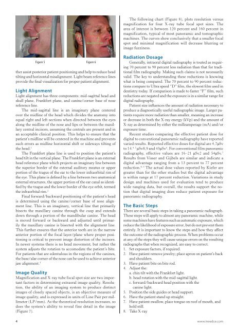
Figure 5 Figure 6<br />
ther assist posterior patient positioning and help to reduce head<br />
tilting and horizontal misalignment. Light beam reference lines<br />
provide the final visualization for proper patient alignment.<br />
Light Alignment<br />
Light alignment has three <strong>com</strong>ponents: mid-sagittal head and<br />
skull plane, Frankfort plane, and canine/corner base of nose<br />
reference line.<br />
The mid-sagittal line is an imaginary plane centered<br />
over the midline of the head which divides the anatomy into<br />
equal right and left sections when directed between the eyes<br />
along the midline of the nose and lips or between the maxillary<br />
central incisors, assuming the centrals are present and in<br />
an acceptable clinical position. This helps to ensure that the<br />
patient’s midline will be centered in the machine and prevents<br />
such errors as midline horizontal shift or sideways tilting of<br />
the head. 1<br />
The Frankfort plane line is used to position the patient’s<br />
head tilt in the vertical plane. The Frankfort plane is an external<br />
head reference plane which projects an imaginary line between<br />
the superior border of the external auditory meatus or upper<br />
portion of the tragus of the ear to the lower infraorbital rim of<br />
the eye. This plane is defined by a line between two anatomical<br />
external structures, the upper portion of the ear canal as identified<br />
by the tragus and the lower border of the eye orbit, termed<br />
the infraorbital rim. 2<br />
Final forward/backward positioning of the patient’s head<br />
is determined using the canine/corner base of nose alignment<br />
line. This is an imaginary, vertical line that primarily<br />
bisects the maxillary canine through the cusp and extends<br />
down through a portion of the mandibular canine. The head<br />
is moved forward or backward and adjusted until primarily<br />
the maxillary canine is bisected with the alignment line.<br />
This further ensures that the anterior teeth are in the narrow<br />
anterior portion of the focal layer/plane where proper positioning<br />
is critical to prevent image distortion of the incisors.<br />
In newer systems there is no head movement, but rather the<br />
system adjusts the rotation to ac<strong>com</strong>odate the patient’s bite.<br />
For patients that are edentulous in the regions of the canines,<br />
the base/alar corner of the nose can be used to achieve anterior<br />
jaw alignment. 3<br />
Image Quality<br />
Magnification and X-ray tube focal spot size are two important<br />
factors in determining extraoral image quality. Resolution,<br />
the ability of an imaging system to produce distinct<br />
images of closely spaced objects, is an objective measure of<br />
image quality, and is expressed in units of Line Pair per millimeter<br />
(LP/mm). As the theoretical resolution increases, so<br />
does the system’s ability to reveal fine detail in the image<br />
(Figure 7).<br />
Radiation Dosage<br />
Generally, intraoral digital radiography is touted as requiring<br />
70 percent to 90 percent less radiation than that for traditional<br />
film radiography. Making such claims is not necessarily<br />
valid. The key to understanding these reductions is knowing<br />
what is being <strong>com</strong>pared. The 70 percent to 90 percent reductions<br />
<strong>com</strong>pare to Ultra speed “D” film, the slowest film used in<br />
dentistry today. If <strong>com</strong>parison is made to faster “F” film, such<br />
reductions are negated and the exposure is in a similar range for<br />
digital radiography.<br />
Patient size influences the amount of radiation necessary to<br />
produce a diagnostically useful radiographic image. Larger patients<br />
require more radiation than smaller, meaning an increase<br />
or decrease in both the X-ray energy (kVp) and the amount of<br />
X-ray as determined by either the milleamperage (mA) and/or<br />
exposure time.<br />
Recent studies <strong>com</strong>paring the effective patient dose for<br />
digital to conventional panoramic radiography have reported<br />
varied results. Reported effective doses for digital are 4.7µSv<br />
to 14. 4, 5 µSv8,9 and 45µSv 6 . For conventional film panoramic<br />
radiography, effective values are 16–21 µSv2 and 54µSv. 7<br />
Results from Visser and Gijbels are similar and indicate a<br />
digital advantage ranging from a 13 percent to 77 percent<br />
reduction. 8, 9 The actual dose values reported by Kiefer are<br />
greater than for the other studies but the digital advantage<br />
is within range at 17 percent reduction. Variations in study<br />
design and machines used for evaluation tend to produce<br />
wide ranging data, but overall, the results support the notion<br />
that digital imaging does reduce patient exposure for<br />
panoramic radiography.<br />
The Basic Steps<br />
There are several basic steps in taking a panoramic radiograph.<br />
These steps will apply to almost any panoramic machine, while<br />
some machines have features such as automatic exposure, which<br />
reduce the likelihood of exposure error, but do not prevent them<br />
entirely. It is important to know the steps and how they affect<br />
the out<strong>com</strong>e of the radiographic process. When problems occur<br />
at any of the steps they will cause unique errors on the resulting<br />
radiographs that when recognized, are easy to correct.<br />
1. Set exposure factors, if required.<br />
2. Have patient remove jewelry; place apron on patient’s back<br />
and shoulders.<br />
3. Have patient bite on bite rod.<br />
4. Adjust the:<br />
a. chin tilt with the Frankfort light.<br />
b. head rotation with the mid-sagittal light.<br />
c. forward/backward head position with the<br />
canine light.<br />
5. Position the side guides or head support.<br />
6. Have the patient stand up straight.<br />
7. Have patient swallow, place tongue on roof of mouth, and<br />
hold still.<br />
8. Take X-ray<br />
4 www.ineedce.<strong>com</strong>