TCA 785 Phase Control IC TCA 785 - Infineon
TCA 785 Phase Control IC TCA 785 - Infineon
TCA 785 Phase Control IC TCA 785 - Infineon

You also want an ePaper? Increase the reach of your titles
YUMPU automatically turns print PDFs into web optimized ePapers that Google loves.
<strong>TCA</strong> <strong>785</strong><br />
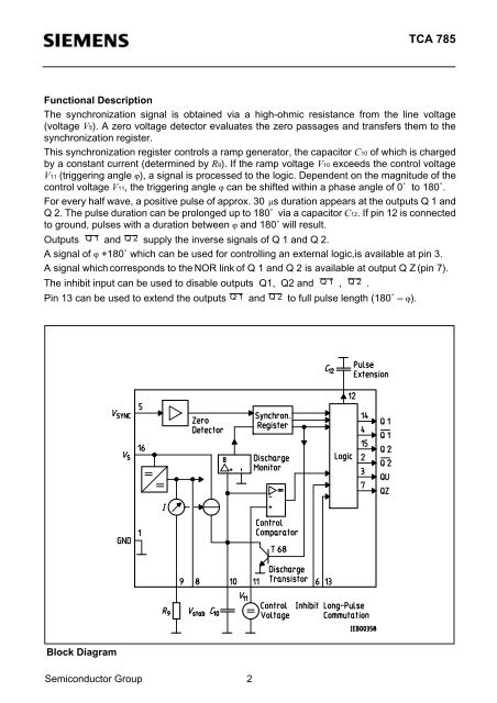
Functional Description<br />
The synchronization signal is obtained via a high-ohmic resistance from the line voltage<br />
(voltage V5). A zero voltage detector evaluates the zero passages and transfers them to the<br />
synchronization register.<br />
This synchronization register controls a ramp generator, the capacitor C10 of which is charged<br />
by a constant current (determined by R9). If the ramp voltage V10 exceeds the control voltage<br />
V11 (triggering angle ϕ), a signal is processed to the logic. Dependent on the magnitude of the<br />
control voltage V11, the triggering angle ϕ can be shifted within a phase angle of 0˚ to 180˚.<br />
For every half wave, a positive pulse of approx. 30 µs duration appears at the outputs Q 1 and<br />
Q 2. The pulse duration can be prolonged up to 180˚ via a capacitor C12. If pin 12 is connected<br />
to ground, pulses with a duration between ϕ and 180˚ will result.<br />
Outputs Q 1 and Q 2 supply the inverse signals of Q 1 and Q 2.<br />
A signal of ϕ +180˚ which can be used for controlling an external logic,is available at pin 3.<br />
A signal which corresponds to the NOR link of Q 1 and Q 2 is available at output Q Z (pin 7).<br />
The inhibit input can be used to disable outputs Q1, Q2 and Q 1 , Q 2 .<br />
Pin 13 can be used to extend the outputs Q 1 and Q 2 to full pulse length (180˚ – ϕ).<br />
Block Diagram<br />
Semiconductor Group 2