

Manifolds in composite specifically designed for radiant ... - Caleffi
Manifolds in composite specifically designed for radiant ... - Caleffi
Manifolds in composite specifically designed for radiant ... - Caleffi

Create successful ePaper yourself
Turn your PDF publications into a flip-book with our unique Google optimized e-Paper software.
<strong>Manifolds</strong> <strong>in</strong> <strong>composite</strong> <strong>specifically</strong><br />
<strong>designed</strong> <strong>for</strong> <strong>radiant</strong> panel systems<br />
670 series<br />
Product range<br />
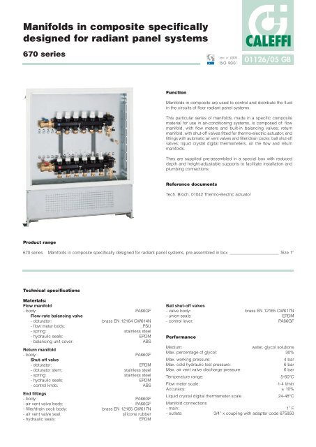
Function<br />
cert. n° 0003<br />
ISO 9001<br />
01126/05 GB<br />
<strong>Manifolds</strong> <strong>in</strong> <strong>composite</strong> are used to control and distribute the fluid<br />
<strong>in</strong> the circuits of floor <strong>radiant</strong> panel systems.<br />
This particular series of manifolds, made <strong>in</strong> a specific <strong>composite</strong><br />
material <strong>for</strong> use <strong>in</strong> air-condition<strong>in</strong>g systems, is composed of: flow<br />
manifold, with flow meters and built-<strong>in</strong> balanc<strong>in</strong>g valves; return<br />
manifold, with shut-off valves fitted <strong>for</strong> thermo-electric actuator; end<br />
fitt<strong>in</strong>gs with automatic air vent valves and filler/dra<strong>in</strong> cocks; ball shut-off<br />
valves; liquid crystal digital thermometers, on the flow and return<br />
manifolds.<br />
They are supplied pre-assembled <strong>in</strong> a special box with reduced<br />
depth and height-adjustable supports to facilitate <strong>in</strong>stallation and<br />
plumb<strong>in</strong>g connections.<br />
Reference documents<br />
Tech. Broch. 01042 Thermo-electric actuator<br />
CALEFFI<br />
670 series <strong>Manifolds</strong> <strong>in</strong> <strong>composite</strong> <strong>specifically</strong> <strong>designed</strong> <strong>for</strong> <strong>radiant</strong> panel systems, pre-assembled <strong>in</strong> box Size 1”<br />
Technical specifications<br />
Materials:<br />
Flow manifold<br />
- body: PA66GF<br />
Flow-rate balanc<strong>in</strong>g valve<br />
- obturator: brass EN 12164 CW614N<br />
- flow meter body: PSU<br />
- spr<strong>in</strong>g: sta<strong>in</strong>less steel<br />
- hydraulic seals: EPDM<br />
- balanc<strong>in</strong>g unit cover: ABS<br />
Return manifold<br />
- body: PA66GF<br />
Shut-off valve<br />
- obturator: EPDM<br />
- obturator stem: sta<strong>in</strong>less steel<br />
- spr<strong>in</strong>g: sta<strong>in</strong>less steel<br />
- hydraulic seals: EPDM<br />
- control knob: ABS<br />
End fitt<strong>in</strong>gs<br />
- body: PA66GF<br />
- air vent valve body: PA66GF<br />
- filler/dra<strong>in</strong> cock body: brass EN 12165 CW617N<br />
- air vent valve seal: silicone rubber<br />
- hydraulic seals: EPDM<br />
Ball shut-off valves<br />
- valve body: brass EN 12165 CW617N<br />
- union seals: EPDM<br />
- control lever: PA66GF<br />
Per<strong>for</strong>mance<br />
Medium: water, glycol solutions<br />
Max. percentage of glycol: 30%<br />
Max. work<strong>in</strong>g pressure: 4 bar<br />
Max. cold hydraulic test pressure: 6 bar<br />
Max. air vent valve discharge pressure: 6 bar<br />
Temperature range: 5-60°C<br />
Flow meter scale: 1-4 l/m<strong>in</strong><br />
Accuracy: ± 10%<br />
Liquid crystal digital thermometer scale<br />
Manifold connections<br />
24-48°C<br />
- ma<strong>in</strong>: 1” F<br />
- outlets: 3/4” x coupl<strong>in</strong>g with adapter code 675850
Code<br />
Nr. outlets<br />
A<br />
B (Wall box width)<br />
Weight (kg)<br />
6706C1<br />
3<br />
300<br />
600<br />
14,8<br />
6706D1<br />
4<br />
350<br />
600<br />
15,0<br />
6706E1<br />
5<br />
400<br />
600<br />
15,2<br />
6706F1<br />
6<br />
450<br />
600<br />
15,4<br />
6706G1<br />
7<br />
500<br />
800<br />
19,4<br />
6706H1<br />
8<br />
550<br />
800<br />
19,6<br />
6706I1<br />
9<br />
600<br />
800<br />
19,8<br />
6706L1<br />
10<br />
650<br />
800<br />
20,0<br />
550<br />
A<br />
50<br />
270-410<br />
110<br />
1<br />
2<br />
3<br />
4<br />
L/MIN<br />
1<br />
2<br />
3<br />
4<br />
L/MIN<br />
1<br />
2<br />
3<br />
4<br />
L/MIN<br />
1<br />
2<br />
3<br />
4<br />
L/MIN<br />
1<br />
2<br />
3<br />
4<br />
L/MIN<br />
1<br />
2<br />
3<br />
4<br />
L/MIN<br />
B<br />
30<br />
48<br />
BAGNO<br />
ENTRATA<br />
PRANZO<br />
CUCINA<br />
CAMERA<br />
C. MATRIM.<br />
BAGNO<br />
ENTRATA<br />
PRANZO<br />
CUCINA<br />
CAMERA<br />
C. MATRIM.<br />
°C<br />
°C<br />
80-120<br />
255 195<br />
43<br />
1”<br />
1”<br />
91<br />
65 70<br />
6°<br />
Dimensions
Characteristic components<br />
12<br />
2<br />
4<br />
9<br />
11<br />
1<br />
CAMERA<br />
1<br />
2<br />
3<br />
4<br />
L/MIN<br />
CAMERA<br />
C. MATRIM.<br />
1<br />
2<br />
3<br />
4<br />
L/MIN<br />
C. MATRIM.<br />
°C<br />
PRANZO<br />
1<br />
2<br />
3<br />
4<br />
L/MIN<br />
°C<br />
PRANZO<br />
ENTRATA<br />
10 5 6<br />
Pre-assembled unit complete with:<br />
1) Flow manifold with flow meters and built-<strong>in</strong> flow rate balanc<strong>in</strong>g valves<br />
2) Return manifold with built-<strong>in</strong> shut-off valves fitted <strong>for</strong> thermo-electric actuator<br />
3) End fitt<strong>in</strong>gs with automatic air vent with hygroscopic cap, discharge valve and filler/dra<strong>in</strong> cock<br />
4) Pair of ball shut-off valves<br />
5) Liquid crystal digital thermometers on the flow and return manifolds<br />
6) Adhesive labels <strong>in</strong>dicat<strong>in</strong>g the rooms<br />
7) Pair of brackets fasten<strong>in</strong>g to the box<br />
8) Box with adjustable height and depth<br />
9) Coupl<strong>in</strong>g adapter with clip 675850 code<br />
10) Template <strong>for</strong> cutt<strong>in</strong>g pipe 675002 code<br />
Accessories<br />
11) 680 series s<strong>in</strong>gle and multi-layer plastic pipe fitt<strong>in</strong>g with self-adjustable diameter<br />
12) 656 series thermo-electric actuator<br />
13) Push-fit thermometer <strong>for</strong> panel circuit 675900 code<br />
1<br />
2<br />
3<br />
4<br />
L/MIN<br />
ENTRATA<br />
CUCINA<br />
1<br />
2<br />
3<br />
4<br />
L/MIN<br />
CUCINA<br />
BAGNO<br />
°C<br />
50 50<br />
40 40<br />
30 30<br />
20 20<br />
10 10<br />
1<br />
2<br />
3<br />
4<br />
L/MIN<br />
BAGNO<br />
8<br />
3<br />
7<br />
13
Construction details<br />
Specific plastic material<br />
The manifolds are made with a <strong>specifically</strong> selected polymer <strong>for</strong> heat<strong>in</strong>g and cool<strong>in</strong>g system applications. The basic characteristics <strong>for</strong> this use are:<br />
- high stra<strong>in</strong> resistance while ma<strong>in</strong>ta<strong>in</strong><strong>in</strong>g good ultimate elongation<br />
- good resistance to crack propagation<br />
- very low moisture absorption, <strong>for</strong> constant mechanical behaviour<br />
- high abrasion resistance due to medium constant flow<br />
- per<strong>for</strong>mance stability to temperature changes<br />
- compatibility with the glycols and additives used <strong>in</strong> the circuits<br />
These basic material characteristics, comb<strong>in</strong>ed with the appropriate shap<strong>in</strong>g of the most highly stressed areas, enable a comparison with the<br />
metals typically used <strong>in</strong> the construction of distribution manifolds.<br />
Return manifold<br />
The return manifold is equipped with built-<strong>in</strong> shut-off valves. Us<strong>in</strong>g<br />
the shut-off valve with a manual knob, the flow rate to the s<strong>in</strong>gle<br />
circuits can be reduced so much as to shut off the circuit<br />
completely. The valve is equipped with a sta<strong>in</strong>less steel control<br />
stem <strong>in</strong> a s<strong>in</strong>gle piece, with a double O-r<strong>in</strong>g seal. The rubber<br />
obturator is specially shaped to m<strong>in</strong>imize the losses of head and<br />
the noise produced by the flow of the medium, prevent<strong>in</strong>g the seal<br />
seat from possibly stick<strong>in</strong>g.<br />
The valves are fitted to accommodate thermo-electric actuator <strong>in</strong> order<br />
to automate their action upon receiv<strong>in</strong>g a signal from an ambient<br />
thermostat.<br />
Flow manifold<br />
The flow manifold is equipped with flow meters and built-<strong>in</strong> flow rate<br />
balanc<strong>in</strong>g valves.<br />
Us<strong>in</strong>g the balanc<strong>in</strong>g valve with the special tapered obturator, the<br />
flow rate to the s<strong>in</strong>gle circuits can be adjusted accurately as<br />
required, with the sett<strong>in</strong>g be<strong>in</strong>g read off the s<strong>in</strong>gle flow meter with a<br />
scale of 1-4 l/m<strong>in</strong>. This simplifies and speeds up the operation of<br />
calibrat<strong>in</strong>g the circuit, with no need <strong>for</strong> reference graphs. After<br />
balanc<strong>in</strong>g, the valve can be locked <strong>in</strong> position by means of its<br />
tamper-proof cover.<br />
This valve makes it possible to seal off the s<strong>in</strong>gle circuit should this<br />
be necessary.
Modular manifolds<br />
The manifolds and end fitt<strong>in</strong>gs<br />
are modular thanks to the<br />
threaded connections with<br />
O-r<strong>in</strong>g seals and lock clips<br />
prevent<strong>in</strong>g unscrew<strong>in</strong>g. With<br />
this connection system, the<br />
operation of assembl<strong>in</strong>g the<br />
various components is simplified<br />
and the hydraulic seal is fully<br />
assured.<br />
End fitt<strong>in</strong>g<br />
The end fitt<strong>in</strong>g is equipped with an automatic air vent with hygroscopic<br />
safety cap, discharge valve and filler/dra<strong>in</strong> ball cock.<br />
The automatic air vent is equipped with a removal mechanism air with<br />
a silicone rubber obturator. The vent mechanism is connected to the<br />
valve body by a fix<strong>in</strong>g clip, mak<strong>in</strong>g any <strong>in</strong>spection and ma<strong>in</strong>tenance<br />
work easier.<br />
The hygroscopic safety plug anyhow prevents water leak<strong>in</strong>g to<br />
protect the <strong>in</strong>stallation. The manual discharge valve speeds up the<br />
operation of fill<strong>in</strong>g the circuit, done by us<strong>in</strong>g the dra<strong>in</strong>/filler ball cock.<br />
Digital thermometers<br />
A liquid crystal digital thermometer is fitted on the flow and return<br />
manifold body, on both sides, with a temperature range of 24-48°C.<br />
The liquid crystals automatically light up green at the measured<br />
temperature, mak<strong>in</strong>g it easy to read even when there is poor light<strong>in</strong>g.<br />
This thermometer is calibrated to display the actual temperature of<br />
the medium, which is essential to evaluate the system’s thermal<br />
load and operat<strong>in</strong>g conditions.<br />
Replaceable components<br />
The headworks of the balanc<strong>in</strong>g valve with flow meter and of the<br />
shut-off valve can be removed and replaced with spare parts.<br />
Panel circuit outlets<br />
The outlet connections of the s<strong>in</strong>gle panel circuits are <strong>designed</strong> to<br />
use a special coupl<strong>in</strong>g adapter that can be removed with a fix<strong>in</strong>g<br />
clip. The brass adapter has a double O-r<strong>in</strong>g seal and a hexagon on<br />
its surface. The pipe fitt<strong>in</strong>g is<br />
connected straight onto the<br />
threaded side. With this<br />
particular connection system,<br />
the fitt<strong>in</strong>g with the adapter can<br />
be tightened onto the pip<strong>in</strong>g<br />
outside the box and then<br />
coupled on the manifold body<br />
later, mak<strong>in</strong>g the plumb<strong>in</strong>g<br />
<strong>in</strong>stallation simpler and more<br />
practical.<br />
Room identification<br />
On the manifold body, at the outlet of<br />
each panel circuit, there is a special<br />
surface <strong>for</strong> affix<strong>in</strong>g an adhesive label<br />
identify<strong>in</strong>g the correspond<strong>in</strong>g room.
Thermometers <strong>for</strong> loop pip<strong>in</strong>g<br />
As an accessory, a special spirit<br />
thermometer with a scale of<br />
5-50°C is available, equipped<br />
with a push-fit plastic body, <strong>for</strong><br />
the s<strong>in</strong>gle loop pip<strong>in</strong>g, with an<br />
outside diameter from 15 to 18 mm.<br />
This thermometer, <strong>in</strong>stalled on<br />
the return l<strong>in</strong>e, measures the<br />
actual temperature of the<br />
medium return<strong>in</strong>g from the<br />
circuit mak<strong>in</strong>g it possible to<br />
check the state of the s<strong>in</strong>gle<br />
panel’s heat transfer accurately.<br />
Bracket<strong>in</strong>g<br />
The manifolds have holes to<br />
secure them on brackets to allow<br />
hous<strong>in</strong>g them <strong>in</strong> boxes.<br />
The manifolds are reversible, <strong>in</strong><br />
that they can be positioned with<br />
the entry from the right or left.<br />
The return manifold, located at<br />
the top, is <strong>in</strong>stalled at an angle<br />
on purpose <strong>in</strong> order to make it<br />
easier <strong>for</strong> the panel circuit pipes<br />
to pass through, up to 20 mm <strong>in</strong><br />
diameter.<br />
The manifolds can thus be<br />
bracketed <strong>in</strong> a box just 80 mm<br />
deep, allow<strong>in</strong>g <strong>for</strong> <strong>in</strong>stallation <strong>in</strong><br />
th<strong>in</strong> walls.<br />
Shut-off valves<br />
The ball shut-off valves on the<br />
flow and return of the circuits are<br />
the union-type with a flat-seat<br />
seal made of EPDM.<br />
Box<br />
The manifolds are supplied bracketed <strong>in</strong> a recess-mount<strong>in</strong>g plate<br />
box with an adjustable depth from 80 to 120 mm. The box,<br />
<strong>specifically</strong> <strong>designed</strong> to be used with <strong>radiant</strong> panel systems, is<br />
equipped with floor supports that are adjustable <strong>in</strong> height from<br />
270 to 410 mm, the height be<strong>in</strong>g chosen accord<strong>in</strong>g to the thickness<br />
of the slab. With these supports, the pipe passageway is clear of<br />
obstruction; a double curta<strong>in</strong> wall then enables the plaster<strong>in</strong>g to be<br />
done directly and the correct fitt<strong>in</strong>g of frame and cover. The back wall<br />
of the box has grooves and holes to secure the manifold brackets;<br />
the side and top walls have holes <strong>for</strong> the ma<strong>in</strong> pipes to pass through.<br />
The cover is opened and closed us<strong>in</strong>g a special handle with a<br />
push-fit clamp, without us<strong>in</strong>g any keys or tools.<br />
The box is also customizable <strong>for</strong> connect<strong>in</strong>g the ma<strong>in</strong> pipes com<strong>in</strong>g<br />
<strong>in</strong> from the top.
Hydraulic characteristics<br />
In order to determ<strong>in</strong>e the hydraulic characteristics of the circuit, it is necessary to calculate the total loss of head suffered by the flow of medium<br />
on pass<strong>in</strong>g through the devices <strong>for</strong>m<strong>in</strong>g the manifold assembly and the <strong>radiant</strong> panel circuits.<br />
From a hydraulic po<strong>in</strong>t of view, the system composed of the manifold assembly and the circuits can be represented as a set of hydraulic elements<br />
arranged <strong>in</strong> series and <strong>in</strong> parallel.<br />
G Tot.<br />
∆P Tot.<br />
∆P Ball V<br />
G Tot.<br />
∆P F. Man.<br />
∆P Ball V<br />
∆P Ball V<br />
∆P BV<br />
∆P Loop<br />
∆P Tot.<br />
∆P Loop<br />
CAMERA<br />
1<br />
2<br />
3<br />
4<br />
L/MIN<br />
CAMERA<br />
C. MATRIM.<br />
1<br />
2<br />
3<br />
4<br />
L/MIN<br />
C. MATRIM.<br />
∆P SV<br />
G Loop<br />
∆P R Man.<br />
∆PTot. = ∆PBV +∆PLoop + ∆PSV + ∆PF Man. + ∆PR Man. + ∆PBall V x 2<br />
°C<br />
PRANZO<br />
1<br />
2<br />
3<br />
4<br />
L/MIN<br />
°C<br />
PRANZO<br />
ENTRATA<br />
1<br />
2<br />
3<br />
4<br />
L/MIN<br />
ENTRATA<br />
∆P F Man.<br />
∆P R Man.<br />
∆PTot. = Total loss at the ends of the manifold<br />
(Flow + Return + Loop)<br />
∆PBV = Localized loss at loop balanc<strong>in</strong>g valve<br />
(loop flow rate)<br />
∆PLoop = Loop loss (loop flow rate)<br />
∆PSV = Localized loss at panel circuit<br />
shut-off valve (loop flow rate)<br />
∆PF. Man. = Distributed loss of the flow manifold<br />
(total flow rate)<br />
∆PR. Man. = Distributed loss of the return manifold<br />
(total flow rate)<br />
∆PBall V. = Ball valve loss (total flow rate)<br />
When the hydraulic characteristics of each component and the design flow rates are known, the total loss can be calculated as the sum of the<br />
partial losses of head <strong>for</strong> each specific component of the system, as <strong>in</strong>dicated with the <strong>for</strong>mula (1.1).<br />
∆P SV<br />
CUCINA<br />
1<br />
2<br />
3<br />
4<br />
L/MIN<br />
CUCINA<br />
BAGNO<br />
∆P BV<br />
1<br />
2<br />
3<br />
4<br />
L/MIN<br />
BAGNO<br />
∆P Ball V<br />
G Tot.<br />
G Loop<br />
(1.1)
Hydraulic characteristics<br />
∆P (mm w.g.)<br />
1000<br />
500<br />
200<br />
100<br />
900<br />
800<br />
700<br />
600<br />
450<br />
400<br />
350<br />
300<br />
180<br />
160<br />
140<br />
120<br />
90<br />
80<br />
70<br />
60<br />
50<br />
250<br />
45<br />
40<br />
35<br />
30<br />
20<br />
10<br />
25<br />
18<br />
16<br />
14<br />
12<br />
20<br />
25<br />
30<br />
Example of calculation of total loss of head<br />
Suppos<strong>in</strong>g we need to calculate the loss of head of a manifold with three outlets with the follow<strong>in</strong>g characteristics:<br />
Total manifold flow rate: 350 l/h<br />
The pipes of the three loops have the follow<strong>in</strong>g characteristics of flow rate and loss of head:<br />
Circuit 1 Circuit 2 Circuit 3<br />
∆P1 = 10 kPa ∆P2 = 15 kPa ∆P3 = 7 kPa (1.2)<br />
G1 = 120 l/h G2 = 150 l/h G3 = 80 l/h<br />
We calculate each term of the <strong>for</strong>mula (1.1), us<strong>in</strong>g the relationship:<br />
∆P = G 2 /Kv 0.01 2<br />
35<br />
40<br />
45<br />
50<br />
60<br />
70<br />
80<br />
90<br />
· G = flow rate <strong>in</strong> l/h<br />
· ∆P = loss of head <strong>in</strong> kPa (1 kPa =100 mm w.g.)<br />
· Kv 0,01 = flow rate <strong>in</strong> l/h through the device, which corresponds to a head loss of 1 kPa<br />
It should be stressed that the calculation of ∆PTot. must be made tak<strong>in</strong>g account of the circuit <strong>in</strong> which there are the greatest head losses<br />
distributed along the entire loop of the panel pip<strong>in</strong>g.<br />
In the case we are exam<strong>in</strong><strong>in</strong>g, the relevant circuit is No. 2.<br />
It follows that:<br />
∆PBV = 1502 /1002 = 2,25 kPa<br />
∆PLoop = 15 kPa<br />
∆PSV = 1502 /2402 = 0,39 kPa<br />
∆PF Man. = 3502 /16002 = 0,05 kPa } Values obta<strong>in</strong>ed by disregard<strong>in</strong>g variations due to flow rate to each branch circuit<br />
∆PR Man. = 3502 /16002 = 0,05 kPa<br />
∆PBall V = 3502 /16502 = 0,04 kPa<br />
By means of (1.1) add<strong>in</strong>g up all the calculated terms, we have:<br />
∆PTot.= 2,25 + 15 + 0,39 + 0,05 + 0,05 + 0,04 = 17,64 kPa<br />
100<br />
Flow rate balanc<strong>in</strong>g valve fully open<br />
Shut-off valve<br />
120<br />
140<br />
160<br />
180<br />
- Kv = flow rate <strong>in</strong> m 3 /h <strong>for</strong> a loss of head of 1 bar<br />
- Kv 0,01 = flow rate <strong>in</strong> l/h <strong>for</strong> a loss of head of 1 kPa<br />
200<br />
250<br />
300<br />
350<br />
400<br />
450<br />
Kv<br />
1,00<br />
2,40<br />
500<br />
G (l/h)<br />
∆P (kPa)<br />
Note:<br />
Because of the low head losses <strong>for</strong> the ball valves and the manifolds, the three terms relat<strong>in</strong>g to them can be neglected.<br />
In general, the total head loss is reasonably approximate to that of the branched circuit of the panel.<br />
9<br />
8<br />
7<br />
6<br />
2,5<br />
10<br />
5<br />
4,5<br />
4<br />
3,5<br />
3<br />
2<br />
1,8<br />
1,6<br />
1,4<br />
1,2<br />
1<br />
0,9<br />
0,8<br />
0,7<br />
0,6<br />
0,25<br />
0,5<br />
0,45<br />
0,4<br />
0,35<br />
0,3<br />
0,2<br />
0,18<br />
0,16<br />
0,14<br />
0,12<br />
0,1<br />
Kv 0,01<br />
100<br />
240<br />
∆P (mm w.g.)<br />
1000<br />
500<br />
200<br />
100<br />
900<br />
800<br />
700<br />
600<br />
450<br />
400<br />
350<br />
300<br />
180<br />
160<br />
140<br />
120<br />
90<br />
80<br />
70<br />
60<br />
50<br />
20<br />
10<br />
250<br />
45<br />
40<br />
35<br />
30<br />
25<br />
18<br />
16<br />
14<br />
12<br />
500<br />
600<br />
Flow or return manifold 3÷6 outlets<br />
Flow or return manifold 7÷10 outlets<br />
Ball valve<br />
* Average value<br />
700<br />
800<br />
900<br />
1000<br />
1200<br />
1400<br />
1600<br />
1800<br />
2000<br />
2500<br />
3000<br />
Kv<br />
16,0*<br />
12,0*<br />
16,5*<br />
3500<br />
G (l/h)<br />
∆P (kPa)<br />
4000<br />
9<br />
8<br />
7<br />
6<br />
2,5<br />
10<br />
5<br />
4,5<br />
4<br />
3,5<br />
3<br />
2<br />
1,8<br />
1,6<br />
1,4<br />
1,2<br />
1<br />
0,9<br />
0,8<br />
0,7<br />
0,6<br />
0,25<br />
0,5<br />
0,45<br />
0,4<br />
0,35<br />
0,3<br />
0,2<br />
0,18<br />
0,16<br />
0,14<br />
0,12<br />
0,1<br />
Kv0,01 1600*<br />
1200*<br />
1650*
Us<strong>in</strong>g balanc<strong>in</strong>g valves with flow meter<br />
The balanc<strong>in</strong>g valves <strong>in</strong> the flow manifold make it possible to balance each s<strong>in</strong>gle circuit of the panels to obta<strong>in</strong> the actual design flow rates.<br />
Consider<strong>in</strong>g the follow<strong>in</strong>g data:<br />
- flow rate of medium that must flow through each circuit<br />
- head loss that <strong>for</strong> this flow rate is generated <strong>in</strong> each circuit:<br />
∆PCircuit = ∆PLoop + ∆PSV (∆PShut-off valve)<br />
- available head on the panel circuit or predeterm<strong>in</strong>ed head:<br />
HPredeterm<strong>in</strong>ed ≥ ∆PCircuit + = ∆PBV + ∆PLoop + ∆PSV<br />
disadvantaged<br />
Referr<strong>in</strong>g to the diagram alongside, the balanc<strong>in</strong>g valve must, <strong>for</strong> the<br />
loop flow rate, provide an additional head loss equal to the difference<br />
∆PBV (∆PBalanc<strong>in</strong>g valve).<br />
Flow rate adjustment and read<strong>in</strong>g<br />
HPredeterm<strong>in</strong>ed ≥ ∆PCircuit +<br />
disadvantaged<br />
Raise the block cover with the aid of a screwdriver and turn it over onto the flow meter. Adjust the flow rate of the s<strong>in</strong>gle panels by turn<strong>in</strong>g the<br />
flow meter body that acts on the built-<strong>in</strong> balanc<strong>in</strong>g valve.<br />
The flow rate must be read off the graduated scale, expressed <strong>in</strong> l/m<strong>in</strong>, pr<strong>in</strong>ted on the flow meter.<br />
After mak<strong>in</strong>g all the adjustments, reposition all the knobs and hook them <strong>in</strong> their seat to prevent tamper<strong>in</strong>g.<br />
∆P Tot.<br />
SPECIFICATION SUMMARIES<br />
SV<br />
BV<br />
∆PCircuit<br />
670 series<br />
Manifold <strong>in</strong> <strong>composite</strong> <strong>specifically</strong> <strong>designed</strong> <strong>for</strong> <strong>radiant</strong> panel systems with 3 (from 3 to 10) outlets. Body of PA66GF. Seals<br />
of EPDM. Head connections: 1” F threaded. Outlet connections: 3/4” M. Media: water and glycol solutions. Maximum<br />
percentage of glycol 30%. Maximum work<strong>in</strong>g pressure 4 bar. Temperature range 5-60°C. Maximum automatic air vent<br />
discharge pressure 6 bar.<br />
Complete with:<br />
- Flow manifold with flow-rate balanc<strong>in</strong>g valves and flow meter with graduated scale 1-4 l/m<strong>in</strong>.<br />
Accuracy ± 10%.<br />
- Return manifold with shut-off valves fitted <strong>for</strong> thermo-electric actuator.<br />
- Pair of end fitt<strong>in</strong>gs with automatic air vent with hygroscopic cap, discharge valve, filler/dra<strong>in</strong> cock.<br />
- Pair of ball shut-off valves, brass body. Union seals made of EPDM.<br />
- Liquid crystal digital thermometers on the flow and return manifolds. Scale 24-48°C.<br />
- Adhesive labels <strong>in</strong>dicat<strong>in</strong>g the rooms.<br />
- Pair of fix<strong>in</strong>g brackets.<br />
- Box made of pa<strong>in</strong>ted sheet steel with clamp; adjustable depth of from 80 to 120 mm; with floor supports that are<br />
adjustable from 270 to 410 mm.<br />
- Coupl<strong>in</strong>g adapter with clip 675850 code <strong>for</strong> manifold outlet and pipe fitt<strong>in</strong>g connection 680 series.<br />
- Template <strong>for</strong> pipe cutt<strong>in</strong>g 675002 code.<br />
∆P BV
Accessories<br />
675<br />
Coupl<strong>in</strong>g adapter with clip code 675850 <strong>for</strong> manifold outlet 670 series<br />
and pipe fitt<strong>in</strong>g connection 680 series.<br />
Size: 3/4” M - Ø 18-clip coupl<strong>in</strong>g.<br />
Technical and construction specifications<br />
Materials: - body: brass EN 12164 CW614N<br />
- seal: double O-r<strong>in</strong>g of EPDM<br />
- clip: sta<strong>in</strong>less steel<br />
Medium: water, glycol solutions<br />
Max. percentage of glycol: 30%<br />
Max. work<strong>in</strong>g pressure: 10 bar<br />
Temperature range: 0-100°C<br />
5-60°C (coupled <strong>in</strong> the manifold 670)<br />
Connection: 3/4” M - Ø 18-clip coupl<strong>in</strong>g<br />
680<br />
S<strong>in</strong>gle and multi-layer plastic pipe fitt<strong>in</strong>g with self-adjustable diameter.<br />
Size 3/4”.<br />
Technical and construction specifications<br />
Materials: - adapter: brass EN 12164 CW614N<br />
- nut: brass EN 12164 CW614N<br />
- pipe clench<strong>in</strong>g r<strong>in</strong>g: PA66GF<br />
- seals: EPDM<br />
- dielectric seal r<strong>in</strong>g: EPDM<br />
Medium: water, glycol solutions<br />
Max percentage of glycol: 30%<br />
Max work<strong>in</strong>g pressure: 10 bar<br />
Temperature range: 5-80°C (PEX)<br />
5-50°C (Multi-layer)<br />
Connection: 3/4”<br />
Construction details<br />
Pipe-fitt<strong>in</strong>g coupl<strong>in</strong>g flexibility<br />
This fitt<strong>in</strong>g has been <strong>specifically</strong> <strong>designed</strong> <strong>in</strong> order to adjust to several pipe diameters. The great<br />
variety of plastic pipes, s<strong>in</strong>gle and multi-layer, on the market and the breadth of permissible tolerances<br />
have made it necessary to design a specific fitt<strong>in</strong>g.<br />
Keep<strong>in</strong>g the nom<strong>in</strong>al dimensions of the fitt<strong>in</strong>gs currently on the market, the new construction<br />
solution makes it possible to use the same fitt<strong>in</strong>g <strong>for</strong> pipes with differences on their outside<br />
diameter of up to 2 mm and on their <strong>in</strong>side diameter of up to 0,5 mm.<br />
Pull-out resistance<br />
This fitt<strong>in</strong>g opposes high resistance to pipe pull-out. Its special tighten<strong>in</strong>g system makes it<br />
suitable <strong>for</strong> all applications, ensur<strong>in</strong>g a perfect hydraulic seal.<br />
Low head losses<br />
The <strong>in</strong>ternal profile of the adapter (1) is shaped to obta<strong>in</strong> a Venturi effect as the medium flows.<br />
It permits hav<strong>in</strong>g a head loss 20% lower than that correspond<strong>in</strong>g to passages of the same<br />
diameter.<br />
Dielectric seal r<strong>in</strong>g<br />
The fitt<strong>in</strong>g is equipped with a rubber <strong>in</strong>sulat<strong>in</strong>g element (2) to prevent contact between the<br />
alum<strong>in</strong>ium <strong>in</strong> the multi-layer pipe and the brass of the fitt<strong>in</strong>g. This prevents any galvanic<br />
corrosion generated by two different metals.<br />
Double O-r<strong>in</strong>g seal<br />
On the adapter there are two O-r<strong>in</strong>g seals (3) – (4) made of EPDM <strong>in</strong> order to avoid potential<br />
leaks even at high work<strong>in</strong>g pressures.<br />
1<br />
2<br />
3<br />
4<br />
Pip<strong>in</strong>g (mm)<br />
Code Ø<strong>in</strong>side Øoutside 680502<br />
680503<br />
680500<br />
680501<br />
680506<br />
680515<br />
680517<br />
680524<br />
680526<br />
680535<br />
680537<br />
680544<br />
680546<br />
680555<br />
680564<br />
680505<br />
3/4”<br />
3/4”<br />
3/4”<br />
3/4”<br />
3/4”<br />
3/4”<br />
3/4”<br />
3/4”<br />
3/4”<br />
3/4”<br />
3/4”<br />
3/4”<br />
3/4”<br />
3/4”<br />
3/4”<br />
3/4”<br />
7,5- 8<br />
8,5- 9<br />
9,5- 9,5<br />
1 9,5-10<br />
1 9,5-10<br />
10,5-11<br />
10,5-11<br />
11,5-12<br />
11,5-12<br />
12,5-13<br />
12,5-13<br />
13,5-14<br />
13,5-14<br />
14,5-15<br />
15,5-16<br />
17<br />
12-14<br />
12-14<br />
14-16<br />
12-14<br />
14-16<br />
14-16<br />
16-18<br />
14-16<br />
16-18<br />
16-18<br />
18-20<br />
16-18<br />
18-20<br />
18-20<br />
18-20<br />
22,50
Thermo-electric actuators<br />
6561 Tech. brosch. 01042<br />
Thermo-electric actuator.<br />
Normally closed.<br />
Code Voltage (V)<br />
656102<br />
656104<br />
Thermo-electric actuator.<br />
Normally closed.<br />
With auxiliary microswitch.<br />
Code<br />
656112<br />
656114<br />
675<br />
Push-fit thermometer <strong>for</strong> panel pip<strong>in</strong>g,<br />
code 675900.<br />
230<br />
224<br />
Voltage (V)<br />
230<br />
224<br />
Technical and constructional specifications<br />
Material: - body: PA6GF<br />
Thermometer fluid: alcohol<br />
Thermometer scale: 5-50°C<br />
Max. work<strong>in</strong>g temperature: 60°C<br />
Range of use of pipe outside (Øe) diam.:<br />
Conduct<strong>in</strong>g paste supplied <strong>in</strong> package<br />
from 15 to 18 mm<br />
SPECIFICATION SUMMARIES<br />
Technical and constructional specifications<br />
Materials: - protective shell self-ext<strong>in</strong>guish<strong>in</strong>g polycarbonate<br />
- colour<br />
Normally closed<br />
RAL 9010 white<br />
version with micro: RAL 9002 grey<br />
Electric supply: 230 V (ac) - 24 V (ac) - 24 V (dc)<br />
Start<strong>in</strong>g current: ≤ 1 A<br />
Work<strong>in</strong>g current: 230 V (ac) = 13 mA<br />
24 V (ac) - 24 V (dc) = 140 mA<br />
Power consumption: 3 W<br />
Auxiliary microswitch contacts rat<strong>in</strong>g (code 656112/114): 0,8 A (230 V)<br />
Protection class: IP 44 (<strong>in</strong> vertical position)<br />
Double <strong>in</strong>sulation construction: CE<br />
Max. ambient temperature: 50°C<br />
Operat<strong>in</strong>g time: open<strong>in</strong>g and clos<strong>in</strong>g from 120 s to 180 s<br />
Length of supply cable:<br />
Approval:<br />
80 cm<br />
695<br />
System test pump<br />
code 695000.<br />
Comprehensive of<br />
pressure gauge and<br />
hose <strong>for</strong> connect<strong>in</strong>g<br />
to the system.<br />
Technical and constructional specifications<br />
Materials: - body: bronze<br />
- piston: brass<br />
- control lever: galvanized steel<br />
Max. work<strong>in</strong>g pressure: 50 bar<br />
Water content: 12 l<br />
Pressure gauge scale: 0-60 bar<br />
Hose connection: 1/2”<br />
Hose length: 1,5 m<br />
680 series<br />
Self-adjustable diameter fitt<strong>in</strong>g <strong>for</strong> s<strong>in</strong>gle and multi-layer plastic pipes with <strong>in</strong>ternal profile hav<strong>in</strong>g a Venturi effect to limit head<br />
losses. Size 3/4” F. Nut and adapter made of brass, seals of EPDM, dielectric seal r<strong>in</strong>g of EPDM, pipe clench<strong>in</strong>g r<strong>in</strong>g of PA66GF.<br />
Media: water and glycol solutions. Maximum percentage of glycol 30%. Maximum work<strong>in</strong>g pressure 10 bar. Temperature range<br />
5-80°C (PEX); 5-50°C (Multi-layer).<br />
675 series<br />
Push-fit thermometer <strong>for</strong> panel pip<strong>in</strong>g. Range of use of pipe outside diameter: from 15 to 18 mm. Body of PA6GF. Thermometer<br />
fluid: alcohol. Thermometer scale 5-50°C. Maximum work<strong>in</strong>g temperature 60°C.<br />
6561 series<br />
Thermo-electric actuator. Normally closed (Normally closed with auxiliary microswitch). Electric supply 230 V (ac); 24 V (ac);<br />
24 V (dc). Start<strong>in</strong>g current ≤ 1 A. Work<strong>in</strong>g current 13 mA (230 V (ac)), 140 mA (24 V (ac) - 24 V (dc)). Power consumption 3 W.<br />
Protection class IP 44 (<strong>in</strong> vertical position). Maximum ambient temperature 50°C. Operat<strong>in</strong>g time from 120 to 180<br />
seconds. Length of supply cable 80 cm.<br />
695 series<br />
System test pump with 0-60 bar pressure gauge and 1,5 m hose. Hose connection of 1/2”. Maximum work<strong>in</strong>g pressure:<br />
50 bar. Water content: 12 l.
�� �� �� �� � ��<br />
���<br />
�� �� � ��<br />
�<br />
� ��<br />
�<br />
diagram� � ����<br />
����<br />
��<br />
����<br />
����<br />
��<br />
Application<br />
1 2 3 4 5 6<br />
∞C<br />
t1 ON OFF<br />
t1/t2/t3<br />
∞C<br />
t2<br />
-t1<br />
td<br />
-t2<br />
-t3<br />
00 2 4 6 8 10121416182022<br />
CALEFFI<br />
°C<br />
°C<br />
°C<br />
°C<br />
°C<br />
°C<br />
°C<br />
50 50<br />
50 50<br />
50 50<br />
50 50<br />
50 50<br />
50 50<br />
40 40<br />
40 40<br />
40 40<br />
40 40<br />
40 40<br />
40 40<br />
30 30<br />
30 30<br />
30 30<br />
30 30<br />
30 30<br />
30 30<br />
20 20<br />
20 20<br />
20 20<br />
20 20<br />
20 20<br />
20 20<br />
10 10<br />
10 10<br />
10 10<br />
10 10<br />
10 10<br />
10 10<br />
1<br />
1<br />
1<br />
1<br />
1<br />
1<br />
2<br />
2<br />
2<br />
2<br />
2<br />
2<br />
3<br />
3<br />
3<br />
3<br />
3<br />
3<br />
4<br />
4<br />
4<br />
4<br />
4<br />
4<br />
L/MIN<br />
L/MIN<br />
L/MIN<br />
L/MIN<br />
L/MIN<br />
L/MIN<br />
°C<br />
1 2 3 4 5 6<br />
∞C<br />
t1 ON OFF<br />
t1/t2/t3<br />
∞C<br />
t2<br />
-t1<br />
td<br />
-t2<br />
-t3<br />
00 2 4 6 8 10 12 14 16 18 20 22<br />
CALEFFI<br />
°C<br />
°C<br />
°C<br />
°C<br />
°C<br />
°C<br />
°C<br />
50 50<br />
50 50<br />
50 50<br />
50 50<br />
50 50<br />
50 50<br />
40 40<br />
40 40<br />
40 40<br />
40 40<br />
40 40<br />
40 40<br />
30 30<br />
30 30<br />
30 30<br />
30 30<br />
30 30<br />
30 30<br />
20 20<br />
20 20<br />
20 20<br />
20 20<br />
20 20<br />
20 20<br />
10 10<br />
10 10<br />
10 10<br />
10 10<br />
10 10<br />
10 10<br />
1<br />
1<br />
1<br />
1<br />
1<br />
1<br />
2<br />
2<br />
2<br />
2<br />
2<br />
2<br />
3<br />
3<br />
3<br />
3<br />
3<br />
3<br />
4<br />
4<br />
4<br />
4<br />
4<br />
4<br />
L/MIN<br />
L/MIN<br />
L/MIN<br />
L/MIN<br />
L/MIN<br />
L/MIN<br />
°C<br />
Pump<br />
Shut-off valve<br />
Thermostatic valve Clock<br />
Lockshield valve<br />
� ��<br />
��<br />
��<br />
��<br />
��<br />
�<br />
40<br />
20<br />
60<br />
0 80<br />
40<br />
20<br />
60<br />
0 80<br />
40<br />
20<br />
60<br />
0 80<br />
10<br />
8<br />
4 6<br />
40<br />
20<br />
60<br />
0 80<br />
10 0<br />
2<br />
40<br />
20<br />
60<br />
0 80<br />
40<br />
20<br />
60<br />
0 80<br />
40<br />
20<br />
60<br />
0 80<br />
8<br />
4 6<br />
40<br />
20<br />
60<br />
0 80<br />
0<br />
2<br />
CAMERA<br />
CAMERA<br />
CAMERA<br />
CAMERA<br />
C. MATRIM.<br />
C. MATRIM.<br />
C. MATRIM.<br />
C. MATRIM.<br />
We reserve the right to change our products and their relevant technical data, conta<strong>in</strong>ed <strong>in</strong> this publication, at any time and without prior notice.<br />
CALEFFI<br />
CALEFFI S.P.A. · I · 28010 FONTANETO D’AGOGNA (NO) · S.R.229, N.25 · TEL.INT. +39 0322 8491 R.A. · FAX +39 0322 863723<br />
· Http://www.caleffi.com · E-mail: <strong>in</strong>fo@caleffi.it ·<br />
PRANZO<br />
PRANZO<br />
PRANZO<br />
PRANZO<br />
ENTRATA<br />
ENTRATA<br />
ENTRATA<br />
ENTRATA<br />
CUCINA<br />
CUCINA<br />
CUCINA<br />
CUCINA<br />
BAGNO<br />
BAGNO<br />
BAGNO<br />
BAGNO


