CubeSat Deployable Antenna Using Bistable ... - IEEE Xplore
CubeSat Deployable Antenna Using Bistable ... - IEEE Xplore
CubeSat Deployable Antenna Using Bistable ... - IEEE Xplore

Create successful ePaper yourself
Turn your PDF publications into a flip-book with our unique Google optimized e-Paper software.
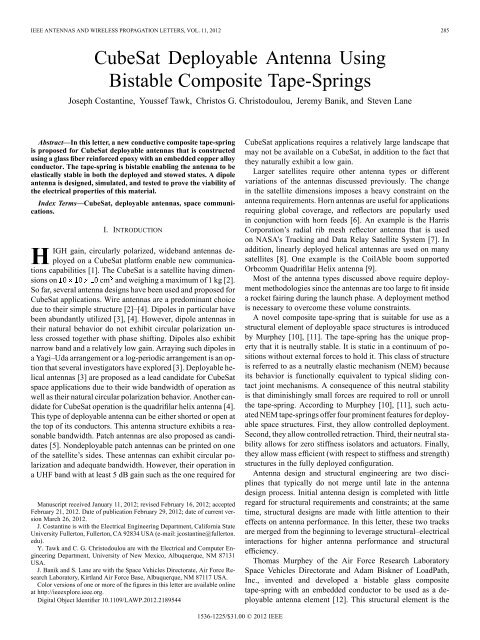
<strong>IEEE</strong> ANTENNAS AND WIRELESS PROPAGATION LETTERS, VOL. 11, 2012 285<br />
<strong>CubeSat</strong> <strong>Deployable</strong> <strong>Antenna</strong> <strong>Using</strong><br />
<strong>Bistable</strong> Composite Tape-Springs<br />
Joseph Costantine, Youssef Tawk, Christos G. Christodoulou, Jeremy Banik, and Steven Lane<br />
Abstract—In this letter, a new conductive composite tape-spring<br />
is proposed for <strong>CubeSat</strong> deployable antennas that is constructed<br />
usingaglassfiber reinforced epoxy with an embedded copper alloy<br />
conductor. The tape-spring is bistable enabling the antenna to be<br />
elastically stable in both the deployed and stowed states. A dipole<br />
antenna is designed, simulated, and tested to prove the viability of<br />
the electrical properties of this material.<br />
Index Terms—<strong>CubeSat</strong>, deployable antennas, space communications.<br />
I. INTRODUCTION<br />
HIGH gain, circularly polarized, wideband antennas deployed<br />
on a <strong>CubeSat</strong> platform enable new communications<br />
capabilities [1]. The <strong>CubeSat</strong> is a satellite having dimensions<br />
on cm and weighing a maximum of 1 kg [2].<br />
So far, several antenna designs have been used and proposed for<br />
<strong>CubeSat</strong> applications. Wire antennas are a predominant choice<br />
due to their simple structure [2]–[4]. Dipoles in particular have<br />
been abundantly utilized [3], [4]. However, dipole antennas in<br />
their natural behavior do not exhibit circular polarization unless<br />
crossed together with phase shifting. Dipoles also exhibit<br />
narrow band and a relatively low gain. Arraying such dipoles in<br />
a Yagi–Uda arrangement or a log-periodic arrangement is an option<br />
that several investigators have explored [3]. <strong>Deployable</strong> helical<br />
antennas [3] are proposed as a lead candidate for <strong>CubeSat</strong><br />
space applications due to their wide bandwidth of operation as<br />
well as their natural circular polarization behavior. Another candidate<br />
for <strong>CubeSat</strong> operation is the quadrifilar helix antenna [4].<br />
This type of deployable antenna can be either shorted or open at<br />
the top of its conductors. This antenna structure exhibits a reasonable<br />
bandwidth. Patch antennas are also proposed as candidates<br />
[5]. Nondeployable patch antennas can be printed on one<br />
of the satellite’s sides. These antennas can exhibit circular polarization<br />
and adequate bandwidth. However, their operation in<br />
a UHF band with at least 5 dB gain such as the one required for<br />
Manuscript received January 11, 2012; revised February 16, 2012; accepted<br />
February 21, 2012. Date of publication February 29, 2012; date of current version<br />
March 26, 2012.<br />
J. Costantine is with the Electrical Engineering Department, California State<br />
University Fullerton, Fullerton, CA 92834 USA (e-mail: jcostantine@fullerton.<br />
edu).<br />
Y. Tawk and C. G. Christodoulou are with the Electrical and Computer Engineering<br />
Department, University of New Mexico, Albuquerque, NM 87131<br />
USA.<br />
J. Banik and S. Lane are with the Space Vehicles Directorate, Air Force Research<br />
Laboratory, Kirtland Air Force Base, Albuquerque, NM 87117 USA.<br />
Color versions of one or more of the figures in this letter are available online<br />
at http://ieeexplore.ieee.org.<br />
Digital Object Identifier 10.1109/LAWP.2012.2189544<br />
<strong>CubeSat</strong> applications requires a relatively large landscape that<br />
may not be available on a <strong>CubeSat</strong>, in addition to the fact that<br />
they naturally exhibit a low gain.<br />
Larger satellites require other antenna types or different<br />
variations of the antennas discussed previously. The change<br />
in the satellite dimensions imposes a heavy constraint on the<br />
antenna requirements. Horn antennas are useful for applications<br />
requiring global coverage, and reflectors are popularly used<br />
in conjunction with horn feeds [6]. An example is the Harris<br />
Corporation’s radial rib mesh reflector antenna that is used<br />
on NASA’s Tracking and Data Relay Satellite System [7]. In<br />
addition, linearly deployed helical antennas are used on many<br />
satellites [8]. One example is the CoilAble boom supported<br />
Orbcomm Quadrifilar Helix antenna [9].<br />
Most of the antenna types discussed above require deployment<br />
methodologies since the antennas are too large to fitinside<br />
a rocket fairing during the launch phase. A deployment method<br />
is necessary to overcome these volume constraints.<br />
A novel composite tape-spring that is suitable for use as a<br />
structural element of deployable space structures is introduced<br />
by Murphey [10], [11]. The tape-spring has the unique property<br />
that it is neutrally stable. It is static in a continuum of positions<br />
without external forces to hold it. This class of structure<br />
is referred to as a neutrally elastic mechanism (NEM) because<br />
its behavior is functionally equivalent to typical sliding contact<br />
joint mechanisms. A consequence of this neutral stability<br />
is that diminishingly small forces are required to roll or unroll<br />
the tape-spring. According to Murphey [10], [11], such actuated<br />
NEM tape-springs offer four prominent features for deployable<br />
space structures. First, they allow controlled deployment.<br />
Second, they allow controlled retraction. Third, their neutral stability<br />
allows for zero stiffness isolators and actuators. Finally,<br />
they allow mass efficient (with respect to stiffness and strength)<br />
structures in the fully deployed configuration.<br />
<strong>Antenna</strong> design and structural engineering are two disciplines<br />
that typically do not merge until late in the antenna<br />
design process. Initial antenna design is completed with little<br />
regard for structural requirements and constraints; at the same<br />
time, structural designs are made with little attention to their<br />
effects on antenna performance. In this letter, these two tracks<br />
are merged from the beginning to leverage structural–electrical<br />
interactions for higher antenna performance and structural<br />
efficiency.<br />
Thomas Murphey of the Air Force Research Laboratory<br />
Space Vehicles Directorate and Adam Biskner of LoadPath,<br />
Inc., invented and developed a bistable glass composite<br />
tape-spring with an embedded conductor to be used as a deployable<br />
antenna element [12]. This structural element is the<br />
1536-1225/$31.00 © 2012 <strong>IEEE</strong>
286 <strong>IEEE</strong> ANTENNAS AND WIRELESS PROPAGATION LETTERS, VOL. 11, 2012<br />
Fig. 1. SIMPLE boom shown in the (a) partially deployed and (b) fully<br />
deployed states [12], [13].<br />
basis for the <strong>CubeSat</strong> communication antenna proposed and<br />
tested in this letter, which constitutes the first measured antenna<br />
designed with bistable composite tape-springs.<br />
Section II of this letter details the composite tape-spring<br />
material. Section III presents the design and measurement of<br />
this tape-spring as a deployable dipole antenna. Section IV<br />
proposes a <strong>CubeSat</strong> antenna concept that could be constructed<br />
using this tape-spring material. Concluding remarks are presented<br />
in Section V.<br />
II. BISTABLE COMPOSITE TAPE-SPRING MATERIAL<br />
The composite tape-spring presented herein is a curved<br />
bistable composite that rolls and unrolls. The composite is<br />
stable in both its deployed and stowed states. Unlike the<br />
neutrally stable tape-spring, the bistable version has only two<br />
elastically stable physical states, fully rolled and fully extended.<br />
The intermediate state can be held stationary, but not without<br />
an external force. Therefore, physical reconfigurability (rolling<br />
and unrolling) can be accomplished with a one-way linear or<br />
rotary actuator, unlike neutrally elastic mechanism (NEM)<br />
tape-springs that require two-way actuators. A deployable<br />
structure concept that utilizes bistable tape-spring elements is<br />
presented in [12] and [13] and shown in Fig. 1.<br />
An expanded cross section of the composite structure is<br />
shown in Fig. 2. It is composed of three plies. The top and<br />
bottom are composed of a 45 biased Astroquartz fabric impregnated<br />
with toughened epoxy. Both layers have an arc width<br />
of 0.5 in. The relative electric permittivity of these two layers<br />
is assumed to be 3.7 [14] at any frequency between 250 and<br />
500 MHz. The relative permeability is assumed to be equal to 1,<br />
and the loss tangent is assumed to be 0.0001 [14]. The middle<br />
layer is composed of a 0.25-in-wide strip of copper alloy and<br />
epoxy filler. Astroquartz is used for its high strain to failure and<br />
low electrical conductivity characteristics. The copper alloy is<br />
used as a compromise between high strain to failure and high<br />
electrical conductivity.<br />
III. DEPLOYABLE DIPOLE WITH BISTABLE<br />
COMPOSITE TAPE-SPRING<br />
<strong>Using</strong> the bistable composite tape-spring discussed previously,<br />
we design a dipole to operate at 250 MHz. To reduce<br />
the simulation processing time in the high frequency structure<br />
Fig. 2. Cross section of the composite tape-spring dipole with a expanded view<br />
of the central part.<br />
Fig. 3.<br />
Dipole with the actual composite tape-spring.<br />
Fig. 4. Simulated dipole structure with the approximated rectangular-shaped<br />
composite tape-spring.<br />
simulator by ANSYS (HFSS), the material is assumed to be of<br />
rectangular shape and not curved. We also assume the beryllium<br />
copper embedded in the middle has a width of 0.25 in. The<br />
total width of each dipole arm is 0.5 in. The total dipole length<br />
is found to be equal to 22 in, which is equivalent to<br />
at 250 MHz. A zoomed-in view of the curved antenna with<br />
the actual material is shown in Fig. 3. The simulated dipole<br />
with the approximated tape-spring is shown in Fig. 4 with a<br />
zoomed-in view of its excitation.<br />
The measurement of this dipole is done by using the image<br />
method [15]. A composite tape-spring quarter-wavelength<br />
monopole approximately around 11 in long is measured on<br />
topofalargegroundplane(45 60 in ) as shown in Fig. 5.
COSTANTINE et al.: <strong>CubeSat</strong> DEPLOYABLE ANTENNA USING BISTABLE COMPOSITE TAPE-SPRINGS 287<br />
Fig. 5.<br />
Measurement setup.<br />
Fig. 7. Comparison between the monopole’s measured reflection coefficient<br />
and the dipole’s simulated reflection coefficient showing great analogy.<br />
Fig. 6.<br />
(a) Deployed and (b) stowed monopole above the ground plane.<br />
A photograph of the deployed (11 in) and stowed (3.4 in)<br />
monopole on top of the ground plane is shown in Fig. 6.<br />
The antenna is rolled and unrolled about 10 times, and the<br />
reflection coefficient is measured each time with no significant<br />
changes, proving that the antenna function is preserved through<br />
mechanical cycles. The comparison between the average measured<br />
reflection coefficient and the simulated data is shown in<br />
Fig. 7. Measurement results of the monopole verify the simulation<br />
approach and the feasibility of using this composite tapespring<br />
structure for antenna design. The simulated three-dimensional<br />
radiation pattern at 250 MHz is shown in Fig. 8.<br />
Fig. 8.<br />
Dipole antenna’s 3-D radiation pattern at 250 MHz.<br />
IV. POTENTIAL CUBESAT ANTENNA CONCEPTS<br />
USING A COMPOSITE TAPE-SPRING<br />
In the previous sections, we proved that a composite tapespring<br />
is a successful candidate for a <strong>CubeSat</strong> deployable antenna<br />
design through simulations and measurements of a deployable<br />
dipole antenna.<br />
Based on all the previously discussed results, we propose<br />
a log-periodic crossed-dipole array antenna designed with the<br />
bistable composite tape-spring proposed in the previous sections.<br />
With a sufficient number of elements, this antenna can<br />
achieve at least 5 dB gain and a frequency band of operation<br />
between 250 and 500 MHz. In addition to these constraints, the<br />
radiation pattern of the proposed antenna is directive away from<br />
Fig. 9. Proposed composite tape-spring log-periodic crossed-dipole antenna<br />
array concept.<br />
the small element where the directivity of this array antenna is<br />
determined by the log periodicity of the elements [15]. This antenna<br />
concept is shown in Fig. 9.<br />
To confirm the validity of the log-periodic design as a good<br />
candidate for <strong>CubeSat</strong>, we simulate a three-element log-periodic<br />
dipole antenna array that is shown in Fig. 10. This antenna operates<br />
between 380 and 500 MHz as shown in Fig. 11. The three
288 <strong>IEEE</strong> ANTENNAS AND WIRELESS PROPAGATION LETTERS, VOL. 11, 2012<br />
Fig. 10. Three-element copper-based log-periodic antenna array with its radiation<br />
pattern at 540 MHz at the E-plane cut.<br />
modeling approach and feasibility as a functional antenna. The<br />
measurement of this dipole is achieved using a quarter-wavelength<br />
tape-spring monopole and image method.<br />
A deployable log-periodic crossed-dipole antenna concept<br />
is proposed as a potential candidate for <strong>CubeSat</strong> applications.<br />
Its radiation pattern characteristics and its gain and bandwidth<br />
prospects confirm its validity for <strong>CubeSat</strong>.<br />
In this letter, we prove that the use of the proposed composite<br />
tape-spring is valid for deployable antenna design. Designing<br />
antennas with this tape-spring constitutes the first step<br />
in merging structural engineering with antenna design concepts.<br />
This merging introduces new deployable antenna possibilities.<br />
The designs based on such composites are proven to be robust,<br />
rigid, and stable to satisfy all the constraints of a <strong>CubeSat</strong><br />
platform.<br />
Fig. 11.<br />
Reflection coefficient of the three-element log-periodic antenna.<br />
elements have lengths of 8.05, 6.5, and 4.78 in, respectively.<br />
The radiation pattern of this antenna array shown in Fig. 10<br />
is directed away from the small element. This is the first step<br />
in completing the proposed crossed-dipole log-periodic array.<br />
Crossing the elements for circular polarization and increasing<br />
their number to improve the bandwidth as well as measuring<br />
the full deployable prototype constitute our next step. All the<br />
resultsshowninFigs.10and11confirm that this deployable<br />
antenna concept is valid for <strong>CubeSat</strong> applications.<br />
V. CONCLUSION<br />
In this letter, a bistable composite tape-spring is proposed to<br />
be used as an antenna element. This element is used in a deployable<br />
dipole antenna concept. The material is bistable, allowing<br />
the antenna to be structurally stable in both the rolled<br />
and unrolled states. The composite tape-spring dipole antenna<br />
is designed, simulated, and measured to show fidelity of the<br />
REFERENCES<br />
[1] H. Heidt, J. Puig-Sauri, A. Moore, S. Nakasuka, and R. Twiggs,<br />
“<strong>CubeSat</strong>: A new generation of Picosatellite for education and<br />
industry low-cost space experimentation,” in Proc. 14th Annu.<br />
AIAA/USU Conf. Small Satell., Logan, UT, Aug. 2000, SSC00-V-5.<br />
[2] H.J.Yousuf,M.M.Haider,M.K.Siddique,andM.Amin,“Analysis<br />
of G-shape antennas mounted on a CUBESAT,” in Proc. 2nd Int. Conf.<br />
Adv. Space Technol., Islamabad, Pakistan, Nov. 2008, vol. 2, pp. 28–32.<br />
[3] P. Muri, C. Obulpathi, and J. McNair, “Enhancing small satellite communication<br />
through effective antenna system design,” in Proc. 2010<br />
Mil. Commun. Conf., Unclassified Program, San Jose, CA, Nov. 2010,<br />
pp. 347–352.<br />
[4] S.Gao,K.Clark,M.Unwin,J.Zackrisson,W.A.Shiroma,J.M.Akagi,<br />
K. Maynard, P. Garner, L. Boccia, G. Amendola, G. Massa, C. Underwood,M.Brenchley,M.Pointer,andM.N.Sweeting,“<strong>Antenna</strong>sfor<br />
modern small satellites,” <strong>IEEE</strong> <strong>Antenna</strong>s Propag. Mag., vol. 51, no. 4,<br />
pp. 40–56, Aug. 2009.<br />
[5] C. G. Kakoyiannis and P. Constantinou, “A compact microstrip<br />
antenna with tapered peripheral slits for <strong>CubeSat</strong> RF payloads at 436<br />
MHz: Miniaturization techniques, design & numerical results,” in<br />
Proc. <strong>IEEE</strong> IWSSC, Toulouse, France, Oct. 2008, pp. 255–259.<br />
[6] T. Kitsuregawa, Advanced Technology in Satellite Communication <strong>Antenna</strong>s.<br />
Norwood, MA: Artech House, 1990, p. 299.<br />
[7] Y. Rahmat-Samii, A. Zaghloul, and A. Williams, “Large deployable<br />
antennas for satellite communications,” in Proc. <strong>Antenna</strong>s Propag. Soc.<br />
Int. Symp., Salt Lake City, UT, Jul. 2000, vol. 2, pp. 528–529.<br />
[8] J. Kraus, <strong>Antenna</strong>s, 2nd ed. New York: McGraw-Hill, 1988, pp.<br />
270–271, 703–709.<br />
[9] ATK, “Coilable boom systems,” Data sheet, Accessed Sep. 29, 2011<br />
[Online]. Available: http://www.atk.com/Products/documents/Coilable%202011.pdf<br />
[10] T. W. Murphey and S. Pellegrino, “A novel actuated composite<br />
tape-spring for deployable structures,” AIAA, Reston, VA, Tech. Rep.<br />
TR-1528, Apr. 2004.<br />
[11] T. W. Murphey, S. Jeon, A. Biskner, and G. Sanford, “<strong>Deployable</strong><br />
booms and antennas using Bi-stable tape-springs,” in Proc. 24th<br />
AIAA/USU Conf. Small Satell., Logan, Utah, SSC10-X-6.2010.<br />
[12] T. W. Murphey, S. Jeon, A. Biskner, and G. Sanford, “<strong>Deployable</strong><br />
booms and antennas using bi-stable tape-springs,” in Proc. 24th<br />
AIAA/USU Conf. Small Satell., Logan, Utah, SSC10-X-6.<br />
[13]S.JeonandT.W.Murphey,“Designandanalysisofameter-class<br />
<strong>CubeSat</strong> boom with a motor-less deployment by bi-stable tape<br />
springs,” in Proc. 52nd AIAA Struct., Struct. Dynam., Mater. Conf.,<br />
Palm Springs, CA, Apr. 4–7, 2011, AIAA-2011-1731.<br />
[14] JPS Composite Materials, “JPS Composite Materials,” 2011 [Online].<br />
Available: http://jpsglass.com/<br />
[15] C. A. Balanis, <strong>Antenna</strong> Theory Analysis and Design, 3rd ed.<br />
Hoboken, NJ: Wiley, 2005.