FPGA-Controlled Switch-Reconfigured Antenna - IEEE Xplore
FPGA-Controlled Switch-Reconfigured Antenna - IEEE Xplore
FPGA-Controlled Switch-Reconfigured Antenna - IEEE Xplore

Create successful ePaper yourself
Turn your PDF publications into a flip-book with our unique Google optimized e-Paper software.
<strong>IEEE</strong> ANTENNAS AND WIRELESS PROPAGATION LETTERS, VOL. 9, 2010 355<strong>FPGA</strong>-<strong>Controlled</strong> <strong>Switch</strong>-<strong>Reconfigured</strong> <strong>Antenna</strong>Severn Shelley, Member, <strong>IEEE</strong>, Joseph Costantine, Member, <strong>IEEE</strong>, Christos G. Christodoulou, Fellow, <strong>IEEE</strong>,Dimitris E. Anagnostou, Member, <strong>IEEE</strong>, and James C. Lyke, Senior Member, <strong>IEEE</strong>Abstract—In this letter, p-i-n diodes are used as switches toconnect and disconnect four patch sections to a midsection of aplanar antenna. The antenna system is connected to the field programmablegate array (<strong>FPGA</strong>) board controlling the activationof these switches. The antenna with the incorporated diodes isdesigned, installed, and measured. The methodology for using an<strong>FPGA</strong> to optimally control and produce the desired antenna frequencyoperation is presented and analyzed. The analogy betweenthe measured and simulated results is found to be satisfactory. Theproposed control methodology can be used with various antennadesigns to obtain different possible states in an easy, fast, andlow-cost manner.Index Terms—Field programmable gate array (<strong>FPGA</strong>),microstrip antennas, reconfigurable antennas.I. INTRODUCTIONRECONFIGURABLE antennas extend the functional possibilitiesof regular antennas by allowing their configurationsto change on demand. The basic idea involves flexibly connectinga series of conductors together (which form the basis ofthe antenna) through switches that are managed under softwarecontrol.The underlying mechanisms for reconfiguration have beenbased on a variety of techniques. More recently, antenna designershave used electrically actuated switches and variable capacitorsin order to achieve reconfiguration [1], [2]. Most antennadesigners resort to RF-MEMS (microelectromechanicalswitches) [3] and p-i-n diodes to achieve switching, while othersresort to Schottky or other types of diodes [4]. In [5], switchesare used to connect different patches together. In [6], five sectionsof a spiral arm constituting a patch antenna are connectedwith four RF-MEMS. In [4], Schottky diodes bridge over a slotto achieve reconfiguration.This letter proposes the reconfiguration of antennas throughthe use of p-i-n diodes that bridge conducting subsections to amain antenna section. The activation and deactivation of thesep-i-n diodes is controlled through a field programmable gateManuscript received February 05, 2010; accepted March 02, 2010. Date ofpublication April 19, 2010; date of current version May 10, 2010.S. Shelley, J. Costantine, and C. G. Christodoulou are with the Electrical andComputer Engineering Department, University of New Mexico, Albuquerque,NM 87131-0001 USA.D. E. Anagnostou is with the Electrical and Computer Engineering Department,South Dakota School of Mines and Technology, Rapid City, SD 57701USA.J. C. Lyke is with the Air Force Research Laboratory, Kirtland Air Force Base,Albuquerque, NM 87117 USA.Color versions of one or more of the figures in this letter are available onlineat http://ieeexplore.ieee.org.Digital Object Identifier 10.1109/LAWP.2010.2048550array (<strong>FPGA</strong>), which manages the overall antenna configurationunder software control. The use of <strong>FPGA</strong> has been previouslyfocused in the field of smart antenna arrays [7], [8] mainlyto control the beam-steering or for signal processing purposes.Here, the <strong>FPGA</strong> is used to control a single antenna that is reconfigurable.The antenna’s design, structure, tuning, and the<strong>FPGA</strong> programming is investigated in the present letter. Thisantenna was fabricated, and the <strong>FPGA</strong>-controlled p-i-n diodeswere tested. The measured results present good correlation withthe simulated data.II. <strong>FPGA</strong>S AND RECONFIGURABLE SYSTEMS<strong>FPGA</strong>s strive to form arbitrary digital systems (arrangementsof logic, memory, and interconnects) by configuring prebuilt circuitfabrics as needed. They are based on a large number oflogic cells, memory blocks, and configurable routing networks[9]. The logic cells typically implement simple Boolean functionsusing lookup tables (LUTs) that each implement the truthtable of a logic function. LUTs can be registered with a clockableflip-flop (useful for constructing state machines) or bypassedto permit the cascadable construction of larger functions.The composition of these elements to form complex networksis achieved through programmable routing resources. These resourcesare large numbers of wires and switches to implementroutable networks that ultimately connect to input/output (I/O)cells that form the external termini (pins) of the <strong>FPGA</strong>. Whilemodern <strong>FPGA</strong>s feature a great variety of other additional functionalblocks (“diffused intellectual property”), ranging fromcarry-select chains to digital signal processing (DSP) blocks andembedded complex microprocessors, the basic scheme is essentiallythe same. That is, <strong>FPGA</strong>s are configurable arrangementsof configurable elements, the overall ensemble having the abilityto represent a complex digital system.The configuration of an entire <strong>FPGA</strong> can be represented as alarge Boolean string called a bit-stream. Commonly, the JointTest Access Group (JTAG) standard [10] is used as a serial configurationapproach for <strong>FPGA</strong>s. While its original intent wasfor test monitoring (through boundary scan), it has been convenientlyused to set binary signals within complex systems. Amajor advantage of using JTAG is that it need not interfere withcircuit functions when not in testing mode. The operation ofJTAG within client devices is governed through a test access port(TAP) controller module, a relatively simple finite state machinedesign directly embedded in the <strong>FPGA</strong> system control logic.One of the useful features of JTAG is the ability to chainthe configuration ports of several devices together and toisolate them individually for programming. Such approachesare commonly used in systems that desire the ability to usea single bit-stream source to contain the configurations formultiple <strong>FPGA</strong>s. An even more powerful interpretation can1536-1225/$26.00 © 2010 <strong>IEEE</strong>
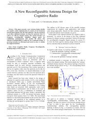
356 <strong>IEEE</strong> ANTENNAS AND WIRELESS PROPAGATION LETTERS, VOL. 9, 2010Fig. 1. Canonical reconfigurable system, based on connection of configurableand nonconfigurable components, controlled by common JTAG scan chain.be supported, however, which is the notion of a generalizedreconfigurable system with multiple components, not all ofwhich are <strong>FPGA</strong>s. Such a reconfigurable system is depictednotionally in Fig. 1. This system is a depiction of a prospectivesoftware-definable radio that consists of five components, ofwhich four are reconfigurable (antenna, low-noise amplifier,IF conversion, and <strong>FPGA</strong>). The reconfigurable elements aremanaged through internal TAP controllers, which are accessedthrough a chained JTAG interface.Reconfigurable systems of the type depicted in Fig. 1 do notcurrently exist, although this interpretation is straightforward.In each component, a number of digitally definable featuresare present, each of which is part of a configuration bit-streamthat, as in the case of the <strong>FPGA</strong>, is of a format particular tothe component. The bit-streams are managed through individualTAP controllers using JTAG to manage the configurations of thecomponents individually and of the system as a whole (sinceits configuration is simply the concatenation of the bit-streamsof individual components). While this letter does not investigatethe detailed structure of a variety of possible reconfigurablebuilding blocks, an example of how a reconfigurable antennamight be constructed is detailed in the next section.III. RECONFIGURABLE ANTENNA STRUCTURE AND TUNINGThe antenna structure consists of three layers; the bottomlayer (90 90 mm ) is a ground plane that covers the entire substrate.The middle substrate has a dielectric constantand a thickness of 0.235 cm. The upper layer is the metal patchcomposed of a main midsection and four surrounding smallersections as shown in Fig. 2. This antenna is fed through a 50-coaxial cable. The feeding position and the antenna dimensionsare shown in Fig. 2(a). A side view of the antenna is shown inFig. 2(b).The variations in configuration are achieved through individuallycontrollable switches, each implemented as a p-i-n diode.Microsemi’s GC 4712 GaAs p-i-n diodes are used to connect thesmall section to the main section as shown in Fig. 2. These p-i-ndiodes operate until 18 GHz and are oriented in the -direction.Connecting the p-i-n diodes to the main section of theantenna are 47-pF capacitors; these capacitors are orientedFig. 2. (a) Front view with different dimensions. (b) Side view of the antenna.in the -direction. The capacitors are used to prevent the dccurrent from crossing into the main section while passing theRF current. Quarter-wavelength transmission lines designedat 7.7 GHz are used to bias the p-i-n diodes. Simulationsshow that these copper lines resonate at a frequency where thelength of the bias lines is approximately and at its oddmultiples, being the effective wavelength at the frequencyof operation. In this case, these lines resonate around 9 GHzand its odd multiples. The directions of the bias lines are alsooptimized to contribute constructively to the radiation patternof the antenna that is reconfigured.These lines are terminated by radial stubs in orderto eliminate interference of the dc biasing network with the radiatingstructure. Biasing these p-i-n diodes separately can connectthe corresponding side sections to the midsection, respectively.The antenna achieves multifrequency resonance tuning,which is shown in Fig. 3. Different switch configurations exhibitdifferent results as shown in Fig. 3. The four configurationsshown in Fig. 3 represent an example of thepossible configurations achieving frequency change. This shiftis noticed at frequencies lower than 3.5 GHz, where a lot ofwireless communications applications can be found, which improvesthe practicality of the design. In Fig. 3, “0” representsthe OFF state of a diode, and “1” represents the ON.Comparisons between the - and -plane cuts (yz, xz planecuts) of the simulated and measured radiation patterns at4.875 GHz when all the switches are OFF are shown in Fig. 4.The radiation pattern is measured at a resonant frequencycommon to all the antenna configurations. It is importantto know that the <strong>FPGA</strong> being behind the ground plane andfar from the antenna does not interfere with the antenna’sradiation pattern or gain. Our experience has shown that mostcare should be taken in dealing with the biasing lines when itcomes to any distortions to the antenna pattern. This antennasystem was simulated with Ansoft HFSS ver. 11. The radiationpattern exhibits changes for different switch configurations.Fig. 5 shows the simulated E-plane cut for two different switchconfigurations at 2.305 GHz.
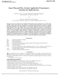
SHELLEY et al.: <strong>FPGA</strong>-CONTROLLED SWITCH-RECONFIGURED ANTENNA 357Fig. 3. <strong>Antenna</strong> resonances for different diode states: 0— OFF, 1—ON.Fig. 6. Photograph of the fabricated prototype.Fig. 7. The parallel III cable with <strong>FPGA</strong> board.Fig. 4. Simulated and measured radiation pattern comparison at 4.875 GHzwith all switches OFF: (a) E-plane cut (yz) and (b) H-plane cut (xz).Fig. 5. Comparison between the E-plane cut (yz) of the simulated radiationpattern for two switch configurations at 2.305 GHz.IV. RECONFIGURABLE ANTENNA FABRICATION,MEASUREMENT, AND <strong>FPGA</strong> CONTROLThe fabricated prototype is shown in Fig. 6. Shorting pinswere inserted into 0.75-mm-diameter holes drilled at the pointof intersection between the p-i-n diodes and the 47-pF capacitors.These shorting pins are used to connect the Microsemi’sGC 4712 GaAs p-i-n diodes to ground. The VCC is connectedto the through pins across holes drilled in the radial stubs. Toimplement the configuration control infrastructure for this configurableantenna, an <strong>FPGA</strong> is used to implement a TAP controlleras suggested in Fig. 1. The <strong>FPGA</strong>’s output lines feed theshorting pins to activate and deactivate the p-i-n diodes.The <strong>FPGA</strong> implements a TAP controller to manage the stateof these outputs using a design consistent with the <strong>IEEE</strong> 1149.1JTAG standard [10]. A Digilent Spartan 3E board with a XilinxSpartan XC3S500E <strong>FPGA</strong> is programmed with the TAP Controllermodule. A Xilinx Parallel III cable is connected from aparallel port on a Linux PC to the JTAG interface pins on theSpartan 3E board [11].Four pins on the Spartan 3E board serve as the outputs fordriving signals to the diode biasing network. The parallel IIIcable as well as the board is shown in Fig. 7.The antenna reconfiguration is achieved through the followingsetup. A Linux computer runs the JTAG software,issuing instructions to a Spartan 3E Xilinx <strong>FPGA</strong> over a ParallelIII cable. The TAP controller programmed on the <strong>FPGA</strong>translates these instructions and asserts the associated signalsto bias the p-i-n diodes on the antenna. The VHDL code used toprogram the <strong>FPGA</strong> was assembled from [12]. With one of thep-i-n diodes biased, the RF signal passes from the main patchthrough the capacitor and that diode to the outer patch.Two comparisons between the simulated and measuredresults are shown in Figs. 8 and 9 for two different configurationsettings, demonstrating a reasonable degree of correlation.
358 <strong>IEEE</strong> ANTENNAS AND WIRELESS PROPAGATION LETTERS, VOL. 9, 2010In this letter, a new approach in reconfigurable systems isdemonstrated using an antenna as an example of a digitallycontrolled component. This antenna is reconfigured using p-i-ndiodes as switches. The diodes connect and disconnect four differentsections of a patch to a main patch to achieve resonancetuning. The control of these p-i-n diodes is achieved through an<strong>FPGA</strong> implementing a TAP controller compliant with the popularJTAG standard.The <strong>FPGA</strong> controlling board constitutes the lower layer ofthe antenna system. The antenna with the incorporated diodesis designed, fabricated, and measured. <strong>FPGA</strong>s are programmedto achieve the control process.The ability to control reconfigurable antennas using computersand programmable devices is now feasible. This developmentin the automated control of reconfigurable antennaswill help in the emergence of future intelligent and self-reconfigurableantenna implementations. Moreover, it is possible tocombine such antennas with other existing (e.g., <strong>FPGA</strong>s) andemerging JTAG-configurable building blocks to make scalable,reconfigurable systems whose total configuration states maybe software definable. These developments suggest the possibilityof more flexible and capable software-definable radios,which have usually focused only on digital signal processingalgorithms in <strong>FPGA</strong>s and have neglected a more expansiveinterpretation of reconfigurable systems.Fig. 8. Measured and simulated jSj comparison for the 0010 antenna state.REFERENCESFig. 9. Measured and simulated jSj comparison for the 0110 antenna state.V. CONCLUSION[1] L. M. Feldner, C. D. Nordquist, and C. G. Christodoulou, “RFMEMSreconfigurable triangular patch antenna,” in Proc. <strong>IEEE</strong> AP/URSI Int.Symp., Jul. 2005, vol. 2A, pp. 388–391.[2] S. L.-S. Yang, A. A. Kishk, and L. Kai-Fong, “Frequency reconfigurableU-slot microstrip patch antenna,” <strong>IEEE</strong> <strong>Antenna</strong>s WirelessPropag. Lett., vol. 7, pp. 127–129, Jan. 2008.[3] D. E. Anagnostou, G. Zheng, M. Chryssomallis, J. Lyke, G. Ponchak,J. Papapolymerou, and C. G. Christodoulou, “Design, fabrication andmeasurements of an RF-MEMS-based self-similar reconfigurableantenna,” <strong>IEEE</strong> Trans. <strong>Antenna</strong>s Propag., vol. 54, no. 2, pt. 1, pp.422–432, Feb. 2006, Special Issue on Multifunction <strong>Antenna</strong>s and<strong>Antenna</strong> Systems.[4] N. Jin, F. Yang, and Y. R. Samii, “A novel patch antenna with switchableslot (PASS): Dual-frequency operation with reversed circularpolarizations,” <strong>IEEE</strong> Trans. <strong>Antenna</strong>s Propag., vol. 54, no. 3, pp.1031–1034, Mar. 2006.[5] W. H. Weedon, W. J. Payne, and G. M. Rebeiz, “MEMS-switched reconfigurableantenna,” in Proc. <strong>IEEE</strong> <strong>Antenna</strong>s Propag. Soc. Symp.,Jul. 2001, vol. 3, pp. 654–657.[6] C. W. Jung, M. C. Lee, G. P. Li, and F. De Flaviis, “Reconfigurablescan beam single arm spiral antenna integrated with RF MEMSswitches,” <strong>IEEE</strong> Trans. <strong>Antenna</strong>s Propag., vol. 54, no. 2, pt. 1, pp.455–463, Feb. 2006.[7] T. W. Nuteson, J. S. Clark, IV, D. S. Haque, and G. S. Mitchell, “Digitalbeamforming and calibration for smart antennas using real-time <strong>FPGA</strong>processing,” in <strong>IEEE</strong> MTT-S Int. Symp. Dig., 2002, vol. 1, pp. 307–310.[8] T. W. Nuteson, J. E. Stocker, J. S. Clark, D. S. Haque, and G. S.Mitchell, “Performance characterization of <strong>FPGA</strong> techniques for calibrationand beamforming in smart antenna applications,” <strong>IEEE</strong> Trans.Microw. Theory Tech., vol. 50, no. 12, pp. 3043–3051, Dec. 2002.[9] P. P. Chu, RTL Hardware Design Using VHDL. Hoboken, NJ: Wiley,2006.[10] “<strong>IEEE</strong> standard test access port and boundary-scan architecture,” [Online].Available: http://standards.ieee.org/reading/ieee/std_public/description/testtech/1149.11990_desc.html[11] “Spartan-3E <strong>FPGA</strong> Starter Kit Board User Guide,” [Online]. Available:http://www.xilinx.com/support/documentation/boards_and_kits/ug230.pdf[12] N. H. E. Weste and D. Harris, CMOS VLSI Design. Boston, MA:Pearson, 2005.