A New Reconfigurable Antenna Design for ... - Cosmiacpubs.org
A New Reconfigurable Antenna Design for ... - Cosmiacpubs.org
A New Reconfigurable Antenna Design for ... - Cosmiacpubs.org

Create successful ePaper yourself
Turn your PDF publications into a flip-book with our unique Google optimized e-Paper software.
This article has been accepted <strong>for</strong> publication in a future issue of this journal, but has not been fully edited. Content may change prior to final publication.<br />
> REPLACE THIS LINE WITH YOUR PAPER IDENTIFICATION NUMBER (DOUBLE-CLICK HERE TO EDIT) < 1<br />
A <strong>New</strong> <strong>Reconfigurable</strong> <strong>Antenna</strong> <strong>Design</strong> <strong>for</strong><br />
Cognitive Radio<br />
Y. Tawk, and C. G. Christodoulou, Member, IEEE<br />
Abstract—This paper presents a new antenna design suitable<br />
<strong>for</strong> cognitive radio communication. It consists of two structures<br />
incorporated together into the same substrate. The first structure<br />
is an ultra wideband antenna covering the spectrum from 3.1<br />
GHz to 11 GHz <strong>for</strong> channel sensing. The second structure is a<br />
frequency reconfigurable triangular shaped patch <strong>for</strong><br />
establishing communication with another RF device. The<br />
antenna reconfigurability is achieved via a rotational motion. A<br />
prototype antenna was fabricated and tested in order to validate<br />
the suggested method.<br />
Index Terms—Cognitive Radio, Frequency <strong>Reconfigurable</strong>,<br />
Rotating Shape, UWB <strong>Antenna</strong><br />
A<br />
I. INTRODUCTION<br />
ccording to the Federal Communications Commission<br />
(FCC), a cognitive radio is “a radio that can change its<br />
transmitter parameters based on interaction with the<br />
environment in which it operates”. Thus, a cognitive radio<br />
should be able to recognize spectrum availability and<br />
reconfigure itself <strong>for</strong> more efficient communications and<br />
spectrum use [1]. The monitoring of the wireless spectrum is<br />
the key in cognitive radio since the spectrum can be idle <strong>for</strong><br />
90% of the time. There<strong>for</strong>e, we should differentiate in such<br />
system between a primary user that owns the spectrum and a<br />
secondary user that wants to access the spectrum whenever it<br />
is idle [2].<br />
Some research has been done related to the design of<br />
antennas <strong>for</strong> cognitive radio systems. In [3], a new technique<br />
is introduced which uses a tunable narrowband Planar<br />
Inverted-F <strong>Antenna</strong> (PIFA). In [4], two reconfigurable<br />
antenna systems both capable of operating in five cellular<br />
radio bands are presented. Both approaches yield overall<br />
improvements in per<strong>for</strong>mance and are likely to be used in<br />
cognitive radios. In [5], a combination of wideband and<br />
narrowband antennas into the same volume is presented. The<br />
wideband antenna is a CPW fed printed hour-glass shaped<br />
monopole which operates from 3 to 11GHz. The narrowband<br />
antenna is a microstrip patch printed on the reverse side of the<br />
substrate, and connected to the wideband antenna via a<br />
shorting pin and designed to operate from 5.15 to 5.35GHz.<br />
Manuscript received November 3, 2009.<br />
Authors are with the Electrical & Computer Engineering Department,<br />
University of <strong>New</strong> Mexico, Albuquerque NM 87131-0001, USA (email:<br />
yatawk, christos@ece.unm.edu).<br />
The authors in [6] discuss some of the possible antenna<br />
requirements <strong>for</strong> cognitive radio applications, and outline<br />
some design approaches. Results <strong>for</strong> three antennas, suitable<br />
<strong>for</strong> small and medium sized terminals, are given.<br />
In this paper a new antenna structure <strong>for</strong> cognitive radio is<br />
presented. In section II, the design of the ultra wideband<br />
antenna <strong>for</strong> channel sensing is presented. Section III discusses<br />
the reconfigurable triangular shaped antenna. In section IV,<br />
we show the final cognitive antenna design which is based on<br />
the two structures that are detailed in section II and III.<br />
II. “SENSING” ANTENNA DESIGN<br />
In cognitive radio system, we need the capability to:<br />
1- Sense the spectrum (“sensing” antenna)<br />
2- Communicate (“reconfigurable communicating”<br />
antenna)<br />
3- Re-sense the spectrum (“sensing” antenna)<br />
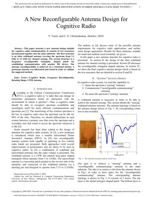
A wideband antenna is necessary in order to be able to<br />
achieve the channel sensing. This section details the “sensing’<br />
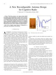
wideband antenna structure. The antenna topology is based on<br />
the antenna design shown in Fig. 1. Its corresponding return<br />
loss is also included.<br />
Fig. 1. The antenna structure and its return loss<br />
Our goal is to achieve a “sensing” antenna and a<br />
“reconfigurable communicating” antenna in the same<br />
substrate. The idea is to remove a slot from the antenna shown<br />
in Fig.1 in order to have space <strong>for</strong> the “reconfigurable<br />
communicating” antenna. The corresponding antenna<br />
topology is shown in Fig. 2. It consists of 2 layers. The top<br />
layer is the slotted polygon shaped patch. The bottom layer is<br />
Copyright (c) 2009 IEEE. Personal use is permitted. For any other purposes, Permission must be obtained from the IEEE by emailing pubs-permissions@ieee.<strong>org</strong>.<br />
Authorized licensed use limited to: UNIVERSITY OF NEW MEXICO. Downloaded on January 12, 2010 at 17:14 from IEEE Xplore. Restrictions apply.
Return Loss (dB)<br />
This article has been accepted <strong>for</strong> publication in a future issue of this journal, but has not been fully edited. Content may change prior to final publication.<br />
> REPLACE THIS LINE WITH YOUR PAPER IDENTIFICATION NUMBER (DOUBLE-CLICK HERE TO EDIT) < 2<br />
the partial ground. It is fed via a microstrip line to produce<br />
radiation above and below the substrate. The chosen substrate<br />
is Rogers Duroid with dielectric constant 2.2 and height 1.6<br />
mm. All simulations were done using HFSS v11. The<br />
corresponding antenna return loss is shown in Fig. 3. It shows<br />
coverage from 3.3 GHz till 11 GHz making it suitable <strong>for</strong><br />
channel sensing in cognitive radio systems.<br />
Fig. 4. The normalized antenna radiation pattern <strong>for</strong> a set of frequencies<br />
Fig. 2. The “Sensing” antenna structure<br />
0<br />
-5<br />
-10<br />
-15<br />
-20<br />
-25<br />
-30<br />
2 4 6<br />
Frequency [GHz]<br />
8 10<br />
x 10 9<br />
Fig. 3. The return loss <strong>for</strong> the sensing antenna structure<br />
For an antenna to be suitable <strong>for</strong> channel sensing it should<br />
possess an omnidirectional radiation pattern. The antenna<br />
structure investigated in this section satisfies this requirement.<br />
The computed radiation pattern in the X-Z plane at 4.5 GHz<br />
(thin line), 7.5 GHz (thick line), and 10.5 GHz (dotted line) is<br />
shown in Fig. 4.<br />
It is essential to note that the addition of the rounded shape<br />
just after the stripline feed line is responsible <strong>for</strong> producing<br />
the required wide bandwidth <strong>for</strong> the antenna. This rounded<br />
shape has the effect of making the antenna input impedance<br />
close to 50 Ω <strong>for</strong> the band from 3.3 GHz till 11 GHz. This<br />
antenna structure also shows a resonance at 1.9 GHz.<br />
III. “RECONFIGURABLE COMMUNICATING” ANTENNA DESIGN<br />
In this section, the structure <strong>for</strong> the “reconfigurable<br />
communicating” antenna is detailed. <strong>Reconfigurable</strong> antennas<br />
have drawn considerable attention especially <strong>for</strong> broadband<br />
wireless communication, space-time adaptive processing,<br />
MIMO systems, and cognitive radio. The reconfigurability is<br />
achieved by using active switches. These switches or tuningelements<br />
can be fabricated from several technologies (MEMS<br />
based, a combination of MEMS and electronic Band-gaps<br />
materials, piezoelectric transducers, PIN diodes, lumped<br />
elements and photoconductive). In this work, we suggest a<br />
new way to implement frequency reconfigurable antenna<br />
design. A rotating part of the antenna is responsible to<br />
produce the required frequency tuning [7]. The advantage of<br />
this method is that no biasing circuits <strong>for</strong> switch activation is<br />
needed which might affect the antenna per<strong>for</strong>mance.<br />
The “reconfigurable communicating” antenna structure is<br />
summarized in Fig. 5. By rotating the antenna patch by 180 o , a<br />
different structure is being fed by the microstrip line. This<br />
rotation will produce different resonances making the antenna<br />
suitable to communicate at the frequency specified by the<br />
“sensing” antenna. The antenna top layer consists of two<br />
triangular shaped patches that are separated by a given<br />
distance. Similar to the “sensing” antenna, this structure is fed<br />
via a microstrip line and has a partial ground. Since this<br />
antenna is going to be incorporated with the “sensing”<br />
antenna, its substrate size was taken the same as the “sensing”<br />
antenna. Its ground dimension is taken to be 18 mm x 9 mm<br />
so that it will not affect the radiation from the patch of the<br />
“sensing” antenna. The process of rotation is shown in Fig. 6;<br />
the structure shown in the left corresponds to position 1 and<br />
the structure shown in the right corresponds to position 2.<br />
The frequency reconfigurability of this antenna can be<br />
noticed by comparing the return loss plot presented in Fig. 7.<br />
This antenna has the property to tune from 5.3 GHz-9.15 GHz<br />
(position 1) to 3.4 GHz-4.85 GHz (position 2). The computed<br />
radiation pattern in the X-Z plane at 6.65 GHz <strong>for</strong> position 1<br />
(thick line) and at 4 GHz <strong>for</strong> position 2 (thin line) is shown in<br />
Fig. 8. For both positions, the antenna satisfies the<br />
omnidirectional property.<br />
Copyright (c) 2009 IEEE. Personal use is permitted. For any other purposes, Permission must be obtained from the IEEE by emailing pubs-permissions@ieee.<strong>org</strong>.<br />
Authorized licensed use limited to: UNIVERSITY OF NEW MEXICO. Downloaded on January 12, 2010 at 17:14 from IEEE Xplore. Restrictions apply.
Return Loss (dB)<br />
Return Loss (dB)<br />
This article has been accepted <strong>for</strong> publication in a future issue of this journal, but has not been fully edited. Content may change prior to final publication.<br />
> REPLACE THIS LINE WITH YOUR PAPER IDENTIFICATION NUMBER (DOUBLE-CLICK HERE TO EDIT) < 3<br />
Fig. 5. The “<strong>Reconfigurable</strong> Communicating” antenna structure<br />
IV. COGNITIVE ANTENNA DESIGN<br />
In the previous two sections, we have separately discussed<br />
the design of the “sensing” and the “reconfigurable<br />
communicating” antenna. In this section, we incorporate both<br />
designs into the same antenna susbtrate. This has the<br />
advantage of reducing space requirements and making the two<br />
antennas required <strong>for</strong> cognitive radio communication to lie in<br />
the same plane.<br />
The suggested antenna structure is provided in Fig. 9. The<br />
dimensions of the different part of the antenna are the same as<br />
those mentioned in the previous two sections. The fabricated<br />
prototype is shown in Fig. 10.<br />
Fig. 6. The process of rotation<br />
Fig. 9. The cognitive antenna structure<br />
0<br />
-5<br />
Position 1<br />
Position 2<br />
-10<br />
-15<br />
-20<br />
-25<br />
-30<br />
-35<br />
2 4 6<br />
Frequency [GHz]<br />
8 10<br />
x 10 9<br />
Fig, 7. Frequency tuning <strong>for</strong> the “reconfigurable communicating” antenna<br />
Fig. 10. The fabricated antenna prototype<br />
The comparison between the simulated and the measured<br />
return loss <strong>for</strong> the “sensing” antenna is shown in Fig. 11. This<br />
data is <strong>for</strong> the antenna at position 1. The same return loss is<br />
produced <strong>for</strong> the “sensing” antenna if the entire antenna<br />
structure is at position 2.<br />
0<br />
-5<br />
Measured<br />
Simulated<br />
-10<br />
-15<br />
-20<br />
-25<br />
-30<br />
-35<br />
Fig. 8. The normalized radiation pattern <strong>for</strong> postion 1 and 2<br />
-40<br />
2 4 6 8 10<br />
Frequency [GHz]<br />
x 10 9<br />
Fig. 11. The “sensing” antenna return loss<br />
Copyright (c) 2009 IEEE. Personal use is permitted. For any other purposes, Permission must be obtained from the IEEE by emailing pubs-permissions@ieee.<strong>org</strong>.<br />
Authorized licensed use limited to: UNIVERSITY OF NEW MEXICO. Downloaded on January 12, 2010 at 17:14 from IEEE Xplore. Restrictions apply.
Return Loss (dB)<br />
Return Loss (dB)<br />
Coupling (dB)<br />
Coupling (dB)<br />
This article has been accepted <strong>for</strong> publication in a future issue of this journal, but has not been fully edited. Content may change prior to final publication.<br />
> REPLACE THIS LINE WITH YOUR PAPER IDENTIFICATION NUMBER (DOUBLE-CLICK HERE TO EDIT) < 4<br />
Fig. 12 shows the measured and the simulated return loss of<br />
the “reconfigurable communicating” antenna <strong>for</strong> both<br />
positions. The required frequency reconfigurability is<br />
achieved. The first plot corresponds to position 2 and covers<br />
the band from 3 GHz to 5 GHz. The second plot corresponds<br />
to position 1 and covers the band from 5 GHz to 9 GHz.<br />
0<br />
-5<br />
-10<br />
-15<br />
-20<br />
Measured<br />
Simulated<br />
-25<br />
2 2.5 3 3.5 4 4.5 5 5.5 6<br />
Frequency [GHz]<br />
x 10 9<br />
0<br />
-10<br />
-20<br />
-30<br />
Measured<br />
Simulated<br />
5 5.5 6 6.5 7 7.5 8 8.5 9<br />
Frequency [GHz]<br />
x 10 9<br />
Fig. 12. The “reconfigurable communicating” return loss <strong>for</strong> both positions<br />
Since the “sensing” and the “reconfigurable communicating”<br />
antennas are both incorporated into the same substrate, it is<br />
crucial to look at the coupling between them. For both<br />
positions, the transmission between the two antennas is below<br />
-10 dB <strong>for</strong> the whole band of interest. Fig. 13 shows the<br />
simulated and the measured coupling <strong>for</strong> position 1 in the first<br />
plot and <strong>for</strong> position 2 in the second plot. The antenna<br />
radiation pattern at 3.5 GHz (position 2, thin line), 5.5 GHz<br />
(position 2, thick line), 7.5 GHz (position 1, dotted thin) and<br />
10.5 GHz (position 1, dotted thick) is shown in Fig. 14.<br />
0<br />
-10<br />
-20<br />
-30<br />
Measured<br />
Simulated<br />
-40<br />
3 4 5 6 7 8 9 10 11<br />
Frequency [GHz]<br />
x 10 9<br />
0<br />
-10<br />
-20<br />
-30<br />
-40<br />
-50<br />
3 4 5 6 7 8 9 10 11<br />
Frequency [GHz]<br />
x 10 9<br />
Fig. 13. The antenna coupling <strong>for</strong> both positions<br />
Measured<br />
Simulated<br />
Fig. 14. The normalized antenna radiation pattern<br />
V. CONCLUSION<br />
In this paper, a new antenna design <strong>for</strong> cognitive radio is<br />
discussed. It consists of two structures. The first one is a<br />
wideband antenna <strong>for</strong> channel sensing. The second structure is<br />
a reconfigurable triangular shaped patch. Both structures are<br />
embedded into the same susbtrate. A prototype antenna was<br />
fabricated to prove the suggested method. A coupling of less<br />
than -10 dB is shown <strong>for</strong> the entire frequency band. This<br />
antenna is a best candidate <strong>for</strong> future cognitive radio<br />
communication. For future work, one can control the rotation<br />
in the “reconfigurable communicating” antenna via a field<br />
programmable gate array (FPGA). Also, the design of the<br />
“sensing antenna” can be done to cover a higher bandwidth<br />
(700 MHz-11 GHz).<br />
REFERENCES<br />
[1] FCC, “Report of the spectrum efficiency working group”, FCC spectrum<br />
policy task <strong>for</strong>ce, Tech. Rep., Nov. 2002.<br />
[2] J. Mitola, “Cognitive Radio: An integrated agent architecture <strong>for</strong><br />
software defined radio”, Ph.D. dissertation, Royal Institute of<br />
Technology (KTH), Stockholm, Sweden, 2000<br />
[3] M. Manteghi, “A switch-band antenna <strong>for</strong> software defined radio<br />
applications”, IEEE <strong>Antenna</strong>s and Wireless Propagation Letters, vol. 8,<br />
pp. 3-5, 2009.<br />
[4] K. R. Boyle, et al., “<strong>Reconfigurable</strong> antennas <strong>for</strong> SDR and cognitive<br />
radio”, The Second European Conference on <strong>Antenna</strong>s and Propagation,<br />
pp. 1-6, Nov. 2007.<br />
[5] E. Ebrahimi, and P. S. Hall, “A dual port wide-narrowband antenna <strong>for</strong><br />
cognitive radio”, The third European Conference on <strong>Antenna</strong>s and<br />
Propagation, pp. 809-812 , Mar. 2009.<br />
[6] P. Gardner, M. R. Hamid, P. S. Hall, J. Kelly, F. Ghanem, and E.<br />
Ebrahimi, “<strong>Reconfigurable</strong> antennas <strong>for</strong> cognitive radio: requirements<br />
and potential design approaches”, Institution of Engineering and<br />
Technology Seminar on Wideband, Multiband <strong>Antenna</strong>s and Arrays <strong>for</strong><br />
Defense or Civil Applications, pp. 89-94, Mar. 2008<br />
[7] Y. Tawk, and C. G. Christodoulou, “A cellular automata reconfigurable<br />
microstrip antenna design”, IEEE <strong>Antenna</strong>s and Propagation Society<br />
International Symposium, pp. 1-4, Jun. 2009.<br />
Copyright (c) 2009 IEEE. Personal use is permitted. For any other purposes, Permission must be obtained from the IEEE by emailing pubs-permissions@ieee.<strong>org</strong>.<br />
Authorized licensed use limited to: UNIVERSITY OF NEW MEXICO. Downloaded on January 12, 2010 at 17:14 from IEEE Xplore. Restrictions apply.