60-2032-4 - Q179A,B Gas Pilot Burner Assemblies
60-2032-4 - Q179A,B Gas Pilot Burner Assemblies
60-2032-4 - Q179A,B Gas Pilot Burner Assemblies

You also want an ePaper? Increase the reach of your titles
YUMPU automatically turns print PDFs into web optimized ePapers that Google loves.
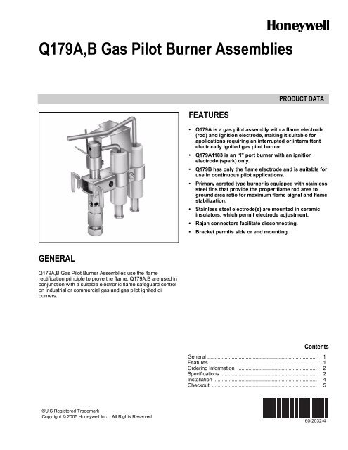
<strong>Q179A</strong>,B <strong>Gas</strong> <strong>Pilot</strong> <strong>Burner</strong> <strong>Assemblies</strong><br />
FEATURES<br />
PRODUCT DATA<br />
• <strong>Q179A</strong> is a gas pilot assembly with a flame electrode<br />
(rod) and ignition electrode, making it suitable for<br />
applications requiring an interrupted or intermittent<br />
electrically ignited gas pilot burner.<br />
• <strong>Q179A</strong>1183 is an “I” port burner with an ignition<br />
electrode (spark) only.<br />
• Q179B has only the flame electrode and is suitable for<br />
use in continuous pilot applications.<br />
• Primary aerated type burner is equipped with stainless<br />
steel fins that provide the proper flame rod area to<br />
ground area ratio for maximum flame signal and flame<br />
stabilization.<br />
• Stainless steel electrode(s) are mounted in ceramic<br />
insulators, which permit electrode adjustment.<br />
• Rajah connectors facilitate disconnecting.<br />
• Bracket permits side or end mounting.<br />
GENERAL<br />
<strong>Q179A</strong>,B <strong>Gas</strong> <strong>Pilot</strong> <strong>Burner</strong> <strong>Assemblies</strong> use the flame<br />
rectification principle to prove the flame. <strong>Q179A</strong>,B are used in<br />
conjunction with a suitable electronic flame safeguard control<br />
on industrial or commercial gas and gas pilot ignited oil<br />
burners.<br />
Contents<br />
General ............................................................................. 1<br />
Features ........................................................................... 1<br />
Ordering Information ........................................................ 2<br />
Specifications ................................................................... 2<br />
Installation ........................................................................ 4<br />
Checkout .......................................................................... 5<br />
®U.S Registered Trademark<br />
Copyright © 2005 Honeywell Inc. All Rights Reserved<br />
<strong>60</strong>-<strong>2032</strong>-4
<strong>Q179A</strong>,B GAS PILOT BURNER ASSEMBLIES<br />
SPECIFICATIONS<br />
Model Number:<br />
<strong>Q179A</strong>—<strong>Gas</strong> pilot assembly with ignition and flame electrodes.<br />
Use with intermittent or interrupted ignition. Ignition<br />
electrode is for use with 6,000V grounded secondary-ignition<br />
transformer. (<strong>Q179A</strong>1183 has ignition electrode [spark]<br />
only.)<br />
Q179B—<strong>Gas</strong> pilot assembly with flame electrode (rod) only.<br />
Use with continuous pilot.<br />
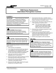
Maximum Temperature:<br />
See Fig. 3.<br />
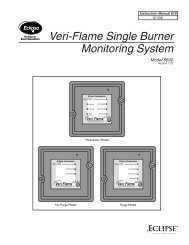
E<br />
45° LEFT<br />
HAND "ELL"<br />
<strong>Burner</strong>:<br />
Primary aerated. Stainless steel fins provide proper flame contact<br />
area to ground area. Flame electrode and ground<br />
bracket are furnished with each tip. Available tips are illustrated<br />
in Fig. 1, and listed in Table 1.<br />
A<br />
"I" PORT<br />
Mounting Means:<br />
Bracket has holes for side mounting and two lugs for end<br />
mounting.<br />
1<br />
F<br />
"T" PORT<br />
Type of <strong>Gas</strong>:<br />
Natural; for LP gas, order LP orifice separately (see<br />
Accessories).<br />
B<br />
45° "I" PORT<br />
<strong>Gas</strong> Consumption:<br />
Approximately two cu ft/hr.<br />
G<br />
45° "Y" PORT<br />
Electrodes:<br />
Stainless steel, maximum temperature 1750°F (954°C).<br />
Electrode Insulator(s):<br />
Ceramic.<br />
D<br />
45° RIGHT HAND "ELL"<br />
Electrical Connector:<br />
Rajah connector (both male and female supplied).<br />
H<br />
45° "T" PORT<br />
Approvals:<br />
Underwriters Laboratories Inc. listed, File No. MP268;<br />
Industrial Risk Insurers acceptable;<br />
CSA certified, Master File No. LR-95329-1;<br />
Factory Mutual approved;<br />
American <strong>Gas</strong> Association certified, No. G140.401.<br />
Mounting Dimensions:<br />
See Fig. 2.<br />
1 NOTE THAT GROUND PRONG<br />
IS CUT OFF CLOSE TO BASE.<br />
M5007<br />
Fig. 1. <strong>Pilot</strong> tip assembly styles.<br />
ORDERING INFORMATION<br />
When purchasing replacement and modernization products from your TRADELINE® wholesaler or distributor, refer to the<br />
TRADELINE® Catalog or price sheets for complete ordering number, or specify:<br />
1. Order numbr<br />
2. <strong>Burner</strong> tip<br />
3. Thermocouple, collar, and bracket, if desired, for Q1879B<br />
4. High temperature cable, if required.<br />
If you have additional questions, need further information, or would like to comment on our products or services, please write or<br />
phone:<br />
1. Your local Honeywell Automation and Control Products Sales Office (check white pages of your phone directory).<br />
2. Honeywell Customer Care<br />
1885 Douglas Drive North<br />
Minneapolis, Minnesota 55422-4386<br />
In Canada—Honeywell Limited/Honeywell Limitée, 35 Dynamic Drive, Scarborough, Ontario M1V 4Z9.<br />
International Sales and Service Offices in all principal cities of the world. Manufacturing in Australia, Canada, Finland, France,<br />
Germany, Japan, Mexico, Netherlands, Spain, Taiwan, United Kingdom, U.S.A.<br />
<strong>60</strong>-<strong>2032</strong>—4 2
<strong>Q179A</strong>,B GAS PILOT BURNER ASSEMBLIES<br />
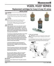
MOUNTING<br />
EARS<br />
FOR END<br />
MOUNTING<br />
LOCATION OF<br />
OPTIONAL<br />
THERMOCOUPLE<br />
1-1/2<br />
(38)<br />
1-5/16<br />
(33)<br />
2<br />
FLAME ELECTRODE<br />
GROUND BRACKET<br />
IGNITION ELECTRODE<br />
(ON <strong>Q179A</strong> ONLY)<br />
ELECTRODE<br />
INSULATORS<br />
CLAMP SCREW<br />
INSULATOR<br />
BRACKET<br />
3<br />
7/32<br />
(6)<br />
1-3/16 (30)<br />
1-11/16 (43)<br />
4-7/64<br />
(104)<br />
1<br />
13/32<br />
(10)<br />
13/32<br />
(10)<br />
1-29/32 (48)<br />
3 (74)<br />
7/32 (6)<br />
MOUNTING<br />
HOLES -<br />
7/32 DIA.<br />
FOR SIDE<br />
MOUNTING<br />
1<br />
2<br />
3<br />
THIS DIMENSION WILL VARY DEPENDING<br />
ON THE FLAME ELECTRODE AND INLET<br />
FITTING USED. FORMATION OF THE<br />
FLAME ELECTRODE AND GROUND FINS<br />
WILL VARY WITH THE BURNER TIP USED.<br />
GAP BETWEEN IGNITION ELECTRODE AND<br />
BURNER TIP MUST BE 1/16 TO 3/32 INCH.<br />
<strong>Q179A</strong>1183 DOES NOT HAVE FLAME<br />
ELECTRODE OR GROUND BRACKET.<br />
M24193<br />
Fig. 2. Approximate mounting dimensions in in. (mm) and arrangement of parts.<br />
GROUND<br />
SHIELD<br />
1300F (704C)<br />
FLAME<br />
ELECTRODE<br />
1750F (954C)<br />
<strong>Q179A</strong><br />
Inlet Fittings:<br />
1/4 inch compression coupling factory-installed on all models.<br />
Replacement Parts (See Table 1):<br />
37356 Rajah Connector—for ignition electrode.<br />
104312 Rajah Connector—for flame electrode.<br />
133445A Ignition Electrode and Insulator Assembly.<br />
PILOT<br />
BURNER TIP<br />
1500F (816C)<br />
INSULATOR<br />
1050F (566C)<br />
IGNITION<br />
ELECTRODE<br />
1750F (954C)<br />
Accessories:<br />
High temperature (higher than 125°F [52°C]) cable:<br />
Flame Rod Leadwire—part no. R1298020 (specify length)<br />
rated at 400°F (204°C).<br />
Ignition Leadwire—part no. R1061012 (specify length), rated at<br />
350°F (177°C).<br />
High Tension Cable—part no. R1239001 (specify length), rated<br />
at 220°F (104°C).<br />
PILOT<br />
ORIFICE<br />
780F (416C)<br />
IGNITION<br />
CONNECTOR<br />
750F (399C)<br />
FLAME<br />
ELECTRODE<br />
CONNECTOR<br />
750F (399C)<br />
M7859<br />
Fig. 3. Component maximum temperature ratings.<br />
3 <strong>60</strong>-<strong>2032</strong>—4
<strong>Q179A</strong>,B GAS PILOT BURNER ASSEMBLIES<br />
a On some ground areas, one or more prongs were intentionally removed at the factory.<br />
b Orifice 0.025 in. (0.635 mm) diameter.<br />
c Orifice 0.0130 in. (0.330 mm) diameter (order separately).<br />
d Orifice 0.028 in. (0.711 mm) diameter.<br />
Table 1. Additional <strong>Q179A</strong>, B Replacement Parts<br />
Ground and<br />
Orifice<br />
Flame Rod and<br />
Assembly Tip Style Tip Ground Shield a Natural <strong>Gas</strong> LP <strong>Gas</strong> Insulator Assembly<br />
I 105063A 102464A 395390-25 b 395390-13 c 133448A<br />
45° I 105064A 102464B 395390-25 b 133450A<br />
45° RH 105066A 120464D 395390-25 b 133452A<br />
45° LH 105067A 102464D 395390-25 b 133444A<br />
T 105068A 102464F 395390-28 d 133451A<br />
45° Y 105069A 102464C 395390-28 d 133446A<br />
45° T 105070A 102464H 395390-28 d 133452A<br />
Large I 121831A 102464A 395390-25 b 133448A<br />
INSTALLATION<br />
When Installing this Product…<br />
1. Read these instructions carefully. Failure to follow them<br />
could damage the product or cause a hazardous<br />
condition.<br />
2. Check the ratings given in the instructions and on the<br />
product to make sure the product is suitable for your<br />
application.<br />
3. Installer must be a trained, experienced, flame safeguard<br />
control technician.<br />
4. After installation is complete, check out product operation<br />
as provided in these instructions.<br />
Follow instructions provided by burner manufacturer if<br />
available. If no instructions are furnished, use the following<br />
recommendations.<br />
Mounting<br />
The Q179 has two mounting ears at the burner and two<br />
mounting holes in the bracket (see Fig. 2). If the mounting<br />
holes in the bracket are used, it may be necessary to break off<br />
one of the mounting ears so that the bracket fits flush with the<br />
burner.<br />
All models are supplied with a factory-installed 1/4 inch<br />
compression coupling inlet fitting. When a fitting is used,<br />
remove the compression nut and install the new fitting.<br />
<strong>Gas</strong> Pressure Regulation<br />
Use a pressure regulator in the line supplying the Q179 pilot.<br />
Adjust the regulator for a maximum inlet gas pressure of eight<br />
inches water column. The minimum inlet gas pressure must be<br />
two inches water column to assure reliable lightoff of the main<br />
flame.<br />
Install the <strong>Q179A</strong>,B<br />
Install the pilot assembly so the pilot flame has full contact with<br />
the gas stream from the main burner heads or jets. Mount the<br />
flame electrode just inside the junction of the main and pilot<br />
flame to prove both flames. Mount the pilot so that it fires in the<br />
same direction as the draft at the mounting point, rather than<br />
where the draft is at right angles to flame travel. Keep the pilot<br />
burner below or behind the main burner so that the burner<br />
frame and refractory will help protect the pilot from radiant<br />
heat. Locating the pilot in the secondary air stream will also<br />
provide considerable cooling. The primary air adjustment must<br />
be accessible and outside the high temperature area.<br />
Do Not Install the <strong>Q179A</strong>,B—<br />
— Where ambient temperatures exceed those specified in<br />
Fig. 3.<br />
— Where excessive draft turbulence can deflect the pilot<br />
flame away from the main burner or flame electrode.<br />
— Where the ignition electrode is within arcing distance of<br />
any metal other than the pilot burner head.<br />
— Where the flame electrode contacts any metal part of<br />
the installation.<br />
— Where the flame electrode is closer than one inch from<br />
a radiant refractory.<br />
WIRING<br />
CAUTION<br />
Disconnect power supply to prevent electrical<br />
shock and equipment damage. More than one<br />
disconnect may be involved. Wiring must conform<br />
to local codes and ordinances.<br />
Rajah connectors are furnished for making connections to the<br />
ignition and flame electrodes. The ignition electrode (A models<br />
only) takes a receptacle connector. The flame electrode (both<br />
A and B models) takes a plug connector and has a snap-action<br />
spring terminal.<br />
<strong>60</strong>-<strong>2032</strong>—4 4
<strong>Q179A</strong>,B GAS PILOT BURNER ASSEMBLIES<br />
Use high tension wire, of a type found acceptable by a<br />
nationally recognized testing agency, for the wiring to the<br />
ignition electrode (<strong>Q179A</strong>). High tension wires should be rated<br />
electrically equivalent to type GTO-10 and should have<br />
temperature and humidity characteristics adequate for the<br />
application. If the ignition lead is exposed to temperatures<br />
above 125°F (52°C), use Honeywell R1061012 Ignition Cable<br />
rated at 350°F (177°C) or equivalent. For ignition installations<br />
in a contaminated environment, use Honeywell R1239001<br />
High Tension Cable rated at 220°F (104°C) or equivalent.<br />
For wiring between the F terminal of the relay and the flame<br />
electrode, use wire with moisture-resistant insulation. Number<br />
14 single-conductor TW wire is adequate; however, those<br />
portions of the leadwire exposed to temperatures over 125°F<br />
(52°C) should also be heat resistant. For both heat and<br />
moisture-resistant applications, use part no. R1298020 Flame<br />
Rod Leadwire rated at 400°F (204°C) continuous duty or<br />
equivalent.<br />
Run a ground wire from the pilot burner to the relay to assure a<br />
continuous, unchanging ground.<br />
For detailed wiring diagrams, see the Instructions packed with<br />
the flame safeguard control.<br />
CHECKOUT<br />
CAUTION<br />
Check to ensure the main valve opens only when<br />
the pilot flame is strong enough to ignite the main<br />
burner. Perform the pilot turn-down test as<br />
described in the Honeywell Flame Safeguard<br />
Control instructions.<br />
The proper pilot burner orifice must be selected for the gas<br />
being used (natural, LP gas) so that the pilot burns with a<br />
medium hard flame. This type of flame provides the maximum<br />
flame signal.<br />
The flame safeguard control relay will chatter if excess<br />
secondary air velocity or a severe draft condition causes the<br />
pilot flame to make intermittent contact with the flame electrode<br />
(rod) or grounding bracket.<br />
available, a dc ammeter with a 0 to 25 microampere scale can<br />
be wired in series with the F lead of the flame detector circuit.<br />
A minimum flame current of 2.0 microamperes is considered<br />
acceptable.<br />
The Honeywell BCS 7700 and 7800 SERIES Flame Safeguard<br />
Control flame signals are measured in dc volts. A 20,000 volt/<br />
ohm meter with a 0 to 5 or 10 Vdc scale is recommended for<br />
measuring the flame signal of BCS 7700 controls while a one<br />
megohm/volt meter is recommended for 7800 SERIES<br />
controls. The flame signal voltages are measured as illustrated<br />
in Fig. 5 and 6.<br />
The minimum acceptable flame signal voltage for the BCS<br />
7700 controls is 2.2 Vdc (maximum expected is 4.98 Vdc).<br />
The minimum acceptable flame signal voltage for the 7800<br />
SERIES controls is 1.25 Vdc (maximum expected is 5.0 Vdc).<br />
If the flame signal is less than the minimum acceptable for the<br />
Honeywell Flame Safeguard Control used, adjust the flame<br />
electrode (rod) to increase the flame signal to at least the<br />
minimum acceptable level by loosening the clamp screw and<br />
turning the electrode (rod) slightly to the right or left as<br />
required. After the flame electrode (rod) is adjusted, check the<br />
gap between the ignition electrode and burner tip (<strong>Q179A</strong>).<br />
The gap must be between 1/16 and 3/32 inch.<br />
Perform the pilot turndown test as described in the Flame<br />
Safeguard Control Instructions to ensure the pilot flame is<br />
adequate to ignite the main burner.<br />
W136A VOLT-<br />
OHMMETER<br />
W136A SELECTOR<br />
SWITCH<br />
196146 METER<br />
CONNECTOR<br />
PLUG<br />
PLUG<br />
FLAME SIGNAL<br />
METER JACK<br />
The performance of the pilot assembly can be determined by<br />
measuring the flame signal developed with the pilot operating.<br />
The flame signal (current/voltage) measurement requires the<br />
use of an appropriate volt-ohmmeter.<br />
RED (+)<br />
METER<br />
LEAD<br />
BLACK (–) METER LEAD<br />
RED CONNECTOR<br />
BLACK CONNECTOR<br />
PLUG-IN FLAME<br />
SIGNAL AMPLIFIER<br />
M6532A<br />
Most existing Honeywell Flame Safeguard Controls<br />
incorporate a flame current jack in the control plug-in amplifier<br />
or in the control itself. The flame current measurement can be<br />
made with a Honeywell W136A Test Meter, which has a 0 to 25<br />
microampere dc scale (see Fig. 4). With the W136A selector<br />
switch positioned to the 0 to 25 microampere scale, connect<br />
the meter leads to the two ends of the meter connector plug,<br />
positive (red, +) to positive, negative (black, -) to negative. The<br />
Meter Connector Plug part no. 196146 is provided with the<br />
W136A Meter. If a W136A Meter or connector plug is not<br />
Fig. 4. Measuring microamp flame signal.<br />
<strong>Pilot</strong> Turndown Test<br />
If the flame rod is used to prove a pilot flame before the main<br />
fuel valve(s) can be opened, perform a pilot turndown test.<br />
Follow the procedures in the Instructions for the appropriate<br />
Flame Safeguard Control, and in the burner manufacturer’s<br />
instructions.<br />
5 <strong>60</strong>-<strong>2032</strong>—4
<strong>Q179A</strong>,B GAS PILOT BURNER ASSEMBLIES<br />
RESET<br />
BUTTON<br />
PROGRAM<br />
MODULE<br />
NEGATIVE (-)<br />
METER LEAD<br />
POSITIVE (+)<br />
METER LEAD<br />
ONE MEGOHM/VOLT<br />
METER<br />
20,000<br />
VOLT/OHM<br />
METER<br />
METER<br />
PROBES<br />
FLAME<br />
AMPLIFIER<br />
BCS 7700 CHASSIS MODULE FOOT MOUNT<br />
M78<strong>60</strong><br />
M7382<br />
Fig. 5. Measuring BCS 7700 Control flame signal voltage.<br />
Fig. 6. Measuring 7800 SERIES Control flame signal<br />
voltage.<br />
<strong>60</strong>-<strong>2032</strong>—4 6
<strong>Q179A</strong>,B GAS PILOT BURNER ASSEMBLIES<br />
7 <strong>60</strong>-<strong>2032</strong>—4
<strong>Q179A</strong>,B GAS PILOT BURNER ASSEMBLIES<br />
Automation and Control Solutions<br />
Honeywell International Inc. Honeywell Limited-Honeywell Limitée<br />
1985 Douglas Drive North 35 Dynamic Drive<br />
Golden Valley, MN 55422 Scarborough, Ontario M1V 4Z9<br />
customer.honeywell.com<br />
® U.S. Registered Trademark<br />
© 2005 Honeywell International Inc.<br />
<strong>60</strong>-<strong>2032</strong>—4 M.S. Rev. 11-05