compressor Pump Safety Warnings - Harbor Freight Tools
compressor Pump Safety Warnings - Harbor Freight Tools
compressor Pump Safety Warnings - Harbor Freight Tools

You also want an ePaper? Increase the reach of your titles
YUMPU automatically turns print PDFs into web optimized ePapers that Google loves.
Table of Contents<br />
<strong>Safety</strong> ......................................................... 2<br />
Specifications.............................................. 5<br />
Instructions for putting into use................... 6<br />
Maintenance .............................................. 11<br />
Parts List and Diagram............................... 14<br />
Warranty..................................................... 16<br />
<strong>Safety</strong> Setup<br />
Maintenance PARTS LIST<br />
WARNING SYMBOLS AND DEFINITIONS<br />
This is the safety alert symbol. It is used to alert you to potential personal injury hazards.<br />
Obey all safety messages that follow this symbol to avoid possible injury or death.<br />
Indicates a hazardous situation which, if not avoided,<br />
will result in death or serious injury.<br />
Indicates a hazardous situation which, if not avoided,<br />
could result in death or serious injury.<br />
Indicates a hazardous situation which, if not avoided,<br />
could result in minor or moderate injury.<br />
Addresses practices not related to personal injury.<br />
IMPORTANT SAFETY INFORMATION<br />
General <strong>Safety</strong> <strong>Warnings</strong><br />
WARNING Read all safety warnings and instructions.<br />
Failure to follow the warnings and instructions may result in electric shock, fire and/or serious injury.<br />
Save all warnings and instructions for future reference.<br />
The warnings, precautions, and instructions discussed in this instruction manual cannot cover all possible<br />
conditions and situations that may occur. It must be understood by the operator that common sense<br />
and caution are factors which cannot be built into this product, but must be supplied by the operator.<br />
1. Work area safety<br />
a. Keep work area clean and well lit.<br />
Cluttered or dark areas invite accidents.<br />
b. Do not operate the Compressor <strong>Pump</strong> in<br />
explosive atmospheres, such as in the<br />
presence of flammable liquids, gases or dust.<br />
Compressor pump motors produce sparks<br />
which may ignite the dust or fumes.<br />
c. Keep children and bystanders away<br />
from an operating <strong>compressor</strong> pump.<br />
2. Personal safety<br />
a. Stay alert, watch what you are doing<br />
and use common sense when operating<br />
this <strong>compressor</strong> pump. Do not use this<br />
<strong>compressor</strong> pump while you are tired<br />
or under the influence of drugs, alcohol<br />
or medication. A moment of inattention<br />
while operating a <strong>compressor</strong> pump may<br />
result in serious personal injury.<br />
b. Use personal protective equipment.<br />
Always wear ANSI-approved eye<br />
protection during setup and use.<br />
Page 2 For technical questions, please call 1-800-444-3353. Item 67698
General <strong>Safety</strong> <strong>Warnings</strong> (continued)<br />
3. Compressor <strong>Pump</strong> use and care<br />
a. Disconnect the plug of the <strong>compressor</strong><br />
motor from the power source before<br />
installing, making any adjustments, changing<br />
accessories, or storing the Compressor<br />
<strong>Pump</strong>. Such preventive safety measures<br />
reduce the risk of starting the unit accidentally.<br />
b. Store an idle <strong>compressor</strong> pump out of the<br />
reach of children and do not allow persons<br />
unfamiliar with the <strong>compressor</strong> pump or these<br />
instructions to operate it. A <strong>compressor</strong> pump<br />
is dangerous in the hands of untrained users.<br />
c. Maintain the Compressor <strong>Pump</strong>. Keep the<br />
Compressor <strong>Pump</strong> clean for better and<br />
safer performance. Follow instructions<br />
for lubricating and changing accessories.<br />
Keep dry, clean and free from oil and grease.<br />
Check for misalignment or binding of moving<br />
parts, breakage of parts and any other<br />
condition that may affect the <strong>compressor</strong>’s<br />
operation. If damaged, have the <strong>compressor</strong><br />
repaired before use. Many accidents are caused<br />
by a poorly maintained <strong>compressor</strong> pump.<br />
d. Use the Compressor <strong>Pump</strong> in accordance<br />
with these instructions, taking into account<br />
the working conditions and the work to be<br />
performed. Use of the Compressor <strong>Pump</strong><br />
for operations different from those intended<br />
could result in a hazardous situation.<br />
4. Service<br />
a. Have the Compressor <strong>Pump</strong> serviced by a<br />
qualified repair person using only identical<br />
replacement parts. This will ensure that the<br />
safety of the Compressor <strong>Pump</strong> is maintained.<br />
<strong>Safety</strong><br />
Compressor <strong>Pump</strong> <strong>Safety</strong> <strong>Warnings</strong><br />
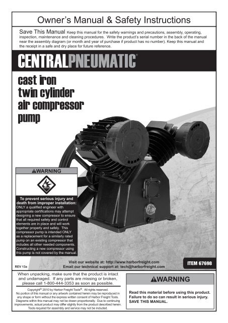
1. ONLY a qualified engineer with appropriate<br />
certifications may attempt designing a new<br />
<strong>compressor</strong> to ensure that all required safety<br />
and control elements are in place and will work<br />
together properly and safely. This <strong>compressor</strong><br />
pump is intended ONLY as a replacement<br />
for a similarly rated pump on an existing<br />
<strong>compressor</strong> that includes all other needed<br />
components. Constructing a new <strong>compressor</strong><br />
using this pump is not covered by this manual.<br />
2. Use <strong>Safety</strong> Guard for Pulleys. The Air<br />
Compressor <strong>Pump</strong> Pulley (58), V-belts (not<br />
included), and motor pulley (not included) must<br />
be covered by a safety guard (not included)<br />
covering all moving elements before operation.<br />
3. Before first and every use, verify<br />
<strong>Pump</strong> has sufficient oil.<br />
4. The use of accessories or attachments not<br />
recommended by the manufacturer may<br />
result in a risk of injury to persons.<br />
5. Misalignment between Motor and <strong>Pump</strong><br />
can damage the <strong>Pump</strong> Pulley. Use a<br />
straight edge, such as a yardstick, to check<br />
and adjust alignment as needed.<br />
6. Use proper size motor and motor pulley.<br />
This Air Compressor <strong>Pump</strong> must be installed<br />
with a 5 HP electric motor and pulley (both not<br />
included) which can turn the Air Compressor<br />
<strong>Pump</strong> Pulley at approximately 1050 rpm.<br />
7. Install motor, pulley belts and pulley belt<br />
cover securely. Be sure to use the proper size<br />
bolts to install the motor (not included). The belts<br />
and belt cover (not included) must be strong<br />
enough to prevent breaking and possible injury.<br />
8. Be sure all equipment is rated to the<br />
appropriate capacity of this pump. Make sure<br />
that the lowest rated piece of equipment being<br />
used can handle the maximum pressure of the<br />
Air Compressor <strong>Pump</strong> (see Specifications).<br />
9. Do not direct the air stream at<br />
any person or animal.<br />
10. Avoid burns. The Cylinders (22), Cylinder<br />
Heads (6) and Air Outlet components become<br />
very hot during operation. Do not touch.<br />
11. Industrial applications must follow OSHA guidelines.<br />
12. Maintain labels and nameplates on the<br />
Compressor <strong>Pump</strong>. These carry important safety<br />
information. If unreadable or missing, contact<br />
<strong>Harbor</strong> <strong>Freight</strong> <strong>Tools</strong> for a replacement.<br />
13. This product is not a toy.<br />
Keep it out of reach of children.<br />
14. WARNING: The brass components of<br />
this product contain lead, a chemical<br />
known to the State of California to cause<br />
birth defects (or other reproductive harm).<br />
(California Health & <strong>Safety</strong> code § 25249.5, et seq.)<br />
PARTS LIST Maintenance<br />
Setup<br />
Item 67698<br />
For technical questions, please call 1-800-444-3353.<br />
Page 3
Air Compressor <strong>Safety</strong> <strong>Warnings</strong><br />
<strong>Safety</strong> Setup<br />
Maintenance PARTS LIST<br />
1. Risk of fire or explosion - do not spray flammable<br />
liquid in a confined area or towards a hot surface.<br />
Spray area must be well‐ventilated. Do not<br />
smoke while spraying or spray where spark or<br />
flame is present. Arcing parts - keep <strong>compressor</strong><br />
at least 20 feet away from explosive vapors,<br />
such as when spraying with a spray gun.<br />
2. Risk of bursting - do not adjust regulator higher<br />
than marked maximum pressure of attachment.<br />
3. Risk of injury - do not direct air<br />
stream at people or animals.<br />
4. Do not use to supply breathing air.<br />
5. Do not leave <strong>compressor</strong> unattended<br />
for an extended period while plugged in.<br />
Unplug <strong>compressor</strong> after working.<br />
6. Keep <strong>compressor</strong> well-ventilated.<br />
Do not cover <strong>compressor</strong> during use.<br />
7. Drain tank daily and after use. Internal rust causes<br />
tank failure and explosion.<br />
8. Add correct amount of <strong>compressor</strong> oil before first<br />
use and every use. Operating with low or no oil<br />
causes permanent damage and voids warranty.<br />
9. Do not remove the valve cover or<br />
adjust internal components.<br />
10. Compressor head gets hot during operation.<br />
Do not touch it or allow children nearby during<br />
or immediately following operation.<br />
11. Do not use the air hose to move the <strong>compressor</strong>.<br />
12. Release the pressure in the<br />
storage tank before moving.<br />
13. The use of accessories or attachments not<br />
recommended by the manufacturer may<br />
result in a risk of injury to persons.<br />
14. All air line components, including hoses, pipe,<br />
connectors, filters, etc., must be rated for a minimum<br />
working pressure of 150 PSI, or 150% of the<br />
maximum system pressure, whichever is greater.<br />
15. USE OF AN EXTENSION CORD IS NOT<br />
RECOMMENDED. If you choose to use an<br />
extension cord, use the following guidelines:<br />
Table A: RECOMMENDED MINIMUM WIRE<br />
GAUGE FOR EXTENSION CORDS<br />
(120 VOLT)<br />
NAMEPLATE<br />
AMPERES<br />
(at full load)<br />
EXTENSION CORD<br />
LENGTH<br />
25′ 50′ 100′ 150′<br />
0 – 6 18 16 16 14<br />
6.1 – 10 18 16 Do not use.<br />
10.1 – 12 16 16 Do not use.<br />
12.1 – 16 14 12 Do not use.<br />
a. Make sure your extension cord<br />
is in good condition.<br />
b. Be sure to use an extension cord which is heavy<br />
enough to carry the current your product will draw.<br />
An undersized cord will cause a drop in line<br />
voltage resulting in loss of power and overheating.<br />
Table A shows the correct size to use depending<br />
on cord length and nameplate ampere rating.<br />
If in doubt, use the next heavier gauge. The<br />
smaller the gauge number, the heavier the cord.<br />
16. Operate unit on level surface. Check oil level<br />
daily and fill to marked level if needed.<br />
17. People with pacemakers should consult their<br />
physician(s) before use. Electromagnetic fields in<br />
close proximity to heart pacemaker could cause<br />
pacemaker interference or pacemaker failure.<br />
SAVE THESE INSTRUCTIONS.<br />
Page 4 For technical questions, please call 1-800-444-3353. Item 67698
Grounding<br />
TO PREVENT ELECTRIC SHOCK AND DEATH<br />
FROM INCORRECT GROUNDING WIRE CONNECTION:<br />
Check with a qualified electrician if you are in doubt as to whether the outlet is properly grounded.<br />
Do not modify the power cord plug provided with any motor used with this Compressor <strong>Pump</strong>.<br />
Never remove the grounding prong from the plug. Do not use the motor if the power cord or plug is damaged.<br />
If damaged, have it repaired by a service facility before use. If the plug will not fit the outlet, have a proper<br />
outlet installed by a qualified electrician.<br />
<strong>Safety</strong><br />
Symbology<br />
PSI<br />
Pounds per square inch of pressure<br />
Canadian Standards Association<br />
CFM<br />
SCFM<br />
NPT<br />
NPS<br />
Specifications<br />
Cubic Feet per Minute flow<br />
Cubic Feet per Minute flow<br />
at standard conditions<br />
National pipe thread, tapered<br />
National pipe thread, straight<br />
Double Insulated<br />
Type<br />
Required HP<br />
Rated Air Pressure<br />
Maximum Speed<br />
Air Outlet<br />
Air Delivery<br />
@ 1050 RPM<br />
Lubrication<br />
Oil Type<br />
<strong>Pump</strong> Pulley<br />
Underwriters Laboratories, Inc.<br />
V<br />
Volts<br />
Alternating Current<br />
~<br />
A<br />
Amperes<br />
Single Stage Twin Cylinder; Oil Lubricated<br />
5 HP motor<br />
145 PSI<br />
1050 RPM<br />
1" –16 UN<br />
Belt Type A 1600<br />
Mounting Hole<br />
Pattern<br />
Recommended<br />
Mounting Bolts<br />
Overall Dimensions<br />
Sound Level<br />
17.3 SCFM @ 40 PSI<br />
15.2 SCFM @ 90 PSI<br />
Splash Type with Oil Level Window<br />
SAE 30W non-detergent Air Compressor Oil<br />
(Sold separately)<br />
14-1/2" diameter with double V-groove<br />
5-1/4" x 10-1/4" (center-to-center)<br />
Four 7/16" diameter holes<br />
3/8" diameter, grade 5 or better<br />
17-3/4" L x 12-1/4" W x 15" H<br />
89 dB @ 1m<br />
PARTS LIST Maintenance<br />
Setup<br />
Item 67698<br />
For technical questions, please call 1-800-444-3353.<br />
Page 5
Instructions for putting into use<br />
Read the ENTIRE IMPORTANT SAFETY INFORMATION section at the beginning of this<br />
manual including all text under subheadings therein before set up or use of this product.<br />
<strong>Safety</strong> Setup<br />
Maintenance PARTS LIST<br />
TO PREVENT SERIOUS INJURY FROM ACCIDENTAL OPERATION:<br />
Turn the power switch “OFF” and unplug the motor from its electrical outlet before<br />
assembling or making any adjustments to the Compressor <strong>Pump</strong>.<br />
TO PREVENT SERIOUS INJURY AND DEATH FROM IMPROPER INSTALLATION:<br />
ONLY a qualified engineer with appropriate certifications may attempt designing a new <strong>compressor</strong><br />
to ensure that all required safety and control elements are in place and will work together properly<br />
and safely. This <strong>compressor</strong> pump is intended ONLY as a replacement for a similarly rated pump<br />
on an existing <strong>compressor</strong> that includes all other needed components. Constructing a new <strong>compressor</strong><br />
using this pump is not covered by this manual.<br />
Note: For additional information regarding the parts listed in the following pages,<br />
refer to the Assembly Diagram near the end of this manual.<br />
Components<br />
Cylinder Head<br />
<strong>Pump</strong> Pulley<br />
Crankcase<br />
Air Filter Assembly<br />
Oil Fill<br />
Plug<br />
Oil Sight<br />
Glass<br />
Oil Drain<br />
Plug<br />
Cylinder<br />
Page 6 For technical questions, please call 1-800-444-3353. Item 67698
Assembly<br />
1. Place a small amount of grease in the slot at<br />
the tapered end of the Crankshaft (49) and<br />
insert the Woodruff Key (50) into the slot.<br />
Crankshaft (49)<br />
Insert <strong>Pump</strong> Pulley (58)<br />
with this side facing out.<br />
2. Make sure that the center hole and the<br />
keyway on the <strong>Pump</strong> Pulley (58) are clean<br />
and free of burrs and rough edges.<br />
3. Apply a thin layer of grease to the hole and keyway.<br />
With the indented side of the Pulley center facing<br />
out, align the keyway with the Woodruff Key and<br />
slide the <strong>Pump</strong> Pulley over the Crankshaft.<br />
Keyway<br />
<strong>Safety</strong><br />
WARNING! Do not force or hammer the<br />
<strong>Pump</strong> Pulley onto the Crankshaft.<br />
Woodruff Key (50)<br />
4. Slide the Pulley Washer (59) and Spring Washer<br />
(60) onto the Bolt (61) and insert the Bolt through<br />
<strong>Pump</strong> Pulley and thread counterclockwise into the<br />
Crankshaft. Tighten using a wrench (not included).<br />
Note: The Bolt has a left-hand thread. To<br />
tighten, turn Bolt counterclockwise.<br />
Installation<br />
Note: Depending on your level of expertise, you may wish<br />
to have a qualified technician perform this installation.<br />
CAUTION: Avoid damage to the Air Compressor<br />
<strong>Pump</strong> and other equipment. The Compressor <strong>Pump</strong><br />
mounting platform should be flat, level, and strong<br />
enough to support the combined weight of the <strong>Pump</strong>,<br />
electric motor or engine, and related hardware and<br />
equipment. It must also be capable of withstanding<br />
the vibration and tension of the drive belt.<br />
1. Place the Air Compressor <strong>Pump</strong> on the mounting<br />
surface at the same level as the 5 HP motor used<br />
to drive it. <strong>Pump</strong> positioning must incorporate<br />
easy access to the Oil Drain Plug (36).<br />
2. Use a motor with the appropriate size pulley to<br />
achieve the needed <strong>Pump</strong> RPM. To calculate<br />
the motor and motor pulley needed to power<br />
the pump, multiply the <strong>Pump</strong> Pulley diameter<br />
(14.5") times the pump working RPM (1050)<br />
which equals 15,225, then divide by the motor<br />
RPM. This will determine the motor pulley<br />
diameter (in inches) needed to run the unit.<br />
For example: To calculate the pulley diameter<br />
needed for a 1725 RPM motor, multiply 14.5<br />
by 1050, then divide by 1725, which equals<br />
a motor pulley size of 8.8 inches. Use<br />
the pulley size closest to this figure.<br />
15,225<br />
1725<br />
= 8.8"<br />
Pulley<br />
Washer<br />
(59)<br />
<strong>Pump</strong> Pulley Dia.<br />
14.5"<br />
Spring Washer (60) Bolt (61)<br />
Figure A: <strong>Pump</strong> Pulley Assembly<br />
<strong>Pump</strong> Pulley<br />
15,225<br />
(14.5" <strong>Pump</strong> Pulley Dia. x 1050 <strong>Pump</strong> RPM)<br />
=<br />
Motor RPM<br />
Motor Pulley<br />
Motor<br />
Pulley<br />
Dia.<br />
Figure B: Calculation for Motor Pulley<br />
3. The <strong>Pump</strong> Pulley (58) must be in perfect alignment<br />
with the motor pulley (not included). Misalignment<br />
between the Motor and the <strong>Pump</strong> can cause<br />
damage to both the motor and the <strong>compressor</strong><br />
pump. Use a straight edge, such as a yardstick,<br />
to check and adjust alignment as needed.<br />
Note: Ensure the <strong>Pump</strong> Pulley is installed<br />
for counterclockwise rotation when facing<br />
the pulley side of the <strong>Pump</strong>.<br />
4. Verify that the <strong>Pump</strong> Pulley turns freely where<br />
it overhangs the mounting surface.<br />
5. Place two V-groove belts (not included) over<br />
the <strong>Pump</strong> Pulley and the motor pulley.<br />
PARTS LIST Maintenance<br />
Setup<br />
Item 67698<br />
For technical questions, please call 1-800-444-3353.<br />
Page 7
Installation (continued)<br />
<strong>Safety</strong> Setup<br />
Maintenance PARTS LIST<br />
6. Pull the Compressor <strong>Pump</strong> until properly aligned,<br />
and the belts are tight. Recheck the motor<br />
pulley, V-belts, and <strong>Pump</strong> Pulley alignment.<br />
7. Use mounting holes in the Compressor <strong>Pump</strong><br />
base as a template to mark the spots where four<br />
holes will be drilled in the mounting surface.<br />
8. Move the Compressor <strong>Pump</strong> aside and drill four<br />
3/8" diameter holes in the mounting surface.<br />
9. Move the Compressor <strong>Pump</strong> back to its mounting<br />
position and secure each corner of the base with<br />
a 3/8" diameter grade 5 or better bolt, washer,<br />
lock washer, and nut (all not included).<br />
10. Make final alignment and adjust belt tension with<br />
the motor. It may be necessary to loosen the motor<br />
mounting bolts to adjust the motor location. To test<br />
the proper tension on the V-belts, press down on<br />
the belts — there should be 1/2" deflection or less<br />
at mid span. Tighten all mounting hardware.<br />
11. Connect plumbing hardware (not included) from<br />
the 1"–16 UN Air Outlet to the air destination (i.e.,<br />
air pressure tank of the <strong>compressor</strong>, not included),<br />
routing the tubing in the shortest possible path.<br />
Checking the Oil<br />
1. Check the oil level before operation.<br />
Fill the <strong>Pump</strong> Crankcase with<br />
SAE 30W, non‐detergent,<br />
Air Compressor Oil (sold separately).<br />
IMPORTANT: Running the Air Compressor<br />
<strong>Pump</strong> with no oil or low oil will cause damage<br />
to the equipment and void the warranty.<br />
2. The oil level should be at the center of the FULL level<br />
on the oil level sight glass, as shown in Figure C.<br />
Add oil as needed to maintain this level.<br />
Do not let the oil level go below the center<br />
dot (LOW as shown in Figure C) and do not<br />
overfill the oil so that it is above the center dot<br />
(OVERFILL as shown in Figure C) on the sight glass.<br />
FULL<br />
OVERFILL<br />
LOW<br />
Figure C: Oil Sight Glass<br />
12. Depending on the tool which you will be using<br />
with this Compressor <strong>Pump</strong>, you may need to<br />
incorporate additional components, such as an<br />
in-line oiler, a filter, or a dryer (all sold separately),<br />
as shown on Figure D on page 9 and<br />
Figure E on page 10. Consult your air<br />
tool’s manual for needed accessories.<br />
13. Install a safety guard (not included) that surrounds<br />
the motor pulley, V-belts, and <strong>Pump</strong> Pulley. This<br />
safety guard must cover all sides of the moving<br />
belts and pulleys. It should have a clearance of<br />
about one inch from the moving parts. The safety<br />
guard must be sturdy enough to prevent injury.<br />
WARNING! Avoid serious injuries. Do not<br />
operate this Air Compressor <strong>Pump</strong> without<br />
a safety guard in place.<br />
14. To operate, fill the Compressor <strong>Pump</strong> Crankcase<br />
with Air Compressor Oil (sold separately) following<br />
the directions in the next section. Then follow the<br />
manufacturer’s operating instructions and safety<br />
warnings applicable to your air <strong>compressor</strong>.<br />
3. To add oil:<br />
a. Remove the Oil Fill Plug.<br />
b. Using a funnel to avoid spills, pour enough<br />
oil into the <strong>Pump</strong> Crankcase to reach the<br />
FULL level in the Oil Sight Glass.<br />
c. Replace the Oil Fill Plug.<br />
Note: SAE 30W, non‐detergent,<br />
Air Compressor Oil (sold separately) is<br />
recommended for use with this <strong>compressor</strong>.<br />
4. If uncertain which oil to use for this <strong>compressor</strong>,<br />
call <strong>Harbor</strong> <strong>Freight</strong> <strong>Tools</strong> customer service<br />
at 1‐800‐444‐3353 for assistance.<br />
5. Change the <strong>compressor</strong> oil after the first<br />
hour of use to remove any debris.<br />
CAUTION! TO PREVENT INJURY FROM BURNS:<br />
Do not add or change the oil while<br />
the <strong>compressor</strong> is in operation.<br />
Allow the <strong>compressor</strong> to cool before replacing oil.<br />
Note: This pump will consume oil during<br />
operation, so check oil level before every use.<br />
Page 8 For technical questions, please call 1-800-444-3353. Item 67698
Lubricated<br />
<strong>Tools</strong><br />
Figure D: Portable Air Supply Setup<br />
B<br />
C<br />
D A<br />
E<br />
F<br />
A<br />
Non-lubricated<br />
<strong>Tools</strong><br />
B<br />
G<br />
C<br />
A<br />
E H<br />
Description Function<br />
A Air Hose Connects air to tool<br />
B Filter Prevents dirt and condensation from damaging tool or workpiece<br />
C Regulator Adjusts air pressure to tool<br />
D Lubricator (optional) For air tool lubrication<br />
E Coupler and Plug Provides quick connection and release<br />
F Leader Hose (optional) Increases coupler life<br />
G Air Cleaner / Dryer (optional) Prevents water vapor from damaging workpiece<br />
H Air Adjusting Valve (optional) For fine tuning airflow at tool<br />
PARTS LIST Maintenance<br />
Setup<br />
<strong>Safety</strong><br />
Item 67698<br />
For technical questions, please call 1-800-444-3353.<br />
Page 9
<strong>Safety</strong> Setup<br />
Maintenance PARTS LIST<br />
Figure E: Stationary Air Supply Setup<br />
Slope<br />
C D<br />
E<br />
G<br />
Lubricated<br />
<strong>Tools</strong><br />
C<br />
J<br />
K H<br />
L<br />
M<br />
I<br />
B B<br />
A A<br />
F<br />
F<br />
C<br />
I<br />
Non-lubricated<br />
<strong>Tools</strong><br />
N<br />
J<br />
H<br />
L O<br />
Description Function<br />
A Vibration Pads For noise and vibration reduction<br />
B Anchor Bolts Secures air <strong>compressor</strong> in place<br />
C Ball Valve Isolates sections of system for maintenance<br />
D Isolation Hose For vibration reduction<br />
E Main Air Line - 3/4″ minimum recommended Distributes air to branch lines<br />
F Ball Valve To drain moisture from system<br />
G Branch Air Line -1/2″ minimum recommended Brings air to point of use<br />
H Air Hose Connects air to tool<br />
I Filter Prevents dirt and condensation from damaging tool or workpiece<br />
J Regulator Adjusts air pressure to tool<br />
K Lubricator (optional) For air tool lubrication<br />
L Coupler and Plug Provides quick connection and release<br />
M Leader Hose (optional) Increases coupler life<br />
N Air Cleaner / Dryer (optional) Prevents water vapor from damaging workpiece<br />
O Air Adjusting Valve (optional) For fine tuning airflow at tool<br />
F<br />
Page 10 For technical questions, please call 1-800-444-3353. Item 67698
Maintenance and Servicing<br />
Procedures not specifically explained in this manual must<br />
be performed only by a qualified technician.<br />
TO PREVENT SERIOUS INJURY FROM ACCIDENTAL OPERATION:<br />
Turn the power switch “OFF” and unplug the motor from its electrical outlet before<br />
performing any inspection, maintenance, or cleaning procedures.<br />
<strong>Safety</strong><br />
TO PREVENT SERIOUS INJURY FROM COMPRESSOR FAILURE:<br />
Do not use damaged equipment. If abnormal noise or vibration occurs,<br />
have the problem corrected before further use.<br />
Cleaning, Maintenance, and Lubrication<br />
1. BEFORE EACH USE, inspect the general<br />
condition of the Compressor <strong>Pump</strong>. Check for:<br />
• low oil level<br />
• loose hardware<br />
• misalignment or binding of moving parts<br />
• worn, cracked, or damaged belts<br />
• cracked or broken parts<br />
• any other condition that may<br />
affect its safe operation.<br />
Maintenance Schedule<br />
2. AFTER USE, wipe external surfaces of<br />
the <strong>compressor</strong> with a clean cloth.<br />
Following are general guidelines for maintenance checks of the Air Compressor <strong>Pump</strong>.<br />
Note: The environment in which the Compressor <strong>Pump</strong> is used, and the frequency of use can affect<br />
how often you will need to check the pump components and perform maintenance procedures.<br />
Daily:<br />
a. Check oil level.<br />
b. Check for oil leaks.<br />
c. Make sure all nuts and bolts are tight.<br />
d. Check for abnormal noise or vibration.<br />
e. Check for air leaks. *<br />
f. Inspect belts.<br />
g. Wipe off any oil or dirt from<br />
the Compressor <strong>Pump</strong>. **<br />
Weekly:<br />
a. Inspect Air Filters.<br />
b. Inspect Oil Breather Plug.<br />
Monthly:<br />
Check belt adjustment.<br />
Every 6 months or 100 Operation Hours:<br />
Replace <strong>Pump</strong> oil. ***<br />
PARTS LIST Maintenance<br />
Setup<br />
* To check for air leaks, apply soapy water to joints while<br />
the Air Compressor is pressurized. Look for air bubbles.<br />
** To clean the <strong>compressor</strong> pump surface, wipe with<br />
a damp cloth, using a mild detergent or mild solvent.<br />
*** Use SAE 30W, non‐detergent,<br />
Air Compressor Oil only (sold separately).<br />
Item 67698<br />
For technical questions, please call 1-800-444-3353.<br />
Page 11
Oil Maintenance<br />
Check the oil periodically for clarity. Replace oil if it appears milky or if debris is present,<br />
or every 6 months, or 100 hours of runtime, whichever comes first.<br />
In harsh environments such as high heat or high humidity, you will need to replace the oil more frequently.<br />
<strong>Safety</strong> Setup<br />
Maintenance PARTS LIST<br />
CAUTION! TO PREVENT INJURY FROM BURNS:<br />
Allow Compressor <strong>Pump</strong> to cool before changing the oil.<br />
1. Place a container under the Oil Drain Plug.<br />
2. Remove the Oil Fill Plug to allow<br />
air flow into the <strong>Pump</strong>.<br />
3. Remove the Oil Drain Plug, allowing<br />
the oil to drain into the container.<br />
4. When the oil is completely drained from the <strong>Pump</strong>,<br />
replace the Oil Drain Plug.<br />
Air Filter Maintenance<br />
Check the Air Filters weekly to see if they need replacement.<br />
If working in dirty environments, you may need to replace the filters more often.<br />
1. Remove the Air Filter Front Covers.<br />
2. Remove the Air Filter Elements.<br />
5. Fill the <strong>Pump</strong> with new SAE 30W,<br />
non‐detergent, Air Compressor Oil to the<br />
FULL level on the Oil Sight Glass.<br />
6. Replace and tighten the Oil Fill Plug.<br />
7. Discard the old oil according to local,<br />
state and federal regulations.<br />
3. Replace with new Air Filter Elements.<br />
4. Replace the Covers.<br />
Page 12 For technical questions, please call 1-800-444-3353. Item 67698
Troubleshooting<br />
Problem Possible Causes Likely Solutions<br />
Compressor builds<br />
pressure too slowly<br />
Compressor not<br />
building enough<br />
air pressure<br />
Overheating<br />
Excessive noise<br />
Moisture in<br />
discharge air<br />
Air leaks from<br />
pump or fittings<br />
Oil in discharge<br />
air or high oil<br />
consumption<br />
1. Crankcase oil overfilled or oil too thick.<br />
2. Working environment too cold.<br />
3. Loose fittings.<br />
1. Air filters need cleaning/replacing.<br />
2. Compressor not large enough for job.<br />
3. Loose fittings.<br />
4. Hose or hose connections too narrow.<br />
5. Crankcase oil too thick.<br />
6. High altitude reducing air output.<br />
1. Air filters need cleaning/replacing.<br />
2. Crankcase oil too thin or incorrect type.<br />
3. Crankcase oil level too low.<br />
4. Unusually dusty environment.<br />
5. Unit not on level surface.<br />
1. Loose fittings.<br />
2. Loose or damaged belt guard.<br />
3. Crankcase overfilled with oil or oil<br />
is incorrect thickness or type.<br />
4. Crankcase oil level too low.<br />
5. Unit not on level surface.<br />
Too much moisture in air.<br />
Loose fittings.<br />
1. Crankcase oil too thin or<br />
crankcase overfilled with oil.<br />
2. Unit not on level surface.<br />
3. Crankcase vent clogged.<br />
1. Drain oil and refill to proper level with recommended oil.<br />
2. Move <strong>compressor</strong> to a warmer location.<br />
Check that recommended oil is in crankcase.<br />
3. Reduce air pressure, then check all fittings with<br />
a soap solution for air leaks and tighten as needed.<br />
Do not overtighten.<br />
1. Check inlet and outlet filters.<br />
Clean and/or replace as needed.<br />
2. Check if accessory CFM is met by Compressor.<br />
If Compressor cannot supply enough air flow (CFM),<br />
you need a larger Compressor.<br />
3. Reduce air pressure, then check all fittings with<br />
a soap solution for air leaks and tighten as needed.<br />
Do not overtighten.<br />
4. Replace with wider hose and/or hose connections.<br />
5. Drain oil and refill to proper level with recommended oil.<br />
6. Higher altitudes require <strong>compressor</strong>s with greater output.<br />
1. Check inlet and outlet filters.<br />
Clean and/or replace as needed.<br />
2. Drain oil and refill to proper level with recommended oil.<br />
3. Add oil to proper level, check for leaks.<br />
4. Clean and/or replace filters more often or<br />
move unit to cleaner environment.<br />
5. Reposition unit on a level surface.<br />
1. Reduce air pressure, then check all fittings with a soap<br />
solution for air leaks and tighten as needed.<br />
Do not overtighten.<br />
2. Replace belt guard.<br />
3. Drain oil and refill to proper level with recommended oil.<br />
4. Add oil to proper level, check for leaks.<br />
5. Reposition unit on a level surface.<br />
Install inline air filter/dryer, and/or relocate<br />
to less humid environment.<br />
Reduce air pressure, then check all fittings with a soap<br />
solution for air leaks and tighten as needed.<br />
Do not overtighten.<br />
1. Drain oil and refill to proper level with recommended oil.<br />
2. Reposition unit on a level surface.<br />
3. Clean Crankcase vent.<br />
Follow all safety precautions whenever diagnosing or servicing the <strong>compressor</strong>.<br />
Disconnect power supply before service.<br />
<strong>Safety</strong><br />
PARTS LIST Maintenance<br />
Setup<br />
Item 67698<br />
For technical questions, please call 1-800-444-3353.<br />
Page 13
Parts List and Diagram<br />
PLEASE READ THE FOLLOWING CAREFULLY<br />
<strong>Safety</strong> Setup<br />
Maintenance PARTS LIST<br />
THE MANUFACTURER AND/OR DISTRIBUTOR HAS PROVIDED THE PARTS LIST AND ASSEMBLY DIAGRAM<br />
IN THIS MANUAL AS A REFERENCE TOOL ONLY. NEITHER THE MANUFACTURER OR DISTRIBUTOR<br />
MAKES ANY REPRESENTATION OR WARRANTY OF ANY KIND TO THE BUYER THAT HE OR SHE IS<br />
QUALIFIED TO MAKE ANY REPAIRS TO THE PRODUCT, OR THAT HE OR SHE IS QUALIFIED TO REPLACE<br />
ANY PARTS OF THE PRODUCT. IN FACT, THE MANUFACTURER AND/OR DISTRIBUTOR EXPRESSLY<br />
STATES THAT ALL REPAIRS AND PARTS REPLACEMENTS SHOULD BE UNDERTAKEN BY CERTIFIED AND<br />
LICENSED TECHNICIANS, AND NOT BY THE BUYER. THE BUYER ASSUMES ALL RISK AND LIABILITY<br />
ARISING OUT OF HIS OR HER REPAIRS TO THE ORIGINAL PRODUCT OR REPLACEMENT PARTS<br />
THERETO, OR ARISING OUT OF HIS OR HER INSTALLATION OF REPLACEMENT PARTS THERETO.<br />
Parts List<br />
Part Description Qty<br />
1 Air Outlet 1<br />
2 Exhaust 3-way 1<br />
3 Nut 1<br />
3a Clamp Ring 1<br />
4 Bolt 8<br />
5 Spring Washer 8<br />
6 Cylinder Head 2<br />
7 Air Filter Assembly 2<br />
8 Air Filter Rear Cover 2<br />
9 Air Filter Element 2<br />
10 Air Filter Front Cover 2<br />
11 Cylinder Head Gasket 2<br />
12 Screw 12<br />
13 Spring Washer 12<br />
14 Outlet Valve Guard 4<br />
15 Valve Plate 2<br />
16 Valve Seat 2<br />
17 Valve Plate 2<br />
18 Cylinder Gasket 2<br />
19 Nut 8<br />
20 Spring Washer 8<br />
21 Stud 8<br />
22 Cylinder 2<br />
23 Cylinder Gasket 2<br />
24 Piston Ring Set 2<br />
25 Compression Ring 2<br />
26 Compression Ring 2<br />
27 Oil Ring 2<br />
28 Piston 2<br />
29 Piston Pin 2<br />
30 Circlip for Piston Pin 4<br />
31 Connecting Rod 2<br />
32 Exhaust Copper Pipe Assembly 1<br />
Record Product’s Serial Number Here:<br />
Note: If product has no serial number, record month and year of purchase instead.<br />
Part Description Qty<br />
33 Exhaust Nut 2<br />
34 Exhaust Copper Pipe 1<br />
35 Collar 1<br />
36 Oil Drain Plug 1<br />
37 O-Ring 1<br />
38 Oil Sight Glass 1<br />
39 Bolt 4<br />
40 Spring Washer 4<br />
41 Bearing Cover 1<br />
42 Bearing Cover Gasket 1<br />
43 Bearing 1<br />
44 O-Ring 1<br />
45 Oil Fill Plug 1<br />
46 Crankcase 1<br />
47 Circlip for Shaft 1<br />
48 Washer 1<br />
49 Crankshaft 1<br />
50 Woodruff Key 1<br />
51 Bearing 1<br />
52 Oil Seal 1<br />
53 Bearing Seat Gasket 1<br />
54 Bearing Seat 1<br />
55 Breather Assembly 1<br />
55a Breather 1<br />
55b Washer 2<br />
55c Ball 1<br />
55d Breather Rod 1<br />
56 Spring Washer 6<br />
57 Bolt 6<br />
58 <strong>Pump</strong> Pulley 1<br />
59 Washer 1<br />
60 Spring Washer 1<br />
61 Bolt 1<br />
Note: Some parts are listed and shown for illustration purposes only,<br />
and are not available individually as replacement parts.<br />
Page 14 For technical questions, please call 1-800-444-3353. Item 67698
Assembly Diagram<br />
PARTS LIST Maintenance<br />
Setup<br />
<strong>Safety</strong><br />
Item 67698<br />
For technical questions, please call 1-800-444-3353.<br />
Page 15
Limited 90 Day Warranty<br />
<strong>Harbor</strong> <strong>Freight</strong> <strong>Tools</strong> Co. makes every effort to assure that its products meet high quality and durability standards,<br />
and warrants to the original purchaser that this product is free from defects in materials and workmanship for the<br />
period of 90 days from the date of purchase. This warranty does not apply to damage due directly or indirectly,<br />
to misuse, abuse, negligence or accidents, repairs or alterations outside our facilities, criminal activity, improper<br />
installation, normal wear and tear, or to lack of maintenance. We shall in no event be liable for death, injuries<br />
to persons or property, or for incidental, contingent, special or consequential damages arising from the use of<br />
our product. Some states do not allow the exclusion or limitation of incidental or consequential damages, so the<br />
above limitation of exclusion may not apply to you. THIS WARRANTY IS EXPRESSLY IN LIEU OF ALL OTHER<br />
WARRANTIES, EXPRESS OR IMPLIED, INCLUDING THE WARRANTIES OF MERCHANTABILITY AND FITNESS.<br />
To take advantage of this warranty, the product or part must be returned to us with transportation charges<br />
prepaid. Proof of purchase date and an explanation of the complaint must accompany the merchandise.<br />
If our inspection verifies the defect, we will either repair or replace the product at our election or we may<br />
elect to refund the purchase price if we cannot readily and quickly provide you with a replacement. We will<br />
return repaired products at our expense, but if we determine there is no defect, or that the defect resulted<br />
from causes not within the scope of our warranty, then you must bear the cost of returning the product.<br />
This warranty gives you specific legal rights and you may also have other rights which vary from state to state.<br />
3491 Mission Oaks Blvd. • PO Box 6009 • Camarillo, CA 93011 • (800) 444-3353