Shark Fins & Differential Equations
Shark Fins & Differential Equations
Shark Fins & Differential Equations

Create successful ePaper yourself
Turn your PDF publications into a flip-book with our unique Google optimized e-Paper software.
Physics 241 Lab – Matt Leone<br />
Week 7: <strong>Shark</strong> <strong>Fins</strong> & <strong>Differential</strong> <strong>Equations</strong><br />
Leone@physics.arizona.edu (email preferred), PAS 376, o. 520-621-6819<br />
Office Hours: M & W 11:00-11:50, or by appointment. Consultation Room (PAS 372): F 12:00-12:50<br />
http://bohr.physics.arizona.edu/~leone/phy241/phys241lab.html<br />
General Comments:<br />
• Today we study DIRECT CURRENT charging and discharging of capacitors.<br />
• You will be gently introduced to the mathematics of differential equations.<br />
Lab 7 – Summary:<br />
The physics concepts of this lab are very simple, and demonstrating them experimentally<br />
straightforward. We could get done in less than an hour if we stuck to the experiment. Therefore, it is<br />
the perfect time to explore some advanced math: differential equations.<br />
Lab 7 – Matt’s discussion on board: now on the paper!<br />
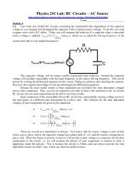
We will study the very simple circuit shown below. It is called the RC circuit:<br />
In this circuit, Q(0) is the initial amount of charge on each plate of the capacitor (+ or –). R is the<br />
resistance of the resistor in the circuit. C is the capacitance of the capacitor. In SI units, this is<br />
typically very small, i.e. 1x10 -6 Farads is quite large for normal circuitry. When the switch is thrown,<br />
the charge flows from one capacitor plate through the resistor to the other capacitor plate until the<br />
charges are completely neutralized.<br />
When you discharge a capacitor through the above circuit, the charge on each capacitor plate<br />
decays exponentially in time,<br />
Q(t) = Q(0)e " t<br />
RC<br />
.<br />
Since you know that "V = Q , you can rewrite this equation by dividing both sides by C:<br />
C<br />
! V(t) = V(0)e " t<br />
RC<br />
.<br />
Incidentally, when you charge a capacitor, the charge accumulates on the plates with<br />
!<br />
#<br />
Q(t) = Q MAX<br />
1" e " t &<br />
#<br />
RC<br />
% ( or alternativelyV(t) = V APPLIED<br />
1" e " t &<br />
RC<br />
% (.<br />
$ ! '<br />
$ '<br />
In other words, you must apply the voltage long enough to charge Q MAX on the capacitor plate.<br />
!<br />
!<br />
1
Write your answers directly onto these pages and be sure to hand them in for credit with your<br />
report!<br />
Lab 7 – Theory Worksheet – <strong>Differential</strong> <strong>Equations</strong> – Together<br />
1. Can you use a math model? Suppose I told you that the equation describing the time<br />
dependence of the electric potential difference across a capacitor in a circuit was<br />
"V (t) = "V (0)e # t $<br />
.<br />
Now imagine that you measured "V (0) = 3 volts and "V (10 seconds) =1 volt . Calculate the<br />
time constant τ. You will see later in this activity that " = RC, and since you can measure R and<br />
calculate τ, you can find that capacitance of the capacitor, C.<br />
!<br />
[Your work]:<br />
!<br />
!<br />
2. In what follows, we will derive a differential equation to model an RC circuit. Then we will<br />
solve it. I cannot stress the importance of these two steps. Most physicists make their living by<br />
• Creating a differential equation to model reality, and<br />
• Solving the differential equation to make predictions about reality.<br />
Really, that is pretty much what we do!<br />
2
Construction of the differential equation (the physics). When you go hiking on a mountain and<br />
return to your starting location, you will have a net change in height of zero, "( height) = 0. By<br />
analogy, when you add up the change in electric potential around an RC circuit and end where<br />
you began, you should find that "V = 0.<br />
0 = "V resistor<br />
+"V capacitor<br />
.<br />
!<br />
You can then use Ohm’s law for the resistor and the definition of capacitance to get:<br />
! 0 = RI + Q(t) capacitor<br />
.<br />
C<br />
!<br />
Now, what is the current through the resistor? It is the charge per time passing through<br />
the resistor. So we can write<br />
! 0 = R dQ(t) Resistor<br />
+ Q(t) capacitor<br />
.<br />
dt C<br />
Since the charges that flow onto or off of the capacitor plates must do so at the same<br />
rate as through the resistor (or they will bunch up inside the resistor - nonsensical) we can<br />
assume that<br />
dQ(t) Resistor<br />
dt<br />
! = dQ(t) Capacitor<br />
dt<br />
so that we have<br />
0 = R dQ(t) capacitor<br />
+ Q(t) capacitor<br />
.<br />
dt C<br />
!<br />
This is a differential equation, an equation that contains derivatives!<br />
a. What is the independent variable in this equation?<br />
!<br />
b. What is the dependent variable?<br />
c. If the solution to an algebraic equation is one or more points, what is the solution to a<br />
differential equation supposed to be?<br />
d. What is the highest order time derivative in this equation? So how many functionsolutions<br />
will we have? (Compare to linear and quadratic algebraic equations.)<br />
3
Restating the differential equation:<br />
0 = R dQ(t)<br />
dt<br />
+ Q(t)<br />
C<br />
3. Solving the differential equation to find Q(t) (the math).<br />
We have two physical situations in our lab experiments today, charging and discharging<br />
the capacitor. We will only examine discharging<br />
!<br />
the capacitor because the math is pretty much<br />
the same.<br />
Discharging the capacitor occurs when you close the switch and let charges flow.<br />
Rearranging the differential equation a little bit gives:<br />
0 = dQ(t) + Q(t) dQ(t)<br />
or rather<br />
= - Q(t)<br />
RC<br />
dt RC dt<br />
The best method for solving differential equations is guessing. We want a function Q(t)<br />
such that when you take its time derivative, you get the same function back with a negative<br />
1/RC. A function that has this property is an exponential function.<br />
!<br />
i. Allow me to guess the function-solution for you: Q(t) = e " t<br />
RC<br />
. Plug this guess solution into<br />
the differential equation and show that it is in fact a solution.<br />
[your work]<br />
!<br />
ii. What value does your equation give for Q(0) at the beginning of the discharge?<br />
4
Restating the discharging differential equation:<br />
dQ(t)<br />
dt<br />
= - Q(t)<br />
RC<br />
iii. What if your capacitor had an initial charge, Q(0), that did not equal 1? Try the solution<br />
Q(t) = Q(0)e " t<br />
RC<br />
and check that<br />
!<br />
1. it gives the correct initial value, and<br />
!<br />
2. it still satisfies the differential equation.<br />
This step of solving differential equations is called taking account of the boundary<br />
conditions.<br />
iv. Make a quick and tiny sketch of this solution, Q(t) vs. t.<br />
v. What do you get for<br />
Lim<br />
t "#<br />
Q(t) and does this make sense?<br />
!<br />
vi. Does discharging the capacitor occur faster or slower if you increase the capacitance of the<br />
capacitor. Use your graphing calculator to find out!<br />
vii. Does discharging the capacitor occur faster or slower if you increase the resistance of the<br />
resistor. Use your graphing calculator to find out!<br />
5
Restating the solution in terms of voltage: V(t) = V(0)e " t<br />
RC<br />
.<br />
THIS IS THE EQUATION YOU WILL BE TESTING TODAY!<br />
Lab 7 – Together Section of Lab – reminder: your solutions on these pages are worth serious<br />
points today!<br />
1. Experiment 1: Measuring the RC circuit, V vs. t.<br />
a. Set your function generator to create a square wave with a voltage alternating between<br />
V MIN = 0 Volts and V MAX = 3 Volts with a frequency of 1,000 Hz. Do this by 1 st setting the<br />
frequency, then setting the wave to oscillate between +1.5 V and -1.5V, then use the DC<br />
offset to shift your signal to have V MIN = 0 Volts. What do you see on the oscilloscope?<br />
(YOU NEED TO USE LABELED AXIIS WITH LABELED HASH MARKS!!!)<br />
!<br />
b. Now set up an RC circuit with R=1 kΩ and C=0.1 µF in series with the same square wave<br />
from the previous question. Then answer the following questions.<br />
i. During the time interval that the square wave is at +3 Volts, is<br />
the capacitor being charged or discharged?<br />
ii. During the time interval that the square wave is at +0 Volts, is<br />
the capacitor being charged or discharged?<br />
iii. Which component must you measure to determine the total<br />
current of the circuit?<br />
iv. I want you to measure the voltage across the capacitor and the<br />
total circuit voltage simultaneously. Draw where you should put<br />
the oscilloscope leads on the circuit diagram shown above. Be sure to specify whether to use a<br />
bottom ground or middle ground setup.<br />
6
v. Perform the measurement described in part d and record your observations (LABELS/UNITS):<br />
vi. Explain in detail what is physically happening so that you see shark fins in the above circuit.<br />
vii. What do you see when you increase the square wave frequency to higher and higher values?<br />
What physically causes this?<br />
7
Lab 7 – Final comments before you start working on your own.<br />
• Only charge electrolytic capacitors in the correct direction! Here let me show you…<br />
Lab 7 – Procedure – On your own.<br />
Experiment 2: Big capacitance = slow decay: DMM measurements of discharge only.<br />
• Create an RC circuit with R=47kΩ and C=1000µF (electrolytic). Charge an electrolytic<br />
capacitor without resistance (fast) in the correct direction and then switch to discharge through<br />
a resistor (bypassing the voltage supply).<br />
• Use a stopwatch to make voltage measurements across the capacitor as a function of time.<br />
Collect more data initially as the capacitor discharges more rapidly. Collect data until you<br />
reach ¼ of your initial starting voltage. This process should take a little more than one minute.<br />
1. Construct a graph of the capacitor discharging: capacitor voltage vs. time.<br />
2. Does your graph seem to behave as your theoretically predicted relationship using the<br />
function solution to a differential equation (1 complete sentence explanation)?<br />
GRAPH 1<br />
3. Use your graph to find how long it takes to drop from peak voltage to half this value.<br />
This is the half-life of the circuit. What is the half-life in seconds? Compare this to the<br />
product of R and C. (Check your answers with me!)<br />
1. Measured half life = ______________seconds<br />
2. R*C = _____________ seconds<br />
3. Mathematically, what should R*C represent?<br />
ANS: The time is takes for the voltage to fall to ____ of its initial value.<br />
4. Use your graph to find how long it takes to drop from one half-peak voltage to one<br />
quarter peak voltage (another halving step). This is another half-life of the circuit and<br />
should be about the same as in #2. Get me if the second half-life time is not about the<br />
same as the first.<br />
5. The fact that each halving of the decaying voltage occurs in the same amount of time is<br />
a unique property of what mathematical function?<br />
8
6. Make a graph of ln(V(t)) vs. t. This should give you a straight line. The slope of this<br />
line is -1/RC. Use this slope to calculate R*C. Get me if your value is not close to the<br />
value of RC using the labeled values. GRAPH 2.<br />
7. In the previous graph, I claimed that the slope was -1/RC. Why mathematically is this<br />
true?<br />
8. Imagine that you are a biologist modeling exponential population growth with<br />
P(t) = P(0)e rt . If you had a database containing population versus time data, how<br />
would you determine the population growth rate, r?<br />
!<br />
9. Why are seconds the units of R*C?<br />
Experiment 3: Little capacitance (rapid charging and discharging measured on an oscilloscope).<br />
1. Construct the same RC circuit as in experiment 1: R = 1 kΩ, C = 0.1 µF, square wave with<br />
V MIN = 0 V & V MAX = 3 V and frequency of 1,000 Hz.<br />
2. Measure the half-life of this rapidly decaying RC circuit. Be sure to stretch and maneuver your<br />
oscilloscope screen to make an accurate measurement. This value should be in the<br />
microsecond range or you are making an error. (Remember how to use SECONDS/DIV!!!)<br />
T 1/2 reported = _____________ seconds.<br />
3. Use your DMM to obtain and accurate value for R. Then use this value and the half-life to<br />
calculate C, the capacitance of the tiny capacitor. Use the same math procedure we first<br />
practiced on page 2, Theory Worksheet #1.<br />
4. CLEAN UP LAB STATION.<br />
C reported = _____________ Farads.<br />
9
Lab 7 – Report Guidelines<br />
I will be paying careful attention to your solutions in the above pages. These solutions will<br />
be worth approximately one third of your lab report points this week. (Ellipsis means you should not<br />
need help here on what to write about).<br />
1. Title - …<br />
2. Goals – Something about differential equations and RC circuits.<br />
3. Theory –<br />
• What is the discharging differential equation? What physics principles did we use to<br />
create this differential equation: name at least 3 (do not derive the equation or its<br />
solution, we did that together already)?<br />
• How did we solve the discharging differential equation and what was our solution?<br />
What kind of functional decay do you find when discharging a capacitor?<br />
4. Procedure – No more than 3 sentences for each experiment please!!!<br />
5. Results<br />
NO TYPING TODAY. YOUR RESULTS ARE YOUR TWO VERY NEATLY<br />
MADE GRAPHS FOR THE LARGE DISCHARGING CAPACITOR (EXPERIMENT<br />
2) AND ALL YOUR PAGES OF NOTES/SOLUTIONS. <br />
6. PROBLEMS – YOU ALREADY DID THEM ON THESE HERE PAGES!!! <br />
7. Conclusion –<br />
a. Describe how an RC circuit works, and how you proved this experimentally by testing<br />
with both a large RC and a small RC. (~ 2 sentences)<br />
b. Explain how your lab today had you perform a complete physics research project (~3<br />
sentences total):<br />
1. Model some feature of the universe with a differential equation.<br />
2. Solve the differential equation to find some particular behavior of the<br />
universe.<br />
3. Experimentally verify that your mathematical model correctly describes<br />
this aspect of the universe (this is the part the Aristotle messed up).<br />
c. As a last optional paragraph, discuss if you believe physics can tell us about reality or<br />
merely models reality. (But not too long.) Note: I will keep my opinions to myself to<br />
stay out of trouble!<br />
d. As a last optional paragraph, explain how I might make this lab simpler in the future<br />
without giving up academic content. Or do you like it the way it is? (Honest feedback<br />
only, please.)<br />
8. Attachments including all the notes you took on the pages of this handout.<br />
10