Alternating Current in RC Circuits
Alternating Current in RC Circuits
Alternating Current in RC Circuits

Create successful ePaper yourself
Turn your PDF publications into a flip-book with our unique Google optimized e-Paper software.
Physics 241 Lab – Matt Leone<br />
Week 8: <strong>Alternat<strong>in</strong>g</strong> <strong>Current</strong> <strong>in</strong> <strong>RC</strong> <strong>Circuits</strong><br />
Leone@physics.arizona.edu (email preferred), PAS 376, o. 520-621-6819<br />
Office Hours: M & W 11:00-11:50, or by appo<strong>in</strong>tment. Consultation Room (PAS 372): F 12:00-12:50<br />
http://bohr.physics.arizona.edu/~leone/phy241/phys241lab.html<br />
General Comments:<br />
• Today we study ALTERNATING CURRENT charg<strong>in</strong>g and discharg<strong>in</strong>g of capacitors.<br />
• You will practice us<strong>in</strong>g your oscilloscope <strong>in</strong> a test-like environment.<br />
Lab 8 – Summary:<br />
There are three key concepts you should know about an <strong>RC</strong> circuit driven with a s<strong>in</strong>e source.<br />
1. The capacitor voltage lags beh<strong>in</strong>d the resistor voltage by 90 o (phase shift).<br />
2. The capacitor is described by a capacitive reactance X C that acts like a resistance.<br />
3. A s<strong>in</strong>usoidally driven circuit is described by an overall IMPEDANCE, Z that acts<br />
like the total resistance of the whole circuit.<br />
Lab 8 – Matt’s discussion on board: now on the paper!<br />
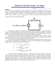
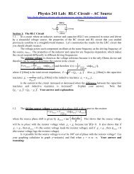
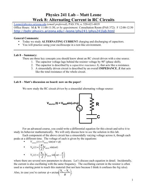
We now study the <strong>RC</strong> circuit driven by a s<strong>in</strong>usoidal alternat<strong>in</strong>g voltage source:<br />
For an advanced course, you could write a differential equation for this circuit and solve it to<br />
study its behavior mathematically. We will only discuss how to use the solution <strong>in</strong> this lab.<br />
Each component of the above circuit has a s<strong>in</strong>usoidally vary<strong>in</strong>g voltage across it, though each<br />
peaks at a different time. The voltage of each is given by the equations:<br />
• V source<br />
(t) = V MAX<br />
s<strong>in</strong>("t + #)<br />
"<br />
• V R<br />
(t) = R %<br />
$ ' V<br />
# Z &<br />
MAX<br />
s<strong>in</strong>((t)<br />
!<br />
#<br />
• V C<br />
(t) = " &<br />
C<br />
%<br />
$ Z '<br />
( V s<strong>in</strong> #<br />
)t * + &<br />
%<br />
MAX $ 2 (<br />
'<br />
where ! there are several new parameters to discuss. Let’s discuss each equation <strong>in</strong> detail. Incidentally,<br />
the current is also oscillat<strong>in</strong>g with the same frequency. The oscillat<strong>in</strong>g current <strong>in</strong> the resistor is often<br />
used as a start<strong>in</strong>g po<strong>in</strong>t to teach $ this material (but not here because I th<strong>in</strong>k it confuses the big idea).<br />
!<br />
%<br />
Also, <strong>in</strong> case you’re curious " = arctan # L<br />
$ # C<br />
(<br />
' *.<br />
& R )<br />
!<br />
1
!<br />
V source<br />
(t) = V MAX<br />
s<strong>in</strong>("t + #)<br />
The source voltage equation is straightforward. It oscillates s<strong>in</strong>usoidally, i.e. it is a s<strong>in</strong>e<br />
function of time. It determ<strong>in</strong>es the maximum voltage across the whole circuit with V MAX . It oscillates<br />
with an angular frequency " = 2#f .<br />
Notice that it also has a phase shift φ. Now why on earth would we describe the source voltage<br />
with a phase shift? If you look below at the resistor equation, you will see no phase shift. What this<br />
means is that we measure all phases <strong>in</strong> relation to the resistor not the source. The resistor will have<br />
its maximum voltage<br />
!<br />
at a different time than when the source voltage is maximum.<br />
!<br />
"<br />
V R<br />
(t) = R %<br />
$ ' V<br />
# Z &<br />
MAX<br />
s<strong>in</strong>((t)<br />
The resistor voltage equation <strong>in</strong>cludes some new stuff. It also oscillates s<strong>in</strong>usoidally and<br />
without a phase shift. R is the resistance.<br />
What is new is Z. Z is the impedance of the whole circuit. It is given by the equation<br />
( ) 2 .<br />
Z = R 2 + " L<br />
# " C<br />
Uh oh, this def<strong>in</strong>ition has new stuff, too. Now X L and X C are like the resistances of the <strong>in</strong>ductor and<br />
capacitor <strong>in</strong> the circuit. S<strong>in</strong>ce we don’t have an <strong>in</strong>ductor (coil) <strong>in</strong> the circuit, you can set this to zero.<br />
So we have Z = R 2 + " 2 C<br />
.<br />
!<br />
Now what if I rewrote the resistor equation as V R<br />
(t) = V R,MAX<br />
s<strong>in</strong>("t). What maximum and<br />
m<strong>in</strong>imum voltage would oscillate across the resistor? V R,MAX<br />
= R<br />
!<br />
Z V MAX<br />
. That means that the ratio of<br />
the resistor resistance and the total circuit resistance (impedance) times the source amplitude gives you<br />
the amplitude of the voltage just across the resistor.<br />
!<br />
!<br />
#<br />
V C<br />
(t) = " &<br />
C<br />
%<br />
$ Z '<br />
( V s<strong>in</strong> #<br />
)t * + &<br />
%<br />
MAX $ 2 (<br />
'<br />
!<br />
The capacitor voltage oscillates s<strong>in</strong>usoidally and lags the voltage across the resistor by 90 o .<br />
$<br />
Knowledge of trigonometry allows you to also write V C<br />
(t) = " # '<br />
C<br />
& ) V<br />
% Z (<br />
MAX<br />
cos (*t) s<strong>in</strong>ce s<strong>in</strong>e shifted left<br />
by 90 o is the negative cos<strong>in</strong>e. This is sometimes useful for graph<strong>in</strong>g.<br />
The reactive capacitance is like the resistance of the capacitor. More precisely, " C<br />
= 1<br />
#C .<br />
!<br />
Yikes! The “resistance” of the capacitor is related to the capacitance of the capacitor. The larger the<br />
capacitance, the less “resistance” <strong>in</strong> the capacitor. But just as importantly X C is also related to the<br />
frequency of the driv<strong>in</strong>g voltage. If the frequency is <strong>in</strong>creased, the “resistance” of the capacitor<br />
decreases. This is why a capacitor is often used as a high pass filter. The capacitor ! has less resistance<br />
to more quickly oscillat<strong>in</strong>g currents. BE SURE TO REMEMBER THIS DURING TODAY’S LAB!<br />
%<br />
Now what if I rewrote the capacitor equation as V C<br />
(t) = V C,MAX<br />
s<strong>in</strong> "t # $ (<br />
' *. What maximum<br />
& 2 )<br />
and m<strong>in</strong>imum voltage would oscillate across the capacitor? V C,MAX<br />
= " C<br />
Z V MAX<br />
. That means that the<br />
ratio of the capacitive reactance and the total circuit resistance (impedance) times the source amplitude<br />
gives you the amplitude of the voltage just across<br />
!<br />
the capacitor.<br />
!<br />
2
Lab 8 – Predictions – rem<strong>in</strong>der: your solutions on these pages are always worth po<strong>in</strong>ts.<br />
!<br />
Lets work though an example before we beg<strong>in</strong>. Remember the equations,<br />
V source<br />
(t) = V MAX<br />
s<strong>in</strong>("t + #)<br />
"<br />
V R<br />
(t) = R %<br />
#<br />
$ ' V<br />
# Z &<br />
MAX<br />
s<strong>in</strong>((t) V C<br />
(t) = " &<br />
C<br />
%<br />
$ Z '<br />
#<br />
)t * + &<br />
%<br />
MAX $ 2 (<br />
'<br />
If your circuit has V MAX<br />
= 2 Volts, R =10,000 " , C =1x10 -7 Farads, and " =1,500 radians/sec f<strong>in</strong>d<br />
the follow<strong>in</strong>g values with correct units<br />
1. X C .<br />
!<br />
!<br />
!<br />
!<br />
!<br />
!<br />
2. Z<br />
3. V R,MAX .<br />
4. V C,MAX .<br />
5. Now exam<strong>in</strong>e V R,MAX + V C,MAX .<br />
They add to more than V MAX !!! No, you didn’t make a mistake. S<strong>in</strong>ce the voltages are out of phase,<br />
their maximums do not add together at the same time. Now let’s visualize this.<br />
6. Write the functions for V R<br />
(t) and<br />
V C<br />
(t).<br />
7. Plot V R<br />
(t) and V C<br />
(t) on the o-scope screen below. Be sure to label units and hash marks<br />
! !<br />
correctly for full credit.<br />
!<br />
!<br />
8. On your graph, sketch the addition of the V R<br />
(t) and V C<br />
(t). This is V source<br />
(t).<br />
3<br />
!<br />
!<br />
!
Lab 8 – On your own.<br />
Experiment 1: Exam<strong>in</strong><strong>in</strong>g the phase shift between V R<br />
(t) and<br />
V C<br />
(t).<br />
a. Set your function generator to create a s<strong>in</strong> wave with a voltage amplitude of a nice round<br />
number like 3 Volts. You may change your frequency later, but start at about 400 Hz..<br />
! !<br />
b. Set up the <strong>RC</strong> circuit with the s<strong>in</strong>usoidal driv<strong>in</strong>g function generator with R =10,000 " ,<br />
and C =1x10 -7 Farads.<br />
c. Set up a middle ground to view the voltage across both the resistor and the capacitor<br />
simultaneously. Make a sketch on the o-scope screen below mak<strong>in</strong>g<br />
!<br />
sure to <strong>in</strong>vert the<br />
!<br />
correct channel for your graph (a necessary step when us<strong>in</strong>g a middle ground).<br />
!<br />
d. Label the signals V R<br />
(t) and V C<br />
(t) on your sketch and determ<strong>in</strong>e equations for V R<br />
(t) and<br />
V C<br />
(t). Also expla<strong>in</strong> which is phase shifted by 90 o . Write your equations and<br />
explanation here:<br />
!<br />
!<br />
!<br />
4
Experiment 2: Test<strong>in</strong>g the relationship " C<br />
= 1 with many frequencies.<br />
#C<br />
a. Use the theoretical relationship " C<br />
= 1 and the equations for voltage amplitutde on the resistor<br />
#C<br />
and capacitor, V C,MAX<br />
= " C<br />
!<br />
Z V and<br />
MAX<br />
V R,MAX<br />
= R Z V MAX<br />
to calculate the driv<strong>in</strong>g angular frequency<br />
necessary to have V R,MAX<br />
= V<br />
! C,MAX<br />
. (You will want to take your data around this angular<br />
frequency <strong>in</strong> the next parts of this experiment.) Report ω EQUAL here.<br />
!<br />
!<br />
!<br />
b. Set your function generator to create a s<strong>in</strong> wave with a voltage amplitude of a nice round number<br />
like 3 Volts. You will be adjust<strong>in</strong>g the frequency dur<strong>in</strong>g the experiment. Use the same R and C<br />
as <strong>in</strong> experiment 1.<br />
c. S<strong>in</strong>ce<br />
!<br />
V C,MAX<br />
= " C<br />
Z V MAX and<br />
V C,MAX<br />
V R,MAX<br />
= R Z V MAX<br />
, divid<strong>in</strong>g these equations gives<br />
= " C<br />
or after multiply<strong>in</strong>g both sides by R, " C<br />
= R #V C,MAX<br />
.<br />
V R,MAX<br />
R V R,MAX<br />
You can measure V!<br />
C,MAX<br />
and V R,MAX<br />
on the oscilloscope, and you can measure R with a DMM.<br />
Therefore, f<strong>in</strong>d X C for many different frequencies us<strong>in</strong>g the equation <strong>in</strong> the box above.<br />
Remember that you can only be sure a DMM resistance measurement<br />
!<br />
!<br />
is accurate by measur<strong>in</strong>g<br />
the resistor naked. Use the data table below:<br />
! !<br />
d. Plot X C vs. ω to support our claim that there is an <strong>in</strong>verse relationship between them. Be sure to<br />
f<strong>in</strong>d ω from f before graph<strong>in</strong>g. (Th<strong>in</strong>k about what the graph should look like if " C<br />
= 1<br />
#C ?)<br />
GRAPH 1<br />
e. Expla<strong>in</strong> why your graph supports the relationship " C<br />
= 1 . Write explanation ! here:<br />
#C<br />
!<br />
5
Experiment 3: F<strong>in</strong>d<strong>in</strong>g C with a s<strong>in</strong>gle frequency measurement.<br />
a. Us<strong>in</strong>g the relationship from experiment 2,<br />
" C<br />
= R #V C,MAX<br />
V R,MAX<br />
You can use this relation for experimental determ<strong>in</strong>ations of C.<br />
1<br />
, you know that<br />
"C = R # V C,MAX<br />
V R,MAX .<br />
b. Make a s<strong>in</strong>gle measurement of ω, ! R, V R,MAX and V C,MAX us<strong>in</strong>g a ! frequency where V R,MAX<br />
and V C,MAX are about the same and determ<strong>in</strong>e C. Report your value for C here:<br />
c. Now perform an x-y measurement with the oscilloscope for V R<br />
(t) versus<br />
ω EQUAL and sketch your result on scope A. Be sure to label your axis.<br />
V C<br />
(t). Start with<br />
d. Now lower the frequency so that V C<br />
(t) is larger than V<br />
! R<br />
(t) and sketch your result on B<br />
!<br />
(another x-y measurement).<br />
e. Now raise the frequency so that V<br />
!<br />
C<br />
(t) is smaller than V<br />
!<br />
R<br />
(t) and sketch your result on C<br />
(another x-y measurement).<br />
A B C<br />
!<br />
!<br />
f. Expla<strong>in</strong> why V C<br />
(t) is larger than V R<br />
(t) when the frequency is low enough. Write<br />
explanation here:<br />
Experiment 4:<br />
!<br />
Mak<strong>in</strong>g and measur<strong>in</strong>g<br />
!<br />
your own capacitor.<br />
a. Make a capacitor from the square cardboard pieces covered <strong>in</strong> foil. Sandwich a non-foil<br />
square with them, and be sure your makeshift capacitor is not shorted.<br />
b. Measure the capacitance of your homemade capacitor us<strong>in</strong>g the technique from part 3. Be<br />
sure to f<strong>in</strong>d a frequency where V R,MAX and V C,MAX are about the same. You may need to<br />
use a different resistor. Report your homemade capacitor capacitance here:<br />
5. CLEAN UP LAB STATION.<br />
6
Lab 8 – Report Guidel<strong>in</strong>es<br />
I will be pay<strong>in</strong>g careful attention to your solutions <strong>in</strong> the above pages. (Ellipsis means you<br />
should not need help here on what to write about).<br />
1. Title - …<br />
2. Goals – …<br />
3. Theory –<br />
• When an <strong>RC</strong> circuit is driven with a s<strong>in</strong>usoidal voltage source, how do the voltages<br />
across the resistor and capacitor behave? What functions describe them?<br />
• At any <strong>in</strong>stant of time, the voltage across the resistor plus the voltage across the<br />
capacitor should add to the voltage across the source. Sometimes the voltage across the<br />
source is zero s<strong>in</strong>ce it is alternat<strong>in</strong>g. At this particular <strong>in</strong>stant of time, what must happen<br />
with the voltages across the resistor and capacitor?<br />
4. Procedure – No more than 3 sentences for each experiment please!!!<br />
5. Results – Describe your results for each experiment with a separate short paragraph.<br />
6. Conclusion – Write a short conclusion paragraph for each experiment and a f<strong>in</strong>al summariz<strong>in</strong>g<br />
paragraph.<br />
7. Attachments <strong>in</strong>clud<strong>in</strong>g all the notes you took on the pages of this handout.<br />
7