Zigbee board datasheet EB051-00-1 - Matrix Multimedia Ltd
Zigbee board datasheet EB051-00-1 - Matrix Multimedia Ltd
Zigbee board datasheet EB051-00-1 - Matrix Multimedia Ltd

You also want an ePaper? Increase the reach of your titles
YUMPU automatically turns print PDFs into web optimized ePapers that Google loves.
E-blocks <strong>Zigbee</strong> <strong>board</strong><br />
Document code: <strong>EB051</strong>-30-1<br />
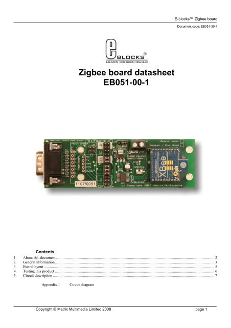
<strong>Zigbee</strong> <strong>board</strong> <strong>datasheet</strong><br />
<strong>EB051</strong>-<strong>00</strong>-1<br />
Contents<br />
1. About this document.................................................................................................................................................................. 2<br />
2. General information................................................................................................................................................................... 3<br />
3. Board layout .............................................................................................................................................................................. 5<br />
4. Testing this product ................................................................................................................................................................... 6<br />
5. Circuit description ..................................................................................................................................................................... 7<br />
Appendix 1<br />
Circuit diagram<br />
Copyright © <strong>Matrix</strong> <strong>Multimedia</strong> Limited 2<strong>00</strong>8 page 1
E-blocks <strong>Zigbee</strong> <strong>board</strong><br />
Document code: <strong>EB051</strong>-30-1<br />
1. About this document<br />
This document concerns the E-blocks <strong>Zigbee</strong> <strong>board</strong>s with codes <strong>EB051</strong>C and <strong>EB051</strong>R version 1.<br />
The order code for the <strong>Zigbee</strong> Coordinator product is <strong>EB051</strong>C.<br />
The order code for the <strong>Zigbee</strong> Router / End Device product is <strong>EB051</strong>R.<br />
1. Trademarks and copyright<br />
PIC and PICmicro are registered trademarks of Arizona Microchip Inc.<br />
E-blocks is a trademark of <strong>Matrix</strong> <strong>Multimedia</strong> Limited.<br />
2. Other sources of information<br />
There are various other documents and sources that you may find useful:<br />
Getting started with E-Blocks.pdf EB355<br />
This describes the E-blocks system and how it can be used to develop complete systems for learning electronics and<br />
for PICmicro programming.<br />
3. Disclaimer<br />
The information in this document is correct at the time of going to press. <strong>Matrix</strong> <strong>Multimedia</strong> reserves the right to<br />
change specifications from time to time. This product is for development purposes only and should not be used for<br />
any life-critical application.<br />
4. Technical support<br />
If you have any problems operating this product then please refer to the testing section of this document first. You<br />
will find the latest software updates, FAQs and other information on our web site: www.matrixmultimedia.com . If<br />
you still have problems please email us at: support@matrixmultimedia.co.uk.<br />
Copyright © <strong>Matrix</strong> <strong>Multimedia</strong> Limited 2<strong>00</strong>8 page 2
E-blocks <strong>Zigbee</strong> <strong>board</strong><br />
Document code: <strong>EB051</strong>-30-1<br />
2. General information<br />
1. Description<br />
Provides a <strong>Zigbee</strong> node interface that can connect to or create a <strong>Zigbee</strong> network.<br />
<strong>EB051</strong>C – Coordinator <strong>Zigbee</strong> node, used to start, configure the network and allow other nodes to join.<br />
<strong>EB051</strong>R – Router / End device node, used to connect and communicate to networks started by a <strong>EB051</strong>C.<br />
<strong>Zigbee</strong> is a software-based protocol that sits on top of the 802.11 RF wireless devices standard similar to Bluetooth.<br />
Unlike Bluetooth, <strong>Zigbee</strong> is capable of forming large networks of nodes and boasts advanced features such as mesh<br />
networking, simple addressing structures, route detection, route repair, guaranteed delivery and low power operation<br />
modes.<br />
The <strong>EB051</strong> <strong>Zigbee</strong> E-Blocks are fully compliant with both the <strong>Zigbee</strong> pro (07) and ZNET (08) <strong>Zigbee</strong> standards.<br />
The <strong>board</strong>s can be used create a network of dynamic moveable <strong>Zigbee</strong> nodes, or to interface with an existing <strong>Zigbee</strong><br />
network.<br />
<strong>Zigbee</strong> provides a transparent layer for sending and receiving data from the network. Therefore once the module has<br />
been configured and assigned to the correct address then sending and receiving data is as simple as sending and<br />
receiving RS232 bytes through the chip’s UART.<br />
2. Features<br />
• <strong>Zigbee</strong> Wireless communications<br />
• Flowcode macros available<br />
• Compatible with global RF standards<br />
• On<strong>board</strong> <strong>Zigbee</strong> module<br />
• Status LED<br />
• Full 2<strong>00</strong>7 <strong>Zigbee</strong> Pro / ZNET compliance<br />
• 128-bit AES Encryption<br />
• Range of approx 1<strong>00</strong>m per node<br />
3. <strong>Zigbee</strong> Operation<br />
The <strong>Zigbee</strong> <strong>board</strong>s use a V2 XBEE module to interface to the <strong>Zigbee</strong> network. These modules are compliant with<br />
the 2<strong>00</strong>7 <strong>Zigbee</strong> Pro / ZNET standard.<br />
The V2 XBEE modules come in two varieties. One is configured to be the <strong>Zigbee</strong> network coordinator (<strong>EB051</strong>C)<br />
and the other is configured to be either a router node or an end device node (<strong>EB051</strong>R). The variety of the module is<br />
marked at the top right hand side of the <strong>Zigbee</strong> <strong>board</strong>.<br />
• Coordinator nodes are responsible for creating the <strong>Zigbee</strong> network and allowing other <strong>Zigbee</strong> nodes to join.<br />
Only one coordinator node can exist on any single network.<br />
• Router nodes are responsible for routing signals to other routers or to end nodes.<br />
• End device nodes are responsible for collecting or depositing real world data to and from the <strong>Zigbee</strong><br />
network.<br />
The Coordinator node and Router nodes are capable of handling up to eight children devices. The children devices<br />
can consist of either other Router nodes or End device nodes. If an End device node is configured to sleep then the<br />
parent device associated for that node will be responsible for buffering any incoming data. Therefore if you are<br />
using sleeping End devices you must make sure to poll the parent for data every time the device comes out of sleep<br />
mode.<br />
Copyright © <strong>Matrix</strong> <strong>Multimedia</strong> Limited 2<strong>00</strong>8 page 3
E-blocks <strong>Zigbee</strong> <strong>board</strong><br />
Document code: <strong>EB051</strong>-30-1<br />
4. 3.3V system compatibility<br />
The <strong>board</strong> is compatible with 3.3V and 5V systems.<br />
5. Communications<br />
The XBEE modules are configured by means of using a TTL level RS232 bus to send and receive AT commands.<br />
This protocol requires a start bit, eight data bits and a stop bit.<br />
The baud rate for the XBEE modules is set to 96<strong>00</strong>, with no parity and flow control lines RTS and CTS that can be<br />
used. AT commands are strings of ASCII data that are sent over the RS232 bus. For more information on the AT<br />
commands used by the XBEE module please refer to the V2 XBEE <strong>datasheet</strong>.<br />
Example AT command<br />
ATID 234 - Assigns a personal area network identifier of 0x234 or 564 in decimal.<br />
6. V2 XBEE Module<br />
For further data regarding the XBEE module please visit the following link.<br />
www.matrixmultimedia.com/<strong>datasheet</strong>s/XBEEV2.pdf<br />
Copyright © <strong>Matrix</strong> <strong>Multimedia</strong> Limited 2<strong>00</strong>8 page 4
E-blocks <strong>Zigbee</strong> <strong>board</strong><br />
Document code: <strong>EB051</strong>-30-1<br />
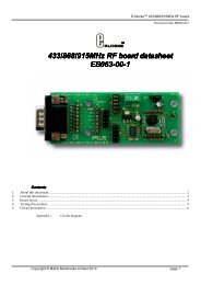
Board layout<br />
<strong>EB051</strong>-74-1.cdr<br />
1) 9 Way D-type Plug<br />
2) Patch system<br />
3) Rx and Tx UART routing selection<br />
4) CTS, RTS and SLEEP routing selection<br />
5) Input supply voltage select<br />
6) Input supply voltage screw terminals<br />
7) 3.3V regulator<br />
8) Voltage level shifter<br />
9) Status LED<br />
10) XBEE <strong>Zigbee</strong> module<br />
11) Coordinator / Router / End device marking.<br />
Copyright © <strong>Matrix</strong> <strong>Multimedia</strong> Limited 2<strong>00</strong>8 page 5
E-blocks <strong>Zigbee</strong> <strong>board</strong><br />
Document code: <strong>EB051</strong>-30-1<br />
3. Testing this product<br />
The following program will test the circuit <strong>board</strong>’s communication with the XBEE module. For further tests to test<br />
the XBEE modules RF operation you will require at least 1 <strong>EB051</strong>C and 1 or more <strong>EB051</strong>R <strong>Zigbee</strong> <strong>board</strong>s. The test<br />
file can be downloaded from www.matrixmultimedia.com.<br />
1. System Setup<br />
Multi-programmer <strong>board</strong> (EB<strong>00</strong>6) with:<br />
EB<strong>00</strong>6 Options<br />
Power supply<br />
PICmicro device<br />
SW1 (Fast/Slow)<br />
SW2 (RC/Xtal)<br />
Xtal frequency<br />
Port A<br />
Port B<br />
Port C<br />
Port D<br />
Port E<br />
Test program<br />
Setting<br />
External, 14V<br />
16F877A<br />
Don’t care<br />
Xtal<br />
19.6608MHz<br />
LCD <strong>board</strong> EB<strong>00</strong>5<br />
<strong>Zigbee</strong> <strong>board</strong> <strong>EB051</strong><br />
<strong>Zigbee</strong>.hex<br />
1 Ensure that the Multiprogrammer is in correct configuration<br />
- Fast mode (SW1 towards the center of the <strong>board</strong>)<br />
- XTAL mode (SW2 towards the center of the <strong>board</strong>)<br />
- Ensure that a 19.6608MHz crystal is inserted in the Multiprogrammer <strong>board</strong><br />
2 Insert the LCD <strong>board</strong> (EB-<strong>00</strong>5-<strong>00</strong>-1) into Port B of the Multiprogrammer<br />
3 Connect wire from “+V” of LCD <strong>board</strong> to “+V” of Multiprogrammer<br />
4 Program the a PIC16F877A with the test program <strong>Zigbee</strong>.hex<br />
5 Insert the <strong>Zigbee</strong> <strong>board</strong> into Port C of the Multiprogrammer<br />
6 Insert the XBEE module into the socket on the <strong>Zigbee</strong> <strong>board</strong><br />
7 Connect power to the <strong>Zigbee</strong> <strong>board</strong> via the “+V” screw terminals<br />
8 Make sure jumpers "C" and "1" are selected on the <strong>Zigbee</strong> <strong>board</strong>.<br />
9 Press the reset button on the Multiprogrammer.<br />
10 The word “Testing” should appear on the LCD screen.<br />
11 The LED in position D1 should start flashing.<br />
12 If the word OK appears on the LCD then testing is successful.<br />
13 Otherwise if an error message is displayed or the LED is not flashing then the test has failed.<br />
Copyright © <strong>Matrix</strong> <strong>Multimedia</strong> Limited 2<strong>00</strong>8 page 6
E-blocks <strong>Zigbee</strong> <strong>board</strong><br />
Document code: <strong>EB051</strong>-30-1<br />
4. Circuit description<br />
1. Description<br />
The circuit <strong>board</strong> consists of 5 digital I/O lines on a ‘downstream’ 9-way D-type plug. This routes the transmit<br />
(TX), receive (RX), clear to send (CTS), request to send (RTS) and sleep (SLEEP) lines to the XBEE <strong>Zigbee</strong><br />
module.<br />
Example of jumper settings C and 1, configured for use with a PIC16F877A.<br />
RX and TX jumper settings.<br />
Jumper Setting A Jumper Setting B Jumper Setting C Jumper Setting D<br />
PIC 16F Devices PIC 16C Devices<br />
PIC16F87 PIC16F627/A PIC16F73 PIC16C63 PATCH SYSTEM<br />
PIC16F88 PIC16F628/B PIC16F737 PIC16CR63<br />
PIC16F648A PIC16F74 PIC16C65/A/B<br />
PIC16F746 PIC16RC65<br />
PIC16F76<br />
PIC16C66<br />
PIC16F767 PIC16C73/A/B<br />
PIC16F77 PIC16C74/A/B<br />
PIC16F777 PIC16C745<br />
PIC16870/1 PIC16C765<br />
PIC16F873/A PIC16C77<br />
PIC16F874/A PIC16C773<br />
PIC16F876/A PIC16C774<br />
PIC16F877/A<br />
CTS, RTS and Sleep jumper settings.<br />
Jumper Setting 1 Jumper Setting 2<br />
RTS – Pin 0 PATCH SYSTEM<br />
CTS – Pin 4<br />
SLEEP – Pin 3<br />
Copyright © <strong>Matrix</strong> <strong>Multimedia</strong> Limited 2<strong>00</strong>8 page 7
Appendix 1 – Circuit diagram