ODU MINI-SNAP - PEI-FRANCE.com
ODU MINI-SNAP - PEI-FRANCE.com
ODU MINI-SNAP - PEI-FRANCE.com

You also want an ePaper? Increase the reach of your titles
YUMPU automatically turns print PDFs into web optimized ePapers that Google loves.
Catalogue<br />
Nr.: 1005-1-d-e<br />
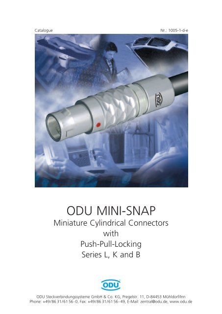
<strong>ODU</strong> <strong>MINI</strong>-<strong>SNAP</strong><br />
Miniature Cylindrical Connectors<br />
with<br />
Push-Pull-Locking<br />
Series L, K and B<br />
<strong>ODU</strong> Steckverbindungssysteme GmbH & Co. KG, Pregelstr. 11, D-84453 Mühldorf/Inn<br />
Phone: +49/86 31/61 56-0, Fax: +49/86 31/61 56- 49, E-Mail: zentral@odu.de, www.odu.de
The latest version of this catalogue<br />
is posted on our websites:<br />
www.odu.de<br />
www.odu-usa.<strong>com</strong><br />
www.odu-china.<strong>com</strong><br />
More Push-Pull series see page 137<br />
<strong>ODU</strong> <strong>MINI</strong>-<strong>SNAP</strong> is UL-listed under File E110586 00RT03566<br />
MIL-Specification: Tests carried out (See page 132).<br />
All data and specifications subject<br />
to change without notice.<br />
All dimensions in mm.<br />
All pictures are illustrations.
Table of Contents <strong>ODU</strong> <strong>MINI</strong>-<strong>SNAP</strong><br />
<strong>ODU</strong>-<strong>MINI</strong>-<strong>SNAP</strong> Product Description . . . . . . . . . . . . . . . . . . . . . . . . . . . . . . . . . . . . . . . . . . . . . . . . . . . . . . . . . . . 5<br />
Applications . . . . . . . . . . . . . . . . . . . . . . . . . . . . . . . . . . . . . . . . . . . . . . . . . . . . . . . . . . . . . . . . . . . . . . . . . . . . . . . . 7<br />
Important Issues At A Glance . . . . . . . . . . . . . . . . . . . . . . . . . . . . . . . . . . . . . . . . . . . . . . . . . . . . . . . . . . . . . . . . . . . 8<br />
Turned contact . . . . . . . . . . . . . . . . . . . . . . . . . . . . . . . . . . . . . . . . . . . . . . . . . . . . . . . . . . . . . . . . . . . . . . . . . . . . . . 9<br />
<strong>ODU</strong> <strong>MINI</strong>-<strong>SNAP</strong> Series L . . . . . . . . . . . . . . . . . . . . . . . . . . . . . . . . . . . . . . . . . . . . . . . . . . . . . . . . . . . . . . . . . . . 11<br />
-The LP Locking Concept . . . . . . . . . . . . . . . . . . . . . . . . . . . . . . . . . . . . . . . . . . . . . . . . . . . . . . . . . . . . . . . . . . . . . 12<br />
-Sizes . . . . . . . . . . . . . . . . . . . . . . . . . . . . . . . . . . . . . . . . . . . . . . . . . . . . . . . . . . . . . . . . . . . . . . . . . . . . . . . . . . . 14<br />
-Part Number Key (see also cover) . . . . . . . . . . . . . . . . . . . . . . . . . . . . . . . . . . . . . . . . . . . . . . . . . . . . . . . . . . . . 15<br />
-Housings . . . . . . . . . . . . . . . . . . . . . . . . . . . . . . . . . . . . . . . . . . . . . . . . . . . . . . . . . . . . . . . . . . . . . . . . . . . . . . . . 16<br />
-Keyings, Housing Materials/Surfaces, Collet System, Bend Protection Sleeves . . . . . . . . . . . . . . . . . . . . . . . . . . . . 29<br />
<strong>ODU</strong> <strong>MINI</strong>-<strong>SNAP</strong> Series K . . . . . . . . . . . . . . . . . . . . . . . . . . . . . . . . . . . . . . . . . . . . . . . . . . . . . . . . . . . . . . . . . . . 35<br />
-The LP Locking Concept . . . . . . . . . . . . . . . . . . . . . . . . . . . . . . . . . . . . . . . . . . . . . . . . . . . . . . . . . . . . . . . . . . . . . 36<br />
-Sizes . . . . . . . . . . . . . . . . . . . . . . . . . . . . . . . . . . . . . . . . . . . . . . . . . . . . . . . . . . . . . . . . . . . . . . . . . . . . . . . . . . . 38<br />
-Part Number Key (see also cover) . . . . . . . . . . . . . . . . . . . . . . . . . . . . . . . . . . . . . . . . . . . . . . . . . . . . . . . . . . . . 39<br />
-Housings . . . . . . . . . . . . . . . . . . . . . . . . . . . . . . . . . . . . . . . . . . . . . . . . . . . . . . . . . . . . . . . . . . . . . . . . . . . . . . . . 40<br />
-Keyings, Housing Materials/Surfaces, Collet System, Bend Protection Sleeves . . . . . . . . . . . . . . . . . . . . . . . . . . . . 49<br />
<strong>ODU</strong> <strong>MINI</strong>-<strong>SNAP</strong> Series B . . . . . . . . . . . . . . . . . . . . . . . . . . . . . . . . . . . . . . . . . . . . . . . . . . . . . . . . . . . . . . . . . . . 53<br />
-The FP Locking Concept . . . . . . . . . . . . . . . . . . . . . . . . . . . . . . . . . . . . . . . . . . . . . . . . . . . . . . . . . . . . . . . . . . . . . 54<br />
-Sizes . . . . . . . . . . . . . . . . . . . . . . . . . . . . . . . . . . . . . . . . . . . . . . . . . . . . . . . . . . . . . . . . . . . . . . . . . . . . . . . . . . . 56<br />
-Part Number Key (see also cover) . . . . . . . . . . . . . . . . . . . . . . . . . . . . . . . . . . . . . . . . . . . . . . . . . . . . . . . . . . . . 57<br />
-Housings . . . . . . . . . . . . . . . . . . . . . . . . . . . . . . . . . . . . . . . . . . . . . . . . . . . . . . . . . . . . . . . . . . . . . . . . . . . . . . . . 58<br />
-Keyings, Housing Materials/Surfaces, Collet System, Bend Protection Sleeves . . . . . . . . . . . . . . . . . . . . . . . . . . . . 65<br />
Inserts Series L, K, B . . . . . . . . . . . . . . . . . . . . . . . . . . . . . . . . . . . . . . . . . . . . . . . . . . . . . . . . . . . . . . . . . . . . . . . . 71<br />
Insulation Body Material . . . . . . . . . . . . . . . . . . . . . . . . . . . . . . . . . . . . . . . . . . . . . . . . . . . . . . . . . . . . . . . . . . . . . . 72<br />
Size 00 . . . . . . . . . . . . . . . . . . . . . . . . . . . . . . . . . . . . . . . . . . . . . . . . . . . . . . . . . . . . . . . . . . . . . . . . . . . . . . . . . . . 73<br />
Size 0 . . . . . . . . . . . . . . . . . . . . . . . . . . . . . . . . . . . . . . . . . . . . . . . . . . . . . . . . . . . . . . . . . . . . . . . . . . . . . . . . . . . . 74<br />
Size 1 . . . . . . . . . . . . . . . . . . . . . . . . . . . . . . . . . . . . . . . . . . . . . . . . . . . . . . . . . . . . . . . . . . . . . . . . . . . . . . . . . . . . 75<br />
Size 2 . . . . . . . . . . . . . . . . . . . . . . . . . . . . . . . . . . . . . . . . . . . . . . . . . . . . . . . . . . . . . . . . . . . . . . . . . . . . . . . . . . . . 76<br />
Size 3 . . . . . . . . . . . . . . . . . . . . . . . . . . . . . . . . . . . . . . . . . . . . . . . . . . . . . . . . . . . . . . . . . . . . . . . . . . . . . . . . . . . . 78<br />
Size 3 and Size 4 . . . . . . . . . . . . . . . . . . . . . . . . . . . . . . . . . . . . . . . . . . . . . . . . . . . . . . . . . . . . . . . . . . . . . . . . . . . . 79<br />
Size 5 and Size 6 . . . . . . . . . . . . . . . . . . . . . . . . . . . . . . . . . . . . . . . . . . . . . . . . . . . . . . . . . . . . . . . . . . . . . . . . . . . . 80<br />
Contact Type / Contact Surface-Contact Diameter . . . . . . . . . . . . . . . . . . . . . . . . . . . . . . . . . . . . . . . . . . . . . . . . . . 81<br />
Contact Termination Cross Sections . . . . . . . . . . . . . . . . . . . . . . . . . . . . . . . . . . . . . . . . . . . . . . . . . . . . . . . . . . . . . 82<br />
PCB Layout . . . . . . . . . . . . . . . . . . . . . . . . . . . . . . . . . . . . . . . . . . . . . . . . . . . . . . . . . . . . . . . . . . . . . . . . . . . . . . . 84<br />
Variations and Special Designs of the <strong>ODU</strong>-<strong>MINI</strong>-<strong>SNAP</strong> . . . . . . . . . . . . . . . . . . . . . . . . . . . . . . . . . . . . . . . . . . . 93<br />
Accessories . . . . . . . . . . . . . . . . . . . . . . . . . . . . . . . . . . . . . . . . . . . . . . . . . . . . . . . . . . . . . . . . . . . . . . . . . . . . . . . 97<br />
Tools . . . . . . . . . . . . . . . . . . . . . . . . . . . . . . . . . . . . . . . . . . . . . . . . . . . . . . . . . . . . . . . . . . . . . . . . . . . . . . . . . . . 107<br />
Crimping Tools . . . . . . . . . . . . . . . . . . . . . . . . . . . . . . . . . . . . . . . . . . . . . . . . . . . . . . . . . . . . . . . . . . . . . . . . . . . . 108<br />
Crimping and Removal Tools for Crimp Contacts (037 and 038) . . . . . . . . . . . . . . . . . . . . . . . . . . . . . . . . . . . . . . . 109<br />
Instruction Crimp Tool . . . . . . . . . . . . . . . . . . . . . . . . . . . . . . . . . . . . . . . . . . . . . . . . . . . . . . . . . . . . . . . . . . . . . . 110<br />
Spanner Wrench . . . . . . . . . . . . . . . . . . . . . . . . . . . . . . . . . . . . . . . . . . . . . . . . . . . . . . . . . . . . . . . . . . . . . . . . . . . 111<br />
Removal tool for Crimp-Clip-Contacts . . . . . . . . . . . . . . . . . . . . . . . . . . . . . . . . . . . . . . . . . . . . . . . . . . . . . . . . . . . 112<br />
Assembly tool for series K . . . . . . . . . . . . . . . . . . . . . . . . . . . . . . . . . . . . . . . . . . . . . . . . . . . . . . . . . . . . . . . . . . . . 112<br />
See next page<br />
<strong>ODU</strong> Steckverbindungssysteme GmbH & Co. KG, Pregelstr. 11, D-84453 Mühldorf/Inn, Tel. +49/86 31/61 56-0, Fax +49/86 31/61 56 49, www.odu.de Page 3
<strong>ODU</strong> <strong>MINI</strong>-<strong>SNAP</strong> Table of Contents<br />
Assembly Instructions . . . . . . . . . . . . . . . . . . . . . . . . . . . . . . . . . . . . . . . . . . . . . . . . . . . . . . . . . . . . . . . . . . . . . 113<br />
Crimping Instructions . . . . . . . . . . . . . . . . . . . . . . . . . . . . . . . . . . . . . . . . . . . . . . . . . . . . . . . . . . . . . . . . . . . . . . . 114<br />
Torque for back-nuts, Cable Preparation . . . . . . . . . . . . . . . . . . . . . . . . . . . . . . . . . . . . . . . . . . . . . . . . . . . . . . . . . 120<br />
Technical Information . . . . . . . . . . . . . . . . . . . . . . . . . . . . . . . . . . . . . . . . . . . . . . . . . . . . . . . . . . . . . . . . . . . . . 121<br />
International Protection (IP) Classes (DIN EN 60 529) . . . . . . . . . . . . . . . . . . . . . . . . . . . . . . . . . . . . . . . . . . . . . . . . 122<br />
Watertightness of the <strong>ODU</strong> <strong>MINI</strong>-<strong>SNAP</strong> . . . . . . . . . . . . . . . . . . . . . . . . . . . . . . . . . . . . . . . . . . . . . . . . . . . . . . . . . . 123<br />
Operating Voltage acc. to SAE AS 13441-method 3001.1 . . . . . . . . . . . . . . . . . . . . . . . . . . . . . . . . . . . . . . . . . . . . 124<br />
Current Load – Contacts . . . . . . . . . . . . . . . . . . . . . . . . . . . . . . . . . . . . . . . . . . . . . . . . . . . . . . . . . . . . . . . . . . . . . 125<br />
Termination Styles . . . . . . . . . . . . . . . . . . . . . . . . . . . . . . . . . . . . . . . . . . . . . . . . . . . . . . . . . . . . . . . . . . . . . . . . . . 126<br />
Conversion Table AWG to Metric . . . . . . . . . . . . . . . . . . . . . . . . . . . . . . . . . . . . . . . . . . . . . . . . . . . . . . . . . . . . . . 127<br />
Housing Materials / Surfaces . . . . . . . . . . . . . . . . . . . . . . . . . . . . . . . . . . . . . . . . . . . . . . . . . . . . . . . . . . . . . . . . . . 128<br />
Electromagnetic Compatibility (EMC) . . . . . . . . . . . . . . . . . . . . . . . . . . . . . . . . . . . . . . . . . . . . . . . . . . . . . . . . . . . 129<br />
Autoclaving of <strong>ODU</strong> <strong>MINI</strong>-<strong>SNAP</strong> . . . . . . . . . . . . . . . . . . . . . . . . . . . . . . . . . . . . . . . . . . . . . . . . . . . . . . . . . . . . . . 130<br />
Quality Management . . . . . . . . . . . . . . . . . . . . . . . . . . . . . . . . . . . . . . . . . . . . . . . . . . . . . . . . . . . . . . . . . . . . . . . 131<br />
Tests . . . . . . . . . . . . . . . . . . . . . . . . . . . . . . . . . . . . . . . . . . . . . . . . . . . . . . . . . . . . . . . . . . . . . . . . . . . . . . . . . . . 132<br />
Technical Terms & Definitions . . . . . . . . . . . . . . . . . . . . . . . . . . . . . . . . . . . . . . . . . . . . . . . . . . . . . . . . . . . . . . . . 133<br />
Inquiry Form (Fax) . . . . . . . . . . . . . . . . . . . . . . . . . . . . . . . . . . . . . . . . . . . . . . . . . . . . . . . . . . . . . . . . . . . . . . . 139<br />
Page 4<br />
<strong>ODU</strong> Steckverbindungssysteme GmbH & Co. KG, Pregelstr. 11, D-84453 Mühldorf/Inn, Tel. +49/86 31/61 56-0, Fax +49/86 31/61 56 49, www.odu.de
Product Description<br />
General Product<br />
Information
<strong>ODU</strong> <strong>MINI</strong>-<strong>SNAP</strong> Product Description<br />
The <strong>ODU</strong> <strong>MINI</strong>-<strong>SNAP</strong> family of Miniature Cylindrical<br />
Connectors features Push-Pull-Locking<br />
Cylindrical Connectors are generally available with several locking mechanisms.<br />
The most frequently used are: ● Threaded-Locking Sleeve<br />
● Bayonet-Locking<br />
● Push-Pull-Locking<br />
Push-Pull-Connectors have a very simple locking mechanism:<br />
● As the plug is pushed into the receptacle, locking fingers on the plug snap into the receptacle<br />
creating a reliable connection between plug and receptacle.<br />
● Pulling on the cable or the rear of plug causes the locking fingers to grab harder and a<br />
separation of plug and receptacle is almost impossible. Pulling on the outer plug housing<br />
causes the locking fingers to retract and the plug and receptacle separate easily.<br />
The Advantages of Push-Pull-Connectors:<br />
● Quick and easy mating and demating<br />
● Quick and easy seperating<br />
● Easy blind mating in difficult-to-reach places<br />
● Less panel space required<br />
● Definite and secure locking condition<br />
● Less mating required<br />
● Robotic mating and demating possible<br />
● Easy cleaning of housing possible<br />
Important Applications for Push-Pull Connectors:<br />
● Medical Electronics<br />
● Test and Laboratory<br />
● Measurement Instrumentation<br />
● Data and Tele<strong>com</strong> Systems<br />
● Audio and Video Applications<br />
● Military and Aerospace<br />
● Industrial Controls<br />
● Nuclear Technology<br />
Page 6<br />
<strong>ODU</strong> Steckverbindungssysteme GmbH & Co. KG, Pregelstr. 11, D-84453 Mühldorf/Inn, Tel. +49/86 31/61 56-0, Fax +49/86 31/61 56 49, www.odu.de
Applications <strong>ODU</strong> <strong>MINI</strong>-<strong>SNAP</strong><br />
Applications<br />
Medical<br />
Consumer electronics<br />
Test and Measurement<br />
Tele<strong>com</strong>munication<br />
Industrial and Automation<br />
<strong>ODU</strong> Steckverbindungssysteme GmbH & Co. KG, Pregelstr. 11, D-84453 Mühldorf/Inn, Tel. +49/86 31/61 56-0, Fax +49/86 31/61 56 49, www.odu.de Page 7
<strong>ODU</strong> <strong>MINI</strong>-<strong>SNAP</strong> Product Description<br />
Important Issues At A Glance:<br />
● The series is certified acc. and VDE.<br />
●<br />
●<br />
●<br />
Connector with metal shells available in 8 sizes<br />
Outside diameter between 6.5 mm and 42 mm<br />
Number of contact positions: 1 to 40 position, mixed insert arrangements.<br />
Plugs and inline receptacles are offered with solder and crimp termination.<br />
Receptacles are available for solder, crimp, and PCB termination.<br />
Applications<br />
Insulation Body Material Contact Material<br />
PBT PEEK Ms<br />
General Application<br />
requirments ● ● ●<br />
(-40 °C +120 °C)<br />
Connectors which,<br />
are autoclavable ● ●<br />
(+134 °C, see page 130)<br />
● Termination Style<br />
– Crimp Termination ●<br />
– Solder Termination ● ●<br />
– Printed Circuit Board ● ●<br />
(PCB) Termination<br />
● Environmental Protection Classification<br />
IP 50 and IP 68 are available<br />
➡ What we don’t have yet, we can build for you!<br />
Page 8<br />
<strong>ODU</strong> Steckverbindungssysteme GmbH & Co. KG, Pregelstr. 11, D-84453 Mühldorf/Inn, Tel. +49/86 31/61 56-0, Fax +49/86 31/61 56 49, www.odu.de
Product Description <strong>ODU</strong> <strong>MINI</strong>-<strong>SNAP</strong><br />
Turned contact<br />
Turned contacts are available in the diameters 0.5 to 4.0 mm.<br />
The contacts are available with following terminations:<br />
● Solder<br />
● Crimp<br />
● Print<br />
Standard Pin Contacts<br />
Solder Termination<br />
Crimp Clip Termination<br />
Print Termination<br />
Mating cycles: > 5,000<br />
Material:<br />
Brass<br />
Treatment processing: At least. 1.25 µm Ni; at least. 0.75 µm Au<br />
on the mating area<br />
For information regarding diameter, termination style and current load please<br />
see the Contact Configuration section.<br />
<strong>ODU</strong> Steckverbindungssysteme GmbH & Co. KG, Pregelstr. 11, D-84453 Mühldorf/Inn, Tel. +49/86 31/61 56-0, Fax +49/86 31/61 56 49, www.odu.de Page 9
<strong>ODU</strong> <strong>MINI</strong>-<strong>SNAP</strong> For your notes<br />
Page 10<br />
<strong>ODU</strong> Steckverbindungssysteme GmbH & Co. KG, Pregelstr. 11, D-84453 Mühldorf/Inn, Tel. +49/86 31/61 56-0, Fax +49/86 31/61 56 49, www.odu.de
<strong>ODU</strong> <strong>MINI</strong>-<strong>SNAP</strong><br />
Series L<br />
Series L – IP 50 (and IP 68)<br />
LP-Locking Concept<br />
Keying with Pin and Groove
<strong>ODU</strong> <strong>MINI</strong>-<strong>SNAP</strong> Series L<br />
The Push-Pull Locking Principle: LP<br />
Locking Groove<br />
Outer Housing<br />
Grounding Ring<br />
Locking Fingers<br />
("Jaws")<br />
Back Nut<br />
<strong>ODU</strong> <strong>MINI</strong>-<strong>SNAP</strong> connector in unmated<br />
condition.<br />
Receptacle<br />
Plug<br />
<strong>ODU</strong> <strong>MINI</strong>-<strong>SNAP</strong> connector in mated condition.<br />
Pulling on the cable or on the back nut causes<br />
the “jaws” to grip harder into the groove in the<br />
receptacle. A separation is virtually impossible.<br />
Pulling on the outer plug housing disengages the<br />
“jaws” from the receptacle groove and the<br />
connector separates easily.<br />
Page 12<br />
<strong>ODU</strong> Steckverbindungssysteme GmbH & Co. KG, Pregelstr. 11, D-84453 Mühldorf/Inn, Tel. +49/86 31/61 56-0, Fax +49/86 31/61 56 49, www.odu.de
Series L <strong>ODU</strong> <strong>MINI</strong>-<strong>SNAP</strong><br />
<strong>ODU</strong> <strong>MINI</strong>-<strong>SNAP</strong><br />
with LP-Locking Scheme in Cross Section<br />
Cable<br />
Collet Nut<br />
Series L<br />
Back Nut<br />
Shield<br />
<strong>ODU</strong> <strong>MINI</strong>-<strong>SNAP</strong><br />
Plug<br />
Single Conductor<br />
Half Shells<br />
Insulator<br />
Inner Housing with<br />
Locking Fingers<br />
("Jaws")<br />
Outer Housing<br />
Contacts<br />
Hex Nut<br />
Housing<br />
Insulator<br />
Grounding Ring<br />
<strong>ODU</strong> <strong>MINI</strong>-<strong>SNAP</strong><br />
Receptacle<br />
Contacts<br />
<strong>ODU</strong>-Steckverbindungssysteme GmbH & Co. KG, Pregelstr. 11, D-84453 Mühldorf/Inn, Phone +49/86 31/6156-0, Fax +49/86 31/6156-49, www.odu.de Page 13
<strong>ODU</strong> <strong>MINI</strong>-<strong>SNAP</strong> Series L<br />
Available Housing Sizes<br />
(Scale 1 : 1)<br />
OD = Outside Diameter (Plug)<br />
S = Size<br />
OD:<br />
6,5 9,5<br />
12<br />
15<br />
S:<br />
00 0 1 2<br />
OD:<br />
24<br />
35<br />
42<br />
18<br />
S:<br />
3 4 5<br />
6<br />
Page 14<br />
<strong>ODU</strong> Steckverbindungssysteme GmbH & Co. KG, Pregelstr. 11, D-84453 Mühldorf/Inn, Phone +49/86 31/6156-0, Fax +49/86 31/6156-49, www.odu.de
Series L <strong>ODU</strong> <strong>MINI</strong>-<strong>SNAP</strong><br />
Part Number Key<br />
The Part number key<br />
1 2 3 4 5 6 7 8 9 10 11 12 13 14 15 16 17 18 19<br />
L 0<br />
1. Type A = Break-Apart Plug<br />
Panel mounted plug<br />
G = Receptacle<br />
K = In-Line Receptacle<br />
S = Straight Plug<br />
W = Right-Angle Plug<br />
2. Style 1 - 9 and A - Z<br />
X = Special<br />
3. Size 0 - 6 and und C<br />
C = 00<br />
4. Series L<br />
Series L<br />
5. Coding (Page 30)<br />
6. Material/Surface - Housing (Page 30)<br />
7. empty<br />
8. Material - Insulator Page 72)<br />
9. + 10. Contact Insert (Page 73 to 80)<br />
e.g. 18-way = 18<br />
11. Contact Type/Surface (Page 81)<br />
12. Contact Diameter (Page 81)<br />
82 to 83)<br />
M = mixed arrangement<br />
13. + 14. Term. Cross Section (Page 82)<br />
82 to 83)<br />
14. for special Contact Configurations 9<br />
15. empty<br />
16. + 17. Collet System (Page 31)<br />
19. Back Nut for Cable Bend Relief (Page 33)<br />
Example:<br />
1 2 3 4 5 6 7 8 9 10 11 12 13 14 15 16 17 18 19<br />
G 5 2 L 0 C P 1 6 N F G 0 0 0 0 0<br />
Receptacle – Style 5 – Size 2 – Series L – Coding 0° – Brass matt chromate Housing –<br />
PEEK Insulator – 16-pos. – Socket(crimp) 0.75 µm Au – Term. Cross Section AWG22<br />
1 2 3 4 5 6 7 8 9 10 11 12 13 14 15 16 17 18 19<br />
S 2 2 L 0 C P 1 6 M F G 0 7 2 0 S<br />
Plug – Style 2 – Size 2 – Series L – Coding 0° – Brass matt chromate Housing –<br />
PEEK Insulator – 16-pos. – Pin (solder) 0.75 µm Au – Term. Cross Section AWG22 –<br />
Cable Diameter 6.0–7.2 mm – Back Nut for Silicone Cable Bend Relief (Silicone Cable Bend Relief to order seperatly)<br />
<strong>ODU</strong>-Steckverbindungssysteme GmbH & Co. KG, Pregelstr. 11, D-84453 Mühldorf/Inn, Phone +49/86 31/6156-0, Fax +49/86 31/6156-49, www.odu.de Page 15
<strong>ODU</strong> <strong>MINI</strong>-<strong>SNAP</strong> Series L<br />
Part Number Key<br />
1 2 3 4 5 6 7 8 9 10 11 12 13 14 15 16 17 18 19<br />
L 0<br />
S<br />
1<br />
S 2<br />
Straight Plug<br />
- IP 50 – with Standard Back Nut<br />
- IP 50 – with Back Nut for Cable Bend Relief*<br />
(Suitable for all following receptacles and in-line receptacles)<br />
L1<br />
S 1<br />
D<br />
SW-B<br />
SW-A<br />
L2<br />
Contact configuration from page 73<br />
L1<br />
S 2<br />
D<br />
*<br />
SW-B<br />
L2<br />
SW-A<br />
Dimensions in mm S1 S2<br />
Size L1 L2 D SW-A SW-B SW-B<br />
00 ~ 28 ~ 20 6.4 5,5 5 5<br />
0 ~ 36 ~ 26 9 8 7 7<br />
1 ~ 43 ~ 32 11.5 10 10 10<br />
2 ~ 50 ~ 38 14.5 13 12 13<br />
3 ~ 61 ~ 46 17.5 15 14 15<br />
4 ~ 76 ~ 58 25 21 20 20<br />
5 1) ~ 106 ~ 81 35 31 30 -<br />
6 1) ~ 102 ~ 78 42 40 40 -<br />
1) only S1<br />
* Cable Bend Reliefs have to be ordered separately.<br />
(see page 104)<br />
Page 16<br />
<strong>ODU</strong> Steckverbindungssysteme GmbH & Co. KG, Pregelstr. 11, D-84453 Mühldorf/Inn, Tel. +49/86 31/61 56-0, Fax +49/86 31/61 56 49, www.odu.de
Series L <strong>ODU</strong> <strong>MINI</strong>-<strong>SNAP</strong><br />
Part Number Key<br />
1 2 3 4 5 6 7 8 9 10 11 12 13 14 15 16 17 18 19<br />
L 0<br />
S<br />
7<br />
S 8<br />
Straight Plug with lanyard for fast demating<br />
(Suitable for all following receptacles and in-line receptacles)<br />
- IP 50 – with Standard Back Nut<br />
- IP 50 – with Back Nut for Cable Bend Relief*<br />
Series L<br />
L1<br />
S 7<br />
D<br />
Contact configuration from page 73<br />
SW-B<br />
L2<br />
SW-A<br />
L1<br />
S 8<br />
*<br />
D<br />
SW-B<br />
L2<br />
SW-A<br />
Dimensions in mm S7 S8<br />
Size L1 L2 D SW-A SW-B SW-B<br />
0 ~ 36 ~ 26 14.5 8 7 7<br />
1 ~ 43 ~ 32 18 10 10 10<br />
2 ~ 50 ~ 38 21 13 12 13<br />
4 ~ 76 ~ 58 32 21 20 20<br />
5 ~ 106 ~ 81 42 31 30 28<br />
* Cable Bend Reliefs have to be ordered separately.<br />
(see page 104)<br />
<strong>ODU</strong>-Steckverbindungssysteme GmbH & Co. KG, Pregelstr. 11, D-84453 Mühldorf/Inn, Phone +49/86 31/6156-0, Fax +49/86 31/6156-49, www.odu.de Page 17
<strong>ODU</strong> <strong>MINI</strong>-<strong>SNAP</strong> Series L<br />
Part number key<br />
1 2 3 4 5 6 7 8 9 10 11 12 13 14 15 16 17 18 19<br />
L 0<br />
W<br />
1<br />
W 2<br />
Right-Angle Plug<br />
- IP 50 – with Standard Back Nut<br />
- IP 50 – with Back Nut for Cable Bend Relief*<br />
(Suitable for all following receptacles and in-line receptacles)<br />
L2<br />
L1<br />
W 1<br />
C<br />
L3<br />
SW-C<br />
SW-A<br />
SW-B<br />
D<br />
Contact configuration from page 73<br />
L2<br />
L1<br />
W 2<br />
L3<br />
SW-C<br />
SW-A<br />
C<br />
*<br />
D<br />
SW-B<br />
Dimensions in mm W1 W2<br />
Size L1 L2 L3 C D SW-A SW-B SW-B SW-C<br />
00 ~ 24.3 16.3 ~ 18.5 7.8 6.4 5.5 5 5 7<br />
0 ~ 30 20 ~ 22.5 11 9 8 7 7 9<br />
1 ~ 36 25 ~ 28.5 13.5 11 10 10 10 11<br />
2 ~ 41.5 29.5 ~ 35 16.5 14 13 12 13 14<br />
3 ~ 50 35 ~ 36.5 19 16.5 15 14 15 17<br />
4 ~ 65 47 ~ 52 25 23 21 20 20 22<br />
* Cable Bend Reliefs have to be ordered separately.<br />
(see page 104)<br />
Page 18<br />
<strong>ODU</strong> Steckverbindungssysteme GmbH & Co. KG, Pregelstr. 11, D-84453 Mühldorf/Inn, Phone +49/86 31/6156-0, Fax +49/86 31/6156-49, www.odu.de
Series L <strong>ODU</strong> <strong>MINI</strong>-<strong>SNAP</strong><br />
Part number key<br />
1 2 3 4 5 6 7 8 9 10 11 12 13 14 15 16 17 18 19<br />
L 0<br />
W<br />
3<br />
W 4<br />
Right-angled Plug (Break-Apart version)<br />
- IP 50 – with Standard Back Nut<br />
- IP 50 – with Back Nut for Cable Bend Relief*<br />
(Suitable for all following receptacles<br />
and in-line receptacles)<br />
Series L<br />
L2<br />
L1<br />
W 3<br />
C<br />
L3<br />
SW-C<br />
SW-A<br />
SW-B<br />
D<br />
Contact configuration from page 73<br />
L2<br />
L1<br />
W 4<br />
C<br />
L3<br />
SW-C<br />
SW-A<br />
*<br />
SW-B<br />
D<br />
Size Dimensions in mm W3 W4<br />
L1 L2 L3 C D SW-A SW-B SW-B SW-C<br />
1 ~ 36 25 ~ 29 13.5 11 10 10 10 11<br />
2 ~ 41.5 29.5 ~ 35 16.5 14 13 12 13 14<br />
* Cable Bend Reliefs have to be ordered separately.<br />
(see page 104)<br />
<strong>ODU</strong>-Steckverbindungssysteme GmbH & Co. KG, Pregelstr. 11, D-84453 Mühldorf/Inn, Phone +49/86 31/6156-0, Fax +49/86 31/6156-49, www.odu.de Page 19
<strong>ODU</strong> <strong>MINI</strong>-<strong>SNAP</strong> Series L<br />
Part number key<br />
1 2 3 4 5 6 7 8 9 10 11 12 13 14 15 16 17 18 19<br />
L 0<br />
A<br />
1<br />
A 2<br />
Break-Apart-Plug (with latching)<br />
- IP 50 – with Standard Back Nut<br />
- IP 50 – with Back Nut for Cable Bend Relief*<br />
(Suitable for all following receptacles and inline<br />
receptacles)<br />
L1<br />
A 1<br />
D<br />
SW-B<br />
SW-A<br />
L2<br />
Contact configuration from page 73<br />
L1<br />
A 2<br />
D<br />
*<br />
SW-B<br />
SW-A<br />
L2<br />
Dimensions in mm A1 A2<br />
Size L1 L2 D SW-A SW-B SW-B<br />
00 ~ 28 ~ 20 6.4 5.5 5 5<br />
0 ~ 36 ~ 26 9.0 8 7 7<br />
1 ~ 43 ~ 32 11.5 10 10 10<br />
2 ~ 50 ~ 38 14.5 13 12 13<br />
Connector can be separated by pulling the cable.<br />
* Cable Bend Reliefs have to be ordered separately.<br />
(see page 104)<br />
Page 20<br />
<strong>ODU</strong> Steckverbindungssysteme GmbH & Co. KG, Pregelstr. 11, D-84453 Mühldorf/Inn, Phone +49/86 31/6156-0, Fax +49/86 31/6156-49, www.odu.de
Series L <strong>ODU</strong> <strong>MINI</strong>-<strong>SNAP</strong><br />
Part number key<br />
1 2 3 4 5 6 7 8 9 10 11 12 13 14 15 16 17 18 19<br />
L 0 0<br />
1)<br />
L1 = Maximum Length incl. Contact Insert<br />
A A<br />
Panel-Mounted Plug<br />
- IP 50 – with hex nut, non-latching, installation from front of panel<br />
A A<br />
SW-B<br />
SW-A<br />
L 1<br />
M<br />
L2<br />
C<br />
L3<br />
D<br />
(Suitable for all following receptacles and in-line receptacles)<br />
Technical Data<br />
● IP 50 in mated condition<br />
● anti-rotation feature<br />
● contact configuration and<br />
PCB-Layout from page 73<br />
Series L<br />
Dimensions in mm<br />
Ø Panel<br />
Size 1)<br />
L1 L2 L3 C D SW-A SW-B M cut-out<br />
00 ~ 17.5 ~ 4.5 9 1 8 6.3 9 M7 x 0.5 SW 6.4 / Ø 7.1<br />
0 ~ 21 ~ 3.5 11.2 1.2 10 8.2 11 M9 x 0.5 SW 8.3 / Ø 9.1<br />
1 ~ 26.2 ~ 7 12.3 1.5 14 10.5 14 M12 x 1 SW 10.6 / Ø 12.1<br />
2 ~ 27.5 ~ 7 13.8 1.8 18 13.5 17 M15 x 1 SW 13.6 / Ø 15.1<br />
3 ~ 34.5 ~ 9 17 2 22 16.5 22 M18 x 1 SW 16.6 / Ø 18.1<br />
4 ~ 37.1 ~ 8 20.5 2.5 28 23.5 30 M25 x 1 SW 23.6 / Ø 25.1<br />
SW<br />
Created to build up a docking connection between 2 instruments (E.g. a charging station).<br />
A B<br />
- IP 50 – with hex nut, latching, installation from front of panel<br />
A B<br />
SW-B<br />
SW-A<br />
M<br />
L2<br />
L1<br />
L3<br />
D<br />
Technical Data<br />
● IP 50 in mated condition<br />
● anti-rotation feature<br />
● contact configuration and<br />
PCB-Layout from page 73<br />
Dimensions in mm<br />
Ø Panel<br />
Size 1)<br />
L1 L2 L3 M D SW-A SW-B cut-out<br />
1 ~ 26.2 4 17 12 x 1 18 10.5 14 SW 10.6 / Ø 12.1<br />
SW<br />
A D<br />
Created to build up a docking connection between 2 instruments (E.g. a charging station).<br />
- IP 68 – with hex nut, non-latching, installation from front of panel<br />
A D<br />
SW-B<br />
SW-A<br />
M<br />
L2<br />
L1<br />
C<br />
L3<br />
D<br />
Technical Data<br />
● IP 68 in mated condition<br />
● anti-rotation feature<br />
● contact configuration and<br />
PCB-Layout from page 73<br />
● no crimp contacts possible<br />
Dimensions in mm<br />
Ø Panel<br />
Size 1)<br />
L1 L2 L3 C D SW-A SW-B M cut-out<br />
0 ~ 23.5 ~ 5.5 12 2 13 8.2 11 M9 x 0.5 SW 8.3 / Ø 9.1<br />
1 ~ 29.5 ~ 8 13.3 2.5 17 10.5 14 M12 x 1 SW 10.6 / Ø 12.1<br />
2 ~ 29 ~ 7 14.8 2.8 19.5 13.5 17 M15 x 1 SW 13.6 / Ø 15.1<br />
3 ~ 35 ~ 7.5 18 3 24 16.5 22 M18 x 1 SW 16.6 / Ø 18.1<br />
Created to build up a docking connection between 2 instruments (E.g. a charging station).<br />
SW<br />
<strong>ODU</strong>-Steckverbindungssysteme GmbH & Co. KG, Pregelstr. 11, D-84453 Mühldorf/Inn, Phone +49/86 31/6156-0, Fax +49/86 31/6156-49, www.odu.de Page 21
Series L <strong>ODU</strong> <strong>MINI</strong>-<strong>SNAP</strong><br />
Part number key<br />
1 2 3 4 5 6 7 8 9 10 11 12 13 14 15 16 17 18 19<br />
L 0<br />
K<br />
1<br />
K 2<br />
In-Line Receptacle<br />
- IP 50 – with Standard Back Nut<br />
- IP 50 – with Back Nut for Cable Bend Relief*<br />
L1<br />
K 1<br />
D<br />
SW-B<br />
SW-A<br />
Contact configuration from page 73<br />
L1<br />
K 2<br />
D<br />
*<br />
SW-B<br />
SW-A<br />
Dimensions in mm K1 K2<br />
Size L1 D SW-A SW-B SW-B<br />
00 ~ 27 6.4 5.5 5 5<br />
0 ~ 34.5 9.4 8 7 7<br />
1 ~ 41 11.5 10 10 10<br />
2 ~ 47 14.5 13 12 13<br />
3 ~ 56 17.5 16 14 15<br />
4 ~ 74 23.5 21 20 20<br />
* Cable Bend Reliefs have to be ordered separately.<br />
(see page 104)<br />
<strong>ODU</strong> <strong>MINI</strong>-<strong>SNAP</strong> In-line Receptacle connect to plug for cable-to-cable connection.<br />
Page 22<br />
<strong>ODU</strong> Steckverbindungssysteme GmbH & Co. KG, Pregelstr. 11, D-84453 Mühldorf/Inn, Tel. +49/86 31/61 56-0, Fax +49/86 31/61 56 49, www.odu.de
Series L <strong>ODU</strong> <strong>MINI</strong>-<strong>SNAP</strong><br />
Part number key<br />
1 2 3 4 5 6 7 8 9 10 11 12 13 14 15 16 17 18 19<br />
L 0 0<br />
1)<br />
L1 = Maximum Length incl. Contact Insert<br />
2)<br />
L3 = Length of Housing<br />
G 1<br />
Receptacle<br />
Style 1 – <strong>ODU</strong> <strong>MINI</strong>-<strong>SNAP</strong> RECEPTACLE IP 50, installation from front of panel<br />
SW-B<br />
SW-A<br />
L1<br />
L3<br />
L2<br />
M<br />
C<br />
D<br />
Technical Data<br />
● IP 50<br />
● anti-rotation feature<br />
● contact configuration and<br />
PCB-Layout from page 73<br />
Series L<br />
Dimensions in mm<br />
Ø Panel<br />
Size 1) 2)<br />
L1 L2 L3 M D SW-A SW-B C cut-out<br />
00 ~ 16.0 ~ 7.0 12.0 7x0.5 8.0 9.0 6.3 1.0 SW 6.4 / Ø 7.1<br />
0 ~ 19.5 ~ 9.0 14.5 9x0.5 10.0 11.0 8.2 1.5 SW 8.3 / Ø 9.1<br />
1 ~ 24.0 ~ 8.0 16.5 12x1 14.0 14.0 10.5 1.5 SW 10.6 / Ø 12.1<br />
2 ~ 27.5 ~10.0 18.5 15x1 18.0 17.0 13.5 1.8 SW 13.6 / Ø 15.1<br />
3 ~ 33.0 ~13.0 22.5 18x1 22.0 22.0 16.5 2.0 SW 16.6 / Ø 18.1<br />
4 ~ 36.0 ~13.0 27.0 25x1 28.0 30.0 23.5 2.5 SW 23.6 / Ø 25.1<br />
5 ~ 43.5 ~14 34.0 35x1 40.0 - * 33.5 3.0 SW 33.6 / Ø 35.1<br />
6 ~ 46.0 ~18.0 33.0 42x1.5 48.0 48.0 40.0 3.5 SW 40.1 / Ø 42.1<br />
* Attention: Size 5 is with a slotted nut instead of a hex nut<br />
SW<br />
G 5<br />
Style 5 – <strong>ODU</strong> <strong>MINI</strong>-<strong>SNAP</strong> RECEPTACLE IP 50, CONTINUOUS THREAD, installation from rear or<br />
front of panel. Front extension adjustable<br />
L1<br />
L3<br />
L2<br />
C<br />
Technical Data<br />
SW-A<br />
SW-B<br />
M<br />
D<br />
SW-C<br />
● IP 50<br />
● anti-rotation feature<br />
● contact configuration and<br />
PCB-Layout from page 73<br />
Dimensions in mm<br />
Ø Panel<br />
Size 1) 2)<br />
L1 L2 L3 M D SW-A SW-B SW-C C SW<br />
cut-out<br />
00 ~16.0 ~ 6.0 12.0 7x0.5 9.0 9.0 6.3 8.0 2.0 SW 6.4 / Ø 7.1<br />
0 ~19.5 ~ 8.0 14.5 9x0.5 11.5 11.0 8.2 10.0 2.5 SW 8.3 / Ø 9.1<br />
1 ~24.0 ~ 8.0 16.5 12x1 15.0 14.0 10.5 13.0 4.0 SW 10.6 / Ø 12.1<br />
2 ~27.5 ~10.0 18.5 15x1 20.0 17.0 13.5 17.0 4.0 SW 13.6 / Ø 15.1<br />
3 ~33.0 ~12.0 22.5 18x1 23.0 22.0 16.5 20.0 5.0 SW 16.6 / Ø 18.1<br />
4 ~35.0 ~10.5 27.0 25x1 30.0 30.0 23.5 27.0 4.5 SW 23.6 / Ø 25.1<br />
5 ~43.5 ~12.0 34.0 35x1 42.0 - * 33.5 39.0 5.0 SW 33.6 / Ø 35.1<br />
* Attention: Size 5 is with a slotted nut instead of a hex nut<br />
<strong>ODU</strong>-Steckverbindungssysteme GmbH & Co. KG, Pregelstr. 11, D-84453 Mühldorf/Inn, Phone +49/86 31/6156-0, Fax +49/86 31/6156-49, www.odu.de Page 23
Series L <strong>ODU</strong> <strong>MINI</strong>-<strong>SNAP</strong><br />
Part number key<br />
1 2 3 4 5 6 7 8 9 10 11 12 13 14 15 16 17 18 19<br />
L 0 0<br />
1)<br />
L1 = Maximum Length incl. Contact Insert<br />
2)<br />
L3 = Length of Housing<br />
Receptacle<br />
G 6<br />
Style 6 – <strong>ODU</strong> <strong>MINI</strong>-<strong>SNAP</strong> RECEPTACLE IP 50,<br />
with round nut, installation from rear or front of panel<br />
L1<br />
L2<br />
C<br />
Technical Data<br />
● IP 50<br />
● anti-rotation feature<br />
● contact configuration from page 73<br />
D<br />
SW-B<br />
M<br />
SW-A SW-D SW-C<br />
Dimensions in mm<br />
Ø Panel<br />
Size L1 L2 M D SW-A SW-B SW-C SW-D C cut-out<br />
0 ~ 35.0 ~ 6.0 9x0.5 11.5 11.0 7.0 10.0 8.2 2.5 SW 8.3 / Ø 9.1<br />
1 ~ 41.0 ~ 5.0 12x1 15.0 14.0 10.0 13.0 10.5 4.0 SW 10.6 / Ø 12.1<br />
2 ~ 48.0 ~ 6.5 15x1 20.0 17.0 12.0 17.0 13.5 3.8 SW 13.6 / Ø 15.1<br />
SW<br />
G 8<br />
Style 8 – <strong>ODU</strong> <strong>MINI</strong>-<strong>SNAP</strong> WATERTIGHT RECEPTACLE IP 68*,<br />
with slotted nut, installation from rear of panel<br />
SW-A<br />
L1<br />
L3<br />
M<br />
L2<br />
C<br />
D1 D2<br />
Technical Data<br />
● IP 68 to the panel in mated or unmated<br />
condition<br />
● anti-rotation feature<br />
● contact configuration and<br />
PCB-Layout from page 73<br />
● nutdriver for slotted mounting nut,<br />
page 111<br />
● no crimp contacts possible<br />
Dimensions in mm<br />
Ø Panel<br />
Size 1) 2)<br />
L1 L2 L3 M D1 D2 SW-A C cut-out<br />
0 ~ 22.5 ~ 6.0 18.5 9x0.5 12 14 8.2 3 SW 8.3 / Ø 9.1<br />
1 ~ 26.0 ~ 7.0 22.5 12x1 15.0 18 10.5 4.0 SW 10.6 / Ø 12.1<br />
2 ~ 28.0 ~ 6.0 23.0 15x1 19.0 20 13.5 4.0 SW 13.6 / Ø 15.1<br />
3 ~ 30.0 ~ 8.5 26.5 18x1 23.0 24 16.5 5.0 SW 16.6 / Ø 18.1<br />
* Reference: Potted Receptacle please see page 123<br />
SW<br />
G A<br />
Style A – <strong>ODU</strong> <strong>MINI</strong>-<strong>SNAP</strong> RECEPTACLE IP 50, with round nut, installation from rear of panel<br />
L1<br />
L3<br />
L2<br />
C<br />
Technical Data<br />
SW-B<br />
SW-A<br />
D<br />
● IP 50<br />
● anti-rotation feature<br />
● contact configuration and<br />
PCB-Layout from page 73<br />
Dimensions in mm<br />
Ø Panel<br />
Size 1) 2)<br />
L1 L2 L3 M D SW-A SW-B C cut-out<br />
1 ~ 26.0 ~ 2.0 16.5 14x1 19.0 17.0 12.0 5.0 SW 12.1 / Ø 14.1<br />
2 ~ 29.0 ~ 2.0 18.5 16x1 22.0 19.0 15.0 5.0 SW 15.1 / Ø 16.1<br />
3 ~ 33.0 ~ 2.0 23.5 20x1 27.0 24.0 18.0 6.0 SW 18.1 / Ø 20.1<br />
6 ~ 46.0 ~ 5.0 33.0 42x1.5 50.0 45.0 40.0 11 SW 40.1 / Ø 42.1<br />
SW<br />
Page 24<br />
<strong>ODU</strong> Steckverbindungssysteme GmbH & Co. KG, Pregelstr. 11, D-84453 Mühldorf/Inn, Tel. +49/86 31/61 56-0, Fax +49/86 31/61 56 49, www.odu.de
Series L <strong>ODU</strong> <strong>MINI</strong>-<strong>SNAP</strong><br />
Part number key<br />
1 2 3 4 5 6 7 8 9 10 11 12 13 14 15 16 17 18 19<br />
L 0 0<br />
G F<br />
Receptacle<br />
Style F – <strong>ODU</strong> <strong>MINI</strong>-<strong>SNAP</strong> RIGHT-ANGLE RECEPTACLE (without thread)<br />
Technical Data<br />
● IP 50<br />
● Contact configuration from<br />
page 73<br />
● PCB-Layout from page 84–88<br />
Series L<br />
W<br />
L1<br />
Receptacle for Screwmounting<br />
on the PCB<br />
C<br />
3,0<br />
W<br />
L1<br />
C<br />
3,0<br />
H<br />
M<br />
D<br />
H<br />
D<br />
L2<br />
Dimensions in mm<br />
Size L1 L2 C H W D Maximum<br />
Postions<br />
00 17.5 7 10.5 7 7 6.8 4<br />
0 24.8 13.2 11.6 12.7 11.6 9 7<br />
1 26.8 13.2 13.6 14 12.6 11 10<br />
Order informations to the<br />
Screw mounting please<br />
see page 32<br />
G G<br />
Style G – <strong>ODU</strong> <strong>MINI</strong>-<strong>SNAP</strong> RIGHT-ANGLE RECEPTACLE (with thread)<br />
Technical Data<br />
● IP 50<br />
● Contact configuration from<br />
page 73<br />
● PCB-Layout from page 84–88<br />
Receptacle for Screwmounting<br />
on the PCB<br />
L2<br />
Dimensions in mm<br />
Size L1 L2 C H W M D Maximum<br />
Postions<br />
0 24.8 13.2 11.6 12.7 11.6 9x0.5 11.5 4<br />
1 26.8 13.2 13.6 14 12.6 11x0.5 14.9 7<br />
Order informations to<br />
the Screw mounting<br />
please see page 32<br />
<strong>ODU</strong>-Steckverbindungssysteme GmbH & Co. KG, Pregelstr. 11, D-84453 Mühldorf/Inn, Phone +49/86 31/6156-0, Fax +49/86 31/6156-49, www.odu.de Page 25
Series L <strong>ODU</strong> <strong>MINI</strong>-<strong>SNAP</strong><br />
Part number key<br />
1 2 3 4 5 6 7 8 9 10 11 12 13 14 15 16 17 18 19<br />
L 0 0<br />
1)<br />
L1 = Maximum Length incl. Contact Insert<br />
2)<br />
L3 = Length of Housing<br />
G H<br />
Receptacle<br />
Style H – <strong>ODU</strong> <strong>MINI</strong>-<strong>SNAP</strong> Receptacle IP 50, with low rear profile<br />
L1<br />
L3<br />
L2<br />
M<br />
C<br />
D<br />
Technical Data<br />
● IP 50<br />
● anti-rotation feature<br />
● contact configuration and<br />
PCB-Layout from page 73<br />
SW-A<br />
SW-B<br />
SW-C<br />
Dimensions in mm<br />
Ø Panel<br />
Size 1) 2)<br />
L1 L2 L3 M D SW-A SW-B SW-C C cut-out<br />
00 ~ 16.0 ~ 2.5 12.5 7x0.5 9.0 9.0 6.3 8.0 8.0 SW 6.4 / Ø 7.1<br />
0 ~ 21.5 ~ 3.5 15.0 9x0.5 11.5 11.0 8.2 10.0 9.0 SW 8.3 / Ø 9.1<br />
1 ~ 24.0 ~ 4.5 17.5 12x1 14.0 14.0 10.5 12.0 10.0 SW 10.6 / Ø 12.1<br />
2 ~ 26.0 ~ 6.0 19.5 15x1 18.0 17.0 13.5 16.0 11.0 SW 13.6 / Ø 15.1<br />
3 ~ 29.0 ~ 6.0 22.5 18x1 22.0 22.0 16.5 - 12.5 SW 16.6 / Ø 18.1<br />
SW<br />
G K<br />
Style K – <strong>ODU</strong> <strong>MINI</strong>-<strong>SNAP</strong> Receptacle IP 50, with round nut, installation from rear of panel<br />
L1<br />
L3<br />
C<br />
L2<br />
D<br />
Technical Data<br />
● IP 50<br />
● anti-rotation feature<br />
● contact configuration and<br />
PCB-Layout from page 73<br />
SW-C<br />
M<br />
SW-A<br />
SW-B<br />
Dimensions in mm<br />
Ø Panel<br />
Size 1) 2)<br />
L1 L2 L3 M D SW-A SW-B SW-C C SW<br />
cut-out<br />
0 ~ 19.5 ~ 3.8 14.5 9x0.5 11.5 10.0 8.2 9.0 6.3 SW 8.3 / Ø 9.1<br />
1 ~ 24.0 ~ 7.0 16.5 12x1 15.0 13.0 10.5 13.0 11.0 SW 10.6 / Ø 12.1<br />
2 ~ 27.5 ~ 5.0 18.5 15x1 20.0 17.0 13.5 15.0 9.0 SW 13.6 / Ø 15.1<br />
3 ~ 31.0 ~ 7.0 22.5 18x1 23.0 20.0 16.5 20.0 12.0 SW 16.6 / Ø 18.1<br />
4 ~ 35.0 ~ 10.0 27.0 25x1 30.0 27.0 23.5 27.0 14.5 SW 23.6 / Ø 25.1<br />
G L<br />
Style L – <strong>ODU</strong> <strong>MINI</strong>-<strong>SNAP</strong> Receptacle IP 68, installation from front of panel<br />
SW-B<br />
SW-A<br />
L1<br />
L3<br />
L2<br />
M<br />
C<br />
D<br />
Technical Data<br />
● IP 68 in reference to the tightness<br />
of the end device<br />
● anti-rotation feature<br />
● contact configuration and<br />
PCB-Layout from page 73<br />
● no crimp contacts possible<br />
Dimensions in mm<br />
Ø Panel<br />
Size 1) 2)<br />
L1* L2 L3* M D SW-A SW-B C cut-out<br />
00 ~ 18 ~ 8.0 14.5 7x0.5 11.0 9.0 6.3 1.5 SW 6.4 / Ø 7.1<br />
0 ~ 21 ~ 7.5 16.5 9x0.5 13.0 11.0 8.2 3.0 SW 8.3 / Ø 9.1<br />
1 ~ 27 ~ 9.0 21.5 12x1 16.0 14.0 10.5 4.5 SW 10.6 / Ø 12.1<br />
2 ~ 29 ~ 8.0 24.0 15x1 20.0 17.0 13.5 4.0 SW 13.6 / Ø 15.1<br />
* Reference: Potted receptacle please see page 123<br />
SW<br />
Page 26<br />
<strong>ODU</strong> Steckverbindungssysteme GmbH & Co. KG, Pregelstr. 11, D-84453 Mühldorf/Inn, Tel. +49/86 31/61 56-0, Fax +49/86 31/61 56 49, www.odu.de
Series L <strong>ODU</strong> <strong>MINI</strong>-<strong>SNAP</strong><br />
Part number key<br />
1 2 3 4 5 6 7 8 9 10 11 12 13 14 15 16 17 18 19<br />
L 0 0<br />
Receptacle<br />
G P Style P – <strong>ODU</strong> <strong>MINI</strong>-<strong>SNAP</strong> PCB Receptacle IP 50<br />
Series L<br />
B<br />
L1<br />
C<br />
L2<br />
D<br />
Technical Data<br />
● IP 50<br />
● contact configuration from<br />
page 73<br />
Dimensions in mm<br />
Size L1 L2 B C D<br />
0 4.5 15.0 10.0 8.0 9.0<br />
1 3.6 19.0 12.0 8.0 11.0<br />
PCB-layout on request<br />
<strong>ODU</strong>-Steckverbindungssysteme GmbH & Co. KG, Pregelstr. 11, D-84453 Mühldorf/Inn, Phone +49/86 31/6156-0, Fax +49/86 31/6156-49, www.odu.de Page 27
<strong>ODU</strong> <strong>MINI</strong>-<strong>SNAP</strong> For your notes<br />
Page 28<br />
<strong>ODU</strong> Steckverbindungssysteme GmbH & Co. KG, Pregelstr. 11, D-84453 Mühldorf/Inn, Phone +49/86 31/6156-0, Fax +49/86 31/6156-49, www.odu.de
Details for the<br />
Part Number Key:<br />
Series L<br />
Keyings<br />
Housing Materials / Surfaces<br />
Collet System<br />
Bend Protection Sleeves
<strong>ODU</strong> <strong>MINI</strong>-<strong>SNAP</strong> Details for the Part number key<br />
Coding<br />
Part number key<br />
1 2 3 4 5 6 7 8 9 10 11 12 13 14 15 16 17 18 19<br />
L 0<br />
Angle<br />
Receptacle<br />
Front View<br />
00 0 1<br />
Size<br />
2 3 4 5 6<br />
0<br />
0°<br />
● ● ● ●<br />
● ● ●<br />
0<br />
0°<br />
●<br />
A<br />
30°<br />
● ● ● ●<br />
● ❍<br />
B<br />
37.5°<br />
●<br />
● ❍<br />
C<br />
45°<br />
●<br />
● ❍<br />
C<br />
- 45°<br />
● ● ●<br />
F<br />
60°<br />
● ● ● ●<br />
● ❍<br />
J<br />
90°<br />
● ●<br />
K<br />
95°<br />
●<br />
● ❍<br />
Q<br />
120°<br />
●<br />
● ❍<br />
V<br />
135°<br />
❍ ●<br />
W<br />
145°<br />
❍ ❍<br />
● ❍ ❍<br />
Y<br />
155°<br />
● ●<br />
● Standard<br />
❍ On Request<br />
Housing Materials / Surfaces<br />
Part number key<br />
1 2 3 4 5 6 7 8 9 10 11 12 13 14 15 16 17 18 19<br />
L<br />
C<br />
N<br />
S<br />
Standard<br />
Cu-alloy / matt chromate<br />
Special materials and surfaces on request.<br />
Cu-alloy / nickel<br />
Cu-alloy / black chromate<br />
Page 30<br />
<strong>ODU</strong> Steckverbindungssysteme GmbH & Co. KG, Pregelstr. 11, D-84453 Mühldorf/Inn, Phone +49/86 31/6156-0, Fax +49/86 31/6156-49, www.odu.de
Details for the Part number key <strong>ODU</strong> <strong>MINI</strong>-<strong>SNAP</strong><br />
Collet System<br />
Part number key<br />
1 2 3 4 5 6 7 8 9 10 11 12 13 14 15 16 17 18 19<br />
L 0<br />
Series L<br />
* It’s possible that the collet nut cannot be<br />
covered <strong>com</strong>pletely over the cable.<br />
Size<br />
00 0 1 2 3 4 5 6<br />
●<br />
●<br />
●<br />
● ●<br />
●<br />
●<br />
● ● ●<br />
*<br />
●<br />
● ● ● ●<br />
*<br />
● ● ● ●<br />
*<br />
●<br />
● ● ● ●<br />
*<br />
● ● ● ●<br />
*<br />
❍<br />
●<br />
● ●<br />
*<br />
● ● ●<br />
*<br />
❍<br />
●<br />
●<br />
●<br />
*<br />
●<br />
*<br />
❍ ●<br />
●<br />
●<br />
*<br />
●<br />
*<br />
●<br />
●<br />
●<br />
●<br />
1 0<br />
1 5<br />
2 0<br />
2 2<br />
2 5<br />
3 0<br />
3 2<br />
3 5<br />
4 2<br />
5<br />
5<br />
2<br />
6<br />
6 2<br />
7 2<br />
7 7<br />
8 0<br />
8 2<br />
9 2<br />
9 9<br />
0 2<br />
0 2<br />
1 1<br />
1 2<br />
1 9<br />
1 3<br />
1 4<br />
1 5<br />
1 6<br />
0 0<br />
❍ This diameters are not deliverable for applications with<br />
References:<br />
cable bend relief.<br />
Useable: for all Plugs and In-Line Receptacles and Receptacle style 6.<br />
Application: Collet nut for strain relief.<br />
Cable diameter<br />
in mm<br />
> 0,5 - 1,0<br />
> 1,0 - 1,5<br />
> 1,5 - 2,0<br />
> 1,5 - 2,2<br />
> 2,0 - 2,5<br />
> 2,5 - 3,0<br />
> 2,0 - 3,2<br />
> 3,0 - 3,5<br />
> 3,0 - 4,2<br />
> 4,0 - 5,2<br />
> 5,0 - 5,6<br />
> 5,0 - 6,2<br />
> 6,0 - 7,2<br />
> 7,0 - 7,7<br />
> 7,0 - 8,0<br />
> 7,0 - 8,2<br />
> 8,0 - 9,2<br />
> 9,0 - 9,9<br />
> 9,0 - 10,2<br />
> 9,1 - 10,5<br />
> 10,0 - 11,0<br />
> 10,0 - 11,2<br />
> 11,0 - 11,9<br />
> 12,0 - 13,0<br />
> 13,0 - 14,0<br />
> 14,0 - 15,0<br />
> 15,0 - 16,0<br />
without collet system<br />
<strong>ODU</strong>-Steckverbindungssysteme GmbH & Co. KG, Pregelstr. 11, D-84453 Mühldorf/Inn, Phone +49/86 31/6156-0, Fax +49/86 31/6156-49, www.odu.de Page 31
<strong>ODU</strong> <strong>MINI</strong>-<strong>SNAP</strong> Details for the Part number key<br />
Right-Angled Print Contacts in the Receptacle<br />
Part number key<br />
1 2 3 4 5 6 7 8 9 10 11 12 13 14 15 16 17 18 19<br />
L Q 0 0 0 0<br />
Right-Angled Print Contact<br />
A<br />
PCB-Layout see Page 84–91<br />
Pin version on request<br />
Receptacle style F and G with<br />
4 solder pins<br />
(see page 25)<br />
0<br />
Pin version on request<br />
Receptacle style F and G for<br />
Screw Mounting<br />
(see page 25)<br />
S<br />
Max. tightening torque of the screws M1.4: 0.1 Nm<br />
Page 32<br />
<strong>ODU</strong> Steckverbindungssysteme GmbH & Co. KG, Pregelstr. 11, D-84453 Mühldorf/Inn, Tel. +49/86 31/61 56-0, Fax +49/86 31/61 56 49, www.odu.de
Details for the Part number key <strong>ODU</strong> <strong>MINI</strong>-<strong>SNAP</strong><br />
Definition of the Back Nut<br />
(Straight-Angled-Break Apart Plugs,<br />
Inline Receptacles, Receptacles Style 6)<br />
Part number key<br />
1 2 3 4 5 6 7 8 9 10 11 12 13 14 15 16 17 18 19<br />
L 0<br />
Series L<br />
Standard Back Nut<br />
0<br />
Back Nut for Silicon Cable Bend Reliefs<br />
S<br />
Cable Bend Reliefs on page 104<br />
<strong>ODU</strong>-Steckverbindungssysteme GmbH & Co. KG, Pregelstr. 11, D-84453 Mühldorf/Inn, Phone +49/86 31/6156-0, Fax +49/86 31/6156-49, www.odu.de Page 33
<strong>ODU</strong> <strong>MINI</strong>-<strong>SNAP</strong> For your notes<br />
Page 34<br />
<strong>ODU</strong> Steckverbindungssysteme GmbH & Co. KG, Pregelstr. 11, D-84453 Mühldorf/Inn, Tel. +49/86 31/61 56-0, Fax +49/86 31/61 56 49, www.odu.de
<strong>ODU</strong> <strong>MINI</strong>-<strong>SNAP</strong><br />
Series K – IP 68<br />
LP-Locking Concept<br />
Keying with Pin and Groove<br />
Series K
<strong>ODU</strong> <strong>MINI</strong>-<strong>SNAP</strong> Series K<br />
The Push-Pull Locking Principle: LP<br />
Locking Groove<br />
Outer Housing<br />
Grounding Ring<br />
Locking Fingers (“Jaws”)<br />
Back Nut<br />
Receptacle<br />
Plug<br />
<strong>ODU</strong> <strong>MINI</strong>-<strong>SNAP</strong> connector in unmated<br />
condition.<br />
<strong>ODU</strong> <strong>MINI</strong>-<strong>SNAP</strong> connector in mated condition.<br />
Pulling on the cable or on the back nut causes<br />
the “jaws” to grip harder into the groove in the<br />
receptacle. A separation is virtually impossible.<br />
Pulling on the outer plug housing disengages the<br />
“jaws” from the receptacle groove and the<br />
connector separates easily.<br />
Page 36<br />
<strong>ODU</strong> Steckverbindungssysteme GmbH & Co. KG, Pregelstr. 11, D-84453 Mühldorf/Inn, Tel. +49/86 31/61 56-0, Fax +49/86 31/61 56 49, www.odu.de
Series K <strong>ODU</strong> <strong>MINI</strong>-<strong>SNAP</strong><br />
<strong>ODU</strong> <strong>MINI</strong>-<strong>SNAP</strong><br />
with LP-Locking Scheme in Cross Section<br />
Cable<br />
Collet Nut<br />
Seal Ring<br />
Back Nut<br />
<strong>ODU</strong> <strong>MINI</strong>-<strong>SNAP</strong><br />
Plug<br />
Shield<br />
Shield Ring<br />
Series K<br />
Single Conductor<br />
Half Shells<br />
Locking Fingers<br />
("Jaws")<br />
Insulator<br />
Inner Housing<br />
Outer Housing<br />
O-Ring<br />
Contacts<br />
Hex Nut<br />
O-Ring<br />
Housing<br />
Insulator<br />
Grounding Ring<br />
<strong>ODU</strong> <strong>MINI</strong>-<strong>SNAP</strong><br />
Receptacle<br />
Contacts<br />
<strong>ODU</strong>-Steckverbindungssysteme GmbH & Co. KG, Pregelstr. 11, D-84453 Mühldorf/Inn, Phone +49/86 31/6156-0, Fax +49/86 31/6156-49, www.odu.de Page 37
<strong>ODU</strong> <strong>MINI</strong>-<strong>SNAP</strong> Series K<br />
Available Housing Sizes<br />
(Scale 1 : 1)<br />
OD = Outside Diameter (Plug)<br />
S = Size<br />
OD:<br />
11<br />
13<br />
16<br />
S:<br />
0 1 2<br />
OD:<br />
19<br />
25<br />
S:<br />
3<br />
4<br />
Page 38<br />
<strong>ODU</strong> Steckverbindungssysteme GmbH & Co. KG, Pregelstr. 11, D-84453 Mühldorf/Inn, Tel. +49/86 31/61 56-0, Fax +49/86 31/61 56 49, www.odu.de
Series K <strong>ODU</strong> <strong>MINI</strong>-<strong>SNAP</strong><br />
Part number key<br />
The Part number key<br />
1 2 3 4 5 6 7 8 9 10 11 12 13 14 15 16 17 18 19<br />
K 0<br />
1. Type A = Break-Apart Plug<br />
Panel mounted plug<br />
G = Receptacle<br />
K = In-Line Receptacle<br />
S = Straight Plug<br />
W = Right-Angle Plug<br />
2. Style 1 - 8<br />
X = Special<br />
3. Size 0 - 4<br />
Series K<br />
4. Series K<br />
5. Coding (Page 50)<br />
6. Material/Surface - Housing (Page 50)<br />
7. empty<br />
8. Material - Insulator (Page 72)<br />
9. + 10. Contact Insert (Page 73 to 80)<br />
e.g. 18-way = 18<br />
11. Contact Type/Surface (Page 81)<br />
12. Contact diameter (Page 82 to 83)<br />
M = mixed arrangement<br />
13. + 14. Term. Cross Section (Page 82 to 83)<br />
14. for special Contact Configurations 9<br />
15. empty<br />
16. + 17. Collet System (Page 51)<br />
19. Back Nut for Cable Bend Relief (Page 52)<br />
Example:<br />
1 2 3 4 5 6 7 8 9 10 11 12 13 14 15 16 17 18 19<br />
G 3 2 K 0 C P 1 6 N F G 0 0 0 0 0<br />
Receptacle – Style 3 – Size 2 – Series K – Coding 0° – Brass matt chromate Housing –<br />
PEEK Insulator – 16-pos. – Socket(crimp) 0.75 µm Au –Term. Cross Section AWG22<br />
1 2 3 4 5 6 7 8 9 10 11 12 13 14 15 16 17 18 19<br />
S<br />
2<br />
2 K 0 C P 1 6 M F G 0 7 0 0<br />
Plug – Style 2 – Size 2 – Series K – Coding 0° – Brass matt chromate Housing –<br />
PEEK Insulator – 16-pos. – Pin (solder) 0.75 µm Au – Term. Cross Section AWG22 –<br />
Cable Diameter 6.5–7.0 mm – Back Nut for Silicone Cable Bend Relief (Cable Bend Relief to order seperatly)<br />
S<br />
<strong>ODU</strong>-Steckverbindungssysteme GmbH & Co. KG, Pregelstr. 11, D-84453 Mühldorf/Inn, Phone +49/86 31/6156-0, Fax +49/86 31/6156-49, www.odu.de Page 39
<strong>ODU</strong> <strong>MINI</strong>-<strong>SNAP</strong> Series K<br />
Part number key<br />
1 2 3 4 5 6 7 8 9 10 11 12 13 14 15 16 17 18 19<br />
K 0<br />
S<br />
1<br />
S 2<br />
Straight Plug<br />
- IP 68 – with Standard Back Nut<br />
- IP 68 – with Back Nut for Cable Bend Relief*<br />
(Suitable for all following receptacles and in-line receptacles)<br />
L1<br />
S 1<br />
D<br />
SW<br />
L2<br />
Contact configuration from page 73<br />
L1<br />
S 2<br />
D<br />
*<br />
SW<br />
L2<br />
Dimensions in mm S1 S2<br />
Size L1 L2 D SW SW<br />
0 ~ 37 ~ 25 11 7 7<br />
1 ~ 44 ~ 27 13 10 10<br />
2 ~ 50 ~ 33 16 12 13<br />
3 ~ 60 ~ 40 19 14 15<br />
4 ~ 70 ~ 49 25 20 20<br />
* Cable Bend Reliefs have to be ordered separately.<br />
(see page 104)<br />
Page 40<br />
<strong>ODU</strong> Steckverbindungssysteme GmbH & Co. KG, Pregelstr. 11, D-84453 Mühldorf/Inn, Tel. +49/86 31/61 56-0, Fax +49/86 31/61 56 49, www.odu.de
Series K <strong>ODU</strong> <strong>MINI</strong>-<strong>SNAP</strong><br />
Part number key<br />
1 2 3 4 5 6 7 8 9 10 11 12 13 14 15 16 17 18 19<br />
K 0<br />
A<br />
1<br />
A 2<br />
Break-Apart-Plug<br />
- IP 68 – with Standard Back Nut<br />
- IP 68 – with Back Nut for Cable Bend Relief*<br />
Dimensions in mm A1 A2<br />
Size L1 L2 D SW SW<br />
0 ~ 37 ~ 25 11 7 7<br />
1 ~ 44 ~ 27 13 10 10<br />
3 ~ 60 ~ 40 19 14 15<br />
A 1<br />
D<br />
SW<br />
Contact configuration from page 73<br />
L2<br />
L1<br />
Series K<br />
A 2<br />
D<br />
Connector can be separated by<br />
pulling the cable.<br />
* Cable Bend Reliefs have to be ordered<br />
separately (see page 104).<br />
*<br />
SW<br />
L2<br />
L1<br />
Panel-Mounted Plug<br />
A<br />
A<br />
- IP 68 – with hex nut, non-latching, installation from front of panel<br />
L max.<br />
L1<br />
M<br />
L3<br />
Technical Data<br />
SW-B<br />
SW-A<br />
L2<br />
D<br />
● IP 68 in mated condition<br />
● anti-rotation feature<br />
● contact configuration and<br />
PCB-Layout from page 73<br />
Dimensions in mm<br />
Ø Panel<br />
Size L max. L1 L2 L3 M D SW-A SW-B cut-out<br />
1 28 23.5 ~ 4 16.3 16x1 19.9 14.5 18.5 SW 14.6 / Ø 16.1<br />
2 32 28 ~ 4.5 19 20x1 24.9 18.5 25 SW 18.6 / Ø 20.1<br />
SW<br />
A<br />
D<br />
- IP 68 – with hex nut, non-latching, installation from front of panel<br />
SW-B<br />
SW-A<br />
Lmax.<br />
L1<br />
M L3<br />
L2<br />
D<br />
Technical Data<br />
● IP 68 in reference to the tight of the<br />
end device and in unmated condition<br />
● anti-rotation feature<br />
● crimp contacts not possible<br />
● contact configuration and<br />
PCB-Layout from page 73<br />
Dimensions in mm<br />
Ø Panel<br />
Size L max. L1 L2 L3 M D SW-A SW-B cut-out<br />
3 36 32.2 ~ 4 23.2 24x1.0 31 22.5 30 SW 22.6 / Ø 24.1<br />
SW<br />
Created to build up a docking connection between 2 instruments (E.g. a charging station).<br />
<strong>ODU</strong>-Steckverbindungssysteme GmbH & Co. KG, Pregelstr. 11, D-84453 Mühldorf/Inn, Phone +49/86 31/6156-0, Fax +49/86 31/6156-49, www.odu.de Page 41
Part number key<br />
1 2 3 4 5 6 7 8 9 10 11 12 13 14 15 16 17 18 19<br />
K 0<br />
W<br />
1<br />
W 2<br />
Right-Angle Plug<br />
- IP 68 – with Standard Back Nut<br />
- IP 68 – with Back Nut for Cable Bend Relief*<br />
(Suitable for all following receptacles and in-line receptacles)<br />
IP 68<br />
L2<br />
L1<br />
W 1<br />
C<br />
D<br />
L2<br />
L1<br />
C<br />
L3<br />
L3<br />
SW-A<br />
SW-C<br />
SW-B<br />
Contact configuration from page 73<br />
W 2<br />
SW-A<br />
SW-C<br />
*<br />
SW-B<br />
D<br />
Dimensions in mm W1 W2<br />
Size L1 L2 L3 C D SW-A SW-B SW-B SW-C<br />
0 ~ 34.7 23.2 ~ 27 11.5 9 10 7 7 8<br />
1 ~ 43 28.7 ~ 33 14 11 12 10 10 10<br />
2 ~ 51 35 ~ 37 17.5 14 15 12 13 13<br />
3 ~ 60 40 ~ 43 20 16.5 18 14 15 15<br />
* Cable Bend Reliefs have to be ordered separately.<br />
(see page 104)<br />
Page 42<br />
<strong>ODU</strong> Steckverbindungssysteme GmbH & Co. KG, Pregelstr. 11, D-84453 Mühldorf/Inn, Tel. +49/86 31/61 56-0, Fax +49/86 31/61 56 49, www.odu.de
Series K <strong>ODU</strong> <strong>MINI</strong>-<strong>SNAP</strong><br />
Part number key<br />
1 2 3 4 5 6 7 8 9 10 11 12 13 14 15 16 17 18 19<br />
K 0<br />
K<br />
1<br />
K 2<br />
In-Line Receptacle<br />
- IP 68 – with Standard Back Nut<br />
- IP 68 – with Back Nut for Cable Bend Relief*<br />
L1<br />
Series K<br />
K 1<br />
D<br />
SW-B<br />
SW-A<br />
Contact configuration from page 73<br />
L1<br />
K 2<br />
D<br />
*<br />
SW-B<br />
SW-A<br />
Dimensions in mm K1 K2<br />
Size L1 D SW-A SW-B SW-B<br />
0 ~ 38 13 9 7 7<br />
1 ~ 46 15 11 10 10<br />
2 ~ 54 19 14 12 13<br />
3 ~ 64 23 16.5 14 15<br />
4 ~ 74 29 20 20 20<br />
* Cable Bend Reliefs have to be ordered separately.<br />
(see page 104)<br />
<strong>ODU</strong> <strong>MINI</strong>-<strong>SNAP</strong> In-line Receptacle connect to plug for cable-to-cable connection<br />
<strong>ODU</strong>-Steckverbindungssysteme GmbH & Co. KG, Pregelstr. 11, D-84453 Mühldorf/Inn, Phone +49/86 31/6156-0, Fax +49/86 31/6156-49, www.odu.de Page 43
<strong>ODU</strong> <strong>MINI</strong>-<strong>SNAP</strong> Series K<br />
Part number key<br />
1 2 3 4 5 6 7 8 9 10 11 12 13 14 15 16 17 18 19<br />
K 0 0<br />
1)<br />
L1 = Maximum Length incl. Contact insert<br />
2)<br />
L3 = Length of Housing<br />
G<br />
1<br />
Receptacle<br />
Style 1 – <strong>ODU</strong> <strong>MINI</strong>-<strong>SNAP</strong> RECEPTACLE IP 68, installation from front of panel<br />
L1<br />
L3<br />
L2<br />
C<br />
Technical Data<br />
SW-B<br />
SW-A<br />
M<br />
D<br />
● IP 68 in mated condition<br />
● anti-rotation feature<br />
● contact configuration and<br />
PCB-Layout from page 73<br />
G 3<br />
Dimensions in mm<br />
Ø Panel<br />
Size 1) 2)<br />
L1 L2 L3 M D C SW-A SW-B SW<br />
Cut-Out<br />
0 20.7 ~ 5.5 15.5 14x1 18 4.0 12.5 17 SW 12.6 / Ø 14.1<br />
1 28 ~ 9 20.5 16x1 20 4.5 14.5 19 SW 14.6 / Ø 16.1<br />
2 31 ~ 9 23 20x1 25 5 18.5 29 SW 18.6 / Ø 20.1<br />
3 36 ~ 11 28 24x1 31 6 22.5 30 SW 22.6 / Ø 24.1<br />
4 39.5 ~ 11 31.5 30x1 40.5 6.5 28.5 36 SW 28.6 / Ø 30.1<br />
Style 3 – <strong>ODU</strong> <strong>MINI</strong>-<strong>SNAP</strong> RECEPTACLE IP 68 WITH SLOTTED MOUNTING NUT, installation from rear of<br />
panel<br />
SW-A<br />
L1<br />
L3<br />
L2<br />
M<br />
L4<br />
C<br />
D<br />
Technical Data<br />
● IP 68 in mated condition<br />
● anti-rotation feature<br />
● contact configuration and<br />
PCB-Layout from page 73<br />
● Nutdriver, page 111<br />
G<br />
4<br />
Dimensions in mm<br />
Ø Panel<br />
Size 1) 2)<br />
L1 L2 L3 L4 M D C SW-A SW<br />
Cut-Out<br />
0 21 ~ 3.0 15.5 7 14x1 18 4.0 12.5 SW 12.6 / Ø 14.1<br />
1 28 ~ 6.2 20.5 10 16x1 20 3.5 14.5 SW 14.6 / Ø 16.1<br />
2 31 ~ 6.2 23 10 20x1 25 3.5 18.5 SW 18.6 / Ø 20.1<br />
3 * 36 ~ 7.5 28 12 24x1 31 4.5 22.5 SW 22.6 / Ø 24.1<br />
4 40 ~ 6.5 31.5 13.5 30x1 41.5 7.0 28.5 SW 28.6 / Ø 30.1<br />
* Reference: Size 3 with round nut SW 27<br />
Style 4 – <strong>ODU</strong> <strong>MINI</strong>-<strong>SNAP</strong> WATERTIGHT RECEPTACLE IP 68*, installation from front of panel with low<br />
rear profile<br />
Technical Data<br />
L1<br />
L3<br />
L2<br />
C<br />
D<br />
● IP 68 in reference to the end device<br />
and in unmated condition*<br />
● Anti-rotation feature<br />
● contact configuration and<br />
PCB-Layout from page 73<br />
* No crimp contacts possible – only<br />
Solder- and Print design can be used here<br />
SW-A<br />
M<br />
SW-B<br />
Dimensions in mm<br />
Ø Panel<br />
Size 1) 2)<br />
L1 L2 L3 M D SW-A SW-B C Cut-Out<br />
1 ~ 28.0 ~ 1.5 20.5 16x1 20 19 17 15.5 SW 14.6 / Ø 16.1<br />
2 ~ 32 ~ 2 23 20x1 25 24 20 17 SW 18.6 / Ø 20.1<br />
*Reference: Potted Receptacle please see page 123 III<br />
SW<br />
Page 44<br />
<strong>ODU</strong> Steckverbindungssysteme GmbH & Co. KG, Pregelstr. 11, D-84453 Mühldorf/Inn, Phone +49/86 31/6156-0, Fax +49/86 31/6156-49, www.odu.de
Series K <strong>ODU</strong> <strong>MINI</strong>-<strong>SNAP</strong><br />
Part number key<br />
1 2 3 4 5 6 7 8 9 10 11 12 13 14 15 16 17 18 19<br />
K 0 0<br />
1)<br />
L1 = Maximum Length incl. Contact Insert<br />
2)<br />
L3 = Length of Housing<br />
G 6<br />
Receptacle<br />
Style 6 – <strong>ODU</strong> <strong>MINI</strong>-<strong>SNAP</strong> Receptacle IP 68, WITH STRAIN RELIEF,<br />
installation of rear of panel<br />
L1<br />
L2 C<br />
Technical Data<br />
SW-B<br />
SW-A<br />
M<br />
SW-D<br />
D<br />
SW-C<br />
● IP 68 in mated condition<br />
● anti-rotation feature<br />
● Contact configuration from<br />
page 73<br />
Series K<br />
G 7<br />
Dimensions in mm<br />
Ø Panel<br />
Size L1 L2 M D C SW-A SW-B SW-C SW-D SW<br />
Cut-Out<br />
1 ~ 48 ~ 7 16x1 22 3 11 10 19 14.5 SW 14.6 / Ø 16.1<br />
2 ~ 54 ~ 4 20x1 27 4 14 12 24 18.5 SW 18.6 / Ø 20.1<br />
3 ~ 64 ~ 6 24x1 31 4.5 16.5 14 27 22.5 SW 22.6 / Ø 24.1<br />
Style 7 – <strong>ODU</strong> <strong>MINI</strong>-<strong>SNAP</strong> RECEPTACLE IP 68, WITH STRAIN RELIEF, installation from front of panel<br />
L1<br />
L2<br />
C<br />
Technical Data<br />
SW-B<br />
SW-A<br />
SW-C<br />
M<br />
SW-D<br />
D<br />
● IP 68 in mated condition<br />
● anti-rotation feature<br />
● Contact configuration from<br />
page 73<br />
G 8<br />
Dimensions in mm<br />
Ø Panel<br />
Size L1 L2 M D C SW-A SW-B SW-C SW-D SW<br />
Cut-Out<br />
2 ~ 54 ~ 9 20x1 25 5 14 12 24 18.5 SW 18.6 / Ø 20.1<br />
Style 8 – <strong>ODU</strong> <strong>MINI</strong>-<strong>SNAP</strong> RECEPTACLE IP 68, with slotted mounting nut, installation from rear of panel<br />
L1<br />
L3<br />
Technical Data<br />
L2 C<br />
D2 D1<br />
● IP 68 in reference to the end<br />
device in unmated condition<br />
● anti-rotation feature<br />
● Crimp contacts not possible<br />
● Contact configuration from page 73<br />
SW-A<br />
M<br />
Dimensions in mm<br />
Ø Panel<br />
Size 1) 2)<br />
L1 L2 L3 M D1 D2 C SW-A SW<br />
Cut-Out<br />
1 ~ 31 ~ 6 26.6 16x1 20 20 3.5 14.5 SW 14.6 / Ø 16.1<br />
2 ~ 34 ~ 6 27 20x1 25 25 3,5 18.5 SW 18.6 / Ø 20.1<br />
3 * ~ 39 ~ 7 32.7 24x1 30 31 4.5 22.5 SW 22.6 / Ø 24.1<br />
4 ~ 41 ~ 6 35.5 30x1 41.5 36.9 7 28.5 SW 28.6 / Ø 30.1<br />
* Reference: Size 3 with round nut SW 27<br />
<strong>ODU</strong>-Steckverbindungssysteme GmbH & Co. KG, Pregelstr. 11, D-84453 Mühldorf/Inn, Phone +49/86 31/6156-0, Fax +49/86 31/6156-49, www.odu.de Page 45
<strong>ODU</strong> <strong>MINI</strong>-<strong>SNAP</strong> Series K<br />
Part number key<br />
1 2 3 4 5 6 7 8 9 10 11 12 13 14 15 16 17 18 19<br />
K 0 0<br />
1)<br />
L1 = Maximum Length incl. Contact Insert<br />
2)<br />
L3 = Length of Housing<br />
G L<br />
Receptacle<br />
Style L – <strong>ODU</strong> <strong>MINI</strong>-<strong>SNAP</strong> RECEPTACLE IP 68, installation from front of panel<br />
L1<br />
L3<br />
L2<br />
C<br />
Technical Data<br />
SW-A<br />
SW-B<br />
M<br />
D<br />
● IP 68 in reference to the end<br />
device in unmated condition<br />
● anti-rotation feature<br />
● Crimp contacts not possible<br />
● Contact configuration from<br />
page 73<br />
Dimensions in mm<br />
Ø Panel<br />
Size 1) 2)<br />
L1 L2 L3 M D C SW-A SW-B Cut-Out<br />
0 ~ 24 ~ 5 19.7 14x1 18 4 12.5 17 SW 12.6 / Ø 14.1<br />
1 ~ 30 ~ 9 26.6 16x1 20 4.5 14.5 19 SW 14.6 / Ø 16.1<br />
2 ~ 32 ~ 9 27 20x1 25 5 18.5 24 SW 18.6 / Ø 20.1<br />
SW<br />
Page 46<br />
<strong>ODU</strong> Steckverbindungssysteme GmbH & Co. KG, Pregelstr. 11, D-84453 Mühldorf/Inn, Phone +49/86 31/6156-0, Fax +49/86 31/6156-49, www.odu.de
For your notes <strong>ODU</strong> <strong>MINI</strong>-<strong>SNAP</strong><br />
<strong>ODU</strong>-Steckverbindungssysteme GmbH & Co. KG, Pregelstr. 11, D-84453 Mühldorf/Inn, Phone +49/86 31/6156-0, Fax +49/86 31/6156-49, www.odu.de Page 47
<strong>ODU</strong> <strong>MINI</strong>-<strong>SNAP</strong> For your notes<br />
Page 48<br />
<strong>ODU</strong> Steckverbindungssysteme GmbH & Co. KG, Pregelstr. 11, D-84453 Mühldorf/Inn, Phone +49/86 31/6156-0, Fax +49/86 31/6156-49, www.odu.de
Details for the Part Number<br />
Key:<br />
Anti Rotation Pin<br />
EMI-Ring<br />
seal Ring<br />
Collet<br />
Keying<br />
Housing Materials / Surfaces<br />
Collet System<br />
Bend Protection Sleeves<br />
Series K
<strong>ODU</strong> <strong>MINI</strong>-<strong>SNAP</strong> Details for the Part number key<br />
Coding<br />
Part number key<br />
1 2 3 4 5 6 7 8 9 10 11 12 13 14 15 16 17 18 19<br />
K<br />
Angle<br />
Receptacle<br />
Front View<br />
Size<br />
0 1 2 3 4<br />
0<br />
0°<br />
● ● ●<br />
●<br />
●<br />
A<br />
30°<br />
● ● ●<br />
❍<br />
❍<br />
C<br />
45°<br />
● ● ●<br />
❍<br />
❍<br />
F<br />
60°<br />
● ● ●<br />
❍<br />
❍<br />
H<br />
75°<br />
❍ ❍ ❍<br />
❍<br />
❍<br />
K<br />
95°<br />
❍ ❍ ❍<br />
❍<br />
❍<br />
Q<br />
120°<br />
❍ ❍ ❍<br />
❍<br />
❍<br />
W<br />
145°<br />
❍ ❍ ❍<br />
❍<br />
❍<br />
● Standard<br />
❍ On request<br />
Housing Materials / Surfaces<br />
Part number key<br />
1 2 3 4 5 6 7 8 9 10 11 12 13 14 15 16 17 18 19<br />
K 0<br />
C<br />
Standard<br />
Cu-alloy / matt chromate<br />
Special materials and surfaces on request.<br />
N<br />
Cu-alloy / nickel<br />
S<br />
Cu-alloy / black chromate<br />
Page 50<br />
<strong>ODU</strong> Steckverbindungssysteme GmbH & Co. KG, Pregelstr. 11, D-84453 Mühldorf/Inn, Phone +49/86 31/6156-0, Fax +49/86 31/6156-49, www.odu.de
Details for the Part number key <strong>ODU</strong> <strong>MINI</strong>-<strong>SNAP</strong><br />
Collet System<br />
Part number key<br />
1 2 3 4 5 6 7 8 9 10 11 12 13 14 15 16 17 18 19<br />
K 0<br />
Cable-Ø<br />
Anti Rotation Pin<br />
EMI-Ring<br />
Useable:<br />
seal Ring<br />
Collet<br />
for all Plugs and In-Line<br />
Receptacles.<br />
Application: Collet nut for strain relief.<br />
Reference: ●1 This application is not available<br />
for applications with cable bend<br />
relief.<br />
Cable diameter<br />
Size<br />
in mm 0 1 2 3 4<br />
> 1.5 – 2.0<br />
> 2.0 – 2.5<br />
●<br />
●<br />
●1<br />
●<br />
> 2.5 – 3.0<br />
> 3.0 – 3.5<br />
● ● ●<br />
● ● ● ●<br />
> 3.5 – 4.0<br />
> 4.0 – 4.5<br />
> 4.5 – 5.0<br />
> 5.0 – 5.5<br />
> 5.5 – 6.0<br />
● ● ●<br />
● ● ●<br />
● ● ●<br />
● ●<br />
● ●<br />
●<br />
●<br />
●<br />
●<br />
●<br />
> 6.0 – 6.5<br />
> 6.5 – 7.0<br />
> 7.0 – 7.5<br />
> 7.5 – 8.0<br />
> 8.0 – 8.5<br />
> 8.5 – 9.0<br />
> 9.0 – 9.5<br />
> 9.5 – 10.0<br />
> 10.0 – 10.5<br />
> 10.5 – 11.5<br />
> 13.5 – 14.0<br />
without cable collet<br />
●<br />
●<br />
●<br />
●<br />
●<br />
●<br />
●<br />
●<br />
●<br />
●<br />
●<br />
●<br />
●<br />
●<br />
● ●<br />
●<br />
● ●<br />
●<br />
●<br />
2 0<br />
2 5<br />
3 0<br />
3 5<br />
4 0<br />
4 5<br />
5 0<br />
5 5<br />
6 0<br />
6 5<br />
7 0<br />
7 5<br />
8 0<br />
8 5<br />
9 0<br />
9 5<br />
0 1<br />
0 2<br />
0 3<br />
1 4<br />
0 0<br />
Series K<br />
<strong>ODU</strong>-Steckverbindungssysteme GmbH & Co. KG, Pregelstr. 11, D-84453 Mühldorf/Inn, Phone +49/86 31/6156-0, Fax +49/86 31/6156-49, www.odu.de Page 51
<strong>ODU</strong> <strong>MINI</strong>-<strong>SNAP</strong> Details for the Part number key<br />
Right-Angled Print Contacts in the Receptacle<br />
Part number key<br />
1 2 3 4 5 6 7 8 9 10 11 12 13 14 15 16 17 18 19<br />
K Q 0 0 0<br />
0<br />
Right-Angled Print Contact<br />
A<br />
Pin contacts on request!<br />
PCB-Layout see Page 84–91<br />
Definition of the Back Nut<br />
(Straight-Angled-Break Apart Plugs,<br />
Inline Receptacles, Receptacles<br />
Style 6 & 7)<br />
Part number key<br />
1 2 3 4 5 6 7 8 9 10 11 12 13 14 15 16 17 18 19<br />
K 0<br />
Standard Back Nut<br />
0<br />
Back Nut for Silicon Cable Bend Reliefs<br />
S<br />
Cable Bend Reliefs on page 104<br />
Page 52<br />
<strong>ODU</strong> Steckverbindungssysteme GmbH & Co. KG, Pregelstr. 11, D-84453 Mühldorf/Inn, Phone +49/86 31/6156-0, Fax +49/86 31/6156-49, www.odu.de
<strong>ODU</strong> <strong>MINI</strong>-<strong>SNAP</strong><br />
Series B – IP68<br />
FP-Locking Concept<br />
Keying with Pin and Groove<br />
Series B
<strong>ODU</strong> <strong>MINI</strong>-<strong>SNAP</strong> Series B<br />
The Push-Pull Locking Principle: FP<br />
Locking Groove<br />
Conical Sleeve<br />
Locking Fingers<br />
Outer Housing<br />
Back Nut<br />
<strong>ODU</strong> <strong>MINI</strong>-<strong>SNAP</strong> connector<br />
in unmated condition.<br />
Receptacle<br />
Plug<br />
<strong>ODU</strong> <strong>MINI</strong>-<strong>SNAP</strong> connector<br />
in mated condition.<br />
Pulling on the cable or on the back<br />
nut causes the locking fingers to grip<br />
tighter into the groove inside the<br />
receptacle. A separation is virtually<br />
impossible.<br />
Pulling on the outer plug housing<br />
disengages the locking fingers from<br />
the receptacle groove and the<br />
connector separates easily.<br />
Page 54<br />
<strong>ODU</strong> Steckverbindungssysteme GmbH & Co. KG, Pregelstr. 11, D-84453 Mühldorf/Inn, Phone +49/86 31/6156-0, Fax +49/86 31/6156-49, www.odu.de
Series B <strong>ODU</strong> <strong>MINI</strong>-<strong>SNAP</strong><br />
<strong>ODU</strong> <strong>MINI</strong>-<strong>SNAP</strong><br />
with FP-Locking Scheme in Cross Section<br />
Back Nut<br />
Collet Nut<br />
Cable<br />
EMI Ring<br />
Shield<br />
Locking Ring<br />
<strong>ODU</strong> <strong>MINI</strong>-<strong>SNAP</strong><br />
Plug<br />
Single Conductor<br />
Lamella<br />
Inner Housing<br />
Contacts<br />
Locking Finger<br />
Half Shells<br />
Insulator<br />
Guide Ring<br />
Outer Housing<br />
Series B<br />
Hex Nut<br />
Conical Sleeve<br />
Locking Groove<br />
Housing<br />
Press Ring<br />
Insulator<br />
<strong>ODU</strong> <strong>MINI</strong>-<strong>SNAP</strong><br />
Receptacle<br />
<strong>ODU</strong>-Steckverbindungssysteme GmbH & Co. KG, Pregelstr. 11, D-84453 Mühldorf/Inn, Phone +49/86 31/6156-0, Fax +49/86 31/6156-49, www.odu.de Page 55
<strong>ODU</strong> <strong>MINI</strong>-<strong>SNAP</strong> Series B<br />
Available Housing Sizes<br />
(Scale 1 : 1)<br />
OD = Outside Diameter (Plug)<br />
S = Size<br />
OD:<br />
9,4<br />
12<br />
15 18<br />
S:<br />
0 1 2 3<br />
Page 56<br />
<strong>ODU</strong> Steckverbindungssysteme GmbH & Co. KG, Pregelstr. 11, D-84453 Mühldorf/Inn, Phone +49/86 31/6156-0, Fax +49/86 31/6156-49, www.odu.de
Series B <strong>ODU</strong> <strong>MINI</strong>-<strong>SNAP</strong><br />
Part number key<br />
The Part Number Key<br />
1 2 3 4 5 6 7 8 9 10 11 12 13 14 15 16 17 18 19<br />
B<br />
1. Type A = Break-Apart Plug<br />
G = Receptacle<br />
K = In-Line Receptacle<br />
S = Straight Plug<br />
W = Right-Angle Plug<br />
2. Style 1 - 9 and A - Z<br />
X = Special<br />
3. Size 0 - 3<br />
4. Series B<br />
5. Coding (Page 66)<br />
6. Material/Surface - Housing (Page 67)<br />
7. empty<br />
8. Material - Insulator Page 72)<br />
9. + 10. Contact Insert (Page 73 to 80)<br />
e.g. 18-way = 18<br />
Series B<br />
11. Contact Type/Surface (Page 81)<br />
12. Contact Diameter (Page 82 to 83)<br />
M = mixed arrangement<br />
13. + 14. Term. Cross Section (Page 82 to 83)<br />
14. for special Contact Configurations 9<br />
15. empty<br />
16. + 17. Collet System (Page 68)<br />
18. + 19. Cable Bend Relief (Page 70)<br />
Example:<br />
1 2 3 4 5 6 7 8 9 10 11 12 13 14 15 16 17 18 19<br />
G 2 2 B 0 C P 1 6 N F G 0 0 0 0 0<br />
Receptacle – Style 2 – Size 2 – Series B – Coding 0° – Brass matt chromate Housing –<br />
PEEK Insulator – 16-pos. – Socket(crimp) 0.75 µm Au – Term. Cross Section AWG22<br />
1 2 3 4 5 6 7 8 9 10 11 12 13 14 15 16 17 18 19<br />
S 4 2 B 0 C P 1 6 M F G 0 7 5 E S<br />
Plug – Style 4 – Size 2 – Series B – Coding 0° – Brass matt chromate Housing –<br />
PEEK Insulator – 16-pos. – Pin (solder) 0.75 µm Au – Term. Cross Section AWG22 –<br />
Cable Diameter 7.0–7.5 – Blue Cable Bend Relief – Material Silicone<br />
<strong>ODU</strong>-Steckverbindungssysteme GmbH & Co. KG, Pregelstr. 11, D-84453 Mühldorf/Inn, Phone +49/86 31/6156-0, Fax +49/86 31/6156-49, www.odu.de Page 57
<strong>ODU</strong> <strong>MINI</strong>-<strong>SNAP</strong> Series B<br />
Part number key<br />
1 2 3 4 5 6 7 8 9 10 11 12 13 14 15 16 17 18 19<br />
B<br />
S 3<br />
S 4<br />
Straight Plug<br />
- IP 68 – watertight with Standard Back Nut<br />
- IP 68 – watertight with Back Nut for Cable Bend Relief*<br />
(Suitable for all following receptacles and in-line receptacles)<br />
Contact configuration from page 73<br />
S 3<br />
IP 68<br />
L1<br />
D<br />
SW-B<br />
SW-A<br />
L2<br />
S 4<br />
L1<br />
D<br />
SW-B<br />
SW-A<br />
L2<br />
IP 68<br />
Dimensions in mm S3 S4<br />
Size L1 L2 D SW-A SW-B SW-B<br />
0 ~ 40 ~ 28 9.4 8 7 7<br />
1 ~ 49 ~ 36 12 10 10 10<br />
2 ~ 53 ~ 39 15 13 12 13<br />
3 ~ 61 ~ 46 18 16 15 15<br />
* Cable Bend Reliefs<br />
(see page 70)<br />
Page 58<br />
<strong>ODU</strong> Steckverbindungssysteme GmbH & Co. KG, Pregelstr. 11, D-84453 Mühldorf/Inn, Tel. +49/86 31/61 56-0, Fax +49/86 31/61 56 49, www.odu.de
Series B <strong>ODU</strong> <strong>MINI</strong>-<strong>SNAP</strong><br />
Part number key<br />
1 2 3 4 5 6 7 8 9 10 11 12 13 14 15 16 17 18 19<br />
B<br />
W 3<br />
W 4<br />
Right-Angle Plug<br />
- IP 68 – watertight with Standard Back Nut<br />
- IP 68 – watertight with Back Nut for Cable Bend Relief*<br />
(Suitable for all following receptacles and in-line receptacles)<br />
Contact configuration from page 73<br />
W 3<br />
IP 68<br />
L2<br />
L1<br />
C<br />
D<br />
L2<br />
L1<br />
C<br />
L3<br />
L3<br />
SW-A<br />
SW-C<br />
SW-B<br />
Series B<br />
W 4<br />
SW-A<br />
SW-C<br />
D<br />
SW-B<br />
IP 68<br />
Dimensions in mm W3 W4<br />
Size L1 L2 L3 C D SW-A SW-B SW-B SW-C<br />
0 ~ 34 ~ 24 ~ 30 12 9 10 7 7 8<br />
1 ~ 42 ~ 31.5 ~ 32 12.5 11 11 10 10 10<br />
2 ~ 46 ~ 34 ~ 39 16 14 14 12 13 13<br />
3 ~ 60 ~ 45 ~ 41 18 17 16 15 15 16<br />
* Cable Bend Reliefs<br />
(see page 70)<br />
Assembly Tool Size 0: 700.412.106.000.000<br />
<strong>ODU</strong>-Steckverbindungssysteme GmbH & Co. KG, Pregelstr. 11, D-84453 Mühldorf/Inn, Phone +49/86 31/6156-0, Fax +49/86 31/6156-49, www.odu.de Page 59
<strong>ODU</strong> <strong>MINI</strong>-<strong>SNAP</strong> Series B<br />
Part number key<br />
1 2 3 4 5 6 7 8 9 10 11 12 13 14 15 16 17 18 19<br />
B<br />
A<br />
5<br />
A 6<br />
Break-Apart-Plug<br />
- IP 68 – with Standard Back Nut<br />
- IP 68 – with Back Nut for Cable Bend Relief*<br />
(Suitable for all following receptacles and inline<br />
receptacles)<br />
IP 68<br />
L1<br />
A 5<br />
D<br />
SW-B<br />
SW-A<br />
L2<br />
Contact configuration from page 73<br />
L1<br />
A 6<br />
D<br />
SW-B<br />
SW-A<br />
L2<br />
Dimensions in mm<br />
Size L1 L2 D SW-A SW-B<br />
0 ~ 39.5 ~ 29.5 9.4 8 7<br />
Connector can be separated by pulling the cable.<br />
* Cable Bend Reliefs<br />
(see page 70)<br />
Page 60<br />
<strong>ODU</strong> Steckverbindungssysteme GmbH & Co. KG, Pregelstr. 11, D-84453 Mühldorf/Inn, Phone +49/86 31/6156-0, Fax +49/86 31/6156-49, www.odu.de
Series B <strong>ODU</strong> <strong>MINI</strong>-<strong>SNAP</strong><br />
Part number key<br />
1 2 3 4 5 6 7 8 9 10 11 12 13 14 15 16 17 18 19<br />
B<br />
K 3<br />
K 4<br />
In-Line Receptacle<br />
- IP 68 – watertight with Standard Back Nut<br />
- IP 68 – watertight with Back Nut for Cable Bend Relief*<br />
Contact configuration from page 73<br />
K 3<br />
IP 68<br />
L1<br />
D<br />
SW-B<br />
SW-A<br />
K 4<br />
Series B<br />
L1<br />
D<br />
SW-B<br />
SW-A<br />
IP 68<br />
Dimensions in mm K3 K4<br />
Size L1 D SW-A SW-B SW-B<br />
0 ~ 39 10 8 7 7<br />
1 ~ 46 13 10 10 10<br />
2 ~ 50 16 13 12 13<br />
3 ~ 60 19 16 15 15<br />
* Cable Bend Reliefs<br />
(see page 70)<br />
<strong>ODU</strong> <strong>MINI</strong>-<strong>SNAP</strong> In-line Receptacle connect to plug for cable-to-cable connection.<br />
<strong>ODU</strong>-Steckverbindungssysteme GmbH & Co. KG, Pregelstr. 11, D-84453 Mühldorf/Inn, Phone +49/86 31/6156-0, Fax +49/86 31/6156-49, www.odu.de Page 61
<strong>ODU</strong> <strong>MINI</strong>-<strong>SNAP</strong> Series B<br />
Part number key<br />
1 2 3 4 5 6 7 8 9 10 11 12 13 14 15 16 17 18 19<br />
B<br />
1)<br />
L1 = Maximum Length incl. Contact Insert<br />
2)<br />
L3 = Length of Housing<br />
G<br />
2<br />
Receptacle<br />
Style 2 – <strong>ODU</strong> <strong>MINI</strong>-<strong>SNAP</strong> WATERTIGHT RECEPTACLE IP 68*, installation from front of panel<br />
M<br />
L1<br />
L3<br />
L2<br />
SW-A<br />
C<br />
SW-B<br />
d D<br />
Technical Data<br />
● IP 68 in reference to the end device<br />
and in mated condition<br />
● contact configuration and<br />
PCB-Layout from page 73<br />
● distance ring for wall-thickness<br />
adustment, see page 106<br />
● no crimp contacts possible<br />
Size<br />
Dimensions in mm<br />
Panel<br />
Ø<br />
1) 3) 2)<br />
L1 L2 L3 M D SW-A SW-B C d Cut-Out<br />
0 ~ 22.5 8 18.5 9x0.5 14.5 11.0 11.0 3.0 10.0 Ø 10.1<br />
1 ~ 27 13 22.5 14x1 18.0 17.0 14.0 3.0 14.0 Ø 14.1<br />
2 ~ 29.5 9 23.0 16x1 22.0 19.0 17.0 4.0 16.0 Ø 16.1<br />
3 ~ 32 12 26.5 20x1 26.0 25.0 24.0 4.0 20.0 Ø 20.1<br />
3)<br />
min. wallthickness without using a distance ring.<br />
G<br />
4<br />
Style 4 – <strong>ODU</strong> <strong>MINI</strong>-<strong>SNAP</strong> WATERTIGHT RECEPTACLE IP 68*, installation from front of panel with low rear<br />
profile<br />
Technical Data<br />
SW-A<br />
L1<br />
L3<br />
L2<br />
M<br />
C<br />
SW-B<br />
D<br />
● IP 68 in reference to the end device<br />
and in unmated condition<br />
● Anti-rotation feature<br />
● contact configuration and<br />
PCB-Layout from page 73<br />
● No crimp contacts possible<br />
Dimensions in mm<br />
Ø Panel<br />
Size 1) 2)<br />
L1 L2 L3 M D SW-A SW-B C SW<br />
Cut-Out<br />
0 ~ 22.5 ~ 4 18.5 9x0.5 14.5 11.0 12.0 12.0 SW 8.3 / Ø 9.1<br />
1 ~ 27 ~ 4 22.5 14x1 18.0 17.0 14.0 15.5 SW 12.1 / Ø 14.1<br />
2 ~ 29.5 ~ 4.5 23.0 16x1 21.0 19.0 17.0 15.5 SW 13.6 / Ø 16.1<br />
3 ~ 32 ~ 6 26.5 18x1 24.0 22.0 20.0 16.0 SW 16.6 / Ø 18.1<br />
*Reference: Potted Receptacle please see page 123 III<br />
Page 62<br />
<strong>ODU</strong> Steckverbindungssysteme GmbH & Co. KG, Pregelstr. 11, D-84453 Mühldorf/Inn, Phone +49/86 31/6156-0, Fax +49/86 31/6156-49, www.odu.de
Series B <strong>ODU</strong> <strong>MINI</strong>-<strong>SNAP</strong><br />
Part number key<br />
1 2 3 4 5 6 7 8 9 10 11 12 13 14 15 16 17 18 19<br />
B<br />
1)<br />
L1 = Maximum Length incl. Contact Insert<br />
2)<br />
L3 = Length of Housing<br />
G<br />
8<br />
Receptacle<br />
Style 8 – <strong>ODU</strong> <strong>MINI</strong>-<strong>SNAP</strong> WATERTIGHT RECEPTACLE IP 68*, with slotted nut, installation from rear<br />
of panel<br />
Technical Data<br />
SW-B<br />
SW-A<br />
L1<br />
L3<br />
D2<br />
L2 C<br />
M<br />
D1<br />
● IP 68 in reference to the end device<br />
and in mated condition<br />
● Anti-rotation feature<br />
● contact configuration and<br />
PCB-Layout from page 73<br />
● nutdriver for slotted mounting<br />
nut, Page 111<br />
● no crimp contacts possible<br />
Dimensions in mm<br />
Ø Panel<br />
Size 1) 2)<br />
L1 L2 L3 M D1 D2 C SW-A SW-B SW<br />
Cut-Out<br />
0 ~ 22.5 ~ 3.5 18.5 10x0.5 15.0 14.5 3.0 9 12 SW 9.1 / Ø 10.1<br />
1 ~ 27 ~ 4.0 22.5 14x1 18.0 18.0 4.0 12 14 SW 12.1 / Ø 14.1<br />
2 ~ 29.5 ~ 3.0 23.0 16x1 22.0 21.0 5.0 15 18 SW 15.1 / Ø 16.1<br />
3 ~ 32 ~ 6.0 26.5 20x1 25.0 26.0 5.0 18 - SW 18.1 / Ø 20.1<br />
*Reference: Potted Receptacle please see page 123 III.<br />
Series B<br />
<strong>ODU</strong>-Steckverbindungssysteme GmbH & Co. KG, Pregelstr. 11, D-84453 Mühldorf/Inn, Tel. +49/86 31/61 56-0, Fax +49/86 31/61 56 49, www.odu.de Seite 63
<strong>ODU</strong> <strong>MINI</strong>-<strong>SNAP</strong> Series B<br />
Part number key<br />
1 2 3 4 5 6 7 8 9 10 11 12 13 14 15 16 17 18 19<br />
B<br />
1)<br />
L1 = Maximum Length incl. Contact Insert<br />
2)<br />
L3 = Length of Housing<br />
G<br />
D<br />
Receptacle<br />
Style D – <strong>ODU</strong> <strong>MINI</strong>-<strong>SNAP</strong> RECEPTACLE IP 68*, with round nut, installation from rear of panel<br />
L1<br />
L3<br />
SW-C<br />
SW-B<br />
SW-A<br />
C<br />
L2<br />
M D<br />
Technical Data<br />
● IP 68 in reference to the end device<br />
and in mated condition<br />
● Anti-rotation feature<br />
● contact configuration and<br />
PCB-Layout from page 73<br />
● no crimp contacts possible<br />
Dimensions in mm<br />
Ø Panel<br />
Size 1) 2)<br />
L1 L2 L3 M D SW-A SW-B SW-C C SW<br />
Cut-Out<br />
0 ~ 22.5 ~ 4.0 18.5 10x0.5 14.5 12 9 12 6.5 SW 9.1 / Ø 10.1<br />
1 ~ 27 ~ 5.0 22.5 14x1 19.0 17 12 14 8.0 SW 12.1 / Ø 14.1<br />
2 ~ 29.5 ~ 5.0 23.0 16x1 21.8 19 15 18 8.0 SW 15.1 / Ø 16.1<br />
3 ~ 32 ~ 7.0 26.5 20x1 26.9 24 18 - 11.0 SW 18.1 / Ø 20.1<br />
G<br />
E<br />
Style E – <strong>ODU</strong> <strong>MINI</strong>-<strong>SNAP</strong> RECEPTACLE IP 68*, installation from front of panel<br />
L1<br />
L3<br />
L2<br />
C<br />
Technical Data<br />
D<br />
● IP 68 in mated condition<br />
● contact configuration and<br />
PCB-Layout from page 73<br />
SW-A<br />
M<br />
SW-B<br />
Dimensions in mm<br />
Panel<br />
Size 1)<br />
L1 L2<br />
2)<br />
L3 M D SW-A SW-B C<br />
Ø<br />
Cut-Out<br />
0 ~ 20 ~ 8 14.5 11x0.75 15.5 13 12 3 Ø 11.1<br />
1 ~ 24 ~ 10 16.5 14x1 18.0 17 14 3 Ø 14.1<br />
2 ~ 27 ~ 11 18.5 17x1 22.0 19 17 4 Ø 17.1<br />
*Reference: Potted Receptacle please see page 123 III<br />
Seite 64<br />
<strong>ODU</strong>-Steckverbindungssysteme GmbH & Co. KG, Pregelstr. 11, D-84453 Mühldorf/Inn, Tel. +49/86 31/61 56-0, Fax +49/86 31/61 56 49, www.odu.de
Details for the Part Number<br />
Key:<br />
EMI Ring<br />
Anti Rotation Pin<br />
Collet Nut<br />
Keying<br />
Housing Materials / Surfaces<br />
Collet System<br />
Bend Protection Sleeves<br />
Series B
<strong>ODU</strong> <strong>MINI</strong>-<strong>SNAP</strong> Details for the Part number key<br />
Coding Series B<br />
Part number key<br />
1 2 3 4 5 6 7 8 9 10 11 12 13 14 15 16 17 18 19<br />
B<br />
Angle<br />
Receptacle<br />
Front View<br />
Size<br />
0 1 2 3<br />
0<br />
0°<br />
● ● ●<br />
●<br />
A<br />
30°<br />
● ● ●<br />
●<br />
B<br />
37.5°<br />
●<br />
❍<br />
C<br />
45°<br />
●<br />
●<br />
C<br />
- 45°<br />
● ●<br />
F<br />
60°<br />
● ● ●<br />
●<br />
H<br />
75°<br />
●<br />
●<br />
J<br />
90°<br />
● ●<br />
●<br />
K<br />
95°<br />
●<br />
●<br />
M<br />
100°<br />
❍<br />
●<br />
Q<br />
120°<br />
● ●<br />
❍<br />
T<br />
125°<br />
●<br />
V<br />
135°<br />
❍ ●<br />
●<br />
W<br />
145°<br />
❍ ❍ ●<br />
❍<br />
Y<br />
155°<br />
● ●<br />
● Standard<br />
❍ On request<br />
Page 66<br />
<strong>ODU</strong> Steckverbindungssysteme GmbH & Co. KG, Pregelstr. 11, D-84453 Mühldorf/Inn, Phone +49/86 31/6156-0, Fax +49/86 31/6156-49, www.odu.de
Details for the Part number key <strong>ODU</strong> <strong>MINI</strong>-<strong>SNAP</strong><br />
Housing Materials / Surfaces<br />
Part number key<br />
1 2 3 4 5 6 7 8 9 10 11 12 13 14 15 16 17 18 19<br />
B<br />
C<br />
Standard<br />
Cu-alloy / matt chromate<br />
Special materials and surfaces on request.<br />
N<br />
Cu-alloy / nickel<br />
S<br />
Cu-alloy / black chromate<br />
Series B<br />
<strong>ODU</strong>-Steckverbindungssysteme GmbH & Co. KG, Pregelstr. 11, D-84453 Mühldorf/Inn, Phone +49/86 31/6156-0, Fax +49/86 31/6156-49, www.odu.de Page 67
<strong>ODU</strong> <strong>MINI</strong>-<strong>SNAP</strong> Details for the Part number key<br />
Collet System<br />
Part number key<br />
EMI Ring<br />
Anti Rotation Pin<br />
Cable-Ø<br />
1 2 3 4 5 6 7 8 9 10 11 12 13 14 15 16 17 18 19<br />
B<br />
Cable diameter<br />
in mm<br />
Size<br />
0 1 2 3<br />
Collet Nut<br />
> 1.0 – 1.5<br />
●<br />
1 5<br />
> 1.5 – 2.0<br />
●<br />
●1<br />
2 0<br />
Insert:<br />
for all Plugs and In-Line Receptacles.<br />
> 2.0 – 2.5<br />
●<br />
● ●<br />
2<br />
5<br />
Application: Collet nut for strain relief,<br />
EMI ring for conductive path<br />
between shield and housing.<br />
> 2.5 – 3.0<br />
> 3.0 – 3.5<br />
●<br />
●<br />
●<br />
●<br />
●<br />
● ●<br />
3<br />
3<br />
0<br />
5<br />
References:<br />
> 3.5 – 4.0<br />
●<br />
●<br />
●<br />
●<br />
4<br />
0<br />
●1<br />
This application is not available for applications<br />
with cable bend relief<br />
> 4.0 – 4.5<br />
● ●<br />
●<br />
●<br />
4<br />
5<br />
> 4.5 – 5.0<br />
● ●<br />
●<br />
●<br />
5<br />
0<br />
> 5.0 – 5.5<br />
●<br />
●<br />
●<br />
5<br />
5<br />
> 5.5 – 6.0<br />
●<br />
●<br />
●<br />
6<br />
0<br />
> 6.0 – 6.5<br />
●<br />
●<br />
●<br />
6<br />
5<br />
> 6.5 – 7.0<br />
●<br />
●<br />
●<br />
7<br />
0<br />
> 7.0 – 7.5<br />
●<br />
●<br />
7<br />
5<br />
> 7.5 – 8.0<br />
●<br />
●<br />
8<br />
0<br />
> 8.0 – 8.5<br />
●<br />
●<br />
8<br />
5<br />
> 8.5 – 9.0<br />
●<br />
●<br />
9<br />
0<br />
> 9.0 – 9.5<br />
> 9.5 – 10.0<br />
●<br />
●<br />
9 5<br />
0 1<br />
> 10.0 – 10.5<br />
●<br />
0<br />
2<br />
> 10.5 – 11.5<br />
0<br />
3<br />
without collet system<br />
0<br />
0<br />
Page 68<br />
<strong>ODU</strong> Steckverbindungssysteme GmbH & Co. KG, Pregelstr. 11, D-84453 Mühldorf/Inn, Phone +49/86 31/6156-0, Fax +49/86 31/6156-49, www.odu.de
Details for the Part number key <strong>ODU</strong> <strong>MINI</strong>-<strong>SNAP</strong><br />
Right-Angled Print Contacts in the Receptacle<br />
Part number key<br />
1 2 3 4 5 6 7 8 9 10 11 12 13 14 15 16 17 18 19<br />
B Q 0 0 0<br />
0<br />
Right-Angled Print Contact<br />
A<br />
Pin contacts on request!<br />
PCB-Layout see Page 84–91<br />
Definition of the Back Nut<br />
(Straight-Angled-Break Apart Plugs,<br />
Inline Receptacles, Receptacles<br />
Style 6 & 7)<br />
Part number key<br />
1 2 3 4 5 6 7 8 9 10 11 12 13 14 15 16 17 18 19<br />
B 0<br />
Series B<br />
Standard Back Nut<br />
0<br />
Back Nut for Silicon Cable Bend Reliefs<br />
S<br />
Cable Bend Reliefs on page 70<br />
<strong>ODU</strong>-Steckverbindungssysteme GmbH & Co. KG, Pregelstr. 11, D-84453 Mühldorf/Inn, Phone +49/86 31/6156-0, Fax +49/86 31/6156-49, www.odu.de Page 69
<strong>ODU</strong> <strong>MINI</strong>-<strong>SNAP</strong> Details for the Part number key<br />
Cable Bend Reliefs<br />
Silicone<br />
Temperature range<br />
Silicone -50 ºC up to +200 ºC<br />
short term up to +230 ºC<br />
autoclavable<br />
Part number key<br />
1 2 3 4 5 6 7 8 9 10 11 12 13 14 15 16 17 18 19<br />
S<br />
Color of the Cable Bend Relief<br />
Color / RAL-number<br />
(similar)<br />
red RAL 3020<br />
white RAL 9010<br />
yellow RAL 1016<br />
green RAL 6029<br />
blue RAL 5002<br />
grey RAL 7005<br />
black RAL 9005<br />
without cable bend relief<br />
A<br />
B<br />
C<br />
D<br />
E<br />
F<br />
G<br />
0<br />
Page 70<br />
<strong>ODU</strong> Steckverbindungssysteme GmbH & Co. KG, Pregelstr. 11, D-84453 Mühldorf/Inn, Phone +49/86 31/6156-0, Fax +49/86 31/6156-49, www.odu.de
Inserts Series L, K, B<br />
1<br />
12<br />
PCB and solder contacts are<br />
factory-installed in the<br />
insulation body.<br />
Crimp contacts are shipped<br />
separately<br />
Inserts Series L, K, B
<strong>ODU</strong> <strong>MINI</strong>-<strong>SNAP</strong> Details for the Part number key<br />
Insulation Body Material<br />
Part number key<br />
1 2 3 4 5 6 7 8 9 10 11 12 13 14 15 16 17 18 19<br />
0<br />
P<br />
PEEK<br />
T PBT (from size 2 available)<br />
Further materials on request<br />
Turned Contacts<br />
Article Number PBT PEEK<br />
Solder Termination<br />
Crimp Termination<br />
PCB Termination<br />
● = available<br />
●<br />
●<br />
●<br />
●<br />
●<br />
Page 72<br />
<strong>ODU</strong> Steckverbindungssysteme GmbH & Co. KG, Pregelstr. 11, D-84453 Mühldorf/Inn, Phone +49/86 31/6156-0, Fax +49/86 31/6156-49, www.odu.de
Details for the Part number key <strong>ODU</strong> <strong>MINI</strong>-<strong>SNAP</strong><br />
Size 00<br />
Part number key<br />
1 2 3 4 5 6 7 8 9 10 11 12 13 14 15 16 17 18 19<br />
C<br />
Standard Contact Configuration<br />
Size<br />
C<br />
Material insulating body<br />
Positions<br />
Positions<br />
Contact Ø mm<br />
Nominal Signal Contact Current Load in A<br />
(Derating Factor see page 130)<br />
C P 0 2 0.5 5 B N/A B N/A 1.100 0.366<br />
0 4 0.5 5 B N/A B N/A 0.900 0.300 ● ●<br />
Solder<br />
Crimp<br />
(Tools for assembling see page 110)<br />
Print<br />
(PCB Layout see page 84)<br />
C P 0 3 0.5 5 B N/A B N/A 1.100 0.366 ● ●<br />
P<br />
Series<br />
Clearance<br />
and creepage<br />
distance<br />
Contact to<br />
contact in mm<br />
L 0.6<br />
K<br />
N/A<br />
L 0.5<br />
K<br />
N/A<br />
L 0.4<br />
K<br />
N/A<br />
Series<br />
Contact to<br />
housing in mm<br />
L 0.8<br />
K N/A<br />
L 0.7<br />
K<br />
N/A<br />
L 0.6<br />
K<br />
N/A<br />
Test Voltage acc. SAE AS13441:1998<br />
method 3001.1 (kVeff)<br />
Nominal Voltage acc. SAE AS13441:1998<br />
method 3001.1 (kVrms) 1)<br />
Termination<br />
●<br />
●<br />
View on<br />
termination side<br />
Pin Part<br />
Socket<br />
Attention: Inserts in Size 00 are only in PEEK available.<br />
Inserts Series L, K, B<br />
1) Nominal Voltage acc. SAE AS 13441:1998 method 3001.1 meet the MIL-STD 1344, method 3001, Test acc. IEC 60512 test 4a.<br />
Method of calculation, utilization warning and Proposals see page 124<br />
<strong>ODU</strong>-Steckverbindungssysteme GmbH & Co. KG, Pregelstr. 11, D-84453 Mühldorf/Inn, Phone +49/86 31/6156-0, Fax +49/86 31/6156-49, www.odu.de Page 73
<strong>ODU</strong> <strong>MINI</strong>-<strong>SNAP</strong> Details for the Part number key<br />
Size 0<br />
Part number key<br />
1 2 3 4 5 6 7 8 9 10 11 12 13 14 15 16 17 18 19<br />
0<br />
*<br />
Size<br />
Material insulating body<br />
Positions<br />
Positions<br />
Contact Ø mm<br />
Nominal Signal Contact Current Load in A<br />
(Derating Factor see page 130)<br />
Series<br />
Clearance<br />
and creepage<br />
distance<br />
Contact to<br />
contact in mm<br />
Series<br />
Contact to<br />
housing in mm<br />
Test Voltage acc. SAE AS13441:1998<br />
method 3001.1 (kVeff)<br />
Nominal Voltage acc. SAE AS13441:1998<br />
method 3001.1 (kVrms) 1)<br />
Termination<br />
Solder<br />
Crimp<br />
(Tools for assembling see page 110)<br />
Print<br />
(PCB Layout see page 85 - 86)<br />
View on<br />
termination side<br />
Pin Part<br />
Socket<br />
L 1.0<br />
0 P 0 2 0.9 10 B 1.0 B 1.0 1.500 0.500<br />
K 1.0<br />
L 1.0<br />
K 0.9<br />
● ● ●<br />
Standard Contact Configuration<br />
0 P 0 3 0.9 10 B 0.8 B 1.0 1.200 0.400 ● ● ●<br />
0<br />
P<br />
L 0.8<br />
K 0.8<br />
L 0.8<br />
L 1.0<br />
K 0.8<br />
L 1.0<br />
0 4 0.7 7 B 0.8 B 1.0 0.900 0.300 ● ● ●<br />
K 0.8<br />
L 0.7<br />
K 0.8<br />
0 P 0 5 0.7 7 B 0.7 B 0.8 1.100 0.366 ● ● ●<br />
K 0.7<br />
L 0.9<br />
L 0.8<br />
0 P 0 6 0.5 5 B 0.9 B 0.8 0.900 0.300 ● ●<br />
K 0.9<br />
K 0.7<br />
L 0.8<br />
K 0.7<br />
0 P 0 7<br />
L 0.7 L 0.8<br />
0.5 5 B 0.7 B 0.8 0.900 0.300<br />
K 0.7 K 0.7<br />
●<br />
●<br />
L 0.4<br />
L 0.8<br />
0 P 0 9 0.5 5 B 0.4 B 0.8 0.600 0.200 ●<br />
K 0.4<br />
K 0.7<br />
●<br />
L 0.3<br />
L 0.7<br />
0 * P 1 0 0.5 5 B 0.3 B 0.7 0.600 0.200 ●<br />
K 0.3<br />
K 0.5<br />
Attention: Inserts in Size 0 are only in PEEK available.<br />
*<br />
Not <strong>com</strong>patible to the <strong>com</strong>petitors. Position 14 of order number = 9<br />
1) Nominal Voltage acc. SAE AS 13441:1998 method 3001.1 meet the MIL-STD 1344, method 3001, Test acc. IEC 60512 test 4a.<br />
Method of calculation, utilization warning and Proposals see page 124.<br />
Page 74<br />
<strong>ODU</strong> Steckverbindungssysteme GmbH & Co. KG, Pregelstr. 11, D-84453 Mühldorf/Inn, Phone +49/86 31/6156-0, Fax +49/86 31/6156-49, www.odu.de
Details for the Part number key <strong>ODU</strong> <strong>MINI</strong>-<strong>SNAP</strong><br />
Size 1<br />
Part number key<br />
1 2 3 4 5 6 7 8 9 10 11 12 13 14 15 16 17 18 19<br />
1<br />
Size<br />
Material insulating body<br />
Positions<br />
Positions<br />
Contact Ø mm<br />
Nominal Signal Contact Current Load in A<br />
(Derating Factor see page 130)<br />
Series<br />
Clearance<br />
and creepage<br />
distance<br />
Contact to<br />
contact in mm<br />
Series<br />
Contact to<br />
housing in mm<br />
Test Voltage acc. SAE AS13441:1998<br />
method 3001.1 (kVeff)<br />
Nominal Voltage acc. SAE AS13441:1998<br />
method 3001.1 (kVrms) 1)<br />
Termination<br />
Solder<br />
Crimp<br />
(Tools for assembling see page 110)<br />
Print<br />
(PCB Layout see page 87 - 88)<br />
View on<br />
termination side<br />
Pin part<br />
Socket<br />
L 1.3<br />
1 P 0 2 1.3 14 B 1.3 B 1.4 1.650 0.550<br />
K 1.3<br />
L 1.4<br />
K 1.0<br />
● ● ●<br />
L 1.1<br />
1 P 0 3 1.3 14 B 1.1 B 1.3 1.500 0.500 ● ● ●<br />
K 1.1<br />
L 1.3<br />
K 0.9<br />
1<br />
P<br />
L 1.0<br />
L 1.4<br />
0 4 0.9 10 B 1.0 B 1.4 1.500 0.500 ● ● ●<br />
K 1.0<br />
K 1.1<br />
Standard Contact Configuration<br />
1 P 0 5 0.9 10 B 0.9 B 1.2 1.350 0.450 ● ● ●<br />
1 P 0 6 0.7 7 B 0.9 B 1.2 1.200 0.400 ● ● ●<br />
1 P 0 7<br />
1 P 0 8<br />
L 0.9<br />
K 0.9<br />
L 0.9<br />
K 0.9<br />
L 1.2<br />
K 0.9<br />
L 1.2<br />
K 0.9<br />
L 0.9 L 1.2<br />
0.7 7 B 0.9 B 1.2 1.200 0.400 ● ● ●<br />
K 0.9 K 0.9<br />
L 0.6 L 1.1<br />
0.7 7 B 0.6 B 1.1 1.000 0.333 ● ● ●<br />
K 0.6 K 0.8<br />
Inserts Series L, K, B<br />
1 P 1 0<br />
L 0.5 L 1.2<br />
0.5 5 B 0.5 B 1.2 1.000 0.333<br />
K 0.5 K 0.9<br />
●<br />
●<br />
1 P 1 4<br />
L 0.5 L 0.9<br />
0.5 5 B 0.5 B 0.9 0.900 0.300<br />
K 0.5 K 0.6<br />
●<br />
●<br />
1 1 6<br />
L 0.4 L 0.9<br />
P 0.5 5 B 0.4 B 0.9 0.900 0.300 ● ●<br />
K 0.4 K 0.6<br />
Attention: Inserts in Size 1 are only in PEEK available.<br />
1) Nominal Voltage acc. SAE AS 13441:1998 method 3001.1 meet the MIL-STD 1344, method 3001, Test acc. IEC 60512 test 4a.<br />
Method of calculation, utilization warning and Proposals see page 124<br />
<strong>ODU</strong>-Steckverbindungssysteme GmbH & Co. KG, Pregelstr. 11, D-84453 Mühldorf/Inn, Phone +49/86 31/6156-0, Fax +49/86 31/6156-49, www.odu.de Page 75
<strong>ODU</strong> <strong>MINI</strong>-<strong>SNAP</strong> Details for the Part number key<br />
Size 2<br />
Part number key<br />
1 2 3 4 5 6 7 8 9 10 11 12 13 14 15 16 17 18 19<br />
2<br />
Size<br />
Material Isolierkörper<br />
Positions<br />
Positions<br />
Contact Ø mm<br />
Nominal Signal Contact Current Load in A<br />
(Derating Factor see page 130)<br />
Series<br />
Clearance<br />
and creepage<br />
distance<br />
Contact to<br />
contact in mm<br />
Series<br />
Contact to<br />
housing in mm<br />
Test Voltage acc. SAE AS13441:1998<br />
method 3001.1 (kVeff)<br />
Nominal Voltage acc. SAE AS13441:1998<br />
method 3001.1 (kVrms) 1)<br />
Termination<br />
Solder<br />
Crimp<br />
(Tools for assembling see page 110)<br />
Print<br />
(PCB Layout see page 89)<br />
View on<br />
termination side<br />
Pin part<br />
Socket<br />
Standard Contact Configuration<br />
PEEK P<br />
L 2.0 L 1.6<br />
2 0 2 2.0 22 B 2.0 B 1.4 2.100 0.700 ● ●<br />
PBT T<br />
PEEK P<br />
L 1.9 L 1.7<br />
2 0 3 1.6 17 B 1.9 B 1.6 2.400 0.800 ● ● ●<br />
PBT T<br />
2<br />
0 4 1.3 14 B 2.0 B 1.6 1.950 0.650 ● ● ●<br />
PEEK P<br />
L 1.6 L 1.7<br />
2 0 5 1.3 14 B 1.6 B 1.5 1.800 0.600 ● ● ●<br />
PBT T<br />
PEEK P<br />
L 1.3 L 1.5<br />
2 0 6 1.3 14 B 1.3 B 1.3 1.500 0.500 ● ● ●<br />
PBT T<br />
PEEK P<br />
2 0 7<br />
PBT T<br />
PEEK P<br />
2 0 8<br />
PBT T<br />
2<br />
2<br />
PEEK<br />
PBT<br />
PEEK<br />
PBT<br />
PEEK<br />
PBT<br />
P<br />
T<br />
P<br />
T<br />
P<br />
T<br />
1 0<br />
1 2<br />
K 2.0<br />
K 1.9<br />
L 2.0<br />
K 2.0<br />
K 1.6<br />
K 1.3<br />
K 1.4<br />
K 1.5<br />
L 1.8<br />
K 1.4<br />
K 1.3<br />
K 1.1<br />
L 1.3 L 1.4<br />
1.3 14 B 1.3 B 1.2 1.800 0.600 ● ● ●<br />
K 1.3 K 1.0<br />
L 1.3 L 1.2<br />
0.9 10 B 1.3 B 1.1 1.500 0.500 ● ● ●<br />
K 1.3 K 0.9<br />
L 1.0 L 1.2<br />
0.9 10 B 1.0 B 1.1 1.500 0.500 ● ● ●<br />
K 1.0 K 0.9<br />
L 1.0 L 1.3<br />
0.7 7 B 1.0 B 1.1 1.350 0.450 ● ● ●<br />
K 1.0 K 1.0<br />
Continue next page<br />
1) Nominal Voltage acc. SAE AS 13441:1998 method 3001.1 meet the MIL-STD 1344, method 3001, Test acc. IEC 60512 test 4a.<br />
Method of calculation, utilization warning and Proposals see page 124<br />
Page 76<br />
<strong>ODU</strong> Steckverbindungssysteme GmbH & Co. KG, Pregelstr. 11, D-84453 Mühldorf/Inn, Phone +49/86 31/6156-0, Fax +49/86 31/6156-49, www.odu.de
Details for the Part number key <strong>ODU</strong> <strong>MINI</strong>-<strong>SNAP</strong><br />
Size 2 (Continue)<br />
Part number key<br />
1 2 3 4 5 6 7 8 9 10 11 12 13 14 15 16 17 18 19<br />
2<br />
Size<br />
Material insulating body<br />
Positions<br />
Positions<br />
Contact Ø mm<br />
Nominal Signal Contact Current Load in A<br />
(Derating Factor see page 130)<br />
Series<br />
Clearance<br />
and creepage<br />
distance<br />
Contact to<br />
contact in mm<br />
Series<br />
Contact to<br />
housing in mm<br />
Test Voltage acc. SAE AS13441:1998<br />
method 3001.1 (kVeff)<br />
Nominal Voltage acc. SAE AS13441:1998<br />
method 3001.1 (kVrms) 1)<br />
Termination<br />
Solder<br />
Crimp<br />
(Tools for assembling see page 110)<br />
Print<br />
(PCB Layout see page 89)<br />
View on<br />
termination side<br />
Pin part<br />
Socket<br />
Standard Contact Configuration<br />
PEEK P<br />
L 0.9 L 1.2<br />
2 1 4 0.7 7 B 0.9 B 1.1 1.200 0.400 ● ● ●<br />
PBT T<br />
PEEK P<br />
L 0.8 L 1.2<br />
2 1 6 0.7 7 B 0.8 B 1.1 1.100 0.366 ● ● ●<br />
PBT T<br />
PEEK P<br />
L 0.7 L 1.2<br />
2 1 8 0.7 7 B 0.7 B 1.1 0.900 0.300 ● ● ●<br />
PBT T<br />
2<br />
PEEK<br />
PBT<br />
P<br />
T<br />
K 0.9<br />
K 0.8<br />
K 0.7<br />
L 0.7<br />
K 0.9<br />
K 0.9<br />
K 0.9<br />
1 9 0.7 7 B 0.7 B 1.1 1.000 0.333 ● ● ●<br />
K 0.7<br />
L 1.2<br />
K 0.9<br />
PEEK P<br />
L 0.6 L 1.1<br />
2 2 6 0.5 5 B 0.6 B 1.0 0.900 0.300 ● ●<br />
PBT T<br />
K 0.6<br />
K 0.8<br />
Inserts Series L, K, B<br />
1) Nominal Voltage acc. SAE AS 13441:1998 method 3001.1 meet the MIL-STD 1344, method 3001, Test acc. IEC 60512 test 4a.<br />
Method of calculation, utilization warning and Proposals see page 124<br />
<strong>ODU</strong>-Steckverbindungssysteme GmbH & Co. KG, Pregelstr. 11, D-84453 Mühldorf/Inn, Phone +49/86 31/6156-0, Fax +49/86 31/6156-49, www.odu.de Page 77
<strong>ODU</strong> <strong>MINI</strong>-<strong>SNAP</strong> Details for the Part number key<br />
Size 3<br />
Part number key<br />
1 2 3 4 5 6 7 8 9 10 11 12 13 14 15 16 17 18 19<br />
3<br />
Size<br />
Material insulating body<br />
Positions<br />
Positions<br />
Contact Ø mm<br />
Nominal Signal Contact Current Load in A<br />
(Derating Factor see page 130)<br />
Series<br />
Clearance<br />
and creepage<br />
distance<br />
Contact to<br />
contact in mm<br />
Series<br />
Contact to<br />
housing in mm<br />
Test Voltage acc. SAE AS13441:1998<br />
method 3001.1 (kVeff)<br />
Nominal Voltage acc. SAE AS13441:1998<br />
method 3001.1 (kVrms) 1)<br />
Termination<br />
Solder<br />
Crimp<br />
(Tools for assembling see page 110)<br />
Print<br />
(PCB Layout see page 90)<br />
View on<br />
termination side<br />
Pin part<br />
Socket<br />
Standard Contact Configuration<br />
PEEK P<br />
L 2.4 L 2.1<br />
3 0 3 2.0 22 B 2.4 B 2.1 1.800 0.600 ● ●<br />
PBT T<br />
PEEK P<br />
L 2.0 L 1.8<br />
3 0 4 2.0 22 B 2.0 B 1.8 1.650 0.550 ● ●<br />
PBT T<br />
PEEK P<br />
L 1.5 L 1.6<br />
3 0 7 1.6 17 B 1.5 B 1.6 1.800 0.600 ● ● ●<br />
PBT T<br />
3<br />
PEEK<br />
PBT<br />
P<br />
T<br />
0 8 1.3 14 B 1.4 B 1.6 1.650 0.550 ● ●<br />
PEEK P<br />
L 1.2 L 1.4<br />
3 1 0 1.3 14 B 1.2 B 1.4 1.350 0.450 ● ●<br />
PBT T<br />
PEEK P<br />
L 1.2 L 1.4<br />
3 1 4 0.9 10 B 1.2 B 1.4 1.350 0.450 ● ● ●<br />
PBT T<br />
PEEK P<br />
L 1.1 L 1.3<br />
3 1 6 0.9 10 B 1.1 B 1.3 1.350 0.450 ● ●<br />
PBT T<br />
PEEK P<br />
3 1 8<br />
PBT T<br />
PEEK P<br />
3 2 0<br />
PBT T<br />
PEEK P<br />
3 2 2<br />
PBT T<br />
PEEK P<br />
3 2 6<br />
PBT T<br />
K 2.4<br />
K 2.0<br />
K 1.5<br />
L 1.4<br />
K 1.4<br />
K 1.2<br />
K 1.2<br />
K 1.1<br />
K 1.8<br />
K 1.5<br />
K 1.3<br />
L 1.6<br />
K 1.2<br />
K 1.0<br />
K 1.1<br />
K 1.0<br />
L 1.0 L 1.2<br />
0.9 10 B 1.0 B 1.2 1.350 0.450 ● ● ●<br />
K 1.0 K 0.9<br />
L 0.9 L 1.3<br />
0.7 7 B 0.9 B 1.3 1.100 0.366 ● ● ●<br />
K 0.9 K 1.0<br />
L 0.9 L 1.2<br />
0.7 7 B 0.9 B 1.2 1.100 0.366 ● ● ●<br />
K 0.9 K 0.9<br />
L 0.7 L 1.1<br />
0.7 7 B 0.7 B 1.1 1.000 0.333 ● ● ●<br />
K 0.7 K 0.8<br />
1) Nominal Voltage acc. SAE AS 13441:1998 method 3001.1 meet the MIL-STD 1344, method 3001, Test acc. IEC 60512 test 4a.<br />
Method of calculation, utilization warning and Proposals see page 124<br />
Page 78<br />
<strong>ODU</strong> Steckverbindungssysteme GmbH & Co. KG, Pregelstr. 11, D-84453 Mühldorf/Inn, Phone +49/86 31/6156-0, Fax +49/86 31/6156-49, www.odu.de
Details for the Part number key <strong>ODU</strong> <strong>MINI</strong>-<strong>SNAP</strong><br />
Size 3 (Continue)<br />
Part number key<br />
1 2 3 4 5 6 7 8 9 10 11 12 13 14 15 16 17 18 19<br />
3<br />
Size<br />
Size 4<br />
Part number key<br />
Size<br />
Material insulating body Material insulating body<br />
Positions<br />
Positions<br />
1 2 3 4 5 6 7 8 9 10 11 12 13 14 15 16 17 18 19<br />
4<br />
Positions<br />
Positions<br />
Contact Ø mm<br />
Contact Ø mm<br />
Nominal Signal Contact Current Load in A<br />
(Derating Factor see page 130)<br />
Nominal Signal Contact Current Load in A<br />
(Derating Factor see page 130)<br />
Series<br />
Test Voltage acc. SAE AS13441:1998<br />
method 3001.1 (kVeff)<br />
Test Voltage acc. SAE AS13441:1998<br />
method 3001.1 (kVeff)<br />
Nominal Voltage acc. SAE AS13441:1998<br />
method 3001.1 (kVrms) 1)<br />
Nominal Voltage acc. SAE AS13441:1998<br />
method 3001.1 (kVrms) 1)<br />
Termination<br />
Solder<br />
Termination<br />
Solder<br />
Crimp<br />
(Tools for assembling see page 110)<br />
Print<br />
(PCB Layout see page 90)<br />
PEEK P<br />
L 0.6 L 1.2<br />
3 3 0 0.7 7 B 0.6 B 1.2 0.900 0.300 ● ● ●<br />
PBT T<br />
K 0.6<br />
Series<br />
Clearance<br />
and creepage<br />
distance<br />
Contact to<br />
contact in mm<br />
Clearance<br />
and creepage<br />
distance<br />
Contact to<br />
contact in mm<br />
Series<br />
K 0.9<br />
Series<br />
Contact to<br />
housing in mm<br />
Contact to<br />
housing in mm<br />
Crimp<br />
(Tools for assembling see page 110)<br />
Print<br />
(PCB Layout see page 91)<br />
View on<br />
termination side<br />
Pin part<br />
View on<br />
termination side<br />
Pin part<br />
Socket<br />
Socket<br />
Inserts Series L, K, B<br />
PEEK P<br />
L 2.1 L 2.2<br />
4 0 7 2.0 22 B 2.1 B N/A 1.650 0.550 ● ● ●<br />
PBT T<br />
K 2.1<br />
PEEK P<br />
L 0.8 L 1.7<br />
4 3 0 0.9 10 B 0.8 B N/A 1.575 0.520 ● ●<br />
PBT T<br />
K 0.8 K 1.0<br />
PEEK P<br />
L 0.8 L 1.7<br />
4 4 0 0.7 7 B 0.8 B N/A 1.000 0.333 ● ● ●<br />
PBT T<br />
K 0.8<br />
K 1.6<br />
K 1.0<br />
1) Nominal Voltage acc. SAE AS 13441:1998 method 3001.1 meet the MIL-STD 1344, method 3001, Test acc. IEC 60512 test 4a.<br />
Method of calculation, utilization warning and Proposals see page 124<br />
<strong>ODU</strong>-Steckverbindungssysteme GmbH & Co. KG, Pregelstr. 11, D-84453 Mühldorf/Inn, Phone +49/86 31/6156-0, Fax +49/86 31/6156-49, www.odu.de Page 79
<strong>ODU</strong> <strong>MINI</strong>-<strong>SNAP</strong> Details for the Part number key<br />
Size 5<br />
Part number key<br />
1 2 3 4 5 6 7 8 9 10 11 12 13 14 15 16 17 18 19<br />
5<br />
Size<br />
Size 6<br />
Part number key<br />
Size<br />
Material insulating body Material insulating body<br />
Positions<br />
1 2 3 4 5 6 7 8 9 10 11 12 13 14 15 16 17 18 19<br />
6<br />
Positions<br />
Positions<br />
PEEK P<br />
5 2 5<br />
PBT T<br />
Positions<br />
Contact Ø mm<br />
20 x 0.9<br />
4 x 3.0<br />
1 x 50 Ω Koax<br />
Contact Ø mm<br />
Nominal Signal Contact Current Load in A<br />
Nominal Signal Contact Current Load in A<br />
(Derating Factor see page 122)<br />
(Derating Factor see page 122)<br />
Clearance<br />
and creepage<br />
distance<br />
Contact to<br />
contact in mm<br />
Test Voltage acc. SAE AS13441:1998<br />
method 3001.1 (kVeff)<br />
Test Voltage acc. SAE AS13441:1998<br />
method 3001.1 (kVeff)<br />
Special insert:<br />
Electrical Datas on Request<br />
Clearance<br />
and creepage<br />
distance<br />
Contact to<br />
contact in mm<br />
Contact to<br />
housing in mm<br />
Contact to<br />
housing in mm<br />
Nominal Voltage acc. SAE AS13441:1998<br />
method 3001.1 (kVrms) 1)<br />
Nominal Voltage acc. SAE AS13441:1998<br />
method 3001.1 (kVrms) 1)<br />
Termination<br />
Solder<br />
Termination<br />
Solder<br />
Crimp<br />
(Tools for assembling see page 110)<br />
Print<br />
(PCB Layout and pin lenght on request)<br />
Crimp<br />
(Tools for assembling see page 110)<br />
Print<br />
(PCB Layout and pin lenght on request)<br />
● ● ●<br />
Pin part<br />
View on termination side<br />
Pin part<br />
View on<br />
termination side<br />
Socket<br />
Socket<br />
Standard Contact Configuration<br />
PEEK P<br />
Special insert:<br />
6 0 2 2 x 4.0<br />
Electrical Datas on Request ●<br />
PBT T<br />
PEEK P<br />
Special insert:<br />
6 0 5 5 x 75 Ω Koax<br />
Electrical Datas on Request ●<br />
PBT T<br />
6<br />
PEEK<br />
PBT<br />
P<br />
T<br />
14 x 0.9<br />
3 x 1.6<br />
Special insert:<br />
Electrical Datas on Request<br />
2 2 3 x 2.5<br />
●<br />
2 x 75 Ω Koax<br />
Page 80<br />
<strong>ODU</strong> Steckverbindungssysteme GmbH & Co. KG, Pregelstr. 11, D-84453 Mühldorf/Inn, Phone +49/86 31/6156-0, Fax +49/86 31/6156-49, www.odu.de
Details for the Part number key <strong>ODU</strong> <strong>MINI</strong>-<strong>SNAP</strong><br />
Contact Type / Contact Surface<br />
Part number key<br />
1 2 3 4 5 6 7 8 9 10 11 12 13 14 15 16 17 18 19<br />
Type<br />
Surface<br />
Solder<br />
Socket<br />
Pin<br />
0.75 µm Au (min.)<br />
0.75 µm Au (min.)<br />
L<br />
M<br />
Crimp<br />
Socket<br />
Pin<br />
0.75 µm Au (min.)<br />
0.75 µm Au (min.)<br />
N<br />
P<br />
Socket<br />
Pin<br />
0.75 µm Au (min.)<br />
0.75 µm Au (min.)<br />
Q<br />
R<br />
Inserts Series L, K, B<br />
Print<br />
<strong>ODU</strong>-Steckverbindungssysteme GmbH & Co. KG, Pregelstr. 11, D-84453 Mühldorf/Inn, Phone +49/86 31/6156-0, Fax +49/86 31/6156-49, www.odu.de Page 81
<strong>ODU</strong> <strong>MINI</strong>-<strong>SNAP</strong> Details for the Part number key<br />
Contact Termination Cross Sections<br />
Part number key<br />
1 2 3 4 5 6 7 8 9 10 11 12 13 14 15 16 17 18 19<br />
0 0<br />
Crimp Contact<br />
Contact<br />
Size Pos.<br />
Ø (mm)<br />
AWG mm 2<br />
0<br />
1<br />
2<br />
3<br />
4-5<br />
2-3<br />
6-8<br />
4-5<br />
2-3<br />
12-19<br />
8-10<br />
4-7<br />
20-30<br />
14-18<br />
8-10<br />
7<br />
0.7<br />
0.9<br />
0.7<br />
0.9<br />
1.3<br />
0.7<br />
0.9<br />
1.3<br />
0.7<br />
0.9<br />
1.3<br />
1.6<br />
28-32 0.09-0.04<br />
22-26 0.38-0.15<br />
22-26 0.38-0.15<br />
20-24 0.50-0.25<br />
28-32 0.09-0.04<br />
22-26 0.38-0.15<br />
22-26 0.38-0.15<br />
20-24 0.50-0.25<br />
18-20 1.0-0.5<br />
28-32 0.09-0.04<br />
22-26 0.38-0.15<br />
22-26 0.38-0.15<br />
20-24 0.50-0.25<br />
18-20 1.0-0.5<br />
28-32 0.09-0.04<br />
22-26 0.38-0.15<br />
22-26 0.38-0.15<br />
20-24 0.50-0.25<br />
18-20 1.0-0.5<br />
18-20 1.0-0.5<br />
14-18 1.5-1.0<br />
F<br />
F<br />
J<br />
J<br />
F<br />
F<br />
J<br />
J<br />
P<br />
F<br />
F<br />
J<br />
J<br />
P<br />
F<br />
F<br />
J<br />
J<br />
P<br />
S<br />
S<br />
C<br />
G<br />
G<br />
H<br />
C<br />
G<br />
G<br />
H<br />
L<br />
C<br />
G<br />
G<br />
H<br />
L<br />
C<br />
G<br />
G<br />
H<br />
L<br />
L<br />
N<br />
0<br />
0<br />
0<br />
0<br />
0<br />
0<br />
0<br />
0<br />
0<br />
0<br />
0<br />
0<br />
0<br />
0<br />
0<br />
0<br />
0<br />
0<br />
0<br />
0<br />
0<br />
Tools for crimping and their adjustments<br />
see page 108 to 110<br />
Page 82<br />
<strong>ODU</strong> Steckverbindungssysteme GmbH & Co. KG, Pregelstr. 11, D-84453 Mühldorf/Inn, Phone +49/86 31/6156-0, Fax +49/86 31/6156-49, www.odu.de
Details for the Part number key <strong>ODU</strong> <strong>MINI</strong>-<strong>SNAP</strong><br />
Contact Termination Cross Sections<br />
Part number key<br />
1 2 3 4 5 6 7 8 9 10 11 12 13 14 15 16 17 18 19<br />
0 0<br />
Solder Contact<br />
Contact<br />
Ø<br />
Term.<br />
Ø<br />
Term. Cross<br />
AWG mm 2<br />
0.5 0.4 28 0.08<br />
C<br />
C<br />
0<br />
0.7 0.6 26 0.15<br />
F<br />
D<br />
0<br />
0.7 0.85 22 0.38<br />
F<br />
G<br />
0<br />
0.9 0.85 22 0.38<br />
J<br />
G<br />
0<br />
1.3 1.1 20 0.50<br />
P<br />
H<br />
0<br />
1.6 1.4 18 1.00<br />
S<br />
N<br />
0<br />
2.0 1.85 14 1.5<br />
T<br />
Q<br />
0<br />
2.0 2.4 12 2.5<br />
T<br />
S<br />
0<br />
PCB Contact<br />
Contact<br />
Ø<br />
Term.<br />
Ø<br />
0.5 0.5<br />
C<br />
0<br />
0<br />
0.7 0.5<br />
0.9 0.7<br />
1.3 0.7<br />
1.6 0.7<br />
2.0 0.7<br />
F<br />
J<br />
P<br />
S<br />
T<br />
0<br />
0<br />
0<br />
0<br />
0<br />
0<br />
0<br />
0<br />
0<br />
0<br />
Inserts Series L, K, B<br />
For mixed inserts<br />
0<br />
0<br />
(Please provide details of termination cross section!)<br />
<strong>ODU</strong>-Steckverbindungssysteme GmbH & Co. KG, Pregelstr. 11, D-84453 Mühldorf/Inn, Phone +49/86 31/6156-0, Fax +49/86 31/6156-49, www.odu.de Page 83
<strong>ODU</strong> <strong>MINI</strong>-<strong>SNAP</strong> PCB-Layout<br />
Size 00 – PCB-Layout for print-contacts<br />
Straight 90° right-angled without thread<br />
Positions<br />
X X<br />
X<br />
X<br />
Drill: 0.6 mm Drill: 0.6 mm Drill-contact: 0.6 mm<br />
Drill-mounting: 0.8 mm<br />
2<br />
Drill: 0.6 mm Drill: 0.6 mm Drill-contact: 0.6 mm<br />
Drill-mounting: 0.8 mm<br />
3<br />
Drill: 0.6 mm Drill: 0.6 mm Drill-contact: 0.6 mm<br />
Drill-mounting: 0.8 mm<br />
4<br />
The showed layouts are only considered with sockets in the receptacle.<br />
Page 84<br />
<strong>ODU</strong> Steckverbindungssysteme GmbH & Co. KG, Pregelstr. 11, D-84453 Mühldorf/Inn, Phone +49/86 31/6156-0, Fax +49/86 31/6156-49, www.odu.de
PCB-Layout <strong>ODU</strong> <strong>MINI</strong>-<strong>SNAP</strong><br />
Size 0 – PCB-Layout for print-contacts<br />
Straight 90° right-angled without thread with thread<br />
Positions<br />
X X<br />
X<br />
X<br />
Drill: 0.8 mm Drill: 0.7 mm Drill-contact: 0.8 mm<br />
Drill-mounting: 0.8 mm<br />
Drill-contact: 0.8 mm<br />
Drill-mounting: 1.5 mm<br />
2<br />
Drill: 0.8 mm Drill: 0.7 mm Drill-contact: 0.8 mm<br />
Drill-mounting: 0.8 mm<br />
Drill-contact: 0.8 mm<br />
Drill-mounting: 1.5 mm<br />
3<br />
Drill: 0.6 mm Drill: 0.7 mm Drill-contact: 0.8 mm<br />
Drill-mounting: 0.8 mm<br />
Drill-contact: 0.8 mm<br />
Drill-mounting: 1.5 mm<br />
4<br />
Inserts Series L, K, B<br />
Drill: 0.6 mm Drill: 0.7 mm Drill-contact: 0.8 mm<br />
Drill-mounting: 0.8 mm<br />
Drill-contact: 0.8 mm<br />
Drill-mounting: 1.5 mm<br />
5<br />
Drill: 0.6 mm Drill: 0.7 mm Drill-contact: 0.8 mm<br />
Drill-mounting: 0.8 mm<br />
Drill-contact: 0.8 mm<br />
Drill-mounting: 1.5 mm<br />
6<br />
The showed layouts are only considered with sockets in the receptacle.<br />
<strong>ODU</strong>-Steckverbindungssysteme GmbH & Co. KG, Pregelstr. 11, D-84453 Mühldorf/Inn, Phone +49/86 31/6156-0, Fax +49/86 31/6156-49, www.odu.de Page 85
<strong>ODU</strong> <strong>MINI</strong>-<strong>SNAP</strong> PCB-Layout<br />
Size 0 – PCB-Layout for print-contacts<br />
Straight 90° right-angled without thread with thread<br />
Positions<br />
X X<br />
X<br />
X<br />
Drill: 0.6 mm Drill: 0.7 mm Drill-contact: 0.8 mm<br />
Drill-mounting: 0.8 mm<br />
Drill-contact: 0.8 mm<br />
Drill-mounting: 1.5 mm<br />
7<br />
Drill: 0.6 mm<br />
Drill: 0.6 mm<br />
9<br />
The showed layouts are only considered with sockets in the receptacle.<br />
Page 86<br />
<strong>ODU</strong> Steckverbindungssysteme GmbH & Co. KG, Pregelstr. 11, D-84453 Mühldorf/Inn, Phone +49/86 31/6156-0, Fax +49/86 31/6156-49, www.odu.de
PCB-Layout <strong>ODU</strong> <strong>MINI</strong>-<strong>SNAP</strong><br />
Size 1 – PCB-Layout for print-contacts<br />
Straight 90° right-angled without thread with thread<br />
Positions<br />
X X<br />
X<br />
X<br />
Drill: 0.8 mm Drill: 0.9 mm Drill-contact: 0.8 mm<br />
Drill-mounting: 0.8 mm<br />
Drill-contact: 0.8 mm<br />
Drill-mounting: 1.5 mm<br />
2<br />
Drill: 0.8 mm Drill: 0.9 mm Drill-contact: 0.8 mm<br />
Drill-mounting: 0.8 mm<br />
Drill-contact: 0.8 mm<br />
Drill-mounting: 1.5 mm<br />
3<br />
Drill: 0.6 mm Drill: 0.7 mm Drill-contact: 0.8 mm<br />
Drill-mounting: 0.8 mm<br />
Drill-contact: 0.8 mm<br />
Drill-mounting: 1.5 mm<br />
4<br />
Inserts Series L, K, B<br />
Drill: 0.8 mm Drill: 0.7 mm Drill-contact: 0.8 mm<br />
Drill-mounting: 0.8 mm<br />
Drill-contact: 0.8 mm<br />
Drill-mounting: 1.5 mm<br />
5<br />
Drill: 0.6 mm Drill: 0.7 mm Drill-contact: 0.8 mm<br />
Drill-mounting: 0.8 mm<br />
Drill-contact: 0.8 mm<br />
Drill-mounting: 1.5 mm<br />
6<br />
The showed layouts are only considered with sockets in the receptacle.<br />
<strong>ODU</strong>-Steckverbindungssysteme GmbH & Co. KG, Pregelstr. 11, D-84453 Mühldorf/Inn, Phone +49/86 31/6156-0, Fax +49/86 31/6156-49, www.odu.de Page 87
<strong>ODU</strong> <strong>MINI</strong>-<strong>SNAP</strong> PCB-Layout<br />
Size 1 – PCB-Layout for print-contacts<br />
Straight 90° right-angled without thread with thread<br />
Positions<br />
X X<br />
X<br />
X<br />
Drill: 0.6 mm Drill: 0.7 mm Drill-contact: 0.8 mm<br />
Drill-mounting: 0.8 mm<br />
Drill-contact: 0.8 mm<br />
Drill-mounting: 1.5 mm<br />
7<br />
Drill: 0.6 mm Drill: 0.7 mm Drill-contact: 0.8 mm<br />
Drill-mounting: 0.8 mm<br />
Drill-contact: 0.8 mm<br />
Drill-mounting: 1.5 mm<br />
8<br />
Drill: 0.6 mm Drill: 0.7 mm Drill-contact: 0.8 mm<br />
Drill-mounting: 0.8 mm<br />
Drill-contact: 0.8 mm<br />
Drill-mounting: 1.5 mm<br />
10<br />
Drill: 0.6 mm<br />
Drill: 0.7 mm<br />
14<br />
The showed layouts are only considered with sockets in the receptacle.<br />
Page 88<br />
<strong>ODU</strong> Steckverbindungssysteme GmbH & Co. KG, Pregelstr. 11, D-84453 Mühldorf/Inn, Phone +49/86 31/6156-0, Fax +49/86 31/6156-49, www.odu.de
PCB-Layout <strong>ODU</strong> <strong>MINI</strong>-<strong>SNAP</strong><br />
Size 2 – PCB-Layout for print-contacts<br />
Size 2 – PCB-Layout for print-contacts<br />
Straight<br />
90° right-angled<br />
Straight<br />
90° right-angled<br />
Positions<br />
X X<br />
X<br />
X<br />
Positions<br />
X X<br />
X<br />
X<br />
Drill: 0.8 mm<br />
Drill: 0.9 mm<br />
Drill: 0.8 mm<br />
Drill: 0.7 mm<br />
3<br />
10<br />
Drill: 0.8 mm<br />
Drill: 0.9 mm<br />
Drill: 0.6 mm<br />
Drill: 0.7 mm<br />
4<br />
12<br />
Drill: 0.8 mm<br />
Drill: 0.9 mm<br />
Drill: 0.6 mm<br />
Drill: 0.7 mm<br />
5<br />
Drill: 0.8 mm<br />
Drill: 0.9 mm<br />
14<br />
Drill: 0.6 mm<br />
Drill: 0.7 mm<br />
Inserts Series L, K, B<br />
6<br />
16<br />
Drill: 0.8 mm<br />
Drill: 0.7 mm<br />
Drill: 0.6 mm<br />
Drill: 0.7 mm<br />
7<br />
18<br />
Drill: 0.8 mm<br />
Drill: 0.9 mm<br />
Drill: 0.6 mm<br />
Drill: 0.7 mm<br />
8<br />
19<br />
The showed layouts are only considered with sockets in the receptacle.<br />
<strong>ODU</strong>-Steckverbindungssysteme GmbH & Co. KG, Pregelstr. 11, D-84453 Mühldorf/Inn, Phone +49/86 31/6156-0, Fax +49/86 31/6156-49, www.odu.de Page 89
<strong>ODU</strong> <strong>MINI</strong>-<strong>SNAP</strong> PCB-Layout<br />
Size 3 – PCB-Layout for print-contacts<br />
Size 3 – PCB-Layout for print-contacts<br />
Straight<br />
90° right-angled<br />
Straight<br />
90° right-angled<br />
Positions<br />
X X<br />
X<br />
X<br />
Positions<br />
X X<br />
X<br />
X<br />
Drill: 0.8 mm<br />
Drill: 0.7 mm<br />
Drill: 0.8 mm<br />
Drill: 0.7 mm<br />
4<br />
18<br />
Drill: 0.8 mm<br />
Drill: 0.9 mm<br />
Drill: 0.6 mm<br />
Drill: 0.7 mm<br />
7<br />
20<br />
Drill: 0.8 mm<br />
Drill: 0.9 mm<br />
Drill: 0.6 mm<br />
8<br />
22<br />
Drill: 0.8 mm<br />
Drill: 0.9 mm<br />
Drill: 0.6 mm<br />
Drill: 0.7 mm<br />
10<br />
26<br />
Drill: 0.8 mm<br />
Drill: 0.7 mm<br />
Drill: 0.6 mm<br />
Drill: 0.7 mm<br />
14<br />
30<br />
Drill: 0.8 mm<br />
Drill: 0.7 mm<br />
16<br />
The showed layouts are only considered with sockets in the receptacle.<br />
Page 90<br />
<strong>ODU</strong> Steckverbindungssysteme GmbH & Co. KG, Pregelstr. 11, D-84453 Mühldorf/Inn, Phone +49/86 31/6156-0, Fax +49/86 31/6156-49, www.odu.de
PCB-Layout <strong>ODU</strong> <strong>MINI</strong>-<strong>SNAP</strong><br />
Size 4 – PCB-Layout for print-contacts<br />
Straight<br />
90° right-angled<br />
Positions<br />
X X<br />
X<br />
X<br />
Drill: 0.6 mm<br />
Drill: 0.7 mm<br />
40<br />
The showed layouts are only considered with sockets in the receptacle.<br />
Inserts Series L, K, B<br />
<strong>ODU</strong>-Steckverbindungssysteme GmbH & Co. KG, Pregelstr. 11, D-84453 Mühldorf/Inn, Phone +49/86 31/6156-0, Fax +49/86 31/6156-49, www.odu.de Page 91
<strong>ODU</strong> <strong>MINI</strong>-<strong>SNAP</strong> For your notes<br />
Page 92<br />
<strong>ODU</strong> Steckverbindungssysteme GmbH & Co. KG, Pregelstr. 11, D-84453 Mühldorf/Inn, Phone +49/86 31/6156-0, Fax +49/86 31/6156-49, www.odu.de
Special Solutions<br />
Special Solutions
<strong>ODU</strong> <strong>MINI</strong>-<strong>SNAP</strong> Special solutions<br />
Customer specific solutions for <strong>ODU</strong> <strong>MINI</strong>-<strong>SNAP</strong><br />
<strong>ODU</strong> as a specialist for customized solutions have all main <strong>com</strong>petences under one roof.<br />
Development, an own tool shop, stamping, molding, surface plating, manufacturing of <strong>com</strong>plete<br />
assembly machines etc.<br />
With all these possibilities we are able to offer “coustom tailored” solutions for our customers.<br />
When do we actively pursue customer specific solutions?<br />
First we have to study the customers requirements. In order to use existing development resources<br />
efficiently, it is necessary to concentrate on those ideas that are very likely to produce sustained earnings.<br />
And so we work very closely with you to develop exactly the product that optimally fulfills the<br />
requirements. And naturally the feasibility is analyzed in the starting phase of every development in<br />
order to make it possible to estimate the costs for a new development.<br />
Here are a few examples how a special solution may look like:<br />
Custom Specific Inserts<br />
Special insulators and<br />
special assemblings for<br />
High-Voltage applicati ons<br />
Page 94<br />
<strong>ODU</strong> Steckverbindungssysteme GmbH & Co. KG, Pregelstr. 11, D-84453 Mühldorf/Inn, Phone +49/86 31/6156-0, Fax +49/86 31/6156-49, www.odu.de
Special solutions <strong>ODU</strong> <strong>MINI</strong>-<strong>SNAP</strong><br />
Custom specific PCB assembling<br />
Different types of surface plating<br />
Special overmouldings and<br />
insulation sleeves<br />
Special Solutions<br />
Also different locking mechanism<br />
are possible (picture:<br />
Bajonett and Threaded<br />
Locking)<br />
<strong>ODU</strong>-Steckverbindungssysteme GmbH & Co. KG, Pregelstr. 11, D-84453 Mühldorf/Inn, Phone +49/86 31/6156-0, Fax +49/86 31/6156-49, www.odu.de Page 95
<strong>ODU</strong> <strong>MINI</strong>-<strong>SNAP</strong> For your notes<br />
Page 96<br />
<strong>ODU</strong> Steckverbindungssysteme GmbH & Co. KG, Pregelstr. 11, D-84453 Mühldorf/Inn, Phone +49/86 31/6156-0, Fax +49/86 31/6156-49, www.odu.de
Accessories<br />
Accessories/Tools
➡<br />
<strong>ODU</strong> <strong>MINI</strong>-<strong>SNAP</strong> Accessories<br />
Color Coding Ring for Series L and B<br />
Ø A<br />
Ø B<br />
1<br />
Mounting Example:<br />
Receptacle<br />
Panel<br />
Mating Direction<br />
Hex Nut<br />
Color Coding Ring<br />
Order Example<br />
700 422 202 922 009<br />
Size 0<br />
Color red<br />
Housing Ø M9<br />
* = In ... please indicate color code<br />
Size<br />
Size Part Number with Colour Ø A Ø B<br />
00<br />
0<br />
0<br />
1<br />
1<br />
2<br />
2<br />
3<br />
3<br />
713 422 … 922 007 11.0 7.1<br />
700 422 … 922 009 13.5 9.1<br />
700 422 … 922 010 16.5 10.1<br />
701 422 … 922 012 17.0 12.1<br />
701 422 … 922 014 20.0 14.1<br />
702 422 … 922 015 22.0 15.1<br />
702 422 … 922 016 23.0 16.1<br />
703 422 … 922 018 25.0 18.1<br />
703 422 … 922 020 28.0 20.1<br />
Color<br />
Part Number<br />
with color<br />
Color RAL-No.<br />
(similar)<br />
202 red 3020<br />
203 white 9010<br />
204 yellow 1016<br />
205 green 6029<br />
206 blue 5002<br />
207 grey 7005<br />
208 black 9005<br />
Because of different raw materials the<br />
colors may sligthly differ from RAL<br />
numbers.<br />
Page 98<br />
<strong>ODU</strong> Steckverbindungssysteme GmbH & Co. KG, Pregelstr. 11, D-84453 Mühldorf/Inn, Phone +49/86 31/6156-0, Fax +49/86 31/6156-49, www.odu.de
Accessories <strong>ODU</strong> <strong>MINI</strong>-<strong>SNAP</strong><br />
Color Coding Ring for Series L and B<br />
Ø D<br />
H<br />
Nut<br />
Color-Code-Ring<br />
Housing<br />
Ø C<br />
Ø E<br />
Panel<br />
SW-B<br />
SW-A<br />
T<br />
P max<br />
Mounting Example:<br />
Order Example<br />
700 423 202 922 009<br />
Size 0<br />
Color red<br />
Housing Ø M9<br />
Size<br />
Size Part Number SW-A SW-B Ø C Ø D Ø E H T P max<br />
00<br />
0 *<br />
0<br />
1 *<br />
1<br />
2 *<br />
2<br />
3 *<br />
3<br />
4 *<br />
5 *<br />
6 *<br />
Colors<br />
713 423 ... 922 007 8.0 6.4 7.1 10.0 8.8 1.8 1.0 4.0<br />
700 423 ... 922 009 9.9 8.3 9.1 12.0 10.8 1.8 1.0 4.0<br />
700 423 ... 922 010 10.7 9.1 10.1 16.5 11.8 1.8 1.0 1.5<br />
701 423 ... 922 012 12.2 10.6 12.1 16.0 13.8 1.8 1.0 5.0<br />
701 423 ... 922 014 13.7 12.1 14.1 21.0 15.8 1.8 1.0 2.0<br />
702 423 ... 922 015 16.2 13.6 15.1 21.0 17.8 2.2 1.2 4.6<br />
702 423 ... 922 016 17.7 15.1 16.1 23.0 18.8 2.2 1.2 0.6<br />
703 423 ... 922 018 20.2 16.6 18.2 25.0 21.8 2.2 1.2 7.6<br />
703 423 ... 922 020 21.7 18.1 20.2 28.0 23.8 2.2 1.2 3.6<br />
704 423 ... 922 025 27.2 23.7 25.2 32.0 28.8 2.5 1.5 10.0<br />
705 423 ... 922 035 38.3 33.7 35.2 44.0 39.8 2.5 1.5<br />
706 423 ... 922 042 44.8 40.2 42.2 54.0 46.8 2.5 1.5 15.0<br />
* = In ... please indicate color code<br />
Color<br />
RAL-No.<br />
(similar)<br />
202 red 3020<br />
203 white 9010<br />
204 yellow 1016<br />
205 green 6029<br />
206 blue 5002<br />
207 grey 7005<br />
208 black 9005<br />
Because of different raw materials the<br />
colors may sligthly differ from RAL<br />
numbers.<br />
Accessories/Tools<br />
<strong>ODU</strong>-Steckverbindungssysteme GmbH & Co. KG, Pregelstr. 11, D-84453 Mühldorf/Inn, Phone +49/86 31/6156-0, Fax +49/86 31/6156-49, www.odu.de Page 99
<strong>ODU</strong> <strong>MINI</strong>-<strong>SNAP</strong> Accessories<br />
Hinged cover for series B, L<br />
Suitable for all receptacle styles G1<br />
D<br />
B<br />
A<br />
Example of use<br />
Size Part Number Dimensions in mm<br />
0<br />
1<br />
2<br />
3<br />
700 096 001 926 007<br />
701 096 001 926 007<br />
702 096 001 926 007<br />
703 096 001 926 007<br />
A B Ø D<br />
13.3<br />
17.1<br />
22.4<br />
26.5<br />
5.5<br />
6.3<br />
8.2<br />
8.2<br />
11<br />
14.2<br />
18.5<br />
27.5<br />
Page 100<br />
<strong>ODU</strong> Steckverbindungssysteme GmbH & Co. KG, Pregelstr. 11, D-84453 Mühldorf/Inn, Phone +49/86 31/6156-0, Fax +49/86 31/6156-49, www.odu.de
Accessories <strong>ODU</strong> <strong>MINI</strong>-<strong>SNAP</strong><br />
Protective Covers for Receptacles (IP 50) in Series L<br />
C<br />
Ø 3,2<br />
D<br />
A<br />
* = With . please, register desired lanyard material<br />
0 = Polyamide lanyard with loop<br />
1 = Stainless steel lanyard with loop<br />
2 = Polyamide lanyard solder lug<br />
3 = Stainless steel lanyard solder lug<br />
Surface: Matt chromate<br />
Ø B<br />
Size Part Number* Dimensions in mm<br />
0<br />
1<br />
2<br />
3<br />
4<br />
700 097 003 215 .00<br />
701 097 003 215 .00<br />
702 097 003 215 .00<br />
703 097 003 215 .00<br />
704 097 003 215 00<br />
A B C D<br />
10.5<br />
12.5<br />
14.85<br />
16.6<br />
16.9<br />
10<br />
12<br />
15<br />
18<br />
25<br />
70<br />
75<br />
85<br />
100<br />
110<br />
8<br />
10<br />
13<br />
16<br />
19.5<br />
Protective Covers for Plugs (IP 50) in Series L<br />
C<br />
Ø 3,2<br />
D<br />
Ø B<br />
A<br />
* = With . please, register desired lanyard material<br />
0 = Polyamide lanyard with loop<br />
1 = Stainless steel lanyard with loop<br />
2 = Polyamide lanyard solder lug<br />
3 = Stainless steel lanyard solder lug<br />
Surface: Matt chromate<br />
Size Part Number* Dimensions in mm Codings (see page 30)<br />
A B C D 0 A B C F J K Q V W Y<br />
Accessories/Tools<br />
0<br />
1<br />
2<br />
3<br />
750 097 005 215 .0_<br />
751 097 005 215 .0_<br />
752 097 005 215 .0_<br />
753 097 005 215 .0_<br />
15<br />
16.5<br />
18<br />
21<br />
9<br />
12<br />
15<br />
18<br />
70<br />
75<br />
85<br />
100<br />
8<br />
10<br />
13<br />
15<br />
• • • • • •<br />
• • • • • • •<br />
• • • • • • • •<br />
• • • • • • •<br />
<strong>ODU</strong>-Steckverbindungssysteme GmbH & Co. KG, Pregelstr. 11, D-84453 Mühldorf/Inn, Phone +49/86 31/6156-0, Fax +49/86 31/6156-49, www.odu.de Page 101
<strong>ODU</strong> <strong>MINI</strong>-<strong>SNAP</strong> Accessories<br />
Protective Covers for Receptacles (IP 68) in Series K<br />
C<br />
Ø 3,2<br />
D<br />
A<br />
* = With . please, register desired lanyard material<br />
0 = Polyamide lanyard with loop<br />
1 = Stainless steel lanyard with loop<br />
2 = Polyamide lanyard solder lug<br />
3 = Stainless steel lanyard solder lug<br />
Surface: Matt chromate<br />
Ø B<br />
Size Part number* Dimensions in mm<br />
0<br />
1<br />
2<br />
3<br />
4<br />
720 097 007 215 .00<br />
721 097 007 215 .00<br />
722 097 007 215 .00<br />
723 097 007 215 .00<br />
724 097 007 215 .00<br />
A B C D<br />
9<br />
9<br />
9<br />
9.6<br />
11.2<br />
15<br />
18.5<br />
21.5<br />
24<br />
31.5<br />
70<br />
75<br />
85<br />
120<br />
140<br />
6<br />
8<br />
10<br />
12<br />
16<br />
Protective Covers for Plugs (IP 68) in Series K<br />
C<br />
Ø 3,2<br />
D<br />
Ø B<br />
A<br />
* = With . please, register desired lanyard material<br />
0 = Polyamide lanyard with loop<br />
1 = Stainless steel lanyard with loop<br />
2 = Polyamide lanyard solder lug<br />
3 = Stainless steel lanyard solder lug<br />
= With _please register desired coding (standard = 0)<br />
Size Part number* Dimensions in mm Codings (see page 50)<br />
A B C D 0 A C F H K Q W<br />
0<br />
1<br />
2<br />
3<br />
4<br />
720 097 004 215 .0_<br />
721 097 004 215 .0_<br />
722 097 004 215 .0_<br />
723 097 004 215 .0_<br />
724 097 004 215 .0_<br />
16<br />
21<br />
21.5<br />
25.5<br />
28<br />
14<br />
16<br />
20<br />
24<br />
30<br />
70<br />
75<br />
85<br />
120<br />
140<br />
6<br />
8<br />
10<br />
12<br />
16<br />
• • • •<br />
• • • •<br />
• • • •<br />
• • • •<br />
•<br />
Page 102<br />
<strong>ODU</strong> Steckverbindungssysteme GmbH & Co. KG, Pregelstr. 11, D-84453 Mühldorf/Inn, Tel. +49/86 31/61 56-0, Fax +49/86 31/61 56 49, www.odu.de
Accessories <strong>ODU</strong> <strong>MINI</strong>-<strong>SNAP</strong><br />
Protective Covers for Receptacles (IP 68) in Series B<br />
C<br />
Ø 3,2<br />
D<br />
A<br />
* = With . please, register desired lanyard material<br />
0 = Polyamide lanyard with loop<br />
1 = Stainless steel lanyard with loop<br />
2 = Polyamide lanyard solder lug<br />
3 = Stainless steel lanyard solder lug<br />
Surface: Matt chromate<br />
Ø B<br />
Size Part number* Dimensions in mm<br />
0<br />
1<br />
2<br />
3<br />
700 097 007 215 .00<br />
701 097 007 215 .00<br />
702 097 007 215 .00<br />
703 097 007 215 .00<br />
A B C D<br />
10<br />
12<br />
15<br />
17.1<br />
10<br />
12<br />
15<br />
18<br />
70<br />
75<br />
85<br />
100<br />
8<br />
10<br />
13<br />
16<br />
Protective Covers for Plugs (IP 68) in Series B<br />
C<br />
Ø 3,2<br />
D<br />
Ø B<br />
A<br />
* = With . please, register desired lanyard material<br />
0 = Polyamide lanyard with loop<br />
1 = Stainless steel lanyard with loop<br />
2 = Polyamide lanyard solder lug<br />
3 = Stainless steel lanyard solder lug<br />
Surface: Matt chromate<br />
Part Number* Dimensions in mm<br />
Size A B C<br />
Accessories/Tools<br />
Protective covers for A5 / A6 on request.<br />
0<br />
1<br />
2<br />
3<br />
700 097 004 215 .00<br />
701 097 004 215 .00<br />
702 097 004 215 .00<br />
703 097 004 215 .00<br />
15.5<br />
16.5<br />
18.5<br />
21.0<br />
10.5<br />
13<br />
16<br />
19<br />
70<br />
75<br />
85<br />
100<br />
<strong>ODU</strong>-Steckverbindungssysteme GmbH & Co. KG, Pregelstr. 11, D-84453 Mühldorf/Inn, Phone +49/86 31/6156-0, Fax +49/86 31/6156-49, www.odu.de Page 103
<strong>ODU</strong> <strong>MINI</strong>-<strong>SNAP</strong> Accessories<br />
Silcone-Cable Bend Relief for all Series<br />
L<br />
* = In ... please indicate color code<br />
Size Part Number * Dim. L<br />
00<br />
00<br />
00<br />
0<br />
0<br />
0<br />
0<br />
0<br />
0<br />
1<br />
1<br />
1<br />
1<br />
1<br />
1<br />
1<br />
2<br />
2<br />
2<br />
2<br />
2<br />
2<br />
2<br />
3<br />
3<br />
3<br />
3<br />
3<br />
3<br />
3<br />
3<br />
4<br />
4<br />
4<br />
4<br />
713 023 ... 965 005<br />
713 023 ... 965 015<br />
713 023 ... 965 025<br />
700 023 ... 965 020<br />
700 023 ... 965 025<br />
700 023 ... 965 030<br />
700 023 ... 965 035<br />
700 023 ... 965 040<br />
700 023 ... 965 045<br />
701 023 ... 965 025<br />
701 023 ... 965 030<br />
701 023 ... 965 035<br />
701 023 ... 965 040<br />
701 023 ... 965 050<br />
701 023 ... 965 060<br />
701 023 ... 965 070<br />
702 023 ... 965 030<br />
702 023 ... 965 035<br />
702 023 ... 965 040<br />
702 023 ... 965 050<br />
702 023 ... 965 060<br />
702 023 ... 965 070<br />
702 023 ... 965 080<br />
703 023 ... 965 040<br />
703 023 ... 965 050<br />
703 023 ... 965 060<br />
703 023 ... 965 070<br />
703 023 ... 965 080<br />
703 023 ... 965 090<br />
703 023 ... 965 100<br />
703 023 ... 965 110<br />
704 023 ... 965 080<br />
704 023 ... 965 100<br />
704 023 ... 965 120<br />
704 023 ... 965 140<br />
19<br />
19<br />
19<br />
27<br />
27<br />
27<br />
27<br />
27<br />
27<br />
30<br />
30<br />
30<br />
30<br />
30<br />
30<br />
30<br />
36<br />
36<br />
36<br />
36<br />
36<br />
36<br />
36<br />
42<br />
42<br />
42<br />
42<br />
42<br />
42<br />
42<br />
42<br />
60<br />
60<br />
60<br />
60<br />
Cable O.D.<br />
min.<br />
> 0.5<br />
> 1.5<br />
> 2.5<br />
> 2.0<br />
> 2.5<br />
> 3.0<br />
> 3.5<br />
> 4.0<br />
> 4.5<br />
> 2.5<br />
> 3.0<br />
> 3.5<br />
> 4.0<br />
> 5.0<br />
> 6.0<br />
> 6.5<br />
> 3.0<br />
> 3.5<br />
> 4.0<br />
> 5.0<br />
> 6.0<br />
> 7.0<br />
> 8.0<br />
> 4.0<br />
> 5.0<br />
> 6.0<br />
> 7.0<br />
> 8.0<br />
> 9.0<br />
> 10.0<br />
> 11.0<br />
> 8.0<br />
> 10.0<br />
> 12.0<br />
> 14.0<br />
max.<br />
1.5<br />
2.5<br />
3.5<br />
2.5<br />
3.0<br />
3.5<br />
4.0<br />
4.5<br />
5.0<br />
3.0<br />
3.5<br />
4.0<br />
5.0<br />
6.0<br />
6.5<br />
7.5<br />
3.5<br />
4.0<br />
5.0<br />
6.0<br />
7.0<br />
8.0<br />
9.0<br />
5.0<br />
6.0<br />
7.0<br />
8.0<br />
9.0<br />
10.0<br />
11.0<br />
12.0<br />
10.0<br />
12.0<br />
14.0<br />
16.0<br />
Color Code<br />
202<br />
203<br />
204<br />
205<br />
206<br />
207<br />
208<br />
Color<br />
red<br />
white<br />
yellow<br />
green<br />
blue<br />
grey<br />
black<br />
Temperature range<br />
RAL-Nr.<br />
(similar)<br />
3020<br />
9010<br />
1016<br />
6029<br />
5002<br />
7005<br />
9005<br />
Because of different raw materials the<br />
colors may sligthly differ from RAL<br />
numbers.<br />
Silicone -50 ºC up to +200 ºC<br />
Short-term up to +230 ºC<br />
autoclavable<br />
Page 104<br />
<strong>ODU</strong> Steckverbindungssysteme GmbH & Co. KG, Pregelstr. 11, D-84453 Mühldorf/Inn, Tel. +49/86 31/61 56-0, Fax +49/86 31/61 56 49, www.odu.de
➡<br />
Accessories <strong>ODU</strong> <strong>MINI</strong>-<strong>SNAP</strong><br />
Locking Washers for Series L and B<br />
Mounting example:<br />
Receptacle<br />
Housing Wall<br />
Mating Direction<br />
Nickel-plated surface<br />
Size<br />
M7<br />
M9<br />
M12<br />
M14<br />
M15<br />
M16<br />
M18<br />
M20<br />
M25<br />
M35<br />
Part number<br />
945 000 001 000 057<br />
945 000 001 000 046<br />
945 000 001 000 047<br />
945 000 001 000 070<br />
945 000 001 000 048<br />
945 000 001 000 072<br />
945 000 001 000 049<br />
945 000 001 000 121<br />
945 000 001 000 086<br />
945 000 001 000 084<br />
Dimensions in mm<br />
A C L<br />
9.5<br />
12.5<br />
16.0<br />
19.5<br />
19.3<br />
21.5<br />
25.0<br />
25.0<br />
32.0<br />
41.0<br />
7.1<br />
9.1<br />
12.1<br />
14.2<br />
15.1<br />
16.1<br />
18.1<br />
20.1<br />
25.1<br />
35.5<br />
1.0<br />
1.0<br />
1.1<br />
1.1<br />
1.1<br />
1.1<br />
1.1<br />
1.1<br />
1.4<br />
1.4<br />
Hex Nut<br />
Locking Washer<br />
Solder Lugs for Series L and B<br />
ØE<br />
Mounting example:<br />
Gehäusewand<br />
Housing Wall<br />
Geräteteil Receptacle<br />
D<br />
ØA<br />
ØB<br />
Silver-plated surface<br />
Thread Part number<br />
M7<br />
M9<br />
M12<br />
M14<br />
M15<br />
M16<br />
M18<br />
M20<br />
M25<br />
M35<br />
C<br />
713 140 246 301 000<br />
700 140 246 301 000<br />
701 140 246 301 000<br />
715 140 246 301 000<br />
702 140 246 301 000<br />
721 140 246 301 000<br />
703 140 246 301 000<br />
722 140 246 301 000<br />
704 140 246 301 000<br />
705 140 246 301 000<br />
Dimensions in mm<br />
A B C D E F<br />
7.4<br />
9.7<br />
12.2<br />
14.1<br />
15.2<br />
16.2<br />
18.2<br />
20.2<br />
25.6<br />
35.5<br />
10.0<br />
13.2<br />
17.0<br />
18.0<br />
20.0<br />
20.0<br />
25.0<br />
25.0<br />
35.0<br />
41.0<br />
17.0<br />
21.6<br />
27.5<br />
27.0<br />
32.0<br />
32.0<br />
39.0<br />
39.0<br />
51.0<br />
57.0<br />
4<br />
4<br />
4<br />
4<br />
4<br />
4<br />
4<br />
4<br />
5<br />
5<br />
3.1<br />
1.6<br />
1.6<br />
2.0<br />
1.6<br />
1.6<br />
1.6<br />
1.6<br />
2.1<br />
2.1<br />
0.3<br />
0.5<br />
0.5<br />
0.5<br />
0.5<br />
0.5<br />
0.5<br />
0.5<br />
0.6<br />
0.6<br />
F<br />
Sechskantmutter<br />
Hex Nut<br />
Solder Lötfahne Lug<br />
Accessories/Tools<br />
<strong>ODU</strong>-Steckverbindungssysteme GmbH & Co. KG, Pregelstr. 11, D-84453 Mühldorf/Inn, Phone +49/86 31/6156-0, Fax +49/86 31/6156-49, www.odu.de Page 105
➡<br />
<strong>ODU</strong> <strong>MINI</strong>-<strong>SNAP</strong> Accessories<br />
Distance Ring for Wall Thickness Adjustment for style 2 in Series B<br />
(see page 60)<br />
Mounting example:<br />
L<br />
Housing Wall<br />
Receptacle<br />
T<br />
Ø Da<br />
Ø Di<br />
Mating Direction<br />
Material: brass<br />
Surface: nickel<br />
Hex Nut<br />
Distance Ring<br />
Part number Size Da Di L T<br />
700 123 102 304 000<br />
701 123 102 304 000<br />
701 123 102 304 001<br />
702 123 102 304 000<br />
703 123 102 304 000<br />
0<br />
1<br />
1<br />
2<br />
3<br />
13<br />
17<br />
17<br />
21<br />
25<br />
10.3<br />
14.3<br />
14.3<br />
16.3<br />
20.3<br />
7<br />
12<br />
6<br />
8<br />
11.5<br />
1-6<br />
0.5-6<br />
6-16<br />
1-9<br />
0.5-7<br />
Backnut for Silicone-Cable Bend Relief<br />
A<br />
Cable Bend Relief<br />
SW<br />
ØB<br />
* = In .. please indicate surface finish:<br />
15 = Cu-alloy / matt chromate<br />
11 = Cu-alloy / black chromate<br />
04 = Cu-alloy / nickel<br />
Dimensions in mm<br />
Size Part number A ØB SW<br />
00<br />
0<br />
1<br />
2<br />
3<br />
3<br />
4<br />
713 022 117 3.. 000<br />
700 022 117 3.. 002<br />
701 022 117 3.. 002<br />
702 022 117 3.. 002<br />
703 022 117 3.. 002<br />
753 022 117 3.. 002<br />
704 022 117 3.. 002<br />
6.0<br />
8.0<br />
10.0<br />
11.5<br />
11.5<br />
11.5<br />
15.0<br />
6.4<br />
8.9<br />
11.2<br />
13.9<br />
16.9<br />
16.5<br />
23.0<br />
5<br />
7<br />
10<br />
13<br />
15<br />
15<br />
20<br />
Series<br />
L B K<br />
•<br />
• • •<br />
• • •<br />
• • •<br />
•<br />
• •<br />
• • •<br />
Page 106<br />
<strong>ODU</strong> Steckverbindungssysteme GmbH & Co. KG, Pregelstr. 11, D-84453 Mühldorf/Inn, Tel. +49/86 31/61 56-0, Fax +49/86 31/61 56 49, www.odu.de
Tools<br />
Accessories/Tools
<strong>ODU</strong> <strong>MINI</strong>-<strong>SNAP</strong> Tools<br />
Crimping Tools<br />
8-point-crimptong<br />
Order-Nr.: 080.000.037.000.000<br />
for crimp contacts:<br />
0.7 mm and 0.9 mm.<br />
cross section: 0.08 mm 2 up to 0.5 mm 2<br />
You can find all informations abaut adjustment and<br />
using of this tools on page 109<br />
8-point-crimptong<br />
Order-Nr.: 080.000.038.000.000<br />
for crimp contacts:<br />
1.3 mm and 1.6 mm.<br />
for cross section: 0.38 mm 2 up to 2.5 mm 2<br />
You can find all informations abaut adjustment and<br />
using of this tools on page 109<br />
Pneumatic crimping tool<br />
Order-Nr.: 080.000.032.000.000<br />
For all <strong>MINI</strong>-<strong>SNAP</strong> contacts applicable<br />
cross section: 0.08 mm 2 up to 2.5 mm 2<br />
Page 108<br />
<strong>ODU</strong> Steckverbindungssysteme GmbH & Co. KG, Pregelstr. 11, D-84453 Mühldorf/Inn, Phone +49/86 31/6156-0, Fax +49/86 31/6156-49, www.odu.de
Tools <strong>ODU</strong> <strong>MINI</strong>-<strong>SNAP</strong><br />
Crimping and Removal Tools for Crimp Contacts (037 and 038)<br />
Position Size AWG mm 2<br />
Adjustment<br />
037 Crimptool<br />
080.000.037.000.000<br />
Adjustment<br />
038 Crimptool<br />
080.000.038.000.000<br />
Socket<br />
Positionier<br />
Pin<br />
Removal Tool<br />
2<br />
3<br />
4<br />
5<br />
0<br />
0<br />
0<br />
0<br />
22-26<br />
20/22/24<br />
22-26<br />
20/22/24<br />
28-32<br />
22-26<br />
28-32<br />
22-26<br />
0.38-0.15<br />
0.50/0.38/0.25<br />
0.38-0.15<br />
0.50/0.38/0.25<br />
0.09-0.04<br />
0.38-0.15<br />
0.09-0.04<br />
0.38-0.15<br />
4<br />
7/6/5<br />
4<br />
7/6/5<br />
3<br />
4<br />
3<br />
4<br />
-<br />
-<br />
-<br />
-<br />
-<br />
-<br />
-<br />
-<br />
081 700 004 749 037<br />
081 700 003 749 037<br />
081 700 004 749 037<br />
081 700 003 749 037<br />
081 700 005 748 037<br />
081 700 005 748 037<br />
081 701 002 849 037<br />
081 701 003 849 037<br />
081 701 002 849 037<br />
081 701 003 849 037<br />
081 701 002 848 037<br />
081 701 002 848 037<br />
087 7CC 090 001 000<br />
087 7CC 090 001 000<br />
087 7CC 070 001 000<br />
087 7CC 070 001 000<br />
2<br />
1<br />
18-20<br />
1.0-0.50<br />
-<br />
5<br />
081 701 002 744 038<br />
081 701 002 844 038<br />
087 7CC 130 001 000<br />
3<br />
1<br />
18-20<br />
1.0-0.50<br />
-<br />
5<br />
081 701 002 744 038<br />
081 701 002 844 038<br />
087 7CC 130 001 000<br />
4<br />
5<br />
6<br />
7<br />
8<br />
2<br />
1<br />
1<br />
1<br />
1<br />
1<br />
2<br />
22-26<br />
20/22/24<br />
22-26<br />
20/22/24<br />
28-32<br />
22-26<br />
28-32<br />
22-26<br />
28-32<br />
22-26<br />
14-18<br />
12-14<br />
0.38-0.15<br />
0.50/0.38/0.25<br />
0.38-0.15<br />
0.50/0.38/0.25<br />
0.09-0.04<br />
0.38-0.15<br />
0.09-0.04<br />
0.38-0.15<br />
0.09-0.04<br />
0.38-0.15<br />
1.5-1.0<br />
2.5-1.5<br />
4<br />
7/6/5<br />
4<br />
7/6/5<br />
3<br />
4<br />
3<br />
4<br />
3<br />
4<br />
-<br />
-<br />
-<br />
-<br />
-<br />
-<br />
-<br />
-<br />
-<br />
-<br />
-<br />
6<br />
7<br />
081 701 002 749 037<br />
081 701 003 749 037<br />
081 701 002 749 037<br />
081 701 003 749 037<br />
081 701 002 748 037<br />
081 701 002 748 037<br />
081 701 002 748 037<br />
081 702 001 702 038<br />
081 701 002 849 037<br />
081 701 003 849 037<br />
081 701 002 849 037<br />
081 701 003 849 037<br />
081 701 002 848 037<br />
081 701 002 848 037<br />
081 701 002 848 037<br />
081 702 001 802 038<br />
087 7CC 090 001 000<br />
087 7CC 090 001 000<br />
087 7CC 070 001 000<br />
087 7CC 070 001 000<br />
087 7CC 070 001 000<br />
087 7CC 200 002 000<br />
3<br />
2<br />
14-18<br />
1.5-1.0<br />
-<br />
6<br />
081 702 001 751 038<br />
081 702 001 851 038<br />
087 7CC 160 001 000<br />
4<br />
5<br />
6<br />
7<br />
8<br />
10<br />
12<br />
14<br />
16<br />
18<br />
19<br />
7<br />
14<br />
18<br />
20<br />
22<br />
26<br />
30<br />
2<br />
2<br />
2<br />
2<br />
2<br />
2<br />
2<br />
2<br />
2<br />
2<br />
2<br />
3<br />
3<br />
3<br />
3<br />
3<br />
3<br />
3<br />
18-20<br />
20-24<br />
18-20<br />
20-24<br />
18-20<br />
20-24<br />
18-20<br />
20-24<br />
22-26<br />
20/22/24<br />
22-26<br />
20/22/24<br />
28-32<br />
22-26<br />
28-32<br />
22-26<br />
28-32<br />
22-26<br />
28-32<br />
22-26<br />
28-32<br />
22-26<br />
18-20<br />
14-18<br />
22-26<br />
20/22/24<br />
22-26<br />
20/22/24<br />
28-32<br />
22-26<br />
28-32<br />
22-26<br />
28-32<br />
22-26<br />
28-32<br />
22-26<br />
1.0-0.50<br />
0.50/0.38/0.25<br />
1.0-0.50<br />
0.50/0.38/0.25<br />
1.0-0.50<br />
0.50/0.38/0.25<br />
1.0-0.50<br />
0.50/0.38/0.25<br />
0.38-0.15<br />
0.50/0.38/0.25<br />
0.38-0.15<br />
0.50/0.38/0.25<br />
0.09-0.04<br />
0.38-0.15<br />
0.09-0.04<br />
0.38-0.15<br />
0.09-0.04<br />
0.38-0.15<br />
0.09-0.04<br />
0.38-0.15<br />
0.09-0.04<br />
0.38-0.15<br />
1.0-0.5<br />
1.5-1.0<br />
0.38-0.15<br />
0.50/0.38/0.25<br />
0.38-0.15<br />
0.50/0.38/0.25<br />
0.09-0.04<br />
0.38-0.15<br />
0.09-0.04<br />
0.38-0.15<br />
0.09-0.04<br />
0.38-0.15<br />
0.09-0.04<br />
0.38-0.15<br />
-<br />
-<br />
-<br />
-<br />
4<br />
7/6/5<br />
4<br />
7/6/5<br />
3<br />
4<br />
3<br />
4<br />
3<br />
4<br />
3<br />
4<br />
3<br />
4<br />
-<br />
4<br />
7/6/5<br />
4<br />
7/6/5<br />
3<br />
4<br />
3<br />
4<br />
3<br />
4<br />
3<br />
4<br />
5<br />
2/2/1<br />
5<br />
2/2/1<br />
5<br />
2/2/1<br />
5<br />
2/2/1<br />
-<br />
-<br />
-<br />
-<br />
-<br />
-<br />
-<br />
-<br />
-<br />
-<br />
-<br />
-<br />
-<br />
-<br />
5<br />
6<br />
-<br />
-<br />
-<br />
-<br />
-<br />
-<br />
-<br />
-<br />
-<br />
-<br />
-<br />
-<br />
081 702 001 744 038<br />
081 702 002 744 038<br />
081 702 001 744 038<br />
081 702 002 744 038<br />
081 702 001 744 038<br />
081 702 002 744 038<br />
081 702 001 744 038<br />
081 702 002 744 038<br />
081 702 003 749 037<br />
081 702 002 749 037<br />
081 702 003 749 037<br />
081 702 002 749 037<br />
081 702 001 748 037<br />
081 702 001 748 037<br />
081 702 001 748 037<br />
081 702 001 748 037<br />
081 702 001 748 037<br />
081 703 002 751 038<br />
081 703 003 749 037<br />
081 703 003 749 037<br />
081 703 002 748 037<br />
081 703 002 748 037<br />
081 703 002 748 037<br />
081 703 002 748 037<br />
081 702 001 844 038<br />
081 702 002 844 038<br />
081 702 001 844 038<br />
081 702 002 844 038<br />
081 702 001 844 038<br />
081 702 002 844 038<br />
081 702 001 844 038<br />
081 702 002 844 038<br />
081 701 002 849 037<br />
081 701 003 849 037<br />
081 701 002 849 037<br />
081 701 003 849 037<br />
081 702 001 848 037<br />
081 702 001 848 037<br />
081 702 001 848 037<br />
081 702 001 848 037<br />
081 702 001 848 037<br />
081 702 001 851 038<br />
081 701 002 849 037<br />
081 701 003 849 037<br />
081 701 002 849 037<br />
081 701 003 849 037<br />
081 702 001 848 037<br />
081 702 001 848 037<br />
081 702 001 848 037<br />
081 702 001 848 037<br />
087 7CC 130 001 000<br />
087 7CC 130 001 000<br />
087 7CC 130 001 000<br />
087 7CC 130 001 000<br />
087 7CC 090 001 000<br />
087 7CC 090 001 000<br />
087 7CC 070 001 000<br />
087 7CC 070 001 000<br />
087 7CC 070 001 000<br />
087 7CC 070 001 000<br />
087 7CC 070 001 000<br />
087 7CC 160 001 000<br />
087 7CC 090 001 000<br />
087 7CC 090 001 000<br />
087 7CC 070 001 000<br />
087 7CC 070 001 000<br />
087 7CC 070 001 000<br />
087 7CC 070 001 000<br />
The Crimp information does only apply for Crimp-Clip-Contacts!<br />
Order example for the tongs type 037 and 038:<br />
Assumed Connector: S12L0C-T08PJH0-7200<br />
In this size 2 connector is a 8-way Pin Insert used.<br />
The contact diameter is 0.9 mm.<br />
The cable cross section is AWG 20/22<br />
Therefore you have to order following tools:<br />
080.000.037.000.000 Crimp Tong 037 (Adjustment 7)<br />
081.702.001.849.037 Positionier for Pin Contacts<br />
085.180.689.000.000 Removal tool<br />
702.098.004.300.000 Assembly Jig<br />
You can find all informations about adjustment and using of this<br />
tools on page 110.<br />
Accessories/Tools<br />
<strong>ODU</strong>-Steckverbindungssysteme GmbH & Co. KG, Pregelstr. 11, D-84453 Mühldorf/Inn, Phone +49/86 31/6156-0, Fax +49/86 31/6156-49, www.odu.de Page 109
<strong>ODU</strong> <strong>MINI</strong>-<strong>SNAP</strong> Tools<br />
Adjustment of the Crimp Tongs 080.000.037.000.000 and 080.000.038.000.000<br />
(see page 109)<br />
Required Tools:<br />
Positionier (Typ 037)<br />
Crimp Tong (Typ 037)<br />
1. Fasten the Positionier on the Crimp Tong<br />
Please fasten the Positionier under consideration of<br />
the guiding into the tong<br />
037: Thereby push the positionier down and turn it<br />
right at the same time.<br />
038: You don’t have to do this with this tong.<br />
037: To fix the positionier in this position, you have<br />
to use the attached safety pin.<br />
038: Here you have to fix the positionier with some<br />
attached allen screw and the suitable spanner.<br />
2. Adjust of the Crimp Tong for the cable cross section<br />
Please turn the adjustment wheel onto the right position.<br />
If the adjustment is done, so please fix the wheel with the<br />
attached safety pin.<br />
Now the tong is ready adjusted. You can start with the<br />
crimp process<br />
Page 110<br />
<strong>ODU</strong> Steckverbindungssysteme GmbH & Co. KG, Pregelstr. 11, D-84453 Mühldorf/Inn, Phone +49/86 31/6156-0, Fax +49/86 31/6156-49, www.odu.de
Tools <strong>ODU</strong> <strong>MINI</strong>-<strong>SNAP</strong><br />
Spanner Wrench<br />
L<br />
B<br />
b<br />
SW<br />
t = t = Thickness Dicke<br />
Order No. SW t B L b<br />
598.700.001.016.000 5 1.5 18.5 92 8<br />
598.700.001.015.000 5.5 1.5 18.5 92 8<br />
598.700.001.021.000 6 2 18.5 92 8<br />
598.700.001.011.000 7 2 18.5 92 8<br />
598.700.001.001.000 8 2 18.5 92 8<br />
598.700.001.022.000 9 2 21.5 102 9<br />
598.700.001.002.000 10 2 21.5 102 9<br />
598.700.001.012.000 11 2 24.5 115 10<br />
598.700.001.003.000 12 2.5 24.5 115 10<br />
598.700.001.017.000 12.5 4 24.5 115 10<br />
598.700.001.004.000 13 2.5 30.5 98 16.5<br />
598.700.001.005.000 14 2.5 30.5 98 16.5<br />
598.700.001.006.000 15 3 35.5 145 15<br />
598.700.001.007.000 16 3 35.5 145 15<br />
598.700.001.008.000 17 3 35.5 145 15<br />
598.700.001.023.000 18 3 42 172 16<br />
598.700.001.013.000 19 3 42 172 16<br />
598.700.001.009.000 20 3 42 172 16<br />
598.700.001.018.000 21 3 42 172 16<br />
598.700.001.010.000 22 3 47 119 23.5<br />
598.700.001.014.000 24 3 47 119 23.5<br />
598.700.001.019.000 30 3 50 150 25<br />
598.700.001.020.000 31 3 50 150 25<br />
Nutdriver for Slotted Mounting Nut<br />
suitable for style 8 / Series L and B<br />
Ø50<br />
50<br />
Nutdriver<br />
Thread<br />
700 098 002 000 000 M 9x0.5<br />
700 098 001 000 000 M 10x0.5<br />
700 098 001 000 000 M 12x1<br />
701 098 002 000 000 M 14x1<br />
701 098 001 000 000 M 15x1<br />
702 098 001 000 000 M 16x1<br />
702 098 001 000 000 M 18x1<br />
703 098 001 000 000 M 20x1<br />
suitable for style 3 / Series K<br />
Accessories/Tools<br />
Nutdriver<br />
Thread<br />
701 098 002 000 000 M 14x1<br />
721 098 001 000 000 M 16x1<br />
703 098 001 000 000 M 20x1<br />
724 098 001 000 000 M 30x1<br />
<strong>ODU</strong>-Steckverbindungssysteme GmbH & Co. KG, Pregelstr. 11, D-84453 Mühldorf/Inn, Phone +49/86 31/6156-0, Fax +49/86 31/6156-49, www.odu.de Page 111
<strong>ODU</strong> <strong>MINI</strong>-<strong>SNAP</strong> Tools<br />
Removal tool for Crimp-Clip-Contacts<br />
Part-Number<br />
Contact Ø<br />
087 7CC 050 001 000 0.5 mm<br />
087 7CC 070 001 000 0.7 mm<br />
087 7CC 090 001 000 0.9 mm<br />
087 7CC 130 001 000 1.3 mm<br />
087 7CC 160 001 000 1.6 mm<br />
Crimp-Clip-Contact<br />
Assembly tool series K<br />
Order-Nr.: 080.000.055.000.000<br />
● Useable from Size 0 until 4<br />
● To clamp the inner housing<br />
for back nut assembley<br />
● Incl. jaws for bench vise fixing<br />
for easy handling<br />
Page 112<br />
<strong>ODU</strong> Steckverbindungssysteme GmbH & Co. KG, Pregelstr. 11, D-84453 Mühldorf/Inn, Phone +49/86 31/6156-0, Fax +49/86 31/6156-49, www.odu.de
Assembly Instructions<br />
Accessories/Tools
<strong>ODU</strong> <strong>MINI</strong>-<strong>SNAP</strong> Assembly Instruction<br />
Assembly Instruction<br />
For unsealed Connectors Series L (IP 50)<br />
Housing<br />
Half shells<br />
Solder<br />
insertes<br />
Collet<br />
Back nut<br />
1. Slide Back nut and Collet over the cable.<br />
2. Strip cable and wire<br />
3. Pre-tinning of strands re<strong>com</strong>mended<br />
Solder iron<br />
4. Solder each wire to the corresponding contact<br />
5. Bend cable shield outwards,<br />
assemble half shells.<br />
Half shells<br />
EMI<br />
6. Slide the EMI-Ring against the sleeve<br />
and clamp the shield between it.<br />
Internal guides<br />
7. Now you can put the assembled cable<br />
into the plug-housing. If needed, secure<br />
thread (A) with locking glue.<br />
A<br />
1<br />
8. Screw back nut on the plug, hold against flat 1<br />
and fasten cable in the housing*.<br />
Attention! Torque value:<br />
Size 00 0 1 2 3 4<br />
Nm 0.5 0.6 1.0 2.0 3.5 4<br />
Now the plug is assembled.<br />
* <strong>ODU</strong>-Spanner-Wrench: see page 111<br />
Page 114<br />
<strong>ODU</strong> Steckverbindungssysteme GmbH & Co. KG, Pregelstr. 11, D-84453 Mühldorf/Inn, Phone +49/86 31/6156-0, Fax +49/86 31/6156-49, www.odu.de
Assembly Instruction <strong>ODU</strong> <strong>MINI</strong>-<strong>SNAP</strong><br />
Assembly Instruction<br />
For unsealed right-angle plug connectors (IP 50), series L<br />
Sleeve<br />
Sack screw<br />
Housing<br />
Solder insert<br />
Right angled part<br />
Cable collet<br />
Back nut<br />
1. Slide back nut, collet, right-angled-part<br />
and sleeve over the cable.<br />
6. Slide the collet against the right-angledpart<br />
and clamp the shield between it.<br />
Screw back-nut (1) on the<br />
rigth-angled-part and hold against<br />
on the flat A. If needed, secure thread (A)<br />
with locking glue.<br />
Attention! Torque value:<br />
Size 00 0 1 2 3 4<br />
Nm 0.5 0.6 1.0 2.0 3.5 8<br />
A<br />
1<br />
2. Strip cable and wire<br />
3. Pre-tinning of strands re<strong>com</strong>mended<br />
7. Now you can put the assembled<br />
cable into the plughousing.<br />
Screw Surface<br />
4. Solder each wire to the corresponding contact<br />
(Crimp version see straight Connector to Page 118)<br />
5. Pull cable back and bend 90° down.<br />
Spread the cable shield over collet<br />
ring. Slide sleeve over insulator.<br />
8. Mount back-screw (2) on the plug<br />
and fasten cable in the housing *.<br />
If needed, secure thread with<br />
locking glue.<br />
Attention! Torque value:<br />
Size 00 0 1 2 3 4<br />
Nm 0.2 0.3 0.4 0.9 1.3 2.0<br />
2<br />
Accessories/Tools<br />
Now the plug is assembled.<br />
* <strong>ODU</strong>-Spanner-Wrench: see page 111<br />
<strong>ODU</strong>-Steckverbindungssysteme GmbH & Co. KG, Pregelstr. 11, D-84453 Mühldorf/Inn, Phone +49/86 31/6156-0, Fax +49/86 31/6156-49, www.odu.de Page 115
<strong>ODU</strong> <strong>MINI</strong>-<strong>SNAP</strong> Assembly Instruction<br />
Assembly Instruction<br />
For sealed connectors (IP 68) Series K<br />
Housing<br />
Half shells<br />
Crimp insertes<br />
Back nut<br />
Solder<br />
insertes<br />
Seal Ring<br />
EMI Ring<br />
Collet<br />
1. Slide Back nut, Collet, Seal Ring and EMI-Ring<br />
over the cable.<br />
Crimp termination<br />
Detail information see page 108-109<br />
Solder termination<br />
Part number see page 108<br />
2. Strip cable and wire<br />
3. Fit wire into the contact barrel and crimp<br />
2. Strip cable and wire<br />
3. Pre-tinning of strands re<strong>com</strong>mended<br />
Solder iron<br />
Part number see page 109<br />
4. Insert contacts into insulator, use the insertion<br />
tool to push them in<br />
4. Solder each wire to the<br />
corresponding contact<br />
5. Bend cable shield outwards,<br />
assemble half shells.<br />
Half shells<br />
6. Slide the EMI-Ring against the sleeve<br />
and clamp the shield between it.<br />
C<br />
Internal guides<br />
A<br />
B<br />
7. Now you can put the assembled cable<br />
into the plug-housing. If needed, secure<br />
thread (A) with locking glue.<br />
8. Screw back nut on the plug and fasten cable<br />
in the housing. Tighten with <strong>ODU</strong>-Spanner-<br />
Wrench (B) and hold against with <strong>ODU</strong> tongs<br />
080.000.055.000.000 (C).<br />
Attention! Torque value:<br />
Size 0 1 2 3 4<br />
Nm 0.6 1.0 2.0 3.5 3.5<br />
Now the plug is assembled.<br />
* <strong>ODU</strong>-Spanner-Wrench: see page 111<br />
Watertight connectors require a grommet seal designed for the intended cable.<br />
We require either the exact specification or a sample of the cable.<br />
Page 116<br />
<strong>ODU</strong> Steckverbindungssysteme GmbH & Co. KG, Pregelstr. 11, D-84453 Mühldorf/Inn, Phone +49/86 31/6156-0, Fax +49/86 31/6156-49, www.odu.de
Assembly Instruction <strong>ODU</strong> <strong>MINI</strong>-<strong>SNAP</strong><br />
Assembly Instruction<br />
For sealed right-angle plug connectors<br />
(IP 68) Series K<br />
Housing<br />
solder insert<br />
Half shell<br />
O-ring<br />
sack screw<br />
right angled part<br />
EMI-ring<br />
seal ring<br />
1. Slide back nut, collet, seal ring,<br />
EMI-ring and right-angled-part<br />
over the cable.<br />
2. Strip cable and wire<br />
3. Pre-tinning of strands<br />
re<strong>com</strong>mended<br />
4. Solder each wire to the<br />
corresponding contact<br />
(Crimp version see straight<br />
Connector to Page 116)<br />
6. Slide collet, seal ring and EMI-ring<br />
against the right-angled-part and<br />
clamp the shield between EMI-ring<br />
and right-angled-part.<br />
Screw back-nut (1) on the<br />
right-angled-part and hold<br />
against on flat (A). Please halfshell<br />
over insulator.<br />
If needed, secure thread with<br />
locking glue.<br />
Attention! Torque value:<br />
Size 0 1 2 3<br />
Nm 0.6 1.0 2.0 3.5<br />
cable collet<br />
back nut<br />
A<br />
1<br />
7. Now you can put the assembled<br />
cable into the plug-housing.<br />
2<br />
5. Pull cable back. Spread<br />
the cable shield over<br />
collet ring.<br />
8. Mount back-screw (2) on the plug<br />
and fasten cable in the housing.<br />
If needed, secure thread with<br />
locking glue.<br />
Attention! Torque value:<br />
Size 0 1 2 3<br />
Nm 0.3 0.4 0.9 1.3<br />
Now the plug is assembled.<br />
* <strong>ODU</strong>-Spanner-Wrench: see page 111<br />
Accessories/Tools<br />
<strong>ODU</strong>-Steckverbindungssysteme GmbH & Co. KG, Pregelstr. 11, D-84453 Mühldorf/Inn, Phone +49/86 31/6156-0, Fax +49/86 31/6156-49, www.odu.de Page 117
<strong>ODU</strong> <strong>MINI</strong>-<strong>SNAP</strong> Assembly Instruction<br />
Assembly Instruction<br />
For sealed connectors Series B (IP 68)<br />
Housing<br />
Half shells<br />
Crimp insert<br />
Back nut<br />
Solder<br />
insert<br />
Seal Ring<br />
EMI Ring<br />
Collet<br />
1. Slide Back nut, Collet, Seal Ring and EMI-Ring<br />
over the cable.<br />
Crimp termination<br />
Detail information see page 108-109<br />
Solder termination<br />
Part number see page 108<br />
2. Strip cable and wire<br />
3. Fit wire into the contact barrel and crimp<br />
2. Strip cable and wire<br />
3. Pre-tinning of strands re<strong>com</strong>mended<br />
Solder iron<br />
Part number see page 109<br />
4. Insert contacts into insulator, use the insertion<br />
tool to push them in<br />
4. Solder each wire to the corresponding contact<br />
5. Bend cable shield outwards,<br />
assemble half shells.<br />
Half shells<br />
6. Slide the EMI-Ring against the sleeve<br />
and clamp the shield between it.<br />
Internal guides<br />
7. Now you can put the assembled cable<br />
into the plug-housing. If needed, secure<br />
thread (A) with locking glue.<br />
A<br />
1<br />
8. Screw back nut on the plug, hold against flat 1<br />
and fasten cable in the housing*.<br />
Attention! Torque value:<br />
Size 0 1 2 3<br />
Nm 0.6 1.0 2.0 3.5<br />
Now the plug is assembled.<br />
* <strong>ODU</strong>-Spanner-Wrench: see page 111<br />
Watertight connectors require a grommet seal designed for the intended cable.<br />
We require either the exact specification or a sample of the cable.<br />
Page 118<br />
<strong>ODU</strong> Steckverbindungssysteme GmbH & Co. KG, Pregelstr. 11, D-84453 Mühldorf/Inn, Phone +49/86 31/6156-0, Fax +49/86 31/6156-49, www.odu.de
Assembly Instruction <strong>ODU</strong> <strong>MINI</strong>-<strong>SNAP</strong><br />
Assembly Instruction<br />
solder insert<br />
O-ring<br />
For sealed right-angle plug connectors<br />
(IP 68) Series B<br />
Housing<br />
Half shell<br />
sack screw<br />
right angled part<br />
EMI-ring<br />
seal ring<br />
1. Slide back nut, collet, seal ring,<br />
EMI-ring and right-angled-part<br />
over the cable.<br />
2. Strip cable and wire<br />
3. Pre-tinning of strands<br />
re<strong>com</strong>mended<br />
6. Slide collet, seal ring and EMI-ring<br />
against the right-angled-part and<br />
clamp the shield between EMI-ring<br />
and right-angled-part.<br />
Screw back-nut (1) on the<br />
right-angled-part and hold<br />
against on flat (A). Please halfshell<br />
over insulator.<br />
If needed, secure thread with<br />
locking glue.<br />
Attention! Torque value:<br />
Size 0 1 2 3<br />
Nm 0.6 1.0 2.0 3.5<br />
cable collet<br />
back nut<br />
A<br />
1<br />
4. Solder each wire to the<br />
corresponding contact<br />
(Crimp version see straight<br />
Connector to Page 118)<br />
Part No.700 412 106 000 000<br />
7. Now you can put the assembled<br />
cable into the plug-housing.<br />
2<br />
5. Pull cable back. Spread<br />
the cable shield over<br />
collet ring.<br />
8. Mount back-screw (2) on the plug<br />
and fasten cable in the housing.<br />
If needed, secure thread with<br />
locking glue.<br />
Attention! Torque value:<br />
Size 0 1 2 3<br />
Nm 0.3 0.4 0.9 1.3<br />
Now the plug is assembled.<br />
* <strong>ODU</strong>-Spanner-Wrench: see page 111<br />
Accessories/Tools<br />
<strong>ODU</strong>-Steckverbindungssysteme GmbH & Co. KG, Pregelstr. 11, D-84453 Mühldorf/Inn, Phone +49/86 31/6156-0, Fax +49/86 31/6156-49, www.odu.de Page 119
<strong>ODU</strong> <strong>MINI</strong>-<strong>SNAP</strong> Assembly Instruction<br />
Torque for back-nuts<br />
Torque for styles<br />
- Straight plug S1; S2; S3; S4<br />
- Right-angled-plug W1; W2; W3; W4<br />
- Break-apart-plug A5; A6; A7; A8<br />
- In-line-receptacle K1; K2; K3; K4<br />
- Receptacle G6; G7<br />
Size 00 0 1 2 3 4<br />
Torque 0.5 Nm 0.6 Nm 1.0 Nm 2.0 Nm 3.5 Nm 4 Nm<br />
1 Nm = 8.85 inch-pounds<br />
Cable Preparation:<br />
The following Table provides re<strong>com</strong>mended guidelines for cable preparation.<br />
The according stripping measures have to be checked before assembly!<br />
By the huge number of the different connectors partially the measures from the table mentioned below can differ.<br />
Single Conductor Einzelader<br />
A<br />
S<br />
Schirm Shield<br />
Kabel Cable<br />
Insulation Isolierung<br />
L<br />
A = Stripping length single conductor<br />
L = Stripping length cable jacket<br />
S = Stripping length braided shield<br />
All dimensions in mm<br />
Straight Plug Right-angled Plug Series L Right-angled Plug IP68 Series B<br />
Solder Termination Crimp Termination Solder Termination Crimp Termination Solder Termination Crimp Termination<br />
Size<br />
L A S L A S L A S L A S L A S L A S<br />
00 5 2 2 – – – 11 2 2 – – – – – – – – –<br />
0 7 2 2.5 10 3 2.5 16 2 2.5 21 3 2.5 18 2 2.5 21 3 2.5<br />
1 9 2 2.5 12 3 2.5 18 2 2.5 21 3 2.5 18 2 2.5 21 3 2.5<br />
2 11 2 2.5 14 3 2.5 27 2 2.5 30 3 2.5 27 2 2.5 30 3 2.5<br />
3 13 2 2.5 17 3 2.5 30 2 2.5 32 3 2.5 28 2 2.5 32 3 2.5<br />
Exceptions are noted on special instructions.<br />
Right-angle plugs have special instructions.<br />
Page 120<br />
<strong>ODU</strong> Steckverbindungssysteme GmbH & Co. KG, Pregelstr. 11, D-84453 Mühldorf/Inn, Phone +49/86 31/6156-0, Fax +49/86 31/6156-49, www.odu.de
Technical Information<br />
Frequency in GHz<br />
0,01 0,10 1,00 10,00<br />
0<br />
-10<br />
-20<br />
Attenuation in dB<br />
-30<br />
-40<br />
-50<br />
-60<br />
-70<br />
-80<br />
INDEX:<br />
International Protection (IP) Classes (DIN EN 60 529) ......................... 122<br />
Watertightness of the <strong>ODU</strong> <strong>MINI</strong>-<strong>SNAP</strong> ............................................. 123<br />
Operating Voltage acc. to SAE AS 13441-method 3001.1 ................ 124<br />
Current Load - Contacts .................................................................... 125<br />
Termination Styles ............................................................................. 126<br />
Conversion Table AWG to Metric ...................................................... 127<br />
Housing Materials / Surfaces ............................................................. 128<br />
Electromagnetic Compatibility (EMC) ................................................ 129<br />
Autoclaving of <strong>ODU</strong> <strong>MINI</strong>-<strong>SNAP</strong> ....................................................... 130<br />
Quality Management ........................................................................ 131<br />
Tests acc. to MIL .............................................................................. 132<br />
Technical Terms & Definitions .......................................................... 133<br />
Technical Information
<strong>ODU</strong> <strong>MINI</strong>-<strong>SNAP</strong> Technical Information<br />
International Protection (IP) Classes DIN EN 60 529 (respectively IEC 529 / VDE 0470 T1)<br />
The housing and the locking system of the <strong>ODU</strong> <strong>MINI</strong>-<strong>SNAP</strong> protect the contacts against outside mechanical<br />
influence, such as impact shocks, impurities, dust, unintended contact and penetration of moisture, water or other<br />
liquids (coolants, oils, etc.).<br />
Protection classification is indicated with the letters IP and two numbers.<br />
IP: International Protection<br />
All IP 68 submersible <strong>ODU</strong> <strong>MINI</strong>-<strong>SNAP</strong> Connectors are rated to 2m water depth (0.2 bar) for 24 hours<br />
in accordance with DIN EN 60529.<br />
A watertight plug requires a cable grommet in the collet. The grommet has to fit tightly over the cable.<br />
The cable jacket must be smooth, cylindrical and free of grooves.<br />
The plug should be potted for watertightness in unmated condition.<br />
(Higher requirements for Watertightness on request)<br />
Code letters<br />
(International<br />
Protection)<br />
First Index Figure<br />
(Foreign bodies<br />
protection)<br />
Second Index Figure<br />
(Water protection)<br />
Index Degree of protection Index Degree of protection<br />
No protection against<br />
accidental contact, no protection<br />
against intrusion of<br />
solid foreign bodies<br />
No protection against<br />
water<br />
Protection against contact<br />
with any large area by<br />
hand and against large<br />
solid foreign bodies with<br />
Ø > 50 mm<br />
Protection against contact<br />
with the fingers, protection<br />
against large solid foreign<br />
bodies with Ø > 12 mm<br />
Protection against vertical<br />
water drips<br />
Protection against water<br />
drips (up to a 15° angle)<br />
Protection against tools,<br />
wires or similar objects with<br />
Ø > 2.5 mm. Protection,<br />
against small foreign solid<br />
bodies with Ø > 2.5 mm<br />
As 3 however Ø >1 mm<br />
Protection against<br />
diagonal water drips<br />
(up to a 60° angle)<br />
Protection against<br />
splashed water from all<br />
directions<br />
Full protection against<br />
contact. Protection<br />
against interior detrimental<br />
dust deposition.<br />
Protection against water<br />
spray from all directions<br />
Total protection against<br />
contact. Protection<br />
against intrusion of dust<br />
Protection against<br />
temporary flooding<br />
Protection against temporary<br />
immersion<br />
Protection against water<br />
pressure<br />
In accordance with DIN VDE 0470, DIN EN 60 529, IEC 529<br />
Source: ZVEI = German Association of the Electrotechnical and Electronic Industry e.V.<br />
Page 122<br />
<strong>ODU</strong> Steckverbindungssysteme GmbH & Co. KG, Pregelstr. 11, D-84453 Mühldorf/Inn, Phone +49/86 31/6156-0, Fax +49/86 31/6156-49, www.odu.de
Technical Information <strong>ODU</strong> <strong>MINI</strong>-<strong>SNAP</strong><br />
Watertightness of the <strong>ODU</strong> <strong>MINI</strong>-<strong>SNAP</strong><br />
➡ <strong>ODU</strong> offers IP 50 and IP 68 connectors in series B and S in the same outside diameter. Because <strong>ODU</strong> connectors<br />
must be <strong>com</strong>patible with other manufacturers, the <strong>com</strong>pany also offers the series K. These connector is larger in<br />
diameter than the standard version (series L).<br />
I)<br />
In-line receptacle<br />
Cable termination area<br />
Plug<br />
Sealing Part<br />
1 O-ring<br />
2 Grommet *2<br />
3 O-ring<br />
4 Potting<br />
2 1<br />
2<br />
Contacts<br />
II)<br />
1<br />
Receptacle<br />
3<br />
Plug<br />
2<br />
III)<br />
Cable -<br />
termination area<br />
4 1<br />
Receptacle<br />
3<br />
Plug<br />
2<br />
Protection against Water through following seals: *1<br />
mated<br />
unmated<br />
I Cable – Cable termination area Yes 1 + 2 No<br />
II Device – Cable termination area Yes 1 + 3 + 2 No<br />
III Device – Cable termination area Yes 1 + 3 + 2 Yes 3 + 4<br />
*1 Contacts: in mated condition the contacts are protected (in cases I, II, III) . In unmated condition the contacts<br />
can be protected using a protective cover (see page 101–103). The cover must be removed before mating<br />
the plug with the receptacle.<br />
*2 The elastic grommet acts as the cable seal. It requires exact knowledge of the cable dimension.<br />
Important factors: Diameter tolerance, roundness, cable design and cable jacket hardness.<br />
Technical Information<br />
<strong>ODU</strong>-Steckverbindungssysteme GmbH & Co. KG, Pregelstr. 11, D-84453 Mühldorf/Inn, Phone +49/86 31/6156-0, Fax +49/86 31/6156-49, www.odu.de Page 123
<strong>ODU</strong> <strong>MINI</strong>-<strong>SNAP</strong> Technical Information<br />
Operating voltage acc. to SAE AS 13441-method 3001.1<br />
The values acc. to SAE AS 13441-method 3001.1 <strong>com</strong>ply with MIL-Std. 1344 – method 3001.<br />
The chart values results are acc. to IEC 60512-2; Test 4. The inserts have been tested in mated condition and the test<br />
voltage was applied to the pin insert.<br />
75% of the measured break-down voltage is the basic for the further calculation. 1/3 of this value is the corresponding<br />
operating voltage.<br />
All tests were performed at standard environment conditions (room temperature) and can be applied up to an altitude<br />
of 2,000 m.<br />
For any deviations one has to consider the reduction factor acc. to the relevant standards.<br />
Test voltage: Break-down voltage x 0.75<br />
Operating voltage: Break-down voltage x 0.75 x 0.33<br />
Caution:<br />
Electrical appliances: for various applications the safety requirements regarding the operating voltage is even more<br />
severe!<br />
The relevantdatas in such cases for the operating voltage are the creepage and clearance distances. For any advise how<br />
to chose the proper connector please consult us and indicate the safty standard which your product has to meet.<br />
Page 124<br />
<strong>ODU</strong> Steckverbindungssysteme GmbH & Co. KG, Pregelstr. 11, D-84453 Mühldorf/Inn, Phone +49/86 31/6156-0, Fax +49/86 31/6156-49, www.odu.de
Technical Information <strong>ODU</strong> <strong>MINI</strong>-<strong>SNAP</strong><br />
Current Load – Contacts<br />
Nominal Single Contact Current Load for pin / slotted socket<br />
(Nominal Diameter 0.5 mm –1.6 mm)<br />
°C 120<br />
110<br />
100<br />
90<br />
Ø 0,5 mm Ø 0,7 mm Ø 0,9 mm Ø 1,3 mm Ø 1,6 mm<br />
Measured Temperature in °C<br />
80<br />
70<br />
60<br />
50<br />
40<br />
30<br />
20<br />
10<br />
0 1 2 3 4 5 6 7 8 9 10 11 12 13 14 15 16 17 18 19 20 21 22 A<br />
Load Current in Ampere<br />
➡ Maximum operating temperature for Standard Contacts: +120 °C<br />
Test contact was terminated to largest possible conductor.<br />
Connectors or cables with more than one contact or conductor generate a higher heat than a single contact. Therefore,<br />
a Derating Factor must be applied. For connectors the Derating Factor is applied according to DIN 57 298 Teil 4 /<br />
VDE 0298 Teil 2. The Derating Factor is used starting with 5 loaded wires (DIN 41 640 T3).<br />
Derating Factor:<br />
Number of loaded wires<br />
Derating Factor<br />
5 0.75<br />
7 0.65<br />
10 0.55<br />
14 0.50<br />
19 0.45<br />
24 0.40<br />
Technical Information<br />
<strong>ODU</strong>-Steckverbindungssysteme GmbH & Co. KG, Pregelstr. 11, D-84453 Mühldorf/Inn, Phone +49/86 31/6156-0, Fax +49/86 31/6156-49, www.odu.de Page 125
<strong>ODU</strong> <strong>MINI</strong>-<strong>SNAP</strong> Technical Information<br />
Termination Styles<br />
Contact blocks (insulation bodies with contacts) are interchangeable between receptacle and plug. As a rule the<br />
socket contact blocks are mounted in the part under power.<br />
<strong>ODU</strong> offers the following contact termination styles:<br />
●<br />
●<br />
●<br />
Solder<br />
Crimp<br />
PCB<br />
Termination Styles for Turned Contacts<br />
Solder Termination:<br />
The contacts <strong>com</strong>e mounted by the factory. The insulation body and the pre-assembled contacts are called a contact<br />
block.<br />
Crimp Termination<br />
A single contact is crimped to a single conductor. Subsequently, the crimped contact is pushed into the insulation<br />
body. Crimp contacts and insulation bodies are shipped separately.<br />
Crimping creates a reliable, corrosion-free and durable connection between the contact and the conductor.<br />
Crimping causes the crimp barrel of the contact and the conductor material to cold flow. It creates a gas-tight<br />
connection between contact and conductor.<br />
The <strong>ODU</strong> <strong>MINI</strong>-<strong>SNAP</strong> generally requires the industry-standard 8-point crimp tool .<br />
Crimp-Clip-Contact for PEEK insulator<br />
Printed Circuit Board (PCB) Termination:<br />
PCB pins are used only for receptacles which are mounted directly to the PCB. The contacts are permanently installed<br />
in the insulation body.<br />
Page 126<br />
<strong>ODU</strong> Steckverbindungssysteme GmbH & Co. KG, Pregelstr. 11, D-84453 Mühldorf/Inn, Phone +49/86 31/6156-0, Fax +49/86 31/6156-49, www.odu.de
Technical Information <strong>ODU</strong> <strong>MINI</strong>-<strong>SNAP</strong><br />
Conversion AWG - Cross Section<br />
AWG = American Wire Gauge<br />
The AWG system describes the cross section of a wire using a gauge number for every 26 % increase in conductor<br />
cross section. With larger wire diameters, the AWG gauge numbers decrease; as the wire sizes increase, the AWG gauge<br />
numbers decrease.<br />
Most wires are made with stranded conductors. Compared to solid conductors stranded wires offer higher durability,<br />
higher flexibility and better performance under bending and vibration.<br />
Stranded wires are made from wires with smaller gauge sizes (higher AWG gauge number). The AWG gauge number<br />
of the stranded wire is equal to that of a solid conductor of the same size wire. The cross section of the stranded conductor<br />
is the sum of cross sections of the single conductors.<br />
For example, a AWG-20 stranded wire of 7 AWG-28 conductors has a cross section of 0.563 mm 2 ; an AWG-20 stranded<br />
wire with 19 AWG-32 conductors has a cross section of 0.616 mm 2 .<br />
Conversion Table AWG / mm 2<br />
Circular Conductor<br />
AWG Diameter Cross Section<br />
in mm mm 2<br />
10 (1) 0.102 2.59 5.27<br />
10 (37/26) 1.109 2.75 4.53<br />
12 (1) 0.0808 2.05 3.31<br />
12 (19/25) 0.0895 2.25 3.08<br />
12 (37/28) 0.0858 2.18 2.97<br />
14 (1) 0.0641 1.63 2.08<br />
14 (19/27) 0.0670 1.70 1.94<br />
14 (37/30) 0.0673 1.71 1.87<br />
16 (1) 0.0508 1.29 1.31<br />
16 (19/29) 0.0551 1.40 1.23<br />
18 (1) 0.0403 1.02 0.82<br />
18 (19/30) 0.0480 1.22 0.96<br />
20 (1) 0.032 0.813 0.52<br />
20 (7/28) 0.0366 0.93 0.56<br />
20 (19/32) 0.0384 0.98 0.62<br />
22 (1) 0.0252 0.64 0.324<br />
22 (7/30) 0.0288 0.731 0.354<br />
22 (19/34) 0.0307 0.780 0.382<br />
24 (1) 0.0197 0.50 0.196<br />
24 (7/32) 0.023 0.585 0.227<br />
24 (19/36) 0.0252 0.640 0.240<br />
26 (1) 0.157 0.40 0.122<br />
26 (7/34) 0.0189 0.48 0.140<br />
26 (19/38) 0.0192 0.487 0.15<br />
28 (1) 0.0126 0.32 0.08<br />
28 (7/36) 0.015 0.381 0.089<br />
28 (19/40) 0.0151 0.385 0.095<br />
30 (1) 0.0098 0.250 0.0506<br />
30 (7/38) 0.0115 0.293 0.055<br />
30 (19/42) 0.0123 0.312 0.072<br />
32 (1) 0.0080 0.203 0.032<br />
32 (7/40) 0.0094 0.240 0.035<br />
32 (19/44) 0.0100 0.254 0.044<br />
34 (1) 0.0063 0.160 0.0201<br />
34 (7/42) 0.0083 0.211 0.0266<br />
36 (1) 0.0050 0.127 0.0127<br />
36 (7/44) 0.0064 0.163 0.0161<br />
38 (1) 0.0040 0.100 0.0078<br />
40 (1) 0.0031 0.080 0.0050<br />
42 (1) 0.0028 0.0700 0.0038<br />
44 (1) 0.0021 0.054 0.0023<br />
(Font: Gore & Associates, Pleinfeld)<br />
Technical Information<br />
<strong>ODU</strong>-Steckverbindungssysteme GmbH & Co. KG, Pregelstr. 11, D-84453 Mühldorf/Inn, Phone +49/86 31/6156-0, Fax +49/86 31/6156-49, www.odu.de Page 127
<strong>ODU</strong> <strong>MINI</strong>-<strong>SNAP</strong> Technical Information<br />
Housing Materials and Surface Finish<br />
<strong>MINI</strong>-<strong>SNAP</strong> housings are made from brass and are nickel-plated with a matt-chromate surface finish (sand-blasted).<br />
Nickel-plated or black chromate-finished housings are available on special request.<br />
Inside metal <strong>com</strong>ponents are made from nickel-plated brass.<br />
Material<br />
Surface<br />
Component Parts Designation Thickness of the film<br />
Housing<br />
+ 1 µm Cu<br />
Back Nut ➡ Cu-alloy + 3–6 µm Ni<br />
Slotted Nut<br />
+ 0.3 –1 µm matt chromate<br />
Collet<br />
EMI-Ring<br />
Half-Shells ➡ Cu-alloy ➡ Ni matt: 6–8 µm<br />
Locking Washer<br />
Nut<br />
Retainer Ring<br />
Pin (solder or PCB)<br />
Socket (solder or PCB)<br />
+ 1.25 µm Ni<br />
Pin (crimp) ➡ Cu-alloy ➡ + 0.75 µm Au<br />
Socket (crimp)<br />
Insulation Body Material (<br />
recognized)<br />
Norm Unit PBT PTFE 1) PEEK<br />
Dialectric Strength DIN ASTM KV / mm 27 > 50 19<br />
53481 D-149<br />
Operating Temperature -- -- °C -40/+140 -100/+260 -50/+250<br />
Flammability rating UL–94 -- -- V-0 V-0 V-0<br />
Creeping distance acc. to CTI<br />
IEC 275 600 175<br />
60112<br />
1)<br />
PTFE (Teflon) is only used for Coax- and Triax Connectors<br />
Page 128<br />
<strong>ODU</strong> Steckverbindungssysteme GmbH & Co. KG, Pregelstr. 11, D-84453 Mühldorf/Inn, Phone +49/86 31/6156-0, Fax +49/86 31/6156-49, www.odu.de
Technical Information <strong>ODU</strong> <strong>MINI</strong>-<strong>SNAP</strong><br />
Electromagnetic Compatibility (EMC)<br />
When discussing electromagnetic <strong>com</strong>patibility (EMC) one should not only consider the device or the circuit,<br />
but also include the network and the entire data <strong>com</strong>munication link. This involves all connecting elements<br />
such as conductors and connectors. Electromagnetic interference from the outside into the connector can lead<br />
to system malfunctioning. The best way to prevent this is by providing a high-quality shield between the cable<br />
and the connector. In order to provide reliable EMC data to our customers we engaged the services of a certified<br />
test laboratory to investigate the EMC characteristics of the <strong>ODU</strong> <strong>MINI</strong>-<strong>SNAP</strong>. They tested for us Size 00, 0, 1, 2<br />
and 3 <strong>MINI</strong>-<strong>SNAP</strong> connectors.<br />
Measurements were conducted using the inductive wire or parallel wire method in accordance with test<br />
procedure VG 55214-6-2. In this set-up, the mated connector is connected on one end to a network analyzer<br />
and terminated on the other end with a suitable impedance. The inductive wire is then mounted in close<br />
proximity along the mated connector pair. The induction<br />
wire is a ribbon cable which permits to vary the level of<br />
induction by using more or less of the ribbon conductors.<br />
Next, a signal with a frequency range of 10 kHz to 3 GHz is<br />
connected to the ribbon cable. The network analyzer is<br />
used to measure the amount of signal induced into the<br />
connector circuit. The result is shown as the shielding<br />
attenuation A T in dB. It is essential that all leads to the<br />
connector are shielded so that no signal can be induced<br />
into the circuit at any other place except the connector.<br />
The various attenuation values are plotted on a logarithmic<br />
scale as attenuation in dB vs. frequency.<br />
An attenuation of better than -55 dB is generally required<br />
for reliable connector and system operation. It can be<br />
shown that our connectors will meet this requirement in all applications.<br />
The following diagram is valid for all series and standard sizes.<br />
Frequency in GHz<br />
0,01 0,10 1,00 10,00<br />
0<br />
-10<br />
-20<br />
Attenuation in dB<br />
-30<br />
-40<br />
-50<br />
-60<br />
-70<br />
-80<br />
Technical Information<br />
<strong>ODU</strong>-Steckverbindungssysteme GmbH & Co. KG, Pregelstr. 11, D-84453 Mühldorf/Inn, Phone +49/86 31/6156-0, Fax +49/86 31/6156-49, www.odu.de Page 129
<strong>ODU</strong> <strong>MINI</strong>-<strong>SNAP</strong> Technical Information<br />
Autoclaving of <strong>ODU</strong> <strong>MINI</strong>-<strong>SNAP</strong> Connectors<br />
If required <strong>ODU</strong> can deliver <strong>MINI</strong>-<strong>SNAP</strong> connectors for the following sterilization process:<br />
Steam-sterilization with pre-vacuum or gravitation-process. Connectors were tested with autoklave equipment with<br />
reference to DIN EN 13 060 at 134° C and 500 cycles.<br />
Sterilization Curve:<br />
For other sterilization-processes please contact our technical support team.<br />
Page 130<br />
<strong>ODU</strong> Steckverbindungssysteme GmbH & Co. KG, Pregelstr. 11, D-84453 Mühldorf/Inn, Tel. +49/86 31/61 56-0, Fax +49/86 31/61 56 49, www.odu.de
Technical Information <strong>ODU</strong> <strong>MINI</strong>-<strong>SNAP</strong><br />
Quality Management at <strong>ODU</strong><br />
Technical Information<br />
<strong>ODU</strong> Steckverbindungssysteme GmbH & Co. KG, Pregelstr. 11, D-84453 Mühldorf/Inn, Tel. +49/86 31/61 56-0, Fax +49/86 31/61 56 49, www.odu.de Page 131
<strong>ODU</strong> <strong>MINI</strong>-<strong>SNAP</strong> Technical Information<br />
In the scope of quality approval the sizes 0 and 3 have been submitted to environmental and mechanical tests<br />
acc. to MIL.<br />
All tests have been passed.<br />
Tests carried out:<br />
Definition<br />
Nach Norm<br />
High Temperature MIL-STD 810 F / PV 501<br />
Low Temperature MIL-STD 810 F / PV 502<br />
Temperature Shock MIL-STD 810 F / PV 503<br />
Humidity MIL-STD 810 F / PV 507<br />
Salt Fog MIL-STD 810 F / PV 509 and MIL-STD 1344 A / Methode 1001.1<br />
Shock MIL-STD 810 F / PV 516<br />
Vibration<br />
MIL-STD 1344 A / Methode 2005.1 / IV<br />
Water Thigtness IP 68 IEC 60529<br />
Page 132<br />
<strong>ODU</strong> Steckverbindungssysteme GmbH & Co. KG, Pregelstr. 11, D-84453 Mühldorf/Inn, Tel. +49/86 31/61 56-0, Fax +49/86 31/61 56 49, www.odu.de
Technical Information <strong>ODU</strong> <strong>MINI</strong>-<strong>SNAP</strong><br />
Technical Terms and Definitions<br />
Air Gap<br />
= Shortest distance between two conductive elements through the air.<br />
Autoclavibility<br />
(See page 130)<br />
AWG<br />
(See page 127)<br />
Creepage Distance<br />
= The distance measured across the surface of a dielectric between two contacts or a contact and a metal part. The<br />
longer the distance, the lesser the risk of damage or tracking. Minimum creepage distances are specified according to<br />
the operating voltage and the applicable isolation group.<br />
Crimp Area<br />
= The part of a crimp barrel at which the crimp connection is achieved by pressure deformation or by reshaping the<br />
barrel around the conductor.<br />
Crimp Barrel<br />
A hollow part of a contact which accepts one or more conductors and which may be crimped through the application<br />
of a crimping tool.<br />
Crimp Connection<br />
= The permanent attachment of a contact to a conductor by pressure deformation or by reshaping the crimp barrel<br />
around the conductor so that a good electrical and mechanical connection is established.<br />
(See page 126)<br />
Connector<br />
= A <strong>com</strong>ponent which terminates conductors for the purpose of providing connection and disconnection to a suitable<br />
mating <strong>com</strong>ponent. Depending on the fastening to a cabinet, panel, rack etc. or a cable, they are classification.<br />
Delivery<br />
Delivery of the connectors usually as <strong>com</strong>ponents (that means not assembled).<br />
Exception: Solder contacts are factory-installed in the insulation body.<br />
Fixed Connector<br />
= A connector for attachment to a rigid surface (panel).<br />
Free Connector<br />
= A connector for attachment to the free end of a wire or cable. Also called free hanging connector or inline<br />
receptacle.<br />
Insertion Or Withdrawal Force<br />
= The force required to fully mate or unmate a set of connectors without the effect of coupling, locking or similar<br />
devices. The insertion force is usually greater than the withdrawal force. Also called mating and unmating force.<br />
Insulation Body<br />
= Non-conductive part of a connector, to electrically and mechanically separate live parts and to protect against accidental<br />
touch.<br />
Insulation Group<br />
= Classification of connectors according to the operating and working conditions (insulation groups according<br />
DIN VDE 0110).<br />
Technical Information<br />
<strong>ODU</strong> Steckverbindungssysteme GmbH & Co. KG, Pregelstr. 11, D-84453 Mühldorf/Inn, Tel. +49/86 31/61 56-0, Fax +49/86 31/61 56 49, www.odu.de Page 133
<strong>ODU</strong> <strong>MINI</strong>-<strong>SNAP</strong> Technical Information<br />
Keying<br />
= System of projections and grooves on mating connectors which prevent otherwise identical connectors from being<br />
mated. This is useful when several connectors of the same style are used in the same application (see page 30, 50, 66).<br />
Lower Limit Temperature<br />
= The lowest permissible temperature which a connector or a plug-in device is allowed to be operated.<br />
Materials<br />
The contacts are made of Cu-alloy and gold-plated. The standard housings are made of Cu-alloy with a matt-chromate<br />
surface finish. All other materials and surfaces on special request. (see page 128).<br />
Mating Cycles<br />
= Mechanical operation of connectors and plug-in devices by insertion and withdrawal. One mating cycle <strong>com</strong>prises<br />
one insertion and one withdrawal operation.<br />
Nominal Single Contact Current Load<br />
= Current load, which can load every single contact (see page 125).<br />
Nominal Voltage<br />
Nominal voltage characterizes a <strong>com</strong>ponent.<br />
Operating Temperature of the <strong>ODU</strong> <strong>MINI</strong>-<strong>SNAP</strong><br />
= Range between upper and lower temperature limits.<br />
-40°C to +120°C (see page 8)<br />
Print Connection<br />
(see page 126)<br />
Printed Circuit Board<br />
Boards, typically made of epoxy-filled glass fiber fabric, with conductive pattern on one or both sides, or in case of<br />
multilayer boards, also imbedded inside the board. They feature metallized holes for soldering wire-mounted <strong>com</strong>ponents<br />
or for the insertion of insertion of resilient or rigid press-in pins or instead, pads for attaching <strong>com</strong>ponents using<br />
surface mount technology (SMT).<br />
Reference Current<br />
= The current at which a connector can be operated permanently simultaneously through all contacts without reaching<br />
maximum temperature.<br />
Reference Voltage<br />
Normal voltage (VDE 0110) for a connector.<br />
Solder Termination<br />
(see page 126 Termination Styles)<br />
Termination techniques<br />
= Methods for connecting a wire to an electro-mechanical <strong>com</strong>ponent, e.g. solderless connection according to IEC<br />
60352: respectively such as crimp, press-in etc. or solder connections.<br />
Test Voltage<br />
= The voltage the connectors are tested, and are being referred on definite characteristics.<br />
Upper Limit Temperature<br />
= highest permissible temperature at which a connector or a plug-in device is allowed to operate. This temperature<br />
includes the self-heating and the ambient temperature. At <strong>ODU</strong> <strong>MINI</strong>-<strong>SNAP</strong> + 120 °C (see page 125).<br />
Watertightness<br />
(See page 123)<br />
Page 134<br />
<strong>ODU</strong> Steckverbindungssysteme GmbH & Co. KG, Pregelstr. 11, D-84453 Mühldorf/Inn, Tel. +49/86 31/61 56-0, Fax +49/86 31/61 56 49, www.odu.de
Technical Information <strong>ODU</strong> <strong>MINI</strong>-<strong>SNAP</strong><br />
Wire<br />
= Wires may be provided with an insulation cover, an electrical shielding. Cables or conductors may consist of one or<br />
more wires.<br />
Connectors shown in this catalog are designed to operate at high voltages and high frequencies. Care must be taken<br />
to assure that no person can <strong>com</strong>e in contact with live conductors during installation or operation of the connectors.<br />
<strong>ODU</strong> reserves the right to change design and performance of any product to meet changing technical developments<br />
without prior notice. <strong>ODU</strong> reserves the right to discontinue any part in this catalog without prior notice and without<br />
obligation to continue production after the change.<br />
Technical Information<br />
<strong>ODU</strong> Steckverbindungssysteme GmbH & Co. KG, Pregelstr. 11, D-84453 Mühldorf/Inn, Tel. +49/86 31/61 56-0, Fax +49/86 31/61 56 49, www.odu.de Page 135
<strong>ODU</strong> <strong>MINI</strong>-<strong>SNAP</strong> Technical Information<br />
Please visit us in the Internet<br />
On our website you can find a lot of applications.<br />
For example: Medical, Measurement and Testing,<br />
Tele<strong>com</strong>munication, Industrial Electronic, etc. .<br />
Page 136<br />
<strong>ODU</strong> Steckverbindungssysteme GmbH & Co. KG, Pregelstr. 11, D-84453 Mühldorf/Inn, Tel. +49/86 31/61 56-0, Fax +49/86 31/61 56 49, www.odu.de
Technical Information <strong>ODU</strong> <strong>MINI</strong>-<strong>SNAP</strong><br />
More Push-Pull Series from <strong>ODU</strong><br />
<strong>ODU</strong> <strong>MINI</strong>-<strong>SNAP</strong> Series S<br />
<strong>ODU</strong> <strong>MINI</strong>-<strong>SNAP</strong> Series F<br />
Cylindrical Connector made out of metall with pushpull<br />
locking – FP locking principle using conical sleeve,<br />
Keying with insulator.<br />
Cylindrical Connector made out of metal with<br />
push-pull locking – FP locking principle using<br />
conical sleeve, Keying with half-shells.<br />
<strong>ODU</strong> <strong>MINI</strong>-<strong>SNAP</strong> PC<br />
<strong>ODU</strong> MEDI-<strong>SNAP</strong><br />
Cylindrical Connector made out of plastic with pushpull<br />
locking – FP locking principle using conical sleeve,<br />
Keying with half-shells.<br />
Cylindrical Connector made out of plastic with pushpull<br />
locking – especially for the medical industry.<br />
Technical Information<br />
<strong>ODU</strong> Steckverbindungssysteme GmbH & Co. KG, Pregelstr. 11, D-84453 Mühldorf/Inn, Tel. +49/86 31/61 56-0, Fax +49/86 31/61 56 49, www.odu.de Page 137
<strong>ODU</strong> <strong>MINI</strong>-<strong>SNAP</strong> For your notes<br />
Page 138<br />
<strong>ODU</strong> Steckverbindungssysteme GmbH & Co. KG, Pregelstr. 11, D-84453 Mühldorf/Inn, Tel. +49/86 31/61 56-0, Fax +49/86 31/61 56 49, www.odu.de
Please open
Part Number Key<br />
The Part Number Key<br />
1 2 3 4 5 6 7 8 9 10 11 12 13 14 15 16 17 18 19<br />
0<br />
1. Type A = Break-Apart Plug<br />
Panel mounted plug<br />
G = Receptacle<br />
K = In-Line Receptacle<br />
S = Straight Plug<br />
W = Right-Angle Plug<br />
2. Style 1 - 9 und and A - Z<br />
X = Special<br />
3. Size 0 - 6 und and C<br />
C = 00<br />
4. Series L<br />
5. Coding<br />
6. Material/Surface - Housing<br />
7. empty<br />
8. Material - Insulator<br />
9. + 10. Contact Insert<br />
e.g. 18-way = 18<br />
11. Contact Type/Surface<br />
12. Contact Diameter<br />
M = mixed arrangement<br />
13. + 14. Term. Cross Section<br />
14. for special Contact Configurations 9<br />
15. empty<br />
16. + 17. Collet System<br />
19. Back Nut for Cable Bend Relief<br />
Example:<br />
1 2 3 4 5 6 7 8 9 10 11 12 13 14 15 16 17 18 19<br />
G 5 2 L 0 C P 1 6 N F G 0 0 0 0 0<br />
Receptacle – Style 5 – Size 2 – Series L – Coding 60° – Brass matt chromate Housing –<br />
PBT Insulator – 16-pos. – Socket(crimp) 0.75 µm Au – Term. Cross Section AWG22<br />
1 2 3 4 5 6 7 8 9 10 11 12 13 14 15 16 17 18 19<br />
S 2 2 L 0 C P 1 6 M F G 0 7 2 0 S<br />
Plug – Style 2 – Size 2 – Series L – Coding 60° – Brass matt chromate Housing –<br />
PEEK Insulator – 16-pos. – Pin (solder) 0.75 µm Au – Term. Cross Section AWG22 -<br />
Cable Diameter 6.0–7.2 mm – Back Nut for Silicone Cable Bend Relief (to order seperatly)
TELEFAX-INQUIRY <strong>ODU</strong> <strong>MINI</strong>-<strong>SNAP</strong><br />
Fax-No.<br />
08631/61 56-49 z. Hd. Vertrieb <strong>ODU</strong> <strong>MINI</strong>-<strong>SNAP</strong><br />
<strong>ODU</strong>-Steckverbindungssysteme GmbH & Co. KG<br />
Pregelstr. 11<br />
D-84453 Mühldorf am Inn<br />
From:<br />
Company:<br />
Name:<br />
Dept.:<br />
Street:<br />
City:<br />
Phone:<br />
Date:<br />
<strong>ODU</strong> <strong>MINI</strong>-<strong>SNAP</strong> Summary of Technical Requirements<br />
1) Connector application :<br />
2) Environment :<br />
3) Connector Type : ❑ Plug ❑ Receptacle ❑ Inline Receptacle<br />
❑ 90° Plug ❑ 90° receptacle<br />
4) Special Version :<br />
5) Style :<br />
6) Size : ❑ 00 ❑ 0 ❑ 1 ❑ 2 ❑ 3 ❑ 4 ❑ 5 ❑ 6<br />
7) Series : ❑ don´t care ❑ L ❑ K ❑ B<br />
8) Keying :<br />
9) Number of Positions :<br />
10) Termination : ❑ solder ❑ crimp ❑ PCB<br />
11) Cross section of wire : mm 2 AWG<br />
12) Cable Dia. : mm<br />
13) Bend Sleeve (color) :<br />
14) Protection DIN EN 60 529 : ❑ IP 50 (Standard) ❑ IP 68 (watertight) ❑ other<br />
15) Operating Temperature : °C max. °C min.<br />
16) Electrical Specs:<br />
Operating Voltage : V AC V DC<br />
Operating Current : Constant A Short-term A, sec.<br />
17) Chemical resistance against :<br />
18) Other requirements :<br />
19) Autoclavable, +134° C (see page 130) : ❑ Yes ❑ No<br />
➭ Number required :<br />
➭ Production Quantity :
<strong>ODU</strong> <strong>MINI</strong>-<strong>SNAP</strong><br />
<strong>ODU</strong> worldwide<br />
<strong>ODU</strong> Steckverbindungssysteme<br />
GmbH & Co. KG<br />
Otto Dunkel GmbH<br />
Pregelstr. 11<br />
84453 Mühldorf a. Inn<br />
Germany<br />
Phone: +49/86 31/6156-0<br />
Fax: +49/86 31/6156-49<br />
E-Mail: zentral@odu.de<br />
Internet: www.odu.de<br />
<strong>ODU</strong> France<br />
Phone: +33/1/3935-4690<br />
E-Mail: jean-nicolas.vikelas@odu.fr<br />
<strong>ODU</strong> Scandinavia<br />
Phone: +46/176/1 82 61<br />
E-Mail peter.biloch@odu.se<br />
<strong>ODU</strong> UK<br />
Phone: +44/15 09-2 66-4 33<br />
E-Mail: sales@odu-uk.co.uk<br />
<strong>ODU</strong> USA<br />
Phone: +1/8 05/4 84 05 40<br />
E-Mail: sales@odu-usa.<strong>com</strong><br />
<strong>ODU</strong> Shanghai Trading<br />
Phone: +86/21/58 34 78 28-106<br />
E-Mail: oduchina@odu.<strong>com</strong>.cn<br />
Location plan<br />
Nuremberg<br />
A3<br />
GERMANY<br />
Passau<br />
<strong>ODU</strong>‘s headquarters and<br />
factory are located in Mühldorf<br />
at the river Inn, approximately<br />
50 miles east of Munich, at the<br />
foothills of the Bavarian Alps.<br />
Landshut<br />
Augsburg<br />
A8<br />
A9<br />
A92<br />
B15<br />
B299<br />
A94<br />
B12<br />
Linz<br />
A96<br />
MUNICH<br />
A99<br />
A94<br />
Haag<br />
B12<br />
B15<br />
Mühldorf<br />
B304<br />
B299<br />
Altötting<br />
B20<br />
AUSTRIA<br />
A95<br />
Garmisch-<br />
Partenkirchen<br />
A8<br />
A93<br />
Rosenheim<br />
Salzburg<br />
Advancement of sustainable<br />
wood cultivation.<br />
Production: KOMMA 2009/10