Modulating Electromechanical Actuator Series ... - Watts Industries
Modulating Electromechanical Actuator Series ... - Watts Industries
Modulating Electromechanical Actuator Series ... - Watts Industries

Create successful ePaper yourself
Turn your PDF publications into a flip-book with our unique Google optimized e-Paper software.
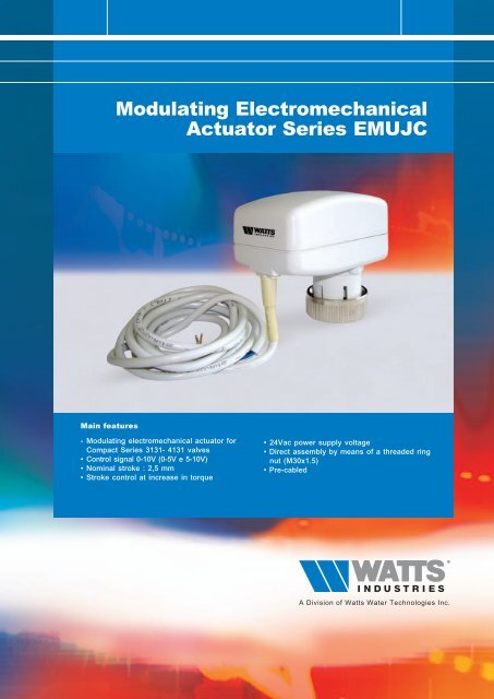
<strong>Modulating</strong> <strong>Electromechanical</strong><br />
<strong>Actuator</strong> <strong>Series</strong> EMUJC<br />
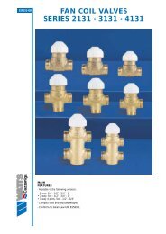
Main features<br />
- <strong>Modulating</strong> electromechanical actuator for<br />
Compact <strong>Series</strong> 3131- 4131 valves<br />
• Control signal 0-10V (0-5V e 5-10V)<br />
• Nominal stroke : 2,5 mm<br />
• Stroke control at increase in torque<br />
• 24Vac power supply voltage<br />
• Direct assembly by means of a threaded ring<br />
nut (M30x1.5)<br />
• Pre-cabled
MODULATING ELECTROMECHANICAL ACTUATOR<br />
Description<br />
2<br />
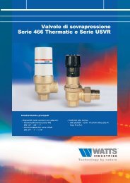
The <strong>Series</strong> EMUJC actuator is a modulating electromechanical actuator supplied with 24V by means of a<br />
three-point control or 0-10V (0-5V and 5-10V) control signal. Its distinguishing features are its compact size, which<br />
enables it to be installed in small spaces (fan coils, etc...) and its ease of assembly in that no hydraulic operations<br />
(system drainage) are required to couple the servo controls with the valve bodies. It also has a LED that signals<br />
its operating status.<br />
EMUJC<br />
<strong>Modulating</strong> electromechanical actuator powered with 24V by means of a 0-10V<br />
(0-5V and 5-10V) control signal. It has a LED indicating its operating status.<br />
Type Part no. Control Signal Power supply Cable length<br />
EMUJC EMUJC010 0 -10V (2 -10V) 24V 2000 mm<br />
Application<br />
The <strong>Series</strong> EMUJC electromechanical actuators coupled with Compact <strong>Series</strong> 3131 - 4131 valves, are used in<br />
heating and/or air-conditioning systems, to control the heat emission of the single terminal units.<br />
Operation<br />
The operation of the <strong>Series</strong> EMUJC actuator is based on the rotation of a shaft driven in either direction by a set<br />
of gears. The latter are, in turn, driven by a bidirectional synchronous motor through a magnetic coupling which<br />
limits the torque transmitted and therefore also the linear output force.<br />
The servomotor and valve (Fig. 1) are fixed to one another by means of a threaded ring nut which fits directly into<br />
the valve body itself, without any need for other tools.<br />
The movement of the actuator is transmitted to the stem of the valve by axial contact and is kept constant by<br />
means of a spring situated inside the valve body.<br />
In this way, the valve opening and closing forces are obtained, in one direction, through the thrust exerted<br />
by the servomotor (Fs opens way B, Fig. 2) and, in the other direction, through the force of the spring<br />
(Fm opens way A, Fig. 2) situated inside the valve itself.<br />
The <strong>Series</strong> EMUJC actuator allows the valve to be opened manually simply by removing the actuator from the<br />
valve body.<br />
<strong>Actuator</strong> – valve coupling by means of the threaded ring nut<br />
Fs<br />
Fm<br />
A<br />
AB<br />
B<br />
B<br />
Fig. 1<br />
Fig. 2
Action<br />
When the signal increases in Direct Action (DA) configurations or decreases in Reverse Action (RA)<br />
configurations, the motor moves a set of gears that push the valve stem straight downwards against the return<br />
spring.<br />
When the signal decreases in Direct Action configurations or increases in Reverse Action configurations, the<br />
actuator shaft retracts, thus allowing the valve return spring to restore the stem to its normal position.<br />
Jumper 5, Direct Action<br />
M<br />
0%<br />
1<br />
Jumper 2 Jumper 3<br />
50%<br />
2<br />
1<br />
2<br />
3<br />
3<br />
100%<br />
0 5 10 V<br />
Jumper 5, Reverse Action<br />
M<br />
0%<br />
4<br />
Jumper 2 Jumper 3<br />
4<br />
50%<br />
6<br />
5<br />
5<br />
6<br />
100%<br />
0 5 10 V<br />
Limit switch confirmation<br />
When the signal remains constant at the maximum or minimum level, to confirm the position, the motor is started<br />
every 2 hours for about 80 seconds.<br />
Self-calibration cycle<br />
When it is powered, the actuator automatically calibrates its limit switch position by performing a complete rotation.<br />
The actuator drives the stem downwards for about 80 seconds to the position of the input signal.<br />
Anti-blocking cycle<br />
When the anti-blocking cycle is enabled (ON), the actuator performs a complete rotation every 24 hours to remove<br />
any impurities that have accumulated in the plug and the valve seat. The anti-blocking function can be selected<br />
using jumper 1.<br />
Operating LED indications<br />
ON<br />
Single blink<br />
Double blink<br />
OFF<br />
Power supply present, motor off.<br />
• Floating actuator : time out<br />
• Proportional actuator : running<br />
Motor on<br />
The actuator executes a limit switch confirmation or anti-blocking cycle<br />
Power supply not present
MODULATING ELECTROMECHANICAL ACTUATOR<br />
Calibration (Jumper setting)<br />
Position of jumper on the card :<br />
Jumper in position :<br />
4<br />
Jumper not in position :<br />
1<br />
2<br />
3<br />
4<br />
5<br />
6<br />
Function Jumper No. Factory setting<br />
Alternative setting<br />
Anti-blocking<br />
1<br />
Enabled<br />
Disabled<br />
Input signal<br />
control<br />
2<br />
3<br />
0....10 V<br />
5....10 V<br />
0....5 V<br />
No function<br />
4<br />
No function<br />
......<br />
Action<br />
No function<br />
5<br />
6<br />
Direct (DA)<br />
No function<br />
Reverse (RA)<br />
..........<br />
Factory Calibration<br />
The setting of the modulating version is 0/10V in direct action. With 0V, the valve will be fully open.<br />
Technical characteristics<br />
Models<br />
EMUJC010<br />
Action/Control Proportional (0...10 V, 0...5 V or 5...10 V)<br />
Power supply (50/60 Hz) 24 VAC ±15%<br />
Input impedance<br />
80 kΩ<br />
Power consumption<br />
Apparent : 2.7 VA when on<br />
Active : 2 W<br />
Nominal force 120 N +30% / -20%<br />
Maximum conventional stroke 2,5 mm when used together with valves 3131 and 4131<br />
Maximum conventional stroke<br />
15 s/mm<br />
Protezione IP40 (EN 60529)<br />
Material :<br />
Cover / Shaft<br />
PA66 - Glass + (30% total) Kelon A FR CETG/300-V0<br />
Ring nut<br />
Brass CuZn40Pb2<br />
Coupling M30 x 1.5<br />
Colour of cover<br />
RAL7035<br />
Ambient operating conditions<br />
from 0 °C a 50 °C, without condensation<br />
Storage conditions<br />
from -20 °C a 65 °C, without condensation<br />
Maximum fluid temperature 95 °C<br />
Electrical connections<br />
flexible cable 2 m, Ø 4.5 mm<br />
Operating status<br />
LED<br />
Noise<br />
MODULATING ELECTROMECHANICAL ACTUATOR<br />
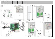
Installation<br />
5<br />
Never use the actuator as a lever for assembling parts.<br />
Max 90° Max 90°<br />
OK<br />
OK<br />
Electrical Connections<br />
The wiring diagram is illustrated on the outside of the motor casing.<br />
The ends of the connecting cable are to be connected as shown in Table 1.<br />
Table 1<br />
0-10V VERSION<br />
Operation<br />
Power supply : neutral<br />
Power supply : phase<br />
Positive control signal (+)<br />
Negative control signal (-)<br />
(*) Cable colour<br />
Blue<br />
Red<br />
White<br />
(**) Black<br />
M<br />
PRINTED CIRCUIT BOARD<br />
(*) These colours may vary:<br />
see the electric wiring label or the instructions sheet<br />
attached to the motor.<br />
(**) For control units that also have a negative output signal (-),<br />
it must be connected to the neutral wire of the power<br />
supply.<br />
Red<br />
Black<br />
Blue<br />
White<br />
com 0.....10V input<br />
control signal<br />
common<br />
24 V <br />
Connecting Instructions<br />
WARNING :<br />
During assembly and maintenance, make sure that :<br />
• The power supply is shut off to eliminate the risk of damage to the equipment and injury to persons.<br />
• Do not touch, connect or disconnect wires with the power supply turned on.<br />
When making the electrical connections, follow the instructions given below :<br />
• Before making the connection, make sure that the power supply is off or disconnected to eliminate the risk<br />
of damage to the material and injury to persons.<br />
• Make sure that the power supply conforms to the specifications given on the cover of the actuator.<br />
All connections must comply with the laws and regulations in force and must be made by specialized staff.
MODULATING ELECTROMECHANICAL ACTUATOR<br />
Overall dimensions (mm)<br />
6<br />
EMUJC<br />
74<br />
I<br />
I<br />
h<br />
h<br />
69.5<br />
M 30 X 1.5<br />
47<br />
55<br />
3131 - EMUJC 4131 - EMUJC<br />
a<br />
b<br />
a<br />
b<br />
L<br />
Valve / actuator coupling<br />
2131<br />
3131<br />
4131<br />
0…10V (2-10V) Version<br />
Diameter a b h i l<br />
1/2” 55 26 105 - 32<br />
3/4” 55 28 105 - 32<br />
1” 55 41 132 - 47<br />
1/2” 55 26 118 - 32<br />
3/4” 55 28 120 - 32<br />
1” 55 41 155 - 49<br />
1/2” 55 26 145 35 31<br />
3/4” 55 28 158 50 33<br />
Re-order no. 69-0016-UK-IT/1-07-08-Rev.0<br />
The descriptions and photos contained in this brochure are supplied by way of information only and are not binding.<br />
<strong>Watts</strong> <strong>Industries</strong> reserves the right to make any technical or design improvements to its products without prior notice.<br />
<strong>Watts</strong> <strong>Industries</strong> Italia S.r.l.<br />
Via Brenno, 21 - 20046 Biassono (MI), Italy<br />
Ph. : +39 039 4986.1 - Fax : +39 039 4986.222<br />
e-mail : info@wattsindustries.it<br />
www.wattsindustries.com