Owner's Manual & Safety Instructions - Harbor Freight Tools
Owner's Manual & Safety Instructions - Harbor Freight Tools
Owner's Manual & Safety Instructions - Harbor Freight Tools

You also want an ePaper? Increase the reach of your titles
YUMPU automatically turns print PDFs into web optimized ePapers that Google loves.
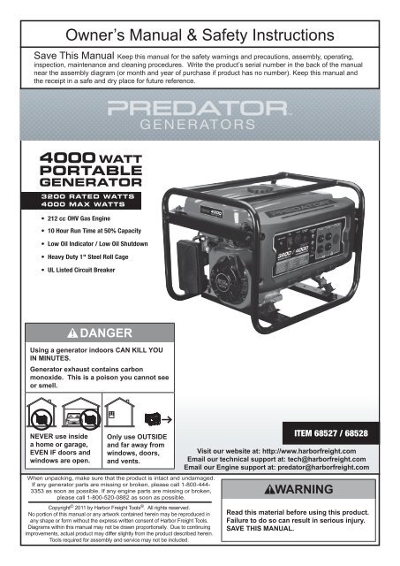
Owner’s <strong>Manual</strong> & <strong>Safety</strong> <strong>Instructions</strong><br />
Save This <strong>Manual</strong> Keep this manual for the safety warnings and precautions, assembly, operating,<br />
inspection, maintenance and cleaning procedures. Write the product’s serial number in the back of the manual<br />
near the assembly diagram (or month and year of purchase if product has no number). Keep this manual and<br />
the receipt in a safe and dry place for future reference.<br />
Using a generator indoors CAN KILL YOU<br />
IN MINUTES.<br />
Generator exhaust contains carbon<br />
monoxide. This is a poison you cannot see<br />
or smell.<br />
NEVER use inside<br />
a home or garage,<br />
EVEN IF doors and<br />
windows are open.<br />
Only use OUTSIDE<br />
and far away from<br />
windows, doors,<br />
and vents.<br />
When unpacking, make sure that the product is intact and undamaged.<br />
If any generator parts are missing or broken, please call 1-800-444-<br />
3353 as soon as possible. If any engine parts are missing or broken,<br />
please call 1-800-520-0882 as soon as possible.<br />
Copyright © 2011 by <strong>Harbor</strong> <strong>Freight</strong> <strong>Tools</strong> ® . All rights reserved.<br />
No portion of this manual or any artwork contained herein may be reproduced in<br />
any shape or form without the express written consent of <strong>Harbor</strong> <strong>Freight</strong> <strong>Tools</strong>.<br />
Diagrams within this manual may not be drawn proportionally. Due to continuing<br />
improvements, actual product may differ slightly from the product described herein.<br />
<strong>Tools</strong> required for assembly and service may not be included.<br />
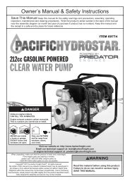
ITEM 68527 / 68528<br />
Visit our website at: http://www.harborfreight.com<br />
Email our technical support at: tech@harborfreight.com<br />
Email our Engine support at: predator@harborfreight.com<br />
Read this material before using this product.<br />
Failure to do so can result in serious injury.<br />
Save this manual.
Table of Contents<br />
<strong>Safety</strong> Setup<br />
Operation Maintenance<br />
<strong>Safety</strong>.......................................................... 2<br />
Setup........................................................... 6<br />
Specifications.............................................. 6<br />
Operation..................................................... 8<br />
WARNING SYMBOLS AND DEFINITIONS<br />
Maintenance............................................... 14<br />
Parts List and Diagram............................... 20<br />
Warranty..................................................... 23<br />
This is the safety alert symbol. It is used to alert you to potential personal injury hazards.<br />
Obey all safety messages that follow this symbol to avoid possible injury or death.<br />
Indicates a hazardous situation which, if not avoided,<br />
will result in death or serious injury.<br />
Indicates a hazardous situation which, if not avoided,<br />
could result in death or serious injury.<br />
Indicates a hazardous situation which, if not avoided,<br />
could result in minor or moderate injury.<br />
Addresses practices not related to personal injury.<br />
IMPORTANT SAFETY INSTRUCTIONS<br />
<strong>Instructions</strong> Pertaining to a Risk of Fire,<br />
Electric Shock, or Injury to Persons<br />
WARNING – When using tools, basic precautions should always be followed, including the following:<br />
Set up Precautions<br />
1. Gasoline fuel and fumes are flammable,<br />
and potentially explosive. Use proper fuel<br />
storage and handling procedures. Do not store<br />
fuel or other flammable materials nearby.<br />
2. Have multiple ABC class fire<br />
extinguishers nearby.<br />
3. Operation of this equipment may create sparks<br />
that can start fires around dry vegetation. A<br />
spark arrestor may be required. The operator<br />
should contact local fire agencies for laws or<br />
regulations relating to fire prevention requirements.<br />
4. Set up and use only on a flat, level,<br />
well‐ventilated surface.<br />
5. All connections and conduits from the<br />
Generator to the load must only be installed<br />
by trained and licensed electricians, and<br />
in compliance with all relevant local, state,<br />
and federal electrical codes and standards,<br />
and other regulations where applicable.<br />
6. Connections for standby power to a building<br />
electrical system must be made by a qualified<br />
electrician. The connection must isolate the<br />
generator power from utility power, and must comply<br />
with all applicable laws and electrical codes.<br />
7. Wear ANSI-approved safety goggles,<br />
heavy-duty work gloves, and dust<br />
mask/respirator during set up.<br />
Page 2<br />
For Pump technical questions, please call 1-800-444-3353.<br />
For Engine technical questions, please call 1-800-520-0882.<br />
Item 68527 / 68528
Set up Precautions (cont.)<br />
8. Use only lubricants and fuel<br />
recommended in this manual.<br />
9. Improper connections to a building electrical<br />
system can allow electrical current from the<br />
generator to backfeed into the utility lines. Such<br />
backfeed may electrocute utility company workers<br />
or others who contact the lines during a power<br />
outage, and the generator may explode, burn, or<br />
cause fires when utility power is restored. Consult<br />
the utility company and a qualified electrician if<br />
intending to use the generator for back up power.<br />
10. Do not operate the Generator before grounding.<br />
The Generator must be earth-grounded<br />
in accordance with all relevant electrical<br />
codes and standards before operation.<br />
<strong>Safety</strong><br />
Operating Precautions<br />
1. Carbon Monoxide Hazard<br />
Using a generator indoors CAN KILL<br />
YOU IN MINUTES.<br />
Generator exhaust contains carbon<br />
monoxide. This is a poison you cannot<br />
see or smell.<br />
NEVER use inside a home or garage, EVEN IF doors<br />
and windows are open.<br />
Only use OUTSIDE and far away from windows,<br />
doors, and vents.<br />
2. Never use a generator indoors, including in<br />
garages, basements, crawl spaces and sheds.<br />
Opening doors and windows or using fans will NOT<br />
prevent carbon monoxide build up in the home.<br />
3. When using generators, keep them outdoors<br />
and far away from open doors, windows,<br />
and vents to avoid toxic levels of carbon<br />
monoxide from building up indoors.<br />
4. If you start to feel sick, dizzy, or weak while<br />
using a generator, get to fresh air right away.<br />
The carbon monoxide from generators can<br />
quickly lead to full incapacitation and death.<br />
5. Keep children away from the equipment,<br />
especially while it is operating.<br />
6. Keep all spectators at least six feet<br />
from the Engine during operation.<br />
7. Fire Hazard! Do not fill gas tank while engine<br />
is running. Do not operate if gasoline has been<br />
spilled. Clean spilled gasoline before starting engine.<br />
Do not operate near pilot light or open flame.<br />
8. Do not touch engine during use. Let engine<br />
cool down before service or storage.<br />
9. Never store fuel or other flammable<br />
materials near the engine.<br />
10. If the plugged in product operates abnormally<br />
or unusually slow, immediately stop using the<br />
generator as a power source. Always read and<br />
adhere to the instruction manual of the product<br />
to be powered, to make sure that it can be safely<br />
and efficiently powered by a portable generator.<br />
11. Before connecting an appliance or power<br />
cord to the generator: Make sure that it is in<br />
good working order. Faulty appliances or power<br />
cords can create a potential for electrical shock.<br />
12. Do not exceed the maximum power rating of<br />
the generator. Make sure that the total electrical<br />
rating of the all of the tools or appliances plugged<br />
into the generator at the same time does not<br />
exceed that of the generator. Check that the startup<br />
surge will not be beyond the limit of the Generator.<br />
Power levels between rated and maximum<br />
may be used for no more than 30 minutes.<br />
13. Avoid substantially overloading which will<br />
trip the circuit breaker. Exceeding the time<br />
limit for maximum power operation or slightly<br />
overloading the generator may not switch the<br />
circuit breaker or circuit protector OFF, but will<br />
shorten the service life of the generator.<br />
14. Do not attempt to connect or disconnect<br />
load connections while standing in<br />
water, or on wet or soggy ground.<br />
15. Do not touch electrically energized parts of<br />
the Generator and interconnecting cables<br />
or conductors with any part of the body, or<br />
with any non-insulated conductive object.<br />
Maintenance Operation<br />
Setup<br />
For Pump technical questions, please call 1-800-444-3353.<br />
Item 68527 / 68528 For Engine technical questions, please call 1-800-520-0882.<br />
Page 3
Operating Precautions (cont.)<br />
<strong>Safety</strong> Setup<br />
Operation Maintenance<br />
16. Connect the Generator only to a load or<br />
electrical system (120 volt or 240 volt) that is<br />
compatible with the electrical characteristics<br />
and rated capacities of the Generator.<br />
17. Insulate all connections and disconnected wires.<br />
18. Guard against electric shock. Prevent<br />
body contact with grounded surfaces such as<br />
pipes, radiators, ranges, and refrigerators.<br />
19. Only use a suitable means of transport and<br />
lifting devices with sufficient weight bearing<br />
capacity when transporting the generator.<br />
20. Secure the Generator on transport vehicles to<br />
prevent the tool from rolling, slipping, and tilting.<br />
21. Industrial applications must<br />
follow OSHA requirements.<br />
22. Do not leave the Generator unattended when it is<br />
running. Turn off the Generator (and remove safety<br />
keys, if available) before leaving the work area.<br />
23. The Generator engine can produce high<br />
noise levels. Prolonged exposure to noise levels<br />
above 85 dBA is hazardous to hearing. Always<br />
wear ear protection when operating or working<br />
around the gas engine while it is operating.<br />
24. Wear ANSI-approved safety glasses and<br />
hearing protection during use.<br />
25. People with pacemakers should consult their<br />
physician(s) before use. Electromagnetic<br />
fields in close proximity to a heart pacemaker<br />
could cause pacemaker interference or<br />
pacemaker failure. Caution is necessary when<br />
near the engine’s magneto or recoil starter.<br />
26. Use only accessories that are recommended<br />
by <strong>Harbor</strong> <strong>Freight</strong> <strong>Tools</strong> for your model.<br />
Accessories that may be suitable for one<br />
piece of equipment may become hazardous<br />
when used on another piece of equipment.<br />
27. Do not operate in explosive atmospheres,<br />
such as in the presence of flammable<br />
liquids, gases, or dust. Gasoline-powered<br />
engines may ignite the dust or fumes.<br />
28. Keep grounded conductive objects, such as<br />
tools, away from exposed, live electrical parts<br />
and connections to avoid sparking or arcing.<br />
These events could ignite fumes or vapors.<br />
29. Stay alert, watch what you are doing<br />
and use common sense when operating<br />
this piece of equipment. Do not use this<br />
piece of equipment while tired or under the<br />
influence of drugs, alcohol or medication.<br />
30. Dress properly. Do not wear loose clothing or<br />
jewelry. Keep hair, clothing and gloves away<br />
from moving parts. Loose clothes, jewelry or<br />
long hair can be caught in moving parts.<br />
31. Parts, especially exhaust system components,<br />
get very hot during use. Stay clear of hot parts.<br />
32. Do not cover the generator or its<br />
engine during operation.<br />
33. Keep the generator, its engine, and<br />
surrounding area clean at all times.<br />
34. Use the generator, accessories, etc., in<br />
accordance with these instructions and in<br />
the manner intended for the particular type of<br />
equipment, taking into account the working<br />
conditions and the work to be performed. Use<br />
of the equipment for operations different from those<br />
intended could result in a hazardous situation.<br />
35. Do not operate the generator with known<br />
leaks in the engine’s fuel system.<br />
36. This product contains or, when used,<br />
produces a chemical known to the State of<br />
California to cause cancer and birth defects<br />
or other reproductive harm. (California<br />
Health & <strong>Safety</strong> Code § 25249.5, et seq.)<br />
37. When spills of fuel or oil occur, they must<br />
be cleaned up immediately. Dispose of fluids<br />
and cleaning materials as per any local, state, or<br />
federal codes and regulations. Store oil rags in<br />
a bottom-ventilated, covered, metal container.<br />
38. Keep hands and feet away from moving parts. Do<br />
not reach over or across generator while operating.<br />
39. Before use, check for misalignment or binding<br />
of moving parts, breakage of parts, and any<br />
other condition that may affect the generator’s<br />
operation. If damaged, have the generator<br />
serviced before using. Many accidents are<br />
caused by poorly maintained equipment.<br />
40. Use the correct generator for the<br />
application. Do not modify the generator or<br />
its engine, and do not use the generator for<br />
a purpose for which it is not intended.<br />
Page 4<br />
For Pump technical questions, please call 1-800-444-3353.<br />
For Engine technical questions, please call 1-800-520-0882.<br />
Item 68527 / 68528
Service Precautions<br />
1. Before service, maintenance, or cleaning:<br />
a. Unplug all devices from the generator.<br />
b. Turn the engine switch to its “OFF” position.<br />
c. Allow the engine to completely cool.<br />
d. Then, remove the spark plug<br />
cap from the spark plug.<br />
2. Keep all safety guards in place and in<br />
proper working order. <strong>Safety</strong> guards include<br />
muffler, air cleaner, mechanical guards,<br />
and heat shields, among other guards.<br />
3. Keep all electrical equipment clean and<br />
dry. Replace any wiring where the insulation is<br />
cracked, cut, abraded, or otherwise degraded.<br />
Replace terminals that are worn, discolored, or<br />
corroded. Keep terminals clean and tight.<br />
4. Do not alter or adjust any part of the<br />
equipment or its engine that is sealed by the<br />
manufacturer or distributor. Only a qualified<br />
service technician may adjust parts that may<br />
increase or decrease governed engine speed.<br />
5. Wear ANSI-approved safety goggles,<br />
heavy-duty work gloves, and dust<br />
mask/respirator during service.<br />
6. Maintain labels and nameplates on<br />
the equipment. These carry important<br />
information. If unreadable or missing, contact<br />
<strong>Harbor</strong> <strong>Freight</strong> <strong>Tools</strong> for a replacement.<br />
7. Have the equipment serviced by a qualified<br />
repair person using only identical replacement<br />
parts. This will ensure that the safety of the<br />
equipment is maintained. Do not attempt any service<br />
or maintenance procedures not explained in this<br />
manual or any procedures that you are uncertain<br />
about your ability to perform safely or correctly.<br />
8. Store equipment out of the reach of children.<br />
9. Follow scheduled engine and<br />
equipment maintenance.<br />
Refueling:<br />
1. Do not smoke, or allow sparks, flames,<br />
or other sources of ignition around the<br />
equipment, especially when refuelling.<br />
2. Do not refill the fuel tank while the<br />
engine is running or hot.<br />
3. To prevent fuel leakage and fire<br />
hazard, Do not overfill with fuel. Fill with<br />
fuel according to the Fuel Level information<br />
below the Specification chart for your model.<br />
4. Do not fill fuel tank to the top. Leave a little<br />
room for the fuel to expand as needed.<br />
5. Refuel in a well-ventilated area only.<br />
6. Wipe up any spilled fuel and allow excess<br />
to evaporate before starting engine. To<br />
prevent fire, do not start the engine<br />
while the smell of fuel hangs in the air.<br />
Save these<br />
instructions.<br />
<strong>Safety</strong><br />
Maintenance Operation<br />
Setup<br />
For Pump technical questions, please call 1-800-444-3353.<br />
Item 68527 / 68528 For Engine technical questions, please call 1-800-520-0882.<br />
Page 5
Functional Description<br />
Specifications<br />
<strong>Safety</strong> Setup<br />
Operation Maintenance<br />
Rated Output<br />
120/240V~, 60Hz<br />
3,200 Watts (4,000 max)<br />
Generator<br />
Phase<br />
Single<br />
Two 3-Prong, duplex NEMA #5-15 120V<br />
Electrical Receptacle<br />
One 4-Prong, NEMA #L14-30 twistlock 120V/240V<br />
One DC Outlet 12VDC<br />
Displacement<br />
212cc<br />
Engine Type<br />
Horizontal Single Cylinder 4 stroke OHV<br />
Cooling System<br />
Forced air cooled<br />
Engine<br />
Type 87+ octane unleaded gasoline<br />
Fuel<br />
Capacity 4 Gallons (15L)<br />
10W-30 above 32° F<br />
Type SAE<br />
Engine Oil<br />
5W-30 at 32° F or below<br />
Capacity .6 Quart (.6L)<br />
Run Time @ 50% load<br />
10 hr.<br />
Operational Volume<br />
70 dB<br />
Available accessories<br />
Wheel kit (sold separately)<br />
Item 68527 - The emission control system for this Generator’s Engine is warranted for standards set by the U.S.<br />
Environmental Protection Agency and by the California Air Resources Board (also known as CARB). For warranty<br />
information, refer to the last pages of this manual.<br />
Item 68528 - The emission control system for this Generator’s Engine is warranted for standards set by the U.S.<br />
Environmental Protection Agency. For warranty information, refer to the last pages of this manual.<br />
Components and Controls<br />
Fuel Valve<br />
Frame<br />
Choke<br />
Air Filter<br />
Fuel Cap<br />
Starter<br />
Handle<br />
DC Receptacle<br />
DC Circuit Breaker<br />
Low Oil Indicator<br />
Power Switch<br />
AC Circuit Breakers<br />
Ground Terminal<br />
AC Receptacles<br />
Page 6<br />
For Pump technical questions, please call 1-800-444-3353.<br />
For Engine technical questions, please call 1-800-520-0882.<br />
Item 68527 / 68528
Components and Controls (cont.)<br />
The following are descriptions of the controls<br />
on the power panel. Your generator has<br />
sockets to power your products with circuit<br />
breakers to protect the voltage flow.<br />
i<br />
O<br />
3.<br />
ON<br />
OFF<br />
Circuit Breakers: The circuit breaker protects the<br />
Generator from overloading. The rating of the breaker<br />
and the load it protects are marked near the breaker.<br />
Should any of the Circuit Breakers trip, the Generator<br />
will stop the electricity output. If this happens, unplug<br />
all loads from the Generator. Allow the Generator to<br />
cool down. Then, press the tripped Circuit Breaker,<br />
restart the Engine, and re-attach loads.<br />
<strong>Safety</strong><br />
1.<br />
Engine Switch: Used to start and stop the Engine.<br />
2. AC Receptacles: The Generator contains several<br />
AC Receptacles to power tools and equipment.<br />
4. DC Outlet Receptacle: 12 VDC outlet receptacle set<br />
provides a power source for 12 volt DC items.<br />
a. 3-Prong, duplex<br />
120 volt AC Receptacle<br />
(NEMA #5-15)<br />
b. 4-Prong, twistlock<br />
120/240 volt AC Receptacle<br />
(NEMA #L14-30)<br />
WARNING! Connect tools and equipment<br />
only to the AC Receptacle that is compatible with<br />
the electrical characteristics and rated capacities<br />
of the tools and equipment being used.<br />
5. Grounding Terminal: Prior to each use, set<br />
up the ground wire (not included) connection<br />
to the Grounding Terminal to properly ground<br />
the Generator. See Set up instructions<br />
to properly ground the Generator.<br />
Maintenance Operation<br />
Setup<br />
For Pump technical questions, please call 1-800-444-3353.<br />
Item 68527 / 68528 For Engine technical questions, please call 1-800-520-0882.<br />
Page 7
Initial Tool Set Up/Assembly<br />
<strong>Safety</strong> Setup<br />
Operation Maintenance<br />
Read the entire Important<br />
<strong>Safety</strong> Information section at the<br />
beginning of this manual including<br />
all text under subheadings therein<br />
before set up or use of this product.<br />
To prevent serious injury:<br />
Operate only with proper spark arrestor installed.<br />
Operation of this equipment may create sparks that<br />
can start fires around dry vegetation.<br />
A spark arrestor may be required.<br />
The operator should contact local fire<br />
agencies for laws or regulations relating<br />
to fire prevention requirements.<br />
Note: For additional information regarding the parts listed in the following pages,<br />
refer to the Assembly Diagram near the end of this manual.<br />
Note: Wheel Kit, item # 68531 (sold separately) can be used with this generator.<br />
Grounding<br />
The Generator must be properly grounded before<br />
use. Have the unit grounded by a qualified<br />
electrician if you are not qualified to do so.<br />
Operating <strong>Instructions</strong><br />
At high altitudes, the engine’s carburetor, governor,<br />
and any other parts that control the fuel-air ratio will<br />
need to be adjusted by a qualified mechanic to allow<br />
efficient high-altitude use and to prevent damage to the<br />
engine and any other devices used with this product.<br />
CAUTION: This generator is not intended to power<br />
sensitive electronic equipment without the addition of an<br />
appropriate line conditioner and surge protector (both not<br />
included). Sensitive electronic equipment includes,<br />
but is not limited to, audio/video equipment, some<br />
television sets, computers, and printers. Sensitive<br />
electronic equipment should be operated on approved<br />
inverter type generators or pure sine wave generators.<br />
To ground the Generator, connect a #6 AWG<br />
grounding wire (not included) from the Grounding<br />
Terminal on the Control Panel to a grounding rod<br />
(not included) that has been driven at least 24<br />
inches deep into the earth. The grounding rod must<br />
be an earth-driven copper or brass rod (electrode)<br />
which can adequately ground the Generator.<br />
Read the entire Important <strong>Safety</strong> Information section at the beginning of this<br />
manual including all text under subheadings therein before set up or use of this product.<br />
Inspect tool before use, looking for damaged, loose, and missing parts.<br />
If any problems are found, do not use tool until repaired.<br />
Generator Pre-Start Checks<br />
Inspect engine and equipment, looking for<br />
damaged, loose, and missing parts before set<br />
up and starting. If any problems are found,<br />
do not use equipment until fixed properly.<br />
Checking and Filling Engine Oil<br />
CAUTION! Your Warranty is VOID if the engine’s<br />
crankcase is not properly filled with oil before each<br />
use.<br />
Before each use, check the oil level. Do not run the<br />
engine with low or no engine oil.<br />
Running the engine with no or low engine oil<br />
WILL permanently damage the engine.<br />
1. Make sure the engine is stopped and is level.<br />
2. Close the Fuel Valve.<br />
3. Clean the top of the Dipstick and the area around it.<br />
Remove the Dipstick by threading it counterclockwise,<br />
and wipe it off with a clean lint free rag.<br />
4.<br />
Full level<br />
Full level<br />
Reinsert the Dipstick without threading it in and<br />
remove it to check the oil level. The oil level<br />
should be up to the full level as shown above.<br />
Page 8<br />
For Pump technical questions, please call 1-800-444-3353.<br />
For Engine technical questions, please call 1-800-520-0882.<br />
Item 68527 / 68528
Generator Pre-Start Checks (cont.)<br />
5. If the oil level is at or below the low mark add the<br />
appropriate type of oil until the oil level is at the<br />
proper level. SAE 10W‐30 oil is recommended<br />
for general use. (The SAE Viscosity Grade chart<br />
on page 15 in the Service section shows other<br />
viscosities to use in different average temperatures.)<br />
6. Thread the dipstick back in clockwise.<br />
CAUTION! Do not run the engine with too little<br />
oil. The engine will be permanently damaged.<br />
Checking and Filling Fuel<br />
WARNING! To prevent serious<br />
injury from fire:<br />
Fill the fuel tank in a well-ventilated area<br />
away from ignition sources. If the engine is<br />
hot from use, shut the engine off and wait<br />
for it to cool before adding fuel.<br />
Do not smoke.<br />
Using the Generator<br />
Before Starting the Generator Engine<br />
Before starting the engine:<br />
a. Follow the Set Up <strong>Instructions</strong><br />
to prepare the Generator.<br />
b. Unplug all loads from the Generator.<br />
c. Inspect the Generator and engine.<br />
d. Fill the engine with the proper amount<br />
and type of both fuel and oil.<br />
1. Clean the Fuel Cap and the area around it.<br />
2. Unscrew and remove the Fuel Cap.<br />
3. If needed, fill the Fuel Tank to about 1 inch<br />
under the fill neck of the Fuel Tank with 87<br />
octane or higher unleaded gasoline.<br />
Note: Do not use gasoline containing more than<br />
10% ethanol (E10). Do not use E85 ethanol.<br />
Note: Do not use gasoline that has been stored in a<br />
metal fuel container or a dirty fuel container. It can<br />
cause particles to enter the carburetor, effecting<br />
engine performance and/or causing damage.<br />
4. Then, replace the Fuel Cap.<br />
IMPORTANT: After starting the engine, allow it to run at no load for five minutes<br />
with no load after each start‐up so that the engine can stabilize.<br />
5. Wipe up any spilled fuel and allow excess<br />
to evaporate before starting engine.<br />
To prevent FIRE, do not start the engine<br />
while the smell of fuel hangs in the air.<br />
Basic Generator Use Procedure<br />
See following pages for specific instructions<br />
1. Check that the generator can handle the<br />
wattage needed to power your products.<br />
2. Start the Engine, and allow the Engine and<br />
Generator to run and warm up for five minutes<br />
after starting with no electrical load.<br />
3. Plug in products.<br />
4. When finished using the Generator,<br />
disconnect all electrical loads.<br />
Note: Do not allow generator to run<br />
out of fuel with loads attached.<br />
5. Turn off the Engine.<br />
6. Allow the Generator and its Engine to<br />
completely cool. Then store the unit in a<br />
clean, dry, safe location out of reach of<br />
children and other unauthorized people.<br />
7. Break-in Period:<br />
a. Breaking-in the engine will help to ensure proper equipment and engine operation.<br />
b. The operational break-in period will last about 3 hours of use. During this period:<br />
• Do not apply a heavy load to the equipment.<br />
c. The maintenance break-in period will last about 20 hours of use. After this period:<br />
• Change the engine oil.<br />
Under normal operating conditions subsequent maintenance follows<br />
the schedule explained in the Service section.<br />
<strong>Safety</strong><br />
Maintenance Operation<br />
Setup<br />
For Pump technical questions, please call 1-800-444-3353.<br />
Item 68527 / 68528 For Engine technical questions, please call 1-800-520-0882.<br />
Page 9
Starting the Engine<br />
1. To start a cold engine, move the Choke to the<br />
CHOKE position.<br />
To restart a warm engine, leave the Choke in the<br />
RUN position.<br />
<strong>Safety</strong> Setup<br />
Operation Maintenance<br />
2. Open the Fuel Valve.<br />
3. Turn the Engine Switch to ON.<br />
4. Grip the Starter Handle of the Engine loosely and pull it<br />
slowly several times to allow the gasoline to flow into the<br />
Engine’s carburetor. Then pull the Starter Handle gently<br />
until resistance is felt. Allow Cable to retract fully and<br />
then pull it quickly. Repeat until the engine starts.<br />
Note: Do not let the Starter Handle snap back against<br />
the engine. Hold it as it recoils so it doesn’t hit<br />
the engine.<br />
5. Allow the Engine to run for several seconds.<br />
Then, if the Choke lever is in the CHOKE position,<br />
move the Choke Lever very slowly to its RUN position.<br />
NOTE: Moving the Choke Lever too fast could stall the engine.<br />
i<br />
O<br />
ON<br />
IMPORTANT: Allow the engine to run at no load for five minutes with no<br />
load after each start‐up so that the engine can stabilize.<br />
Page 10<br />
For Pump technical questions, please call 1-800-444-3353.<br />
For Engine technical questions, please call 1-800-520-0882.<br />
Item 68527 / 68528
Connecting Electrical Loads<br />
Familiarize yourself with the engine controls, power panel and how to start the engine before using the generator.<br />
Calculate the wattage of the products you will use with the generator and verify that the generator can handle the<br />
total load.<br />
WARNING! Connect only properly wired plugs to the generator.<br />
A plug that is spliced onto a different cord may be hazardous.<br />
Only a qualified electrician should wire a plug onto a cord.<br />
CAUTION Never exceed the rated capacity for this Generator,<br />
as serious damage to the Generator and/or appliances, tools, and<br />
equipment could result from an overload. Starting and running<br />
wattage requirements should always be calculated when matching this<br />
Generator’s wattage capacity to the appliance, tool, or equipment.<br />
Use the DC12V Receptacle to power 12VDC equipment.<br />
WARNING! Do not charge batteries without a proper charge controller. Do not overcharge.<br />
a. Connect the items that require the most wattage first.<br />
b. Connect “inductive” load appliances, tools, and equipment next.<br />
Inductive loads are small hand tools and some small appliances.<br />
c. Connect any lights next.<br />
d. Voltage sensitive appliances, tools, and equipment should be the last to be connected to the Generator.<br />
Plug voltage sensitive items such as TV’s, DVD players, microwaves, and cordless telephones into a UL®<br />
Listed voltage surge protector (not included). Then, connect the surge protector into the Generator.<br />
IMPORTANT! Failure to connect and operate appliances, tools, and equipment in this sequence can cause<br />
damage to the Generator, appliances, tools, and equipment and will void the Warranty of this Generator.<br />
NOTE: If Engine speed or voltage fluctuates with a load below the Generator’s rated watts, move the Engine Choke<br />
Lever to the “HALF-CHOKE” position.<br />
IF ANY CIRCUIT BREAKERS TRIP CHECK THE FOLLOWING:<br />
1. Make sure that ALL circuit breakers are reset<br />
before starting the generator again.<br />
2. Adjust the plugs so the loads are<br />
shared across outlet circuits.<br />
To achieve rated output from the generator,<br />
distribute loads over outlets.<br />
t<br />
0) 1,000<br />
400<br />
) 200<br />
600) 600<br />
total Running Watts<br />
(must be less than 3,200)<br />
2,200<br />
est additional Start-up Watts 600<br />
tup Watts needed for all loads<br />
(must be less than 4,000)<br />
2,800<br />
Evenly distributed<br />
over outlets:<br />
<strong>Safety</strong><br />
Maintenance Operation<br />
Setup<br />
For Pump technical questions, please call 1-800-444-3353.<br />
Item 68527 / 68528 For Engine technical questions, please call 1-800-520-0882.<br />
Page 11
Calculating Total Wattage of Devices Used with the Generator<br />
<strong>Safety</strong> Setup<br />
Operation Maintenance<br />
Before using the Generator, check that the products<br />
you want to plug into the unit are below the rated and<br />
maximum wattage ratings of the Generator. Use the<br />
Wattage Calculation Table below, and the watts listed<br />
on your products, to help calculate multiple<br />
wattage totals.<br />
To use the table:<br />
1. Add up the Running Watts for all items you<br />
would like to use at any given time<br />
2. Make sure that this total is under the<br />
3200 rated wattage of the generator.<br />
3. Find the single highest starting watts for<br />
the selected items and add to the total.<br />
4. Make sure that this total is under the 4000<br />
maximum rated wattage of the generator.<br />
5. Plug in and turn on products from largest wattage<br />
to smallest.<br />
Wattage Calculation Table<br />
Equipment<br />
Total Running Watts<br />
(must be less than 3,200)<br />
Largest Additional Start-up Watts<br />
Total Startup Watts needed for all loads<br />
(must be less than 4,000)<br />
Example<br />
Equipment<br />
Running<br />
Watts<br />
Microwave (1,000 +200) 1,000<br />
Television (400 + 0) 400<br />
Box Fan (200 + 200) 200<br />
Hand Drill (600 + 600) 600<br />
Total Running Watts<br />
(must be less than 3,200)<br />
2,200<br />
Largest Additional Start-up Watts 600<br />
Total Startup Watts needed for all loads<br />
(must be less than 4,000)<br />
2,800<br />
Running<br />
Watts<br />
A generator that is rated more than the minimum<br />
required peak watts will last much longer than a<br />
generator that only supplies the exact watts needed.<br />
To Calculate Wattage<br />
Volts and amps can be multiplied together to get watts (volts x<br />
amps = watts).<br />
To Calculate Additional Start-Up Watts<br />
(If They Are Not Listed)<br />
For equipment with a motor: Use the rated watts<br />
amount as an estimate of additional Start-up Watts.<br />
For most lights or heaters:<br />
there are no additional start-up watts.<br />
Device<br />
Device<br />
JOB SITE<br />
Running<br />
Watts<br />
Additional<br />
Start-up<br />
Watts<br />
Air Compressor - 1/2 HP 1000 1000<br />
Table Saw - 10" 1700 1300<br />
Belt Sander - 3" 1200 1200<br />
Hand Drill - 1/2" 600 600<br />
Halogen Work Light 1000 0<br />
Recipricating Saw 900 900<br />
Device<br />
Device<br />
RECREATION<br />
HOUSEHOLD<br />
Running<br />
Watts<br />
Running<br />
Watts<br />
Additional<br />
Start-up<br />
Watts<br />
AM/FM Radio 100 0<br />
Electric Grill 1700 0<br />
Inflator Pump 50 100<br />
CD/DVD Player 100 0<br />
Box Fan - 20" 200 200<br />
Coffee Maker 600 0<br />
Additional<br />
Start-up<br />
Watts<br />
Computer w/ Monitor 800 0<br />
Electric Clothes Dryer 5500 500<br />
Electric Range 2100 0<br />
Electric Water Heater 2000 0<br />
Light Bulb - 100 watts 100 0<br />
Microwave - 1000 watts 1000 200<br />
Sump Pump - 1/2 HP 1000 1100<br />
Television 400 0<br />
Washing Machine 1100 1100<br />
Well Pump - 1/2 HP 1000 1000<br />
Device<br />
LAWN & GARDEN<br />
Running<br />
Watts<br />
Additional<br />
Start-up<br />
Watts<br />
Hedge Trimmer 400 400<br />
Pressure Washer 1200 1200<br />
Lawn Mower 1200 1200<br />
Edger 1000 1000<br />
Device<br />
Wattage Estimate Charts<br />
Note: Wattages listed below are estimates for that<br />
type of equipment only. Check nameplate wattages<br />
on all loads before connecting to Generator.<br />
EMERGENCY<br />
Running<br />
Watts<br />
HEATING & COOLING<br />
Running<br />
Watts<br />
Additional<br />
Start-up<br />
Watts<br />
Refrigerator/Freezer 700 1500<br />
Radio 100 0<br />
Additional<br />
Start-up<br />
Watts<br />
Central AC - 10,000 BTU 1500 1500<br />
Furnace Fan - 1/2 HP 900 1400<br />
Space Heater 1800 0<br />
Window AC - 10,000 BTU 1200 600<br />
Page 12<br />
For Pump technical questions, please call 1-800-444-3353.<br />
For Engine technical questions, please call 1-800-520-0882.<br />
Item 68527 / 68528
Stopping the Engine in an Emergency<br />
To stop the engine in an emergency,<br />
turn the Engine Switch off.<br />
NOTICE: Generator shut-off under load may damage<br />
the generator and attached equipment.<br />
i<br />
O<br />
OFF<br />
<strong>Safety</strong><br />
Stopping the Engine Under Normal Conditions<br />
1. Before turning off the Engine,<br />
turn off all electrical loads,<br />
then unplug them.<br />
2. Turn the Engine Switch off.<br />
3. Close the Fuel Valve.<br />
i<br />
O<br />
OFF<br />
Maintenance Operation<br />
Setup<br />
For Pump technical questions, please call 1-800-444-3353.<br />
Item 68527 / 68528 For Engine technical questions, please call 1-800-520-0882.<br />
Page 13
User‐Maintenance <strong>Instructions</strong><br />
Procedures not specifically explained in this manual must<br />
be performed only by a qualified technician.<br />
<strong>Safety</strong> Setup<br />
Operation Maintenance<br />
To prevent serious injury from accidental operation:<br />
Turn the Power Switch of the equipment to its “OFF” position, wait for the engine to cool, and disconnect<br />
the spark plug cap before performing any inspection, maintenance, or cleaning procedures.<br />
To prevent serious injury from equipment failure:<br />
Do not use damaged equipment. If abnormal noise, vibration, or excess<br />
smoking occurs, have the problem corrected before further use.<br />
Follow all service instructions in this manual. The engine may fail critically if not serviced properly.<br />
Many maintenance procedures, including any not detailed in this manual, will need to be<br />
performed by a qualified technician for safety. If you have any doubts about your ability to safely<br />
service the equipment or engine, have a qualified technician service the equipment instead.<br />
Cleaning, Maintenance, and Lubrication<br />
Note: This maintenance schedule is intended solely as a general guide. If performance decreases or if<br />
equipment operates unusually, check systems immediately. The maintenance needs of each piece of equipment<br />
will differ depending on factors such as duty cycle, temperature, air quality, fuel quality, and other factors.<br />
Note: The following procedures are in addition to the regular checks and maintenance<br />
explained as part of the regular operation of the engine and equipment.<br />
Procedure<br />
Before<br />
Each Use<br />
Monthly or<br />
every 20<br />
hr. of use<br />
Every 3 mo. or<br />
50 hr. of use<br />
Every 6 mo. or<br />
100 hr. of use<br />
Yearly or<br />
every 300<br />
hr. of use<br />
Every<br />
2 Years<br />
Brush off outside of engine<br />
Check engine oil level<br />
Check air cleaner<br />
Check deposit cup<br />
Change engine oil<br />
Clean/replace air cleaner *<br />
Check and clean spark plug<br />
1. Check/adjust idle speed<br />
2. Check/adjust valve clearance<br />
3. Clean fuel tank, strainer<br />
and carburetor<br />
** **<br />
4. Clean carbon build-up from<br />
combustion chamber<br />
Replace fuel line if necessary **<br />
*Service more frequently when used in dusty areas.<br />
**These items should be serviced by a qualified technician.<br />
Page 14<br />
For Pump technical questions, please call 1-800-444-3353.<br />
For Engine technical questions, please call 1-800-520-0882.<br />
Item 68527 / 68528
Checking and Filling Fuel<br />
WARNING! To prevent serious<br />
injury from fire:<br />
Fill the fuel tank in a well-ventilated area<br />
away from ignition sources. If the engine is<br />
hot from use, shut the engine off and wait<br />
for it to cool before adding fuel.<br />
Do not smoke.<br />
1. Clean the Fuel Cap and the area around it.<br />
2. Unscrew and remove the Fuel Cap.<br />
3. If needed, fill the Fuel Tank with 87<br />
octane or higher unleaded gasoline.<br />
Note: Do not use gasoline containing more than<br />
10% ethanol (E10). Do not use E85 ethanol.<br />
Note: Do not use gasoline that has been stored in a<br />
metal fuel container or a dirty fuel container. It can<br />
cause particles to enter the carburetor, effecting<br />
engine performance and/or causing damage.<br />
4. Replace the Fuel Cap.<br />
5. Wipe up any spilled fuel and allow excess<br />
to evaporate before starting engine. To<br />
prevent FIRE, do not start the engine while<br />
the smell of fuel hangs in the air.<br />
<strong>Safety</strong><br />
Engine Oil Change<br />
CAUTION! Oil is very hot during operation and can<br />
cause burns. Wait for engine to cool before changing oil.<br />
1. Make sure the engine is stopped and is level.<br />
2. Close the Fuel Valve.<br />
3. Place a drain pan (not included) underneath<br />
the crankcase’s drain plug.<br />
4. Remove the drain plug and, if possible,<br />
tilt the crankcase slightly to help drain<br />
the oil out. Recycle used oil.<br />
5. Replace the drain plug and tighten it.<br />
6. Clean the top of the Dipstick and the area around it.<br />
Remove the Dipstick by threading it counterclockwise,<br />
and wipe it off with a clean lint free rag.<br />
7.<br />
Full level<br />
Add the appropriate type of oil until the<br />
oil level is at the full level. SAE 10W‐30<br />
oil is recommended for general use.<br />
Note: Do not thread the dipstick in<br />
when checking the oil level.<br />
Full level<br />
The SAE Viscosity Grade chart shows other<br />
viscosities to use in different average temperatures.<br />
5W-30<br />
SAE Viscosity Grades<br />
10W-30<br />
30<br />
-20 0 20 40 60 80 100°F<br />
Average outdoor temperature<br />
8. Thread the dipstick back in clockwise.<br />
CAUTION! Do not run the engine with too little<br />
oil. The engine will be permanently damaged.<br />
Maintenance Operation<br />
Setup<br />
For Pump technical questions, please call 1-800-444-3353.<br />
Item 68527 / 68528 For Engine technical questions, please call 1-800-520-0882.<br />
Page 15
Air Filter Element Maintenance<br />
<strong>Safety</strong> Setup<br />
Operation Maintenance<br />
1. Remove the air filter cover and the<br />
air filter elements and check for dirt.<br />
Clean or replace as described below.<br />
2. Cleaning:<br />
• For “paper” filter elements:<br />
To prevent injury from dust and debris,<br />
wear ANSI-approved safety goggles,<br />
NIOSH‐approved dust mask/respirator, and<br />
heavy-duty work gloves. In a well‐ventilated<br />
area away from bystanders, use pressurized<br />
air to blow dust out of the air filter. If this does<br />
not get the filter clean, replace it.<br />
Spark Plug Maintenance<br />
1. Disconnect spark plug cap from end of plug.<br />
Clean out debris from around spark plug.<br />
2. Using a spark plug<br />
wrench, remove<br />
the spark plug.<br />
3. Inspect the spark<br />
plug:<br />
If the electrode is<br />
oily, clean it using<br />
a clean, dry rag. If<br />
the electrode has<br />
deposits on it, polish<br />
Cylinder<br />
Assembly<br />
it using emery paper. If the white insulator is cracked<br />
or chipped, the spark plug needs to be replaced.<br />
NOTICE: Using an incorrect spark plug may<br />
damage the engine. See the Specifications chart<br />
for your Generator for the type and gap required.<br />
Spark Plug<br />
• For foam filter elements:<br />
Wash the element in warm water and<br />
mild detergent several times. Rinse.<br />
Squeeze out excess water and allow it to dry<br />
completely. Soak the filter in lightweight oil<br />
briefly, then squeeze out the excess oil.<br />
3. Install the new filter or the cleaned filter.<br />
Secure the Air Cleaner Cover before use.<br />
4. When installing a new spark plug, adjust<br />
the plug’s gap to the specification on the<br />
Specifications chart. Do not pry against the<br />
electrode, the spark plug can be damaged.<br />
5. Install the new spark plug or the cleaned spark plug<br />
into the engine. Gasket-style: Finger-tighten until the<br />
gasket contacts the cylinder head, then about 1/2-2/3<br />
turn more.<br />
Non-gasket-style: Finger-tighten until the plug<br />
contacts the head, then about 1/16 turn more.<br />
NOTICE: Tighten the spark plug properly.<br />
If loose, the spark plug will cause the engine<br />
to overheat. If overtightened, the threads<br />
in the engine block will be damaged.<br />
6. Apply spark plug boot protector to the end of the<br />
spark plug and reattach the wire securely.<br />
Page 16<br />
For Pump technical questions, please call 1-800-444-3353.<br />
For Engine technical questions, please call 1-800-520-0882.<br />
Item 68527 / 68528
Storage<br />
When the equipment is to remain idle for longer than<br />
20 days, prepare the engine for storage as follows:<br />
1. CLEANING:<br />
Wait for engine to cool, then clean engine with<br />
dry cloth. NOTICE: Do not clean using water.<br />
The water will gradually enter the engine and cause<br />
rust damage.<br />
Apply a thin coat of rust preventive<br />
oil to all metal parts.<br />
2. FUEL:<br />
WARNING! To prevent serious<br />
injury from fire:<br />
Drain the fuel tank in a well-ventilated area<br />
away from ignition sources. If the engine is<br />
hot from use, shut the engine off and wait<br />
for it to cool before draining fuel.<br />
Do not smoke.<br />
Cylinder<br />
Assembly<br />
Air Filter Assembly<br />
Drain Plug<br />
a. Place a funnel leading to a proper gasoline<br />
container below the carburetor.<br />
b. Remove the drain bolt from the bottom of the<br />
carburetor bowl and allow the fuel to drain.<br />
If present on your model, remove the small<br />
sediment cup next to the bowl and allow<br />
the fuel to drain from there as well.<br />
c. Open the fuel valve. After all fuel has<br />
drained, reinstall the drain bolt and sediment<br />
cup (if equipped). Tighten securely.<br />
3. Lubrication:<br />
a. Change engine oil.<br />
b. Clean out area around spark plug. Remove<br />
spark plug and pour one tablespoon of engine<br />
oil into cylinder through spark plug hole.<br />
c. Replace spark plug, but leave spark<br />
plug cap disconnected.<br />
d. Pull Starter Handle to distribute oil in cylinder.<br />
Stop after one or two revolutions when you<br />
feel the piston start the compression stroke<br />
(when you start to feel resistance).<br />
4. Battery:<br />
Disconnect battery cables (if equipped).<br />
Recharge batteries monthly while in storage.<br />
5. STORAGE AREA:<br />
Cover and store in a dry, level, well-ventilated<br />
area out of reach of children. Storage area<br />
should also be away from ignition sources, such<br />
as water heaters, clothes dryers, and furnaces.<br />
6. After Storage:<br />
Before starting the engine after storage, keep in<br />
mind that untreated gasoline will deteriorate quickly.<br />
Drain the fuel tank and change to fresh fuel<br />
if untreated gasoline has been sitting for<br />
a month, if treated gasoline has been sitting<br />
beyond the fuel stabilizer’s recommended<br />
time period, or if the engine does not start.<br />
<strong>Safety</strong><br />
Maintenance Operation<br />
Setup<br />
For Pump technical questions, please call 1-800-444-3353.<br />
Item 68527 / 68528 For Engine technical questions, please call 1-800-520-0882.<br />
Page 17
Troubleshooting<br />
<strong>Safety</strong> Setup<br />
Operation Maintenance<br />
Problem Possible Causes Probable Solutions<br />
Engine will not start<br />
Fuel Related:<br />
1. No fuel in tank or fuel valve closed.<br />
2. Choke not in CHOKE position, cold engine.<br />
3. Gasoline with more than 10% ethanol used.<br />
(E15, E20, E85, etc.)<br />
4. Low quality or deteriorated, old gasoline.<br />
5. Carburetor not primed.<br />
6. Dirty fuel passageways.<br />
7. Carburetor needle stuck.<br />
Fuel can be smelled in the air.<br />
8. Too much fuel in chamber. This can be<br />
caused by the carburetor needle sticking.<br />
9. Clogged Fuel Filter.<br />
Ignition (spark) Related:<br />
1. Spark plug cap not connected securely.<br />
2. Spark plug electrode wet or dirty.<br />
3. Incorrect spark plug gap.<br />
4. Spark plug cap broken.<br />
5. Circuit breaker tripped (electric<br />
start models only).<br />
6. Incorrect spark timing or<br />
faulty ignition system.<br />
Compression Related:<br />
1. Cylinder not lubricated. Problem after long<br />
storage periods.<br />
2. Loose or broken spark plug. (Hissing noise<br />
will occur when trying to start.)<br />
3. Loose cylinder head or damaged<br />
head gasket. (Hissing noise will<br />
occur when trying to start.)<br />
4. Engine valves or tappets<br />
mis‐adjusted or stuck.<br />
Fuel Related:<br />
1. Fill fuel tank and open fuel valve.<br />
2. Move Choke to CHOKE position.<br />
3. Clean out ethanol rich gasoline from fuel<br />
system. Replace components damaged<br />
by ethanol. Use fresh 87+ octane<br />
unleaded gasoline only.<br />
Do not use gasoline with more than<br />
10% ethanol (E15, E20, E85, etc.).<br />
4. Use fresh 87+ octane unleaded gasoline.<br />
Do not use gasoline with more than<br />
10% ethanol (E15, E20, E85, etc.).<br />
5. Pull on Starter Handle to prime.<br />
6. Clean out passageways using fuel additive.<br />
Heavy deposits may require further cleaning.<br />
7. Gently tap side of carburetor float<br />
chamber with screwdriver handle.<br />
8. Turn Choke to RUN position. Remove spark<br />
plug and pull the start handle several times<br />
to air out the chamber. Reinstall spark<br />
plug and set Choke to CHOKE position.<br />
9. Replace Fuel Filter.<br />
Ignition (spark) Related:<br />
1. Connect spark plug cap properly.<br />
2. Clean spark plug.<br />
3. Correct spark plug gap.<br />
4. Replace spark plug cap.<br />
5. Reset circuit breaker. Check wiring and<br />
starter motor if breaker continues to trip.<br />
6. Have qualified technician diagnose/<br />
repair ignition system.<br />
Compression Related:<br />
1. Pour tablespoon of oil into spark<br />
plug hole. Crank engine a few<br />
times and try to start again.<br />
2. Tighten spark plug. If that does not work,<br />
replace spark plug. If problem persists,<br />
may have head gasket problem, see #3.<br />
3. Tighten head. If that does not remedy<br />
problem, replace head gasket.<br />
4. Have qualified technician diagnose/<br />
repair ignition system.<br />
Follow all safety precautions whenever diagnosing or servicing the equipment or engine.<br />
Page 18<br />
For Pump technical questions, please call 1-800-444-3353.<br />
For Engine technical questions, please call 1-800-520-0882.<br />
Item 68527 / 68528
Troubleshooting (cont.)<br />
Problem Possible Causes Probable Solutions<br />
Engine misfires<br />
Engine stops<br />
suddenly<br />
Engine stops when<br />
under heavy load<br />
Engine knocks<br />
Engine backfires<br />
Product doesn’t<br />
have power.<br />
Product begins to<br />
operate abnormally.<br />
1. Spark plug cap loose.<br />
2. Incorrect spark plug gap or<br />
damaged spark plug.<br />
3. Defective spark plug cap.<br />
4. Old or low quality gasoline.<br />
5. Incorrect compression.<br />
1. Low oil shutdown.<br />
2. Fuel tank empty or full of impure or low<br />
quality gasoline.<br />
3. Defective fuel tank cap creating<br />
vacuum, preventing proper fuel flow.<br />
4. Faulty magneto.<br />
5. Disconnected or improperly<br />
connected spark plug cap.<br />
1. Dirty air filter.<br />
2. Engine running cold.<br />
1. Old or low quality gasoline.<br />
2. Engine overloaded.<br />
3. Incorrect spark timing, deposit buildup,<br />
worn engine, or other mechanical problems.<br />
1. Impure or low quality gasoline.<br />
2. Engine too cold.<br />
3. Intake valve stuck or overheated engine.<br />
4. Incorrect timing.<br />
1. Product not plugged in properly.<br />
2. Circuit Breaker tripped.<br />
3. Product needs service.<br />
1. Problem with appliance.<br />
2. Rated load capacity exceeded.<br />
1. Check wire connections.<br />
2. Re-gap or replace spark plug.<br />
3. Replace spark plug cap.<br />
4. Use only fresh 87+ octane unleaded gasoline.<br />
Do not use gasoline with more than<br />
10% ethanol (E15, E20, E85, etc.).<br />
5. Diagnose and repair compression.<br />
(Use Engine will not start:<br />
Compression Related section.)<br />
1. Fill engine oil to proper level.<br />
Check engine oil before EVERY use.<br />
2. Fill fuel tank with fresh 87+ octane<br />
unleaded gasoline.<br />
Do not use gasoline with more than<br />
10% ethanol (E15, E20, E85, etc.).<br />
3. Test/replace fuel tank cap.<br />
4. Have qualified technician service magneto.<br />
5. Secure spark plug cap.<br />
1. Clean or replace element.<br />
2. Allow engine to warm up prior<br />
to operating equipment.<br />
1. Fill fuel tank with fresh 87+ octane<br />
unleaded gasoline.<br />
Do not use gasoline with more than<br />
10% ethanol (E15, E20, E85, etc.).<br />
2. Do not exceed equipment’s load rating.<br />
3. Have qualified technician diagnose<br />
and service engine.<br />
1. Fill fuel tank with fresh 87+ octane<br />
unleaded gasoline.<br />
Do not use gasoline with more than<br />
10% ethanol (E15, E20, E85, etc.).<br />
2. Use cold weather fuel and oil<br />
additives to prevent backfiring.<br />
3. Have qualified technician diagnose<br />
and service engine.<br />
4. Check engine timing.<br />
1. Turn off and unplug the product, then<br />
plug it back in again and turn on.<br />
2. Turn off and unplug product, Reset Circuit<br />
Breaker. Plug in product and turn on.<br />
3. Have product repaired.<br />
1. Immediately unplug appliance. Have<br />
appliance repaired by a qualified<br />
technician, or replace appliance.<br />
2. Lower the number of items plugged into the<br />
generator to stay within the rated capacity,<br />
or use a more powerful generator.<br />
Follow all safety precautions whenever diagnosing or servicing the equipment or engine.<br />
<strong>Safety</strong><br />
Maintenance Operation<br />
Setup<br />
For Pump technical questions, please call 1-800-444-3353.<br />
Item 68527 / 68528 For Engine technical questions, please call 1-800-520-0882.<br />
Page 19
Parts List and Diagram<br />
PLEASE READ THE FOLLOWING CAREFULLY<br />
<strong>Safety</strong> Setup<br />
Operation Maintenance<br />
The manufacturer and/or distributor has provided the parts list and assembly diagram<br />
in this manual as a reference tool only. Neither the manufacturer or distributor<br />
makes any representation or warranty of any kind to the buyer that he or she is<br />
qualified to make any repairs to the product, or that he or she is qualified to replace<br />
any parts of the product. In fact, the manufacturer and/or distributor expressly<br />
states that all repairs and parts replacements should be undertaken by certified and<br />
licensed technicians, and not by the buyer. The buyer assumes all risk and liability<br />
arising out of his or her repairs to the original product or replacement parts<br />
thereto, or arising out of his or her installation of replacement parts thereto.<br />
Parts List<br />
Part Description Qty<br />
1 Gasket, Cylinder Head 1<br />
2 Cylinder Head Cover 1<br />
3 Gasket, Cylinder Head Cover 1<br />
4 Tube, Breather 1<br />
5 Bolt, Cylinder Head 4<br />
6 Stud 2<br />
7 Stud 2<br />
8 Pin 2<br />
9 Bolt, Cylinder Head 4<br />
10 Plug, Spark 1<br />
11 Head Subassembly, Cylinder 1<br />
12 Crankcase Subassembly 1<br />
13 Sensor, Engine Oil 1<br />
14 Gear Assy, Governor 1<br />
15 Arm, Governor 1<br />
16 Bolt, Drain Plug 2<br />
17 Washer 2<br />
18 Bearing 1<br />
19 Seal, Oil 1<br />
20 Washer 3<br />
21 Pin 1<br />
22 Bolt 2<br />
23 Cover, Crankcase 1<br />
24 Bearing 1<br />
25 Seal, Oil 1<br />
26 Gasket, Crankcase 1<br />
27 Pin 2<br />
28 Dipstick Subassembly, Oil 1<br />
29 Bolt 6<br />
30 Crankshaft Assy. 1<br />
31 Ring Set, Oil 1<br />
32 Clip, Piston Pin 2<br />
33 Piston 1<br />
34 Pin, Piston 1<br />
35 Rod, Connecting 1<br />
36 Primary Ring 1<br />
37 Secondary Ring 1<br />
38 Camshaft Assy. 1<br />
39 Valve, Exhaust 1<br />
40 Valve, Intake 1<br />
41 Seat, Valve Spring 1<br />
42 Exhaust Valve Retainer 1<br />
43 Rotator Valve 1<br />
Part Description Qty<br />
44 Guide, Seal 1<br />
45 Tappet, Valve 2<br />
46 Lifter, Valve 2<br />
47 Plate Subassembly, Lifter Stopper 1<br />
48 Bolt, Valve Adjusting 2<br />
49 Rocker, Valve 2<br />
50 Valve Adjusting Nut 2<br />
51 Nut, Valve Lock 2<br />
52 Spring, Valve 2<br />
53 Starter Assy, Recoil 1<br />
54 Bolt 3<br />
55 Shroud 1<br />
56 Shroud, Cylinder Body 1<br />
57 Shield,Lower 1<br />
58 Protector, Oil 1<br />
59 Bolt 4<br />
60 Bolt 2<br />
61 Bolt 1<br />
62 Collar 1<br />
63 Bolt 1<br />
64 Carburetor Assy. 1<br />
65 Gasket, Air Cleaner 1<br />
66 Gasket, Carburetor 1<br />
67 Plate, Carburetor Insulator 1<br />
68 Gasket, Carburetor Insulator 1<br />
69 Nut 2<br />
70 Air Filter Assembly 1<br />
71 Nut, Flywheel 1<br />
72 Starter Pulley 1<br />
73 Fan 1<br />
74 Flywheel Subassembly 1<br />
75 Bolt 2<br />
76 Coil, Ignition 1<br />
77 Support Subassembly, Governor 1<br />
78 Nut 1<br />
79 Bolt, Governor Support 1<br />
80 Spring, Governor 1<br />
81 Rod, Governeor 1<br />
82 Spring, Throttle Valve Returning 1<br />
83 Control Assy, Throttle 1<br />
84 Bolt 2<br />
85 Muffler Assy. 1<br />
86 Cover, Muffler Outer 1<br />
Page 20<br />
For Pump technical questions, please call 1-800-444-3353.<br />
For Engine technical questions, please call 1-800-520-0882.<br />
Item 68527 / 68528
Parts List (cont.)<br />
Part Description Qty<br />
87 Muffler Bracket 1<br />
88 Bolt 1<br />
89 Bolt 2<br />
90 Bolt 5<br />
91 Gasket, Exhaust Outlet 1<br />
92 Bolt 2<br />
93 Nut 2<br />
94 Tank, Fuel 1<br />
95 Sleeve, Fuel Tank Rubber 4<br />
96 Bush 4<br />
97 Washer 4<br />
98 Bolt 4<br />
99 Cover, Fuel Tank 1<br />
100 Fuel Strainer 1<br />
101 Screw 2<br />
102 Level Assy, Oil 1<br />
103 Fuel Valve 1<br />
104 Collar 2<br />
105 Tube, Fuel 1<br />
106 Frame Assy, Engine 1<br />
107 Nut 8<br />
108 Cushion, Engine Frame Right 2<br />
109 Cushion, Engine Frame 2<br />
110 Nut 4<br />
111 Seat, Engine Frame Shock Absorption 4<br />
112 Bolt 4<br />
113 Bolt 2<br />
114 Crosspiece Subassembly 1<br />
115 Socket Subassembly, Power Supply 1<br />
116 Socket Subassembly, Power Supply 2<br />
117 Protector, Overcurrent 1<br />
Record Product's Serial Number Here:<br />
Note: If product has no serial number, record month and year of purchase instead.<br />
Part Description Qty<br />
118 Protector, Overcurrent 2<br />
119 Terminal Subassembly, Grounding 1<br />
120 Socket Subassembly, DC 1<br />
121 Switch Subassembly 1<br />
122 Case, Panel Rear 1<br />
123 Panel Subassembly, Control 1<br />
124 Motor Assy. 1<br />
125 Bracket, Motor 1<br />
126 Stator Bolt 4<br />
127 Washer 1<br />
128 Rotor Bolt 1<br />
129 Regulator, Voltage 1<br />
130 Bolt 2<br />
131 Brush Subassembly, Carbon 1<br />
132 Bolt 1<br />
133 Cover, Motor Tail 1<br />
134 Bolt 2<br />
135 Band 1<br />
136 Bolt 1<br />
The following parts are only on<br />
Item 68527 (EPA/CARB version)<br />
137 Valve, One Way 1<br />
138 Clamp 1<br />
139 Clamp 1<br />
140 Hose, Air Cleaner Rubber 1<br />
141 Hose, Fuel Vapor Rubber 1<br />
142 Clamp 1<br />
143 Clamp 1<br />
144 Collector, Fuel Vapor 1<br />
145 Bolt 2<br />
<strong>Safety</strong><br />
Maintenance Operation<br />
Setup<br />
Note: Some parts are listed and shown for illustration purposes only, and<br />
are not available individually as replacement parts.<br />
For Pump technical questions, please call 1-800-444-3353.<br />
Item 68527 / 68528 For Engine technical questions, please call 1-800-520-0882.<br />
Page 21
53<br />
54<br />
54<br />
Assembly Diagram<br />
<strong>Safety</strong> Setup<br />
Operation Maintenance<br />
Note: Parts 137 - 145 are only on<br />
Item 68527 (EPA/Carb version)<br />
122<br />
134<br />
136<br />
135<br />
129<br />
130<br />
130<br />
134<br />
115<br />
116<br />
116<br />
126<br />
128<br />
125<br />
131<br />
132<br />
133<br />
117<br />
123<br />
127<br />
118<br />
126<br />
126<br />
118<br />
124<br />
126<br />
29<br />
29<br />
29<br />
25<br />
29<br />
29<br />
29<br />
28<br />
27<br />
24<br />
27<br />
23<br />
21<br />
20<br />
15<br />
38<br />
14<br />
30<br />
18<br />
13<br />
16<br />
22<br />
22<br />
17<br />
74<br />
12<br />
73<br />
76<br />
19<br />
16<br />
72<br />
17<br />
90<br />
90<br />
9<br />
119<br />
120<br />
121<br />
71<br />
75<br />
33<br />
32<br />
39<br />
10<br />
75<br />
1<br />
7<br />
45<br />
40<br />
46<br />
9<br />
35<br />
34<br />
31<br />
45<br />
46<br />
32<br />
6<br />
5<br />
98<br />
96<br />
97<br />
95<br />
99<br />
101<br />
101<br />
84<br />
100<br />
102<br />
84<br />
90<br />
107<br />
98<br />
97<br />
96<br />
95<br />
98<br />
97<br />
96<br />
95<br />
98<br />
108<br />
83<br />
26<br />
138 137<br />
107<br />
97<br />
96<br />
95<br />
90<br />
139<br />
77<br />
78<br />
140<br />
95<br />
145 145<br />
79<br />
80<br />
81<br />
90<br />
141<br />
82<br />
142<br />
94<br />
86<br />
88<br />
143<br />
144<br />
89<br />
93<br />
61<br />
58<br />
62<br />
7<br />
57<br />
63<br />
8<br />
9<br />
60<br />
3637<br />
59<br />
8<br />
56<br />
60<br />
11<br />
59<br />
68<br />
6<br />
55<br />
67<br />
59<br />
59<br />
9<br />
66<br />
4<br />
65<br />
69 69<br />
54<br />
42 52<br />
64<br />
41 5244<br />
5<br />
93<br />
107<br />
91<br />
85<br />
48<br />
43<br />
48<br />
47<br />
49<br />
50<br />
49<br />
50<br />
51<br />
51<br />
104<br />
107<br />
89<br />
107<br />
108<br />
104<br />
103<br />
92 92<br />
87<br />
106<br />
114<br />
105<br />
109 109<br />
110<br />
107<br />
107<br />
107<br />
110<br />
110<br />
111<br />
110<br />
113<br />
113<br />
111<br />
111<br />
112<br />
112<br />
112<br />
111<br />
112<br />
70<br />
2 3<br />
5<br />
5<br />
Page 22<br />
For Pump technical questions, please call 1-800-444-3353.<br />
For Engine technical questions, please call 1-800-520-0882.<br />
Item 68527 / 68528
Limited 90 Day Warranty<br />
<strong>Harbor</strong> <strong>Freight</strong> <strong>Tools</strong> Co. makes every effort to assure that its products meet high quality and durability standards,<br />
and warrants to the original purchaser that this product is free from defects in materials and workmanship for the<br />
period of 90 days from the date of purchase. This warranty does not apply to damage due directly or indirectly,<br />
to misuse, abuse, negligence or accidents, repairs or alterations outside our facilities, criminal activity, improper<br />
installation, normal wear and tear, or to lack of maintenance. We shall in no event be liable for death, injuries<br />
to persons or property, or for incidental, contingent, special or consequential damages arising from the use of<br />
our product. Some states do not allow the exclusion or limitation of incidental or consequential damages, so the<br />
above limitation of exclusion may not apply to you. This warranty is expressly in lieu of all other<br />
warranties, express or implied, including the warranties of merchantability and fitness.<br />
<strong>Safety</strong><br />
To take advantage of this warranty, the product or part must be returned to us with transportation charges<br />
prepaid. Proof of purchase date and an explanation of the complaint must accompany the merchandise.<br />
If our inspection verifies the defect, we will either repair or replace the product at our election or we may<br />
elect to refund the purchase price if we cannot readily and quickly provide you with a replacement. We will<br />
return repaired products at our expense, but if we determine there is no defect, or that the defect resulted<br />
from causes not within the scope of our warranty, then you must bear the cost of returning the product.<br />
This warranty gives you specific legal rights and you may also have other rights which vary from state to state.<br />
Emission Control System Warranty<br />
For Item 68527 (EPA/CARB version)<br />
California and United States Emission Control Defects Warranty Statement<br />
The California Air Resources Board (herein CARB), the United States Environmental Protection Agency (herein EPA), and <strong>Harbor</strong> <strong>Freight</strong> <strong>Tools</strong><br />
(herein HFT) are pleased to explain the emission control system warranty on your 1995 and later Small Off‐Road Engine (herein engine). In California,<br />
the engine must be designed, built and equipped to meet the State’s stringent anti‐smog standards. Elsewhere within the United States, new off-road,<br />
spark-ignition engines certified for model year 1997 and later, must meet similar standards set forth by the EPA. HFT must warrant the emission control<br />
system on your engine for the periods of time described below, provided there has been no abuse, neglect or improper maintenance of your engine.<br />
Your emission control system may include parts such as the carburetor or fuel-injection system, and the ignition system. Also included may be<br />
hoses, belts, connectors and other emission-related assemblies.<br />
Where a warrantable condition exists, HFT will repair your engine at no cost to you including diagnosis, parts and labor.<br />
For Item 68528 (EPA version)<br />
United States Emission Control Defects Warranty Statement<br />
The United States Environmental Protection Agency (herein EPA) and <strong>Harbor</strong> <strong>Freight</strong> <strong>Tools</strong> (herein HFT) are pleased to explain the emission<br />
control system warranty on your 1997 and later Small Off-Road Engine (herein engine). Within the United States, new off-road, spark-ignition engines<br />
certified for model year 1997 and later, must be designed, built and equipped to meet the stringent anti-smog standards set forth by the EPA.<br />
HFT must warrant the emission control system on your engine for the periods of time described below, provided there has been no abuse, neglect<br />
or improper maintenance of your engine.<br />
Your emission control system may include parts such as the carburetor or fuel-injection system, and the ignition system. Also included may be<br />
hoses, belts, connectors and other emission-related assemblies.<br />
Where a warrantable condition exists, HFT will repair your engine at no cost to you including diagnosis, parts and labor.<br />
For both item numbers<br />
Manufacturer’s Warranty Coverage<br />
The 1997 and later engines are warranted for two (2) years. If any emission-related part on your engine is defective, the part will be repaired or<br />
replaced by HFT.<br />
<strong>Harbor</strong> <strong>Freight</strong> <strong>Tools</strong> Emission Control Defects Warranty Coverage<br />
Engines are warranted for a period of two (2) years relative to emission control parts defects, subject to the provisions set forth below. If any<br />
emission related part on your engine is defective, the part will be repaired or replaced by HFT.<br />
Owner’s Warranty Responsibilities<br />
• As the engine owner, you are responsible for the performance of the required maintenance listed in your Owner’s <strong>Manual</strong>. HFT recommends<br />
that you retain all receipts covering maintenance on your engine, but HFT cannot deny warranty solely for the lack of receipts or for your failure<br />
to ensure the performance of all scheduled maintenance.<br />
• As the engine owner, you should, however, be aware that HFT may deny you warranty coverage if your engine or a part has failed due to abuse,<br />
neglect, improper maintenance, or unapproved modifications.<br />
• You are responsible for shipping your engine to a HFT warranty station as soon as a problem exists. Contact the HFT Customer Service department<br />
at the number below to make shipping arrangements. The warranty repairs should be completed in a reasonable amount of time, not to<br />
exceed 30 days.<br />
Maintenance Operation<br />
Setup<br />
For Pump technical questions, please call 1-800-444-3353.<br />
Item 68527 / 68528 For Engine technical questions, please call 1-800-520-0882.<br />
Page 23
If you have any questions regarding your warranty rights and responsibilities, you should contact the <strong>Harbor</strong> <strong>Freight</strong> <strong>Tools</strong> Customer Service<br />
Department at 1-800-444-3353.<br />
<strong>Harbor</strong> <strong>Freight</strong> <strong>Tools</strong> Emission Control Defects Warranty Provisions<br />
1. Length of Coverage<br />
HFT warrants to a first retail purchaser and each subsequent purchaser that the engine is free from defects in materials and workmanship that<br />
cause the failure of warranted parts for a period of two (2) years after the date of delivery to the first retail purchaser.<br />
2. No Charge Repair or Replacement<br />
Repair or replacement of any warranted part will be performed at no charge to the owner if the work is performed through a warranty station<br />
authorized by HFT. For emissions warranty service, contact the HFT Customer Service Department at 1-800-444-3353.<br />
3. Consequential Damages Coverage<br />
Coverage under this warranty shall also extend to the failure of any engine components caused by the failure of any warranted part while it is<br />
still covered under this warranty.<br />
4. Coverage Exclusions<br />
Warranty claims shall be filed in accordance with the provisions of the HFT warranty policy explained in the box at the top of the previous page.<br />
HFT shall not be liable for any loss of use of the engine, for any alternative usage, for any damage to goods, loss of time, or inconvenience. Warranty<br />
coverage shall also be excluded for any part which fails, malfunctions, or is damaged due to failure to follow the maintenance and operating<br />
instructions set forth in the Owner’s <strong>Manual</strong> including, but not limited to:<br />
a) Use of parts which are not authorized by HFT<br />
b) Improper installation, adjustment or repair of the engine or of any warranted part unless performed by an authorized warranty center<br />
c) Failure to follow recommendations on fuel use contained in the Owner’s <strong>Manual</strong><br />
d) Improper or inadequate maintenance of any warranted parts<br />
e) Repairs performed outside of the authorized warranty service dealers<br />
f) Alterations by changing, adding to or removing parts from the engine.<br />
5. Service and Maintenance<br />
Component parts which are not scheduled for replacement as required maintenance or are scheduled only for regular inspection to the effect<br />
of “repair or replace as necessary” are warranted for the warranty period. Any warranted part which is scheduled for replacement as required<br />
maintenance is warranted for the period of time up to the first scheduled replacement point for that part. Any replacement part, provided it is<br />
equivalent in durability and performance, may be used in performance of maintenance or repairs. The owner is responsible for commissioning a<br />
qualified technician/mechanic to perform all required maintenance, as outlined in the Inspection, Cleaning, and Maintenance section in this manual.<br />
6. Warranted Parts<br />
1) Fuel Metering System<br />
i) Carburetor and its internal parts.<br />
ii) Fuel pump (if so equipped).<br />
iii) Cold start enrichment system.<br />
2) Air Induction System<br />
i) Intake pipe/manifold.<br />
ii) Air cleaner.<br />
3) Ignition System<br />
i) Spark plug.<br />
ii) Magneto ignition system.<br />
4) Catalyst System (if so equipped)<br />
i) Exhaust pipe stud.<br />
ii) Muffler.<br />
iii) Catalytic converter (if so equipped).<br />
5) Miscellaneous Items Used in Above Systems<br />
i) Vacuum, temperature and time sensitive valves and switches.<br />
ii) Hoses, belts, connectors, and assemblies.<br />
3491 Mission Oaks Blvd. • PO Box 6009 • Camarillo, CA 93011 • (800) 444-3353