Training Manual - Potter Electric Signal Company, LLC
Training Manual - Potter Electric Signal Company, LLC
Training Manual - Potter Electric Signal Company, LLC

Create successful ePaper yourself
Turn your PDF publications into a flip-book with our unique Google optimized e-Paper software.
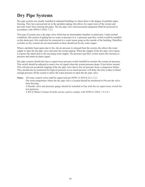
Dry Pipe Systems<br />
Dry pipe systems are usually installed in unheated buildings or where there is the danger of sprinkler pipes<br />
freezing. They have pressurized air in the sprinkler piping, this allows for supervision of the system and<br />
prevents water from entering the pipes. The dry pipe valve and associated equipment Shall be protected in<br />
accordance with NFPA13 2010, 7.2.5.<br />
Fig. 7<br />
TO WATER<br />
MOTOR GONG<br />
Dry Pipe Valve System<br />
Waterflow Alarm Installation<br />
RISER TO<br />
SPRINKLER HEADS<br />
This type of system uses a dry pipe valve which has an intermediate chamber or alarm port. Under normal<br />
conditions, this section of piping has no water or pressure in it. A pressure type flow switch would be installed<br />
on the alarm port, this could also be connected to a water motor gong on the outside of the building. Waterflow<br />
switches on dry systems do not need retards as there should not be any water surges.<br />
When a sprinkler head opens due to fire, the air pressure is released from the system, this allows the water<br />
supply to open the dry pipe valve and enter the system piping. When the clapper of the dry pipe valve opens,<br />
it exposes the alarm port to the incoming water supply. The pressure type flow switch senses this increase in<br />
pressure and sends an alarm signal.<br />
Dry pipe systems should also have a supervisory pressure switch installed to monitor the system air pressure.<br />
This switch should be adjusted to send a low air signal when the system pressure drops 10 psi below normal.<br />
This will prevent accidental tripping of the dry pipe valve due to low air pressure from a compressor failure.<br />
They should also be monitored for high air pressure as too much pressure will delay the time it takes to bleed<br />
enough pressure off the system to allow the water pressure to open the dry pipe valve.<br />
Notes: All water control valves shall be supervised per NFPA 13 2010 8.16.1.1.2.1.<br />
The room temperature where the dry pipe valve is located should be monitored to Prevent the valve<br />
from freezing.<br />
A bleeder valve and pressure gauge should be installed in line with the air supervisory switch for<br />
test purposes.<br />
A WCS (Water Column Switch) can be used to comply with NFPA13 2010, 7.2.5.4.1<br />
WATERFLOW<br />
SWITCH<br />
PS10-1<br />
PS10-2<br />
RBVS<br />
WATER BY-PASS<br />
TEST VALVE<br />
(CLOSED)<br />
PETCOCK<br />
(OPEN)<br />
CHECK<br />
BALL<br />
DRIP<br />
VALVE<br />
WATER<br />
PRESSURE<br />
GAUGE<br />
AIR SUPPLY<br />
VALVE<br />
(OPEN)<br />
CHECK<br />
AIR<br />
PRESSURE<br />
WATER LEVEL<br />
BVL BLEEDER<br />
TEST VALVE<br />
(OPEN)<br />
AIR PRESSURE<br />
SUPERVISORY<br />
PS40-1<br />
PS40-2<br />
AIR SUPPLY<br />
AIR<br />
PRESSURE<br />
GAUGE<br />
PRIMING<br />
CHAMBER<br />
SHUT-OFF<br />
VALVE<br />
(CLOSED)<br />
INTERMEDIATE<br />
CHAMBER<br />
DRAIN VALVE (CLOSED)<br />
TAMPER<br />
DEVICE<br />
OSYSU<br />
DRIP<br />
CUP<br />
OS & Y<br />
CONTROL<br />
VALVE<br />
(OPEN)<br />
CHECK<br />
Note:<br />
Per NFPA72 2010 23.8.5.10.4, there shall be<br />
no shut-off valve in line to a pressure type<br />
waterflow switch, unless the shut-off ball<br />
valve is electrically supervised with <strong>Potter</strong><br />
Model RBVS (Retrofit Ball Valve Switch).<br />
WATER PRESSURE<br />
FROM CITY MAINS<br />
DRAIN<br />
PIPE<br />
DWG# 8704200-4A<br />
26 27