Training Manual - Potter Electric Signal Company, LLC
Training Manual - Potter Electric Signal Company, LLC
Training Manual - Potter Electric Signal Company, LLC

You also want an ePaper? Increase the reach of your titles
YUMPU automatically turns print PDFs into web optimized ePapers that Google loves.
Fig. 10<br />
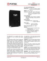
Valve Supervision (Tamper Switch)<br />
Selection Guide<br />
TYPE OF VALVE<br />
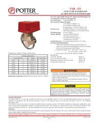
Installation of Waterflow Switches<br />
Read and follow the manufacturers instructions.<br />
Vane (Paddle) type: For use in wet pipe systems only!<br />
Vane type water flow switches can be installed in either vertical or horizontal sections of pipe. If they are<br />
installed in a horizontal section, they must be installed on the top half of the pipe. This is to prevent any debris<br />
in the pipe from falling into the throat area of the flow switch and affecting the paddle movement. They should<br />
never be installed on the bottom half of the pipe.<br />
OUTSIDE<br />
SCREW<br />
& YOKE<br />
(OS & Y)<br />
BUTTERFLY<br />
POST INDICATOR<br />
(PIV)<br />
(YARD OR WALL)<br />
BALL VALVE<br />
After shutting off the water to the system and draining it, drill the correct size hole for the flow switch. The hole<br />
should be de-burred and the inside of the pipe should be cleaned of any rust, scale or corrosion. Do not trim the<br />
paddle. The most likely area for a paddle to hang up is the area immediately upstream of the hole in the pipe,<br />
on the same side of the pipe as the hole. When water flows through the system, the paddle is pressed against the<br />
inside of the pipe.<br />
The flow switch should be centered in the pipe and the “U” bolt should be tightened evenly according to the<br />
manufacturer’s specifications. This will prevent the paddle from dragging on the inside of the pipe and prevent<br />
the flow switch from leaking.<br />
WALL<br />
When filling the system, first open any valves at the end of the system or branch lines. Slowly open the water<br />
supply valve, let the water flow out of the valves until it is flowing smoothly. This will prevent air from entering<br />
the system and help bleed any trapped air out of the system.<br />
Fig. 11<br />
COVER TAMPER SWITCH<br />
DO NOT LEAVE COVER OFF FOR<br />
EXTENDED PERIOD OF TIME<br />
OS & Y<br />
OUTSIDE SCREW<br />
& YOKE<br />
BUTTERFLY VALVE<br />
PIV<br />
POST INDICATOR VALVE<br />
WALL PIV<br />
WALL POST<br />
INDICATOR VALVE<br />
RBVS<br />
TIGHTEN NUTS<br />
ALTERNATELY<br />
OSYSU-1 ONE CONTACT<br />
OSYSU-2 TWO CONTACTS<br />
PCVS-1 ONE CONTACT<br />
PCVS-2 TWO CONTACTS<br />
DWG# 8704200-J1<br />
MOUNT ON PIPE SO<br />
ARROW ON SADDLE<br />
POINTS IN DIRECTION<br />
OF WATERFLOW<br />
ROLL PADDLE IN<br />
OPPOSITE DIRECTION<br />
OF WATERFLOW<br />
DIRECTION OF<br />
WATERFLOW<br />
DWG. #1146-1E<br />
30 31