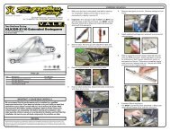
LTZ400 Dyna FS Ignition (Programmable)
LTZ400 Dyna FS Ignition (Programmable)
LTZ400 Dyna FS Ignition (Programmable)

Create successful ePaper yourself
Turn your PDF publications into a flip-book with our unique Google optimized e-Paper software.
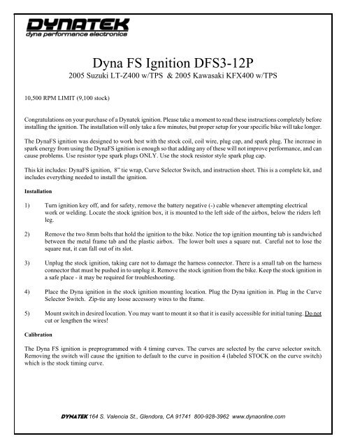
<strong>Dyna</strong> <strong>FS</strong> <strong>Ignition</strong> D<strong>FS</strong>3-12P<br />
2005 Suzuki LT-Z400 w/TPS & 2005 Kawasaki KFX400 w/TPS<br />
10,500 RPM LIMIT (9,100 stock)<br />
Congratulations on your purchase of a <strong>Dyna</strong>tek ignition. Please take a moment to read these instructions completely before<br />
installing the ignition. The installation will only take a few minutes, but proper setup for your specific bike will take longer.<br />
The <strong>Dyna</strong><strong>FS</strong> ignition was designed to work best with the stock coil, coil wire, plug cap, and spark plug. The increase in<br />
spark energy from using the <strong>Dyna</strong><strong>FS</strong> ignition is enough so that adding any of these will not improve performance, and can<br />
cause problems. Use resistor type spark plugs ONLY. Use the stock resistor style spark plug cap.<br />
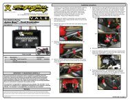
This kit includes: <strong>Dyna</strong><strong>FS</strong> ignition, 8” tie wrap, Curve Selector Switch, and instruction sheet. This is a complete kit, and<br />
includes everything needed to install the ignition.<br />
Installation<br />
1) Turn ignition key off, and for safety, remove the battery negative (-) cable whenever attempting electrical<br />
work or welding. Locate the stock ignition box, it is mounted to the left side of the airbox, below the riders left<br />
leg.<br />
2) Remove the two 8mm bolts that hold the ignition to the bike. Notice the top ignition mounting tab is sandwiched<br />
between the metal frame tab and the plastic airbox. The lower bolt uses a square nut. Careful not to lose the<br />
square nut, it can fall out of its slot.<br />
3) Unplug the stock ignition, taking care not to damage the harness connector. There is a small tab on the harness<br />
connector that must be pushed in to unplug it. Remove the stock ignition from the bike. Keep the stock ignition in<br />
a safe place - it may be required for troubleshooting.<br />
4) Place the <strong>Dyna</strong> ignition in the stock ignition mounting location. Plug the <strong>Dyna</strong> ignition in. Plug in the Curve<br />
Selector Switch. Zip-tie any loose accessory wires to the frame.<br />
5) Mount switch in desired location. You may want to mount it so that it is easily accessible for initial tuning. Do not<br />
cut or lengthen the wires!<br />
Calibration<br />
The <strong>Dyna</strong> <strong>FS</strong> ignition is preprogrammed with 4 timing curves. The curves are selected by the curve selector switch.<br />
Removing the switch will cause the ignition to default to the curve in position 4 (labeled STOCK on the curve switch)<br />
which is the stock timing curve.<br />
DYNATEK 164 S. Valencia St., Glendora, CA 91741 800-928-3962 www.dynaonline.com
Curve 4 is identical to the curve that came with the stock ignition module. The advance is based on throttle position and<br />
varies smoothly from Closed Throttle to WOT. Due to improved microprocessor control and significantly higher spark<br />
energy, the performance of this curve will be enhanced. A quicker throttle response and increased power over stock is still<br />
achieved with the stock ignition curve. For the other 3 timing curves, see the attached chart for the timing information.<br />
Use of this ignition may require rejetting of the carburetor to supply more fuel to maximize performance gains. If you are<br />
unsure of this tuning process, the services of a competent mechanic should be employed. Curve 4, the stock curve, is least<br />
likely to require any sort of jetting adjustment.<br />
Using the other curves may result in a lean misfire condition at high RPMs when the jetting is not properly set. Do not<br />
operate the engine in a lean condition for extended periods or damage may result.<br />
This ignition will allow the engine to rev to a higher RPM than what it has before. The rev limit is programmable from<br />
2000rpm to 14,000rpm. Stock rev limit is 9100rpm. The revlimit is pre-programmed to 10,500. Because the rev limit is<br />
increased, the performance limits of other engine parts (valvetrain for example) may be found. It may be necessary to<br />
replace these parts for best engine performance. Consult with an engine builder for answers on what works best for your<br />
engine.<br />
<strong>Programmable</strong> ignitions<br />
Lap-top/PC <strong>Programmable</strong> versions (suffixed with a P in the part number) require a separate programming kit to reprogram<br />
them. It is not supplied with the ignition. If the programmable ignition was not purchased directly from <strong>Dyna</strong>tek, the dealer<br />
may have programmed a custom set of ignition curves. The dealer should be consulted with any questions regarding the<br />
curves that are programmed into the ignition.<br />
The Launch RPM is programmable and can be wired to a separate clutch switch (not included) for a “two step/low side”<br />
launch limiter. See attached wiring diagram for installation.<br />
<strong>Programmable</strong> ignitions are shipped with additional leads coming out of the ignition. These leads allow the ignition to<br />
control other features. To program these features, follow the instructions in the programming kit.<br />
PURPLE – <strong>Programmable</strong> launch limiter. Ground this wire to activate (requires separate clutch switch)<br />
GREEN – Tachometer output, for a standard 12v, two pulse per rev aftermarket tach.<br />
BLUE – Optional 2-amp switch to ground, referenced as “RPM Switch 1” in PC Software.<br />
WHITE – Optional 2-amp switch to ground, referenced as “RPM Switch 2” in PC Software.<br />
The Blue & White 2-amp switches can be used to activate a solenoid or relay. Connect the relay with hot +12v wired to<br />
one side of the relay coil, and the other side connected to White or Blue. When the rpm activates the switch, it will be<br />
grounded inside the ignition box, causing current to flow through the relay coil. DO NOT connect any device which<br />
requires more than 2 Amps (Amps=Volts/Resistance). See attached wiring diagram for wiring the relay.<br />
Troubleshooting<br />
Troubleshooting the <strong>Dyna</strong> ignition is simple. If the bike will not start or run at all, reinstall the stock ignition. If this fixes<br />
the problem, then the <strong>Dyna</strong> ignition should be returned to <strong>Dyna</strong>tek for testing. If this does not fix the problem, then the<br />
problem is somewhere else on the bike. Follow the troubleshooting procedures outlined in your bike shop manual.<br />
If the bike runs, but poorly, put the stock ignition back on the bike. If this fixes the problem, reinstall the <strong>Dyna</strong> ignition. If<br />
you are using non stock plug wires, plug cap, ignition coil, spark plug, or stator, replace them with OEM units. Then follow<br />
the procedures in the calibration section to set the <strong>Dyna</strong> ignition up to work with your bike. If calibration doesn't fix the<br />
problem, the ignition should be returned for testing. If the problem persists when using the stock ignition then the problem<br />
is external to the <strong>Dyna</strong> ignition.<br />
2801201B REV. 9-5-08<br />
DYNATEK 164 S. Valencia St., Glendora, CA 91741 800-928-3962 www.dynaonline.com
WARNING:<br />
Installation of a grounded tether kill switch to the ignition coil signal will<br />
damage the CDI and void the warranty.<br />
12V DC-CDI (<strong>LTZ400</strong>/KFX400/etc.): Use a normally closed tether kill switch connected in series with the<br />
+12V input to the ignition. When the tether is removed, it should disconnect the +12V power to the ignition.<br />
<strong>LTZ400</strong>/KFX400 +12V POWER INPUT: BLACK/ORANGE at the ignition module.<br />
The RUN/STOP SWITCH is another +12V input into the ignition module. Either wire (ORANGE/WHITE or<br />
ORANGE) can be disconnected to remove +12V from the ignition.<br />
DYNATEK 164 S. Valencia St., Glendora, CA 91741 800-928-3962 www.dynaonline.com
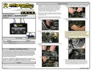
4-position connector for<br />
PC/Laptop programming<br />
DIRECT<br />
PLUG-IN<br />
3-position connector for<br />
Curve Selector Switch<br />
4 wires terminated with<br />
female bullet connectors<br />
PURPLE = Two-step/low-side Launch Rev Limiter, requires a seperate switch (not included). Ground this<br />
wire to activate the limiter. Use programming software to adjust the launch rpm.<br />
GREEN = Tach output, 2 pulse per rev, 12V<br />
BLUE = <strong>Programmable</strong> Speed Switch, 2 AMP MAX<br />
(referenced as "RPM Switch 1" in PC software)<br />
WHITE = <strong>Programmable</strong> Speed Switch, 2 AMP MAX<br />
(referenced as "RPM Switch 2" in PC software)<br />
NOTE1: White and Blue power switches can be programmed individually or together. Can be used to turn<br />
on a shift light, or activate a small solenoid, or switch a Bosch style relay for even heavier loads.<br />
NOTE2: The ignition will ground the White or Blue white inside the CDI when the pre-programmed RPM<br />
is achieved.<br />
DYNATEK 164 S. Valencia St., Glendora, CA 91741 800-928-3962 www.dynaonline.com
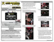
2005 DYNA <strong>FS</strong> / SUZUKI LT-Z400 QUADSPORT IGNITION CURVES<br />
CURVE2<br />
CURVE4<br />
STOCK WOT CURVE<br />
STOCK CLOSED<br />
THROTTLE CURVE<br />
CURVE1<br />
STOCK CURVE<br />
CURVE3<br />
RPM / 1000<br />
CURVE4 = STOCK ADVANCE<br />
(Chart includes the 10° base timing)<br />
IGNITION ADVANCE<br />
(CRANKSHAFT DEGREES)<br />
DYNATEK 164 S. Valencia St., Glendora, CA 91741 800-928-3962 www.dynaonline.com