LED Dimmer LED-04ECM-350
LED Dimmer LED-04ECM-350
LED Dimmer LED-04ECM-350

Create successful ePaper yourself
Turn your PDF publications into a flip-book with our unique Google optimized e-Paper software.
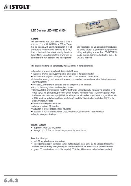
<strong>LED</strong> <strong>Dimmer</strong> <strong>LED</strong>-<strong>04ECM</strong>-<strong>350</strong><br />
General<br />
The <strong>LED</strong> dimmer has been developed to drive 4<br />
channels of up to 10, 1W <strong>LED</strong>´s at <strong>350</strong>mA. Therefore<br />
it is possible, with a dimming resolution of 16 bit<br />
(international resolution when driven via the ISYGLT<br />
bus), to dim the diodes without intensity deviations<br />
from 0-100%. Each channel of the dimmer can be<br />
calibrated for it own, absolute, time based parameters.<br />
This enables not just accurate dimming but also<br />
the simple creation of predenfined complex colour<br />
mixing and lighting scenes. The <strong>LED</strong>-<strong>04ECM</strong>-<strong>350</strong><br />
can be controlled either via the ISYGLT bus or the<br />
DMX-512 protocols.<br />
The following functions can be fulfilled by the <strong>LED</strong> dimmer in stand alone mode:<br />
• Calculation of ramp up times from 0.5 seconds to 12 hours<br />
• True colour dimming based upon the colour temperature of the total illumination<br />
• Colour temperature (colour mixing) for 2 areas with 1x cool white and 1x warm white<br />
• Independent ramping from the current true value to a prescribed command value with a defined momentum<br />
(currently optional)<br />
• Feed back „Command value achieved“ after the completion of the operation<br />
• Stop function during a time based ramping operation<br />
• OVERSAMPLING error correction. The OVERSAMPLING function basically increases the resolution of the<br />
output signal. The generated output consists of an interpolar transitional value. This is most apparent when<br />
the low resolution command input (8 bit) is forced to perform a immediate jump, the output signal follows with<br />
a 16 bit resolution and effectively blocks any (integral) instability. This is function labelled as „SOFT“ in the<br />
programming source code.<br />
• Execution of blinking/strobe functions<br />
• Adaption to various <strong>LED</strong> modules<br />
• Calculation of defined and pre-empted waveforms<br />
• Calculation of the min and max values for each channel to optimise the full 16 bit bandwidth<br />
• Complex emergency functions<br />
Inputs / Outputs<br />
• 4 outputs for power <strong>LED</strong> 1W, <strong>350</strong>mA<br />
• 1 average input „E“. The function can be parametred by each channel.<br />
Function displays<br />
• 1 red <strong>LED</strong> signalise the operating voltage<br />
• 1 yellow <strong>LED</strong> signalise by permanent shining that the ISYGLT bus is active but the address of the dimmer<br />
won´t be detected and by steady flashing the communication with the master module (address detected)<br />
• 1 green <strong>LED</strong> indicates the control of the outputs (<strong>LED</strong> flashes, till the desired value has been reached).<br />
6.4.2
Connections<br />
• 2 connections for the subnet (BUS A and B, RS-485)<br />
• 2 connections for the operating voltage (Ub, 0V BUS components)<br />
• 1 connection for the average input<br />
• 1 connection for external <strong>LED</strong> power supply<br />
• 3 connections anode (+) power <strong>LED</strong> (internal jumpered)<br />
• 4 connections cathode (-) power <strong>LED</strong><br />
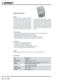
Design<br />
• plastic casing<br />
DIP switches<br />
• DMX-512 mode with delay<br />
(Oversampling of the 8 bit to 16 bit values)<br />
Default 50ms, by parameterisation setable from<br />
10ms up to 1s, such as „Soft“<br />
Switch Function<br />
DIP 1 protocol 1 OFF<br />
DIP 2 protocol 2 ON<br />
DIP 3 reserve OFF<br />
DIP 4 address bit 7 module address<br />
(highest bit)<br />
DIP 5 address bit 6 module address<br />
DIP 6 address bit 5 module address<br />
DIP 7 address bit 4 module address<br />
DIP 8 address bit 3 module address<br />
DIP 9 address bit 2 module address<br />
DIP 10 address bit 1 module address<br />
(lowest bit)<br />
• ISYGLT mode<br />
Switch Function<br />
DIP 1 protocol 1 OFF<br />
DIP 2 protovol 2 OFF<br />
DIP 3 reserve OFF<br />
DIP 4 address bit 7 module adress<br />
(highest bit)<br />
DIP 5 address bit 6 module address<br />
DIP 6 address bit 5 module address<br />
DIP 7 address bit 4 module address<br />
DIP 8 address bit 3 module address<br />
DIP 9 address bit 2 module address<br />
DIP 10 address bit 1 module address<br />
(lowest bit)<br />
With the DIP switches 4 to 10 the DMX addresses<br />
can be committed. The adjusted address, multiplied<br />
by 4 and adds up to one, conforms the first of four<br />
successive DMX addresses.<br />
- address 0, 0000000 = DMX 1, 2, 3 and 4<br />
- address 1, 0000001 = DMX 5, 6, 7 and 8<br />
- address 127, 1111111 = DMX 509, 510, 511 and<br />
512<br />
6.4.3
Parameterisation<br />
The ISYGLT ProgrammDesigner contains manifold parameter options.<br />
• Operating modes<br />
- 4 single channels<br />
- RGB + 1 single channel, red, green, blue such as a independent single channel<br />
- RGBW, red, green, blue and white<br />
- Colour temperature control (day light emulation)<br />
- Online function shift via special time constant on channel 2<br />
• Setting several dimm curves<br />
• Minimal and Maximal values<br />
Technical data<br />
Type<br />
<strong>LED</strong>-<strong>04ECM</strong>-<strong>350</strong><br />
Art. No. 80027042<br />
Operating voltage<br />
12V to 24V for BUS interface<br />
12V to 48V DC impulse stabil for Power <strong>LED</strong>´s<br />
Current consumption<br />
max. 400mA per <strong>LED</strong> circuit, BUS interface 10mA<br />
Output power Variant 1:<br />
4 circuits with each <strong>350</strong>mA for 10x <strong>LED</strong> 1W per circuit.<br />
commendation for external power supply:<br />
up to 2 <strong>LED</strong> 12V DC<br />
up to 4 <strong>LED</strong> 24V DC<br />
5-10 <strong>LED</strong> max. 48V DC<br />
ripple current 1,6A<br />
BUS control<br />
Line length feed to the <strong>LED</strong>-<br />
<strong>Dimmer</strong><br />
Line length <strong>LED</strong>-<strong>Dimmer</strong><br />
to the last <strong>LED</strong><br />
Output<br />
Mounting<br />
Subnet (RS-485)<br />
Dimensions<br />
Weight<br />
Connection<br />
maximal environmental temperature<br />
Storage temperature<br />
Humidity<br />
Protection grade<br />
Immunity<br />
Noise emission<br />
CE sign<br />
Variant 2:<br />
4 circuits up to <strong>350</strong>mA for 0-48V<br />
(<strong>LED</strong> stripes with integrated current setting)<br />
ISYGLT / DMX-512 (further on request)<br />
Max. 40m / 1.5mm 2<br />
Max. 20m / at 1W <strong>LED</strong>s 0.50 – 1.5mm 2<br />
16 bit resolution<br />
Plastic casing<br />
max. 5,6V limited by Z-diodes<br />
LxBxH 232x54x34mm<br />
210g<br />
Screw terminals 1,5mm²<br />
+45°C<br />
-25...+70°C<br />
0 ...85 % r.F. non condensing<br />
IP20<br />
Conformal EN61000-6-1, EN61000-6-2<br />
Conformal EN55015<br />
yes<br />
6.4.4
Terminal assignment<br />
≅ Ub<br />
≅ Ub<br />
0V<br />
0V<br />
A<br />
A<br />
B<br />
B<br />
E1<br />
operating voltage (BUS components)<br />
operating voltage (BUS components)<br />
operating voltage (BUS components)<br />
operating voltage (BUS components)<br />
Subnet (BUS A, RS-485)<br />
Subnet (BUS A, RS-485)<br />
Subnet (BUS B, RS-485)<br />
Subnet (BUS B, RS-485)<br />
Input for average mode<br />
+Vin volgate input + for <strong>LED</strong> supply<br />
GND volgate input - for <strong>LED</strong> supply<br />
An.C Common anode (+) of the power <strong>LED</strong><br />
An.C Common anode (+) of the power <strong>LED</strong><br />
An.C Common anode (+) of the power <strong>LED</strong><br />
Ka.1 Cathode (-) for power <strong>LED</strong> channel 1<br />
Ka.2 Cathode (-) for power <strong>LED</strong> channel 2<br />
Ka.3 Cathode (-) for power <strong>LED</strong> channel 3<br />
Ka.4 Cathode (-) for power <strong>LED</strong> channel 4<br />
View<br />
Height:<br />
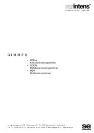
Wiring diagram<br />
+24V<br />
0V=<br />
BUS-A<br />
BUS-B<br />
ISYGLT-BUS<br />
Havarie ON<br />
Ub<br />
0V<br />
BUS A<br />
BUS B<br />
OFF<br />
ON<br />
1 2 3 4 5 6 7 8 910<br />
Art.-Nr.: 80027042<br />
1-3=OFF BUS-adress<br />
ISYGLT-<strong>LED</strong>-<strong>04ECM</strong>-<strong>350</strong><br />
constant current<br />
4 x <strong>350</strong>mA<br />
+Vin<br />
GND<br />
An.C<br />
AN.C<br />
An.C<br />
Ka.1<br />
Ka.2<br />
Ka.3<br />
E1<br />
Ka.4<br />
12-48V DC<br />
external power supply<br />
(ripple current 1,6A)<br />
+<br />
-<br />
2<br />
Dimmchannel 1 e.g. red<br />
Dimmchannel 2 e.g. green<br />
Dimmchannel 3 e.g. blue<br />
Dimmchannel 4 e.g. white<br />
1-10 Power-<strong>LED</strong> 1W (<strong>350</strong>mA)<br />
6.4.5