Compact-Controller CC-01
Compact-Controller CC-01
Compact-Controller CC-01

You also want an ePaper? Increase the reach of your titles
YUMPU automatically turns print PDFs into web optimized ePapers that Google loves.
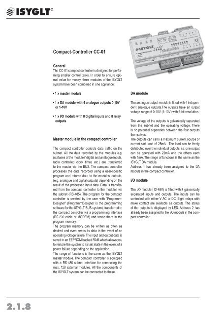
<strong>Compact</strong>-<strong>Controller</strong> <strong>CC</strong>-<strong>01</strong><br />
General<br />
The <strong>CC</strong>-<strong>01</strong> compact controller is designed for performing<br />
smaller control tasks. In order to ensure optimal<br />
value for money, three modules of the ISYGLT<br />
system have been combined in one appliance:<br />
• 1 x master module<br />
• 1 x DA module with 4 analogue outputs 0-10V<br />
or 1-10V<br />
• 1 x I/O module with 8 digital inputs and 8 relay<br />
outputs<br />
Master module in the compact controller<br />
The compact controller controls data traffic on the<br />
subnet. All the data recorded by the modules e.g.<br />
(statuses of the modules’ digital and analogue inputs,<br />
radio controlled clock times etc.) are transferred<br />
to the master via the BUS. The compact controller<br />
processes the data recorded using a user-specific<br />
program and returns data to the modules’ outputs,<br />
(e.g. analogue and digital outputs) depending on the<br />
result of the processed input data. Data is transferred<br />
from the compact controller to the modules via<br />
the subnet (RS-485). The program for the compact<br />
controller is created by the user with “Programm-<br />
Designer” (ProgrammDesigner is the programming<br />
software for the ISYGLT BUS system), transferred to<br />
the compact controller via a programming interface<br />
(RS-232 cable or MODEM) and saved there in the<br />
program memory.<br />
The program memory can be written as often as<br />
desired and even keeps its data in the event of an<br />
operating voltage failure. The input and output data is<br />
saved in an EEPROM backed RAM which allows you<br />
to restore the system to its last state in the event of a<br />
power failure depending on the application.<br />
The range of functions is the same as the ISYGLT<br />
master module. The compact controller is equipped<br />
with a RS-485 subnet interface for connecting the<br />
max. 128 external modules. All the components of<br />
the ISYGLT system can be connected to these.<br />
DA module<br />
The analogue output module is fitted with 4 independent<br />
analogue outputs.The outputs have an output<br />
voltage range of 0-10V (1-10V) with 8-bit resolution.<br />
The voltage of the outputs is galvanically separated<br />
from the subnet and the operating voltage. There<br />
is no potential separation between the four outputs<br />
themselves.<br />
The outputs can carry a maximum current source or<br />
current sink load of 25mA. The load can be freely<br />
distributed over the individual outputs, i.e. one output<br />
can be operated with 22mA and the others each<br />
with 1mA. The range of functions is the same as the<br />
ISYGLT DA module.<br />
Address 1 has already been assigned to the DA<br />
module in the compact controller.<br />
I/O module<br />
The I/O module (12-48V) is fitted with 8 galvanically<br />
separated inputs and outputs. The inputs can be<br />
controlled with either V AC or DC. Eight relays with<br />
make contact are available as outputs. The status<br />
of the outputs is displayed by LED. Address 2 has<br />
already been assigned to the I/O module in the compact<br />
controller.<br />
2.1.8
In- / Outputs<br />
• 8 relay outputs max. 230V / 10A, 2 contacts each on a common root node with 10A load capacity<br />
• 8 optical coupler inputs 12-48V<br />
• 4 analogue outputs 0-10V (1-10V)<br />
• RS-232 interface for MODEM/PC connection for programming<br />
Functions displays<br />
• 1 red „power“ LED indicates the operating voltage.<br />
• 1 red „prog.“ LED indicates that programs are being transfered from the PC/modem to the compact controller<br />
and vice versa via the programming intervace<br />
• 1 green „Betrieb“ LED indicates the processor function. Steady flashing means „system ok, however no<br />
DCF-77 time received“. 2x short flashes followed by a pause means „system ok and valid DCF-77 time received.<br />
• 1 flashing yellow „Bus“ LED indicates trouble-free data transfer on the subnet<br />
• 8 green „A1...A8“ LED signalise the current output status. The output relay is activated when the respective<br />
LED lights up.<br />
Connections<br />
• 1 connection for the subnet (BUS A and B, RS-485)<br />
• 1 connection for the operating voltage (Ub, 0V)<br />
• 8 outputs (two each on a common connection)<br />
• 8 inputs (on a common reference terminal)<br />
• 2 P-COM connections<br />
• 4 analogue outputs<br />
• 1 connection for RS-232<br />
• 1 SUB-D RS-232 (behind cover)<br />
• 4 GND connections<br />
Design<br />
• Light grey plastic casing, can be snapped onto 35mm DIN-rail mounting 9 TE separating units<br />
Special functions DIP switch (behind cover)<br />
The DIP switches can be used for operating the outputs without a program in an emergency<br />
-Switch 1 = ON the analogue outputs emit a voltage of10V.<br />
-Switch 2 = ON All output relays are activated<br />
2.1.9
Technical data<br />
Type<br />
<strong>Compact</strong>-<strong>Controller</strong> <strong>CC</strong>-<strong>01</strong><br />
Art.-Nr. 80<strong>01</strong>6000<br />
Operating voltage<br />
17V bis 35V DC bzw. 17V bis 27V AC<br />
Power consumption<br />
When analogue outputs are at full load and all relays are activated<br />
17V DC 380mA, 24V DC 270mA, 35V DC 180mA<br />
17V AC 500mA, 24V AC 330mA, 27V AC 300mA<br />
Inputs<br />
Input current per input 5mA at 24V<br />
Relay outputs<br />
Caution: common root node! Relay contact 250V Load capacity:<br />
non-inductive 10A<br />
bulbs 10A<br />
Fluorescent lamp uncompensated 6A<br />
Fluorescent lamp compensated 4A<br />
LV halogen via transformer 10A<br />
1-phase-motor 0,55kW<br />
Electronic ballast´s manufacturer-specific starting current 100A < 20ms<br />
The starting current of electronic ballasts is up to 100 times the nominal<br />
current!!<br />
Analogue outputs<br />
Output voltage 4 analogue channels 8 bit resolution 0-10V (1-10V)<br />
output voltage max. 25mA all 4 outputs together as current source or current<br />
sink.<br />
Isulation voltage<br />
300V (ISYGLT-Bus / Analogue outputs)<br />
Interface 1<br />
RS-485 Subnet max. 5,6V limited by Z-diodes<br />
Interface 2<br />
RS-232 interface for PC / Modem connection<br />
Program memory<br />
64 KByte (EPROM)<br />
Program memory for user program: 8 KByte optional 16 KByte (EEPROM)<br />
programmable<br />
Data memory 1:<br />
32 KByte (RAM) battery backed, non-volatile<br />
Data memory 2:<br />
8 KByte (EEPROM) for switching times, non-volatile<br />
Data memory 3:<br />
8 KByte (EEPROM) for lighting, non-volatile<br />
Dimensions BxHxT 160x90x59mm (9 T)<br />
Weight<br />
500 g<br />
Connection<br />
Screw terminals 2,5mm² plug-in<br />
Operating voltage<br />
-10°C...+50°C<br />
Storage temperature<br />
-25°C...+70°C<br />
Humidity<br />
0...85 % r.F. non condensing<br />
Protection class IP 30<br />
ESD immunity<br />
Category 3 according to IEC-1000-4-2 (4 kV static)<br />
EMC immunity<br />
Use in typical industrial enviroment. Category 3 according to IEC-1000-4-4<br />
(Test was carried out within a whole system)<br />
CE mark<br />
yes<br />
2.1.10
Terminal assignment<br />
Terminals Designation<br />
@ Ub<br />
Operating voltage<br />
0V<br />
0V operating voltage<br />
A<br />
Subnet (BUS A, RS-485)<br />
B<br />
Subnet (BUS B, RS-485)<br />
Sh.<br />
Remains free<br />
C.5 Common für E1-E8<br />
E1 Input 1<br />
E2 Input 2<br />
E3 Input 3<br />
E4 Input 4<br />
E5 Input 5<br />
E6 Input 6<br />
E7 Input 7<br />
E8 Input 8<br />
C.1 Common für A1/A2<br />
A1 Output 1<br />
A2 Output 2<br />
C.2 Common für A3/A4<br />
A3 Output 3<br />
A4 Output 4<br />
C.3 Common für A5/A6<br />
A5 Output 5<br />
A6 Output 6<br />
C.4 Common für A7/A8<br />
A7 Output 7<br />
A8 Output 8<br />
GND<br />
Programming and visualization interface<br />
(RS-232) mass<br />
RxD<br />
Programming and visualization interface<br />
(RS-232) RxD received line<br />
TxD<br />
Programming and visualization interface<br />
(RS-232) TxD transmitter line<br />
DTR<br />
Programming and visualization interface<br />
(RS-232) DTR status line<br />
GND<br />
Programming and visualization interface<br />
(RS-232) mass<br />
UA1 Analogue output 1<br />
GND GND to analogue output 1<br />
UA2<br />
Analogue output2<br />
GND GND to analogue output 2<br />
UA3 Analogue output 3<br />
GND GND to analogue output 3<br />
UA4 Analogue output 4<br />
GND GND to Analogue output 4<br />
The GND of the UA1-4 are connected to each other<br />
2.1.11
2.1.12<br />
View
Wiring diagram<br />
+24V<br />
0V=<br />
BUS-A<br />
BUS-B<br />
ISYGLT-compact-controller <strong>CC</strong>-<strong>01</strong><br />
Art.-Nr.: 80<strong>01</strong>6000<br />
max. 230V/10A per group of contacts<br />
address f. DA-outputs AA1.1 -> AA1.4<br />
address f. IO-outputs A2.1 -> A2.8<br />
address f. IO-inputs E2.1 -> E2.8<br />
dispatching not changeable<br />
4 analog outputs 0(1)-10V,totaly max. 25mA<br />
N<br />
N<br />
L<br />
L<br />
L<br />
Ub<br />
A1<br />
A2<br />
C.1<br />
A3<br />
A4<br />
C.2<br />
A5<br />
A6<br />
C.3<br />
A7<br />
A8<br />
C.4<br />
UA1<br />
GND<br />
UA2<br />
GND<br />
UA3<br />
GND<br />
UA4<br />
GND<br />
N<br />
0V<br />
BUS A<br />
BUS B<br />
C.5<br />
E1<br />
E2<br />
E3<br />
E4<br />
E5<br />
E6<br />
E7<br />
E8<br />
N<br />
N<br />
N<br />
M<br />
net<br />
230V AC<br />
Dimmer<br />
+ -<br />
0-10V<br />
net + -<br />
230V AC 1-10V<br />
EVG<br />
controll.<br />
N<br />
2.1.13