Used Parameters - STÃBER ANTRIEBSTECHNIK GmbH + Co. KG
Used Parameters - STÃBER ANTRIEBSTECHNIK GmbH + Co. KG
Used Parameters - STÃBER ANTRIEBSTECHNIK GmbH + Co. KG

You also want an ePaper? Increase the reach of your titles
YUMPU automatically turns print PDFs into web optimized ePapers that Google loves.
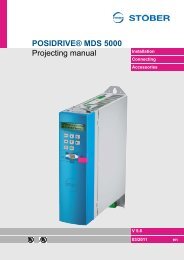
APPLICATION<br />
Fast Reference Value<br />
5 th Generation of STÖBER Inverters<br />
FUNCTIONS<br />
DETAILS<br />
PARAMETER<br />
from V 5.6-D<br />
11/2011 EN
STÖBER <strong>ANTRIEBSTECHNIK</strong><br />
Table of <strong>Co</strong>ntents<br />
Fast Reference Value<br />
i<br />
Table of <strong>Co</strong>ntents<br />
1. Notes on Safetey .................................................... 1<br />
1.1 Software ................................................................................. 6<br />
1.2 Presentation of notes on safety ……....................................... 7<br />
2. Function Description ……...................................... 8<br />
2.1 Block Circuit Diagram ….......................................................... 8<br />
2.2 Interface ………....................................................................... 9<br />
2.2.1 Input Signals ……………………............................................... 10<br />
2.2.2 Output Signals ……………………............................................ 10<br />
2.2.3 Process Data Imaging ……..……………….............................. 11<br />
2.3 Assistant for Parameter Entry …………................................... 12<br />
3. Details ………………………..................................... 13<br />
3.1 Speed <strong>Co</strong>ntroller …………………………………....................... 13<br />
3.2 Local Operation ………………….............................................. 14<br />
3.3 A45 Quick Stop End ……………………................................... 15<br />
3.4 EMERGENCY OFF Activation …............................................. 16<br />
3.5 Torque Limit ………….……...................................................... 17<br />
3.6 Brake Activation<br />
(only for Application Fast Ref. Value with Brake Activation) .... 18<br />
3.7 Analog Inputs/Outputs ……….................................................. 19<br />
3.7.1 Analog Inputs ………….…….................................................... 19<br />
3.7.2 Analog Outputs ........................................................................ 19<br />
3.8 Application Events ……………................................................. 20<br />
3.9 <strong>Co</strong>mmunication with CAN ……………………………………..… 20<br />
3.10 <strong>Co</strong>mmunication with PROFIBUS ……………………………….. 20<br />
3.11 <strong>Co</strong>mmunication with EtherCAT …………………………………. 21<br />
3.12 <strong>Co</strong>mmunication with PROFINET ………………………………. 21<br />
3.13 Mapping …………………….…………………………………….. 21<br />
4. <strong>Used</strong> <strong>Parameters</strong> ……………………….................... 22<br />
4.1 Parameter Legend …………………………………................... 22<br />
4.2 Parameter List …………………............................................... 22<br />
www.stoeber.de<br />
ID 441727.02
STÖBER <strong>ANTRIEBSTECHNIK</strong><br />
Table of <strong>Co</strong>ntents<br />
Fast Reference Value<br />
i<br />
- This page was purposely left blank -<br />
www.stoeber.de<br />
ID 441727.02
STÖBER <strong>ANTRIEBSTECHNIK</strong><br />
Notes on Safety<br />
Fast Reference Value<br />
01<br />
1 Notes on Safety<br />
When in operation, inverters from STÖBER <strong>ANTRIEBSTECHNIK</strong> <strong>GmbH</strong> + <strong>Co</strong>.<br />
<strong>KG</strong> may have energized or rotating parts depending on their protection rating.<br />
Surfaces may heat up. For these reasons, comply with the following:<br />
• The safety notes listed in the following sections and points<br />
• The technical rules and regulations<br />
In addition, always read the mounting instructions and the short commissioning<br />
instructions.<br />
STÖBER <strong>ANTRIEBSTECHNIK</strong> <strong>GmbH</strong> + <strong>Co</strong>. <strong>KG</strong> accepts no liability for<br />
damages caused by non-adherence to the instructions or applicable<br />
regulations. Subject to technical changes to improve the devices without prior<br />
notice.<br />
This documentation is purely a product description. It does not represent<br />
promised properties in the sense of warranty law.<br />
<strong>Co</strong>mponent part of the product<br />
The technical documentation is a component part of a product.<br />
• Since the technical documentation contains important information, always<br />
keep it handy in the vicinity of the device until the machine is disposed of.<br />
• If the product is sold, disposed of, or rented out, always include the<br />
technical documentation with the product.<br />
Operation in accordance with its intended use<br />
In the sense of DIN EN 50178 (previously VDE 0160), the POSIDRIVE ®<br />
FDS 5000 and MDS 5000 and the POSIDYN ® SDS 5000 model series<br />
represent the electrical equipment of power electronics for the control of power<br />
flow in high-voltage current systems. They are designed exclusively to power:<br />
• Servo motors (MDS 5000, SDS 5000)<br />
• Asynchronous motors (FDS 5000, MDS 5000 and SDS 5000)<br />
Operation for purposes other than the intended use include the connection of<br />
other electrical loads!<br />
Before the manufacturer is allowed to put a machine on the market, he must<br />
have a danger analysis prepared as per machine guideline 98/37/EG. This<br />
analysis establishes the dangers connected with the use of the machine. The<br />
danger analysis is a multi-stage, iterative process. Since this documentation<br />
cannot begin to provide sufficient insight into the machine guidelines, please<br />
carefully study the latest standards and legal situation yourself. After the drive<br />
controller has been installed in machines, it cannot be commissioned until it<br />
has been determined that the machine complies with the regulations of EG<br />
guideline 98/37/EG.<br />
www.stoeber.de<br />
ID 441727.02<br />
1
Notes on Safety<br />
01<br />
Fast Reference Value<br />
STÖBER <strong>ANTRIEBSTECHNIK</strong><br />
Ambient conditions<br />
Model series POSIDRIVE ® FDS 5000 and MDS 5000 and POSIDYN ®<br />
SDS 5000 are products of the restricted sales class as described in IEC 61800-<br />
3. This product may cause high-frequency interference in residential zones and<br />
the user may be asked to take suitable measures.<br />
The inverters are not designed for use in public low-voltage networks which<br />
power residential areas. High-frequency interference must be expected when<br />
the inverters are used in such a network.<br />
The inverters are only intended for use in TN networks.<br />
The inverters are only designed for use on supply current networks which can<br />
delivery at the most a maximum of symmetrical rated short circuit current at<br />
480 Volts as per the following table:<br />
Max. symmetrical rated short circuit<br />
Device family Size<br />
current<br />
FDS 5000,<br />
MDS 5000,<br />
SDS 5000<br />
BG 0 and<br />
BG 1<br />
5000 A<br />
MDS 5000<br />
BG 2<br />
5000 A<br />
SDS 5000 BG 3 10000 A<br />
Install the inverter in a switching cabinet in which the permissible maximum<br />
surrounding air temperature is not exceeded (see mounting instructions).<br />
The following applications are prohibited:<br />
• Use in potentially explosive areas<br />
• Use in environments with harmful substances as per EN 60721 (e.g., oils,<br />
acids, gases, fumes, powders, irradiation)<br />
• Use with mechanical vibration and impact stresses which exceed the<br />
information in the technical data of the mounting instructions<br />
Implementation of the following applications is only permitted when STÖBER<br />
<strong>ANTRIEBSTECHNIK</strong> <strong>GmbH</strong> + <strong>Co</strong>. <strong>KG</strong> has been contacted first for permission:<br />
• Use in non-stationary applications<br />
Qualified personnel<br />
Since the drive controllers of the model series POSIDRIVE ® FDS 5000,<br />
POSIDRIVE ® MDS 5000 and POSIDYN ® SDS 5000 may harbor residual risks,<br />
all configuration, transportation, installation and commissioning tasks including<br />
operation and disposal may only be performed by trained personnel who are<br />
aware of the possible risks.<br />
www.stoeber.de<br />
ID 441727.02<br />
2
Notes on Safety<br />
01<br />
Fast Reference Value<br />
STÖBER <strong>ANTRIEBSTECHNIK</strong><br />
Personnel must have the qualifications required for the job. The following table<br />
lists examples of occupational qualifications for the jobs:<br />
Activity<br />
Possible occupational qualifications<br />
Transportation and storage Worker skilled in storage logistics or<br />
comparable training<br />
<strong>Co</strong>nfiguration<br />
• Graduate engineer (electrotechnology<br />
or electrical power<br />
technology)<br />
• Technician (m/f) (electro-technology)<br />
Installation and connection Electronics technician (m/f)<br />
<strong>Co</strong>mmissioning (of a standard<br />
application)<br />
Programming<br />
Operation<br />
Disposal<br />
• Technician (m/f) (electro-technology)<br />
• Master electro technician (m/f)<br />
Graduate engineer (electro-technology or<br />
electrical power technology)<br />
• Technician (m/f) (electro-technology)<br />
• Master electro technician (m/f)<br />
Electronics technician (m/f)<br />
In addition, the valid regulations, the legal requirements, the reference books,<br />
this technical documentation and, in particular, the safety information contained<br />
therein must be carefully:<br />
• read<br />
• understood and<br />
• complied with.<br />
Transportation and storage<br />
Immediately upon receipt, examine the delivery for any transportation<br />
damages. Immediately inform the transportation company of any damages. If<br />
damages are found, do not commission the product.<br />
If the device is not to be installed immediately, store it in a dry, dust-free room.<br />
Please see the mounting instructions for how to commission an inverter after it<br />
has been in storage for a year or longer.<br />
Installation and connection<br />
Installation and connection work are only permitted after the device has been<br />
isolated from the power!<br />
The accessory installation instructions allow the following actions during the<br />
installation of accessories:<br />
• The housing of the MDS 5000, SDS 5000 and FDS 5000 in the upper slot<br />
can be opened.<br />
• The housing of the MDS 5000 and SDS 5000 in the bottom slot can be<br />
opened.<br />
Opening the housing in another place or for other purposes is not permitted.<br />
www.stoeber.de<br />
ID 441727.02<br />
3
STÖBER <strong>ANTRIEBSTECHNIK</strong><br />
Notes on Safety<br />
Fast Reference Value<br />
01<br />
Use only copper lines. For the line cross sections to be used, see table 310-16<br />
of the NEC standard for 60 o C or 75 o C.<br />
Protect the device from falling parts (pieces of wire, leads, metal parts, and so<br />
on) during installation or other tasks in the switching cabinet. Parts with conductive<br />
properties inside the inverter can cause short circuits or device failure.<br />
The motor must have an integrated temperature monitor with basic isolation in<br />
acc. with EN 61800-5-1 or external motor overload protection must be used.<br />
The permissible protection class is protective ground. Operation is not<br />
permitted unless the protective conductor is connected in accordance with the<br />
regulations.<br />
<strong>Co</strong>mply with the applicable instructions for installation and commissioning of<br />
motor and brakes.<br />
<strong>Co</strong>mmissioning, operation and service<br />
Remove additional coverings before commissioning so that the device cannot<br />
overheat. During installation, provide the free spaces specified in the mounting<br />
instructions to prevent the inverter from overheating.<br />
The housing of the drive controller must be closed before you turn on the<br />
supply voltage. When the supply voltage is on, dangerous voltages can be<br />
present on the connection terminals and the cables and motor terminals<br />
connected to them. Remember that the device is not necessarily de-energized<br />
after all indicators have gone off.<br />
When network voltage is applied, the following are prohibited:<br />
• Opening the housing<br />
• <strong>Co</strong>nnecting or disconnecting the connection terminals<br />
• Installing accessories<br />
Proceed as shown below to perform these tasks:<br />
1. Disable the enable (X1).<br />
2. Turn off the supply voltage (power pack and controller power supply<br />
as well as any auxiliary voltages for encoder, brake, etc.).<br />
3. Protect the supply voltages from being turned on again.<br />
4. Wait 5 minutes (time the DC link capacitors need to discharge).<br />
5. Determine isolation from the voltage.<br />
6. Short circuit the network input and ground it.<br />
7. <strong>Co</strong>ver the adjacent, voltage-carrying parts.<br />
You can then start your work on the drive controller.<br />
Repairs may only be performed by STÖBER <strong>ANTRIEBSTECHNIK</strong> <strong>GmbH</strong> +<br />
<strong>Co</strong>. <strong>KG</strong>.<br />
Send defective devices together with a fault description to:<br />
STÖBER <strong>ANTRIEBSTECHNIK</strong> <strong>GmbH</strong> + <strong>Co</strong>. <strong>KG</strong><br />
Abteilung VS-EL<br />
Kieselbronner Str. 12<br />
75177 Pforzheim<br />
GERMANY<br />
www.stoeber.de<br />
ID 441727.02<br />
4
STÖBER <strong>ANTRIEBSTECHNIK</strong><br />
Notes on Safety<br />
Fast Reference Value<br />
01<br />
Disposal<br />
Please comply with the latest national and regional regulations!<br />
Dispose of the individual parts separately depending on their nature and<br />
currently valid regulations such as, for example:<br />
• Electronic scrap (PCBs)<br />
• Plastic<br />
• Sheet metal<br />
• <strong>Co</strong>pper<br />
• Aluminum<br />
Residual dangers<br />
The connected motor can be damaged with certain settings of drive controllers.<br />
• Longer operation against an applied motor halting brake<br />
• Longer operation of self-cooled motors at slow speeds<br />
Drives can reach dangerous excess speeds (e.g., setting of high output<br />
frequencies for motors and motor settings which are unsuitable for this).<br />
Secure the drive accordingly.<br />
www.stoeber.de<br />
ID 441727.02<br />
5
STÖBER <strong>ANTRIEBSTECHNIK</strong><br />
Notes on Safety<br />
Fast Reference Value<br />
01<br />
1.1 Software<br />
Using the POSITool software<br />
The POSITool software package can be used to select the application and<br />
adjust the parameters and signal monitoring of the 5th generation of STÖBER<br />
inverters. The functionality is specified by selecting an application and<br />
transmitting these data to an inverter.<br />
The program is the property of STÖBER <strong>ANTRIEBSTECHNIK</strong> <strong>GmbH</strong> + <strong>Co</strong>. <strong>KG</strong><br />
and is copyrighted. The program is licensed for the user.<br />
The software is only provided in machine-readable form.<br />
STÖBER <strong>ANTRIEBSTECHNIK</strong> <strong>GmbH</strong> + <strong>Co</strong>. <strong>KG</strong> gives the customer a nonexclusive<br />
right to use the program (license) provided it has been legitimately<br />
obtained.<br />
The customer is authorized to use the program for the above activities and<br />
functions and to make copies of the program, including a backup copy for<br />
support of this use, and to install same.<br />
The conditions of this license apply to each copy. The customer promises to<br />
affix the copyright notation to each copy of the program and all other property<br />
notations.<br />
The customer is not authorized to use, copy, change or pass on/transmit the<br />
program for purposes other than those in these regulations. The customer is<br />
also not authorized to convert the program (i.e., reverse assembly, reverse<br />
compilation) or to compile it in any other way. The customer is also not<br />
authorized to issue sublicenses for the program, or to rent or lease it out.<br />
Product maintenance<br />
The obligation to maintain refers to the two latest program versions created by<br />
STÖBER <strong>ANTRIEBSTECHNIK</strong> <strong>GmbH</strong> + <strong>Co</strong>. <strong>KG</strong> and approved for use.<br />
STÖBER <strong>ANTRIEBSTECHNIK</strong> <strong>GmbH</strong> + <strong>Co</strong>. <strong>KG</strong> will either correct program<br />
errors or will provide the customer with a new program version. This choice will<br />
be made by STÖBER <strong>ANTRIEBSTECHNIK</strong> <strong>GmbH</strong> + <strong>Co</strong>. <strong>KG</strong>. If, in individual<br />
cases, the error cannot be immediately corrected, STÖBER ANTRIEBS-<br />
TECHNIK <strong>GmbH</strong> + <strong>Co</strong>. <strong>KG</strong> will provide an intermediate solution which may<br />
require the customer to comply with special operation regulations.<br />
A claim to error correction only exists when the reported errors are reproducible<br />
or can be indicated with machine-generated outputs. Errors must be reported in<br />
a reconstructable form and provide information which is useful to error correction.<br />
The obligation to correct errors ceases to exist for such programs which the<br />
customer changes or edits in any way unless the customer can prove that such<br />
action is not the cause of the reported error.<br />
STÖBER <strong>ANTRIEBSTECHNIK</strong> <strong>GmbH</strong> + <strong>Co</strong>. <strong>KG</strong> will keep the respective valid<br />
program versions in an especially safe place (fireproof data safe, bank deposit<br />
box).<br />
www.stoeber.de<br />
ID 441727.02<br />
6
STÖBER <strong>ANTRIEBSTECHNIK</strong><br />
Notes on Safety<br />
Fast Reference Value<br />
01<br />
1.2 Presentation of notes on safety<br />
NOTICE<br />
Notice<br />
means that property damage may occur if the stated<br />
precautionary measures are not taken.<br />
CAUTION<br />
Caution<br />
with warning triangle means that minor injury may occur if<br />
the stated precautionary measures are not taken.<br />
WARNING<br />
Warning<br />
means that there may be a serious danger of death if the<br />
stated precautionary measures are not taken.<br />
DANGER<br />
Danger<br />
means that serious danger of death exists if the stated<br />
precautionary measures are not taken.<br />
Information<br />
indicates important information about the product or a<br />
highlighted portion of the documentation which requires<br />
special attention.<br />
www.stoeber.de<br />
ID 441727.02<br />
7
STÖBER <strong>ANTRIEBSTECHNIK</strong><br />
Function Description<br />
Fast Reference Value<br />
02<br />
2 Function Description<br />
The devices of the 5th generation of STÖBER inverters control the motor<br />
speed with the application fast reference value and fast reference value with<br />
brake activation.<br />
The following functions are available:<br />
• Reference value specification, depending on the selection of the<br />
configuration, via terminals, fieldbus (CAN, PROFIBUS or EtherCAT) or<br />
serial (USS).<br />
• Reverse via negative reference value or via binary control signal (bus or<br />
terminal).<br />
• Quick stop either via bus or terminal.<br />
• Integrated reference value generator for speed-control optimization.<br />
• Activation of a halting brake (only in the application fast reference value with<br />
brake activation)<br />
2.1 Block Circuit Diagram<br />
The block circuit diagram (Figure 2-1, see on the next page) shows the<br />
structural organization of the fast reference value.<br />
In the selector D130, the source of the reference value is specified. The<br />
parameter D100 is used as the source for a binary signal for reverse. When the<br />
two signals are linked, a reference value characteristic curve is calculated from<br />
the specifications from the D.. parameters (D00, D01, D02 and D80). D00 and<br />
D01 specify acceleration or deceleration ramp. The speed at maximum<br />
reference value specification is entered in D02 (e.g., 3000 Rpm with analog<br />
reference value of 10 V). The characteristic curve is smoothed with the<br />
parameter D80. A constant speed can be added to the generated reference<br />
value. The speed is entered in D231. The reverse signal has no effect on this<br />
speed!<br />
After the addition, a limitation takes place to the maximum speed entered in the<br />
parameter C01. Then the reference value and the actual value are compared.<br />
The standard deviation is converted in the speed controller to the variable T-<br />
reference. The speed controller is described in chapter 3.3. The parameters<br />
specified in the ovals are indicator values.<br />
www.stoeber.de<br />
ID 441727.02<br />
8
STÖBER <strong>ANTRIEBSTECHNIK</strong><br />
Function Description<br />
Fast Reference Value<br />
02<br />
n-ref. val.<br />
relative<br />
Speed<br />
ref. value<br />
control<br />
word<br />
Reference<br />
value source<br />
0%<br />
AE1<br />
AE2<br />
AE3<br />
D230<br />
Low<br />
High<br />
D210.0<br />
BE1<br />
BE1<br />
BE13<br />
BE13<br />
D231<br />
0<br />
1<br />
2<br />
3<br />
4<br />
...<br />
27<br />
D130<br />
D100<br />
28<br />
n-reference<br />
value relative<br />
Negator<br />
D330<br />
Reverse<br />
source<br />
Reverse<br />
n-reference value<br />
high resolution<br />
D300<br />
D331<br />
(-1)<br />
n-reference value<br />
high resolution<br />
Ref. value,<br />
char. curve<br />
Speed (max. RV)<br />
D02<br />
Figure 2-1 Structure of the fast reference value application<br />
+<br />
Speed<br />
limitation<br />
n-max<br />
C01 n-rmpg Speed T-reference<br />
controller<br />
E161<br />
E91<br />
E170<br />
n-motor<br />
T-ref.<br />
n-act.<br />
Shaft encoder<br />
2.2 Interface<br />
The device controller is selected during step 4 of the configuration assistant<br />
(POSITool). Depending on this selection, the controller of the inverter is<br />
connected via terminals or via a fieldbus system The selection of a device<br />
controller does not mean that the control and status signals are available<br />
exclusively via the selected controller. Fieldbus systems always permit mixed<br />
operation with control via terminals. For this reason the origin of the control and<br />
status signals for each application must be set in the particular selector (see<br />
table).<br />
When the setting "Parameter" is selected for the input signals in the selector,<br />
the value is calculated from the Fieldbus Image (see table). These parameters<br />
can be used to transfer values via a fieldbus system. The Indication<br />
<strong>Parameters</strong> (see table) can be used to monitor whether the signal path is set<br />
correctly.<br />
(Caution! Indication parameters are only visible in POSITool during online<br />
operation!) When no selector is specified for a signal, the value must be<br />
entered directly in the fieldbus image.<br />
For the control of the signals, see see operating manuals, chapter 8:<br />
• MDS 5000: ID 442285<br />
• FDS 5000: ID 442281<br />
• SDS 5000: ID 442289.<br />
www.stoeber.de<br />
ID 441727.02<br />
9
Function Description<br />
02<br />
Fast Reference Value<br />
STÖBER <strong>ANTRIEBSTECHNIK</strong><br />
2.2.1 Input Signals<br />
Signal Function Selector<br />
Image on<br />
Fieldbus<br />
(Bit)<br />
Indication<br />
Parameter<br />
Reference value<br />
Analog input or parameter (=Bus) determine<br />
the percentage weighting of maximum<br />
reference value in D02.<br />
D130 D230 D330<br />
High resolution<br />
reference value Additive reference value in Rpm. - D231 D331<br />
Reverse<br />
The signal changes the sign of the reference<br />
value signal n-reference value relative<br />
(s. page 2).<br />
D100 D210.0 D300<br />
External fault The fault 44:externalFault1 is triggered. D101 D210.1 -<br />
T-Max<br />
External torque specification (see chap. 3.4<br />
of application manual).<br />
C130 C230 C330<br />
Release brake<br />
<strong>Co</strong>ntrols the relay of X2. (Manual control of<br />
the brake, unconditional release of the F100 A180.6 A903<br />
brake).<br />
Additional enable Additional enable A60 A180.0 A300<br />
Acknowledgment<br />
Acknowledgment for faults of the device<br />
state machine.<br />
A61 A180.1 A301<br />
Quick stop Decelerates the motor at the ramp in D81. A62 A180.2 A302<br />
Axis selector<br />
Selects the active axis during multiple-axis<br />
operation.<br />
A63 /<br />
A64<br />
A180.3 / .4 A41<br />
Axis disable Deactivates axis A65 A180.5 A305<br />
2.2.2 Output Signals<br />
Signal Function Selector<br />
Zero reached<br />
Reference<br />
value reached<br />
Signal is logical 1 when the<br />
motor speed drops below the<br />
value specified in C40.<br />
Signal is logical 1 when E06 n-<br />
reference is equal to E161 n-<br />
rmpg (except in case of quick<br />
stop).<br />
Image on<br />
Fieldbus<br />
(Bit)<br />
Indication<br />
Parameter<br />
F61…F70 depending on<br />
the option board used D200.0 D180<br />
F61…F70 depending on<br />
the option board used<br />
D200.1 D181<br />
www.stoeber.de<br />
ID 441727.02<br />
10
Function Description<br />
02<br />
Fast Reference Value<br />
STÖBER <strong>ANTRIEBSTECHNIK</strong><br />
Signal Function Selector<br />
Torque limit<br />
Status pos.<br />
torque limit<br />
Status neg.<br />
torque limit<br />
Status pos.<br />
speed limit<br />
Status neg.<br />
speed limit<br />
Signal is logical 1 (see D182)<br />
when the speed controller<br />
requires a greater torque than<br />
specified in E62, E66.<br />
Signal is logical 1 when the<br />
required torque exceeds the<br />
value of E62.<br />
Signal is logical 1 when the<br />
required torque drops below the<br />
value of E66.<br />
Signal is logical 1 when the<br />
positive maximum motor speed is<br />
reached.<br />
Signal is logical 1 when the<br />
negative motor speed is reached.<br />
F61…F70 depending on<br />
the option board used<br />
Image on<br />
Fieldbus<br />
(Bit)<br />
Indication<br />
Parameter<br />
D200.2 D182<br />
F61…F70 depending on<br />
the option board used — E180<br />
F61…F70 depending on<br />
the option board used — E181<br />
F61…F70 depending on<br />
the option board used — E182<br />
F61…F70 depending on<br />
the option board used<br />
The parameters listed in the Indication Parameter column can be circuited to<br />
an output depending on the type of signal (analog or binary) (see F40, F50,<br />
F61 … F70).<br />
2.2.3 Process Data Imaging<br />
The primary parameters for process data imaging<br />
Listed below are some of the primary parameters for process data imaging in<br />
fieldbus operation:<br />
• A180 Device control byte<br />
• E200 Device status byte<br />
• D200 Speed reference value statuts word<br />
• D210 Speed reference value control word<br />
• C230 Torque limit<br />
• D230 n-reference value relative<br />
• D231 n-reference value high resolution<br />
• Div. indication parameters (e.g. E..-group)<br />
<strong>Parameters</strong> for fieldbus scaling<br />
Both the following parameters define whether the values transmitted via<br />
fieldbus to the inverter are to be written in internal format (raw value) or are to<br />
be scaled.<br />
• For PROFIBUS A100<br />
• For CAN and EtherCAT A213<br />
— E183<br />
www.stoeber.de<br />
ID 441727.02<br />
11
STÖBER <strong>ANTRIEBSTECHNIK</strong><br />
Function Description<br />
Fast Reference Value<br />
02<br />
2.3 Assistant for Parameter Entry<br />
An assistant is available for quick and easy-to-understand provision of the<br />
primary parameters from the wide variety of parameters.<br />
After the project assistant is exited, the following screen is available showing all<br />
available assistants.<br />
Figure 2-2 View of available Assistants<br />
The assistant for the fast reference value can be started from this dialog or<br />
directly from the project directory tree.<br />
The following settings are predefined with the assistant:<br />
• Binary signal sources<br />
• Analog signal sources<br />
• Reference values<br />
• Ramps<br />
• Binary outputs<br />
• Analog outputs<br />
• Bus interface<br />
The assistant can also be used during "online" operation.<br />
www.stoeber.de<br />
ID 441727.02<br />
12
STÖBER <strong>ANTRIEBSTECHNIK</strong><br />
Details<br />
Fast Reference Value<br />
03<br />
3 Details<br />
3.1 Speed <strong>Co</strong>ntroller<br />
For optimal behavior, the speed controller must be adjusted to the actual load<br />
conditions. POSITool offers a scope and a reference value generator for this<br />
(see operating manual POSITool, ID 442233). A flowchart of the speed<br />
controller is shown below for better comprehension of the technical control<br />
behavior.<br />
Integral time Reference Low pass filter<br />
n-controller torque filter Ref. torque low pass<br />
Proportional C32<br />
C37 C36<br />
Low pass<br />
gain<br />
reference speed n-controller<br />
C33<br />
C31<br />
Act. value<br />
Speed<br />
E161<br />
n-rmpg<br />
E07<br />
n-postramp<br />
E91<br />
n-motor<br />
C34<br />
n-motor<br />
low pass<br />
Figure 3-1 Structure of the speed controller<br />
100% - C37<br />
Act. value<br />
speed<br />
E170<br />
T-reference<br />
The dynamics of the speed controller primarily depend on the parameters C31<br />
(proportional gain n-controller) and C32 (integral time n-controller). They<br />
determine the proportional and integral gain of the speed controller. Too high a<br />
gain causes the motor to vibrate. Too low a gain reduces the dynamics. The<br />
default setting can usually be retained. If necessary, C31 is adjusted first. C32<br />
affects the load rigidity.<br />
The torque signal is filtered by C36. Parameter C37 can be used to set which<br />
percentage portion of the signal will be filtered. When C37=0, the T-reference<br />
value is not filtered. When C37=100, the entire signal is filtered.<br />
www.stoeber.de<br />
ID 441727.02<br />
13
STÖBER <strong>ANTRIEBSTECHNIK</strong><br />
Details<br />
Fast Reference Value<br />
03<br />
3.2 Local Operation<br />
The fast reference value application offers the following functions via the<br />
operator panel:<br />
• Error acknowledgment with the ESC key.<br />
• Parameter entry.<br />
• Local operation with the key.<br />
Local operation<br />
To access local operation, press the key. The following functions can then<br />
be implemented on the keyboard:<br />
• The I/O key is used to enable and disable the controller.<br />
• When the ESC key is pressed, the motor stops.<br />
• The keys are used to move at the speed specified in A51 as long as<br />
the key is pressed. The value specified in A52 applies to acceleration and<br />
deceleration ramp.<br />
• The keys are used to simulate a motor potentiometer. The value<br />
specified in A52 applies to acceleration and deceleration ramp.<br />
NOTICE<br />
If the device remains in device status switchon<br />
disable since the state is reached with a given enable<br />
(with bus operation, enable and additional enable),<br />
and if a change is then made to local operation, the<br />
inverter is enabled when local operation is exited!<br />
This can cause the drive to move.<br />
www.stoeber.de<br />
ID 441727.02<br />
14
STÖBER <strong>ANTRIEBSTECHNIK</strong><br />
Details<br />
Fast Reference Value<br />
03<br />
3.3 A45 Quick Stop End<br />
The parameter A45 defines the quick stop end. The following settings are<br />
available:<br />
• 0: standstill<br />
• 1: no stop<br />
The selection 0:standstill concludes the quick stop when the motor has reached<br />
the speed 0 rpm (± C40 n-window). The setting 1:no stop ends quick stop<br />
immediately when the quick stop signal is no longer queued.<br />
Q-stop<br />
n-mot<br />
at A45=1<br />
n-mot<br />
at A45=0<br />
Figure 3-2 Quick stop end based on how parameter A45 is set<br />
www.stoeber.de<br />
ID 441727.02<br />
15
Details<br />
03<br />
Fast Reference Value<br />
STÖBER <strong>ANTRIEBSTECHNIK</strong><br />
3.4 EMERGENCY OFF Activation<br />
STÖBER <strong>ANTRIEBSTECHNIK</strong> suggests the following control procedure to turn<br />
off the drive with EMERGENCY OFF.<br />
Information<br />
Only devices with the option "/L" (24-V supply) can still be<br />
accessed via serial interface or fieldbus after an emergency off.<br />
Q-stop<br />
n-mot<br />
Release<br />
Power<br />
U ZK<br />
A35<br />
E48<br />
7<br />
4<br />
3<br />
2<br />
1<br />
Released<br />
Quick stop<br />
active<br />
Ready for<br />
switch-on<br />
Switch-on disabled<br />
Figure 3-3 <strong>Co</strong>ntrol of the inverter during EMERGENCY OFF (suggestion of<br />
STÖBER <strong>ANTRIEBSTECHNIK</strong>)<br />
www.stoeber.de<br />
ID 441727.02<br />
16
STÖBER <strong>ANTRIEBSTECHNIK</strong><br />
Details<br />
Fast Reference Value<br />
03<br />
Procedure<br />
To obtain a defined process, the EMERGENCY OFF signal should trigger a<br />
quick stop. If the speed is zero, the release should be removed. The power<br />
supply can then be switched off. The diagrams U dc and E48 device control<br />
state show the resulting states of the inverter. When the power supply is<br />
switched off, the DC link voltage U dc will drop. When it reaches the value set in<br />
A35, the inverter changes to the device state switch-on disable.<br />
3.5 Torque Limit<br />
Several mechanisms act as torque limitations.<br />
• The signal selected in C130 Torque limit source.<br />
• The parameters C03 and C05.<br />
• The i 2 t model of the inverter (model for calculation of device heat-up).<br />
The values entered at these positions are compared. The lowest value is used<br />
for the torque limitation.<br />
The binary parameters E180 and E181 indicate whether the required torque is<br />
above the max. permissible torque (E62 or E66).<br />
0%<br />
C230<br />
AE1<br />
AE2<br />
AE3<br />
0%<br />
C230<br />
AE1<br />
AE2<br />
AE3<br />
Torque limit<br />
source<br />
C130<br />
C06<br />
C03<br />
i²t<br />
(-1)<br />
C05<br />
i²t<br />
Figure 3-4 Torque limits<br />
Factor<br />
torque limit<br />
Negator<br />
Min<br />
Max<br />
Status<br />
pos. T-Max<br />
limit reached<br />
T-Max<br />
T-Min<br />
E180<br />
E181<br />
Status<br />
neg. T-Max<br />
limit reached<br />
Act. pos.<br />
T-max<br />
E62<br />
E66<br />
Act. neg.<br />
T-max<br />
T-reference<br />
Remember that a torque limit can also occur when the motor is operated in the<br />
weak field range.<br />
www.stoeber.de<br />
ID 441727.02<br />
17
STÖBER <strong>ANTRIEBSTECHNIK</strong><br />
3.6 Brake Activation (Only for Application<br />
Fast Ref. Value with Brake Activation)<br />
Details<br />
Fast Reference Value<br />
03<br />
Information<br />
The difference between the applications Fast Reference Value<br />
and Fast Reference Value with Brake Activation is the brake<br />
activation. With the Fast Reference Value application, it is only<br />
possible to unconditionally open the brake via the signal defined<br />
in F100. The brake activation described below applies<br />
exclusively to the application Fast Reference Value with Brake<br />
Activation.<br />
Brake activation is activated in parameter F08. When F08 is parameterized to<br />
0:inactive, output X2 has the status of A900. If you set F08 = 1:active, the<br />
brake is activated by the application. Activation of the brake is triggered by<br />
setting the quick stop signal as well as removing the enable. The integral<br />
portion of the speed controller (reference torque) is saved at the moment the<br />
brake is set and restored when restart takes place.<br />
If the enable is deactivated (A900 = 0), the torque which was saved is deleted.<br />
If you set F08 = 2:do not save torque, triggering the brake is identical to the<br />
selection 1:active. However, with this setting, the integral portion of the speed<br />
controller (reference torque) is not saved.<br />
www.stoeber.de<br />
ID 441727.02<br />
18
STÖBER <strong>ANTRIEBSTECHNIK</strong><br />
Details<br />
Fast Reference Value<br />
03<br />
3.7 Analog Inputs/Outputs<br />
3.7.1 Analog Inputs<br />
AE1-level AE1-offset AE1-gain<br />
E10 F11 F12<br />
X100.1<br />
AE1<br />
X100.3<br />
16384 = 100%<br />
max = ±200%<br />
X100.4<br />
AE2<br />
X100.5<br />
AE2-level AE2-offset AE2-gain<br />
E11 F21 F22<br />
16384 = 100%<br />
max = ±200%<br />
* X102.1<br />
AE3<br />
X102.2<br />
E74<br />
* Only when used with XEA 5001<br />
Figure 3-5 Structure of the analog inputs<br />
3.7.2 Analog Outputs<br />
Analogoutput1-<br />
source<br />
F40<br />
Analogoutput1-gain<br />
F42<br />
Analogoutput2-gain<br />
F52<br />
AE3-level AE3-offset AE3-gain<br />
Analogoutput1-offset<br />
F41<br />
Analogoutput2-offset<br />
F51<br />
F31<br />
In %<br />
Figure 3-6 Structure of the analog outputs<br />
F32<br />
Analog-<br />
output2-<br />
source<br />
F50<br />
Analogoutput1-level<br />
E16<br />
Analogoutput2-level<br />
E28<br />
16384 = 100%<br />
max = ±200%<br />
AA1 X100.6<br />
AA2 X100.7<br />
www.stoeber.de<br />
ID 441727.02<br />
19
Details<br />
03<br />
Fast Reference Value<br />
STÖBER <strong>ANTRIEBSTECHNIK</strong><br />
3.8 Application Events<br />
In the fast reference value application, event 44:external fault can be triggered<br />
via an external signal. Triggering can take place via bus or a binary input<br />
(selector D101).<br />
Nr: Name<br />
Description<br />
External fault:<br />
Fault<br />
44:Text from U180<br />
Trigger<br />
Level:<br />
Applikationsspezifisch oder durch Option Freie<br />
Programmierung<br />
Fault<br />
Acknowledgment:<br />
Other:<br />
Event counter:<br />
Switch on/off device or programmed<br />
acknowledgment.<br />
Should only be used for application events which<br />
may not be set lower than the "fault" level.<br />
Z44<br />
3.9 <strong>Co</strong>mmunication with CAN<br />
The following are available via the CAN fieldbus interface:<br />
• Two PDO channels (tx / rx).<br />
• One SDO channel (tx / rx).<br />
• If necessary, three additional SDO channels (tx / rx).<br />
Cf. operating manual CANopen ® , ID 441686.<br />
3.10 <strong>Co</strong>mmunication with PROFIBUS<br />
The following are available via the PROFIBUS fieldbus interface:<br />
• GSD file<br />
• PPO 1: 4 PKW, 2 PZD<br />
• PPO 2: 4 PKW, 6 PZD<br />
• PPO 3: 0 PKW, 2 PZD<br />
• PPO 4: 0 PKW, 6 PZD<br />
• PPO 5: 4 PKW, 10 PZD<br />
• Support of the DP-V1 protocol<br />
Cf. operating manual PROFIBUS DP, ID 441687.<br />
www.stoeber.de<br />
ID 441727.02<br />
20
STÖBER <strong>ANTRIEBSTECHNIK</strong><br />
Details<br />
Fast Reference Value<br />
03<br />
3.11 <strong>Co</strong>mmunication with EtherCAT<br />
The following are available via the EtherCAT fieldbus interface:<br />
• Two PDO channels (tx / rx).<br />
• One SDO channel (tx / rx).<br />
Cf. operating manual EtherCAT, ID 441896<br />
3.12 <strong>Co</strong>mmunication with PROFINET<br />
The following are available via the PROFINET fieldbus interface:<br />
• The device description file in XML format<br />
• The transfer of different data lengths<br />
Cf. operating manual PROFINET, ID 442340.<br />
3.13 Mapping<br />
Preset parameters:<br />
1. mapped<br />
parameter<br />
2. mapped<br />
parameter<br />
3. mapped<br />
parameter<br />
Inverter SPS<br />
A180<br />
D230<br />
C230<br />
SPS Inverter<br />
1. mapped<br />
parameter<br />
E200<br />
2. mapped<br />
parameter<br />
E100<br />
3. mapped<br />
parameter<br />
E02<br />
4. mapped<br />
parameter<br />
D200<br />
www.stoeber.de<br />
ID 441727.02<br />
21
<strong>Used</strong> <strong>Parameters</strong><br />
Fast Reference Value<br />
04<br />
STÖBER <strong>ANTRIEBSTECHNIK</strong><br />
4 <strong>Used</strong> <strong>Parameters</strong><br />
4.1 Parameter Legend<br />
Par. Description Fieldbusaddress<br />
C230<br />
Global<br />
Torque limit: Specification for the torque limit (absolute value) via fieldbus if the signal source is<br />
C130=4:Parameter.<br />
24E6h 0h<br />
r=2, w=2<br />
Value range in %: -200 to 200 to 200<br />
Fieldbus: 1LSB=1·%; PDO ; Type: I16; (raw value: 32767 = 200 %); USS address: 03 39 80 00 hex<br />
Global – Parameter is not dependent on<br />
axis.<br />
Achse – Parameter is axis-specific.<br />
Off – Parameter can only be changed<br />
when enable is off.<br />
Value range:<br />
Specification of unit,<br />
minimum and<br />
maximum value<br />
The default setting is<br />
underlined.<br />
PROFIBUS, PROFINET = PNU (PKW1)<br />
CAN-Bus = Index<br />
PROFIBUS, PROFINET = Subindex<br />
CAN-Bus = Subindex<br />
Access level for read (r=2) and<br />
write accesses (w=2)<br />
Fieldbus:<br />
1st position: Scaling for integer (PROFIBUS and CAN bus)<br />
2nd position: - PDO – <strong>Parameters</strong> can be imaged as process data.<br />
- Blank – Parameter can only be accessed via PKW (PROFIBUS) or SDO<br />
(CAN bus).<br />
3rd position: Data type. See operating manuals, chapter 3.2.<br />
4th position: Scaling for raw values<br />
5th position: USS address<br />
ID 441727.02 22
<strong>Used</strong> <strong>Parameters</strong><br />
Fast Reference Value<br />
04<br />
STÖBER <strong>ANTRIEBSTECHNIK</strong><br />
4.2 Parameter List<br />
A.. Inverter<br />
Par. Description Fieldbusaddress<br />
A00.0 Save values & start: When this parameter is activated, the inverter saves the current<br />
2000h 0h<br />
Global<br />
configuration and the parameter values in the Paramodul. After power-off, the inverter starts with<br />
the saved configuration. If the configuration data on the inverter and Paramodul are identical, only<br />
r=0, w=0 the parameters are saved (speeds up the procedure).<br />
NOTE<br />
Do not turn off the power of the control section (device version /L:24V, device version /H: supply<br />
voltage) while the action is being executed. If the power is turned off while the action is running this<br />
causes incomplete storage. After the device starts up again the fault "*<strong>Co</strong>nfigStartERROR<br />
parameters lost" appears on the display. Approx. 1000 storage procedures are possible per<br />
Paramodul. When this limit has almost been reached, result 14 is indicated after the storage<br />
procedure. When this happens, replace Paramodul as soon as possible.<br />
0: error free;<br />
10: write error;<br />
11: invalid data;<br />
12: write error;<br />
14: warning;<br />
Fieldbus: 1LSB=1; Type: U8; USS-Adr: 01 00 00 00 hex<br />
A00.1<br />
Process: Shows the progress of the "save vales" action in %.<br />
2000h<br />
1h<br />
Global<br />
read (0)<br />
0: error free;<br />
10: write error;<br />
11: invalid data;<br />
12: write error;<br />
14: warning;<br />
Fieldbus: 1LSB=1%; Type: U8; USS-Adr: 01 00 00 01 hex<br />
A00.2<br />
Result: Result of the "save values" action<br />
2000h<br />
2h<br />
Global<br />
read (0)<br />
0: error free<br />
10: write error while opening a file: No Paramodul is installed or Paramodul is full or is damaged.<br />
11: The inverter's configuration memory area that is to be saved is not written<br />
12: write error while write-accessing Paramodul. Paramodul was removed, is full or is damaged.<br />
14: Warning. Paramodul has already been write-accessed many times. The memory chip is<br />
reaching the end of its ability to be write-accessed without errors. Error-free saving is still<br />
possible. Replace the Paramodul as soon as possible!<br />
Fieldbus: 1LSB=1; Type: U8; USS-Adr: 01 00 00 02 hex<br />
A09.0<br />
Global<br />
r=3, w=3<br />
System reset & start: A reset of the microprocessor in the inverter is triggered if the parameter<br />
is activated. A restart occurs as it does after switching off/on the control part supply (device version<br />
/L: 24 V, device version /H: power supply).<br />
Fieldbus: 1LSB=1; Type: U8; USS-Adr: 01 02 40 00 hex<br />
2009h<br />
0h<br />
A09.1<br />
Global<br />
Progress: displays the progress of the action System Reset in %. As the action causes a restart<br />
of the control part, no action progress can be observed. The value is always 0 %.<br />
2009h<br />
1h<br />
read (3)<br />
Fieldbus: 1LSB=1%; Type: U8; USS-Adr: 01 02 40 01 hex<br />
ID 441727.02 23
<strong>Used</strong> <strong>Parameters</strong><br />
Fast Reference Value<br />
04<br />
STÖBER <strong>ANTRIEBSTECHNIK</strong><br />
A.. Inverter<br />
Par. Description Fieldbusaddress<br />
A09.2<br />
Global<br />
read (3)<br />
Result: Result of action System Reset. As the action causes a restart of the control part, no action<br />
result can be calculated. The value is always 0:error free.<br />
Fieldbus: 1LSB=1; Type: U8; USS-Adr: 01 02 40 02 hex<br />
2009h 2h<br />
A10.0<br />
Global<br />
r=0, w=0<br />
Userlevel: Specifies the access level of the user for the parameters via the "Display"<br />
communication path. Each parameter has one level for read or write accesses. A parameter can<br />
only be read or changed with the necessary access level.<br />
The higher the set level the more parameters can be accessed.<br />
200Ah<br />
Array<br />
0h<br />
Possible settings:<br />
0: Monitor; The elementary indicators can be monitored. General parameters can be changed.<br />
1: Standard; The primary parameters of the selected application can be monitored and changed.<br />
2: Extended; All parameters for commissioning and optimization of the selected application can be<br />
monitored and changed.<br />
3: Service; Service parameters. Permit a comprehensive diagnosis.<br />
Value range: -32768 ... 1 ... 32767<br />
Fieldbus: 1LSB=1; Type: I16; USS-Adr: 01 02 80 00 hex<br />
A10.1<br />
Global<br />
r=0, w=0<br />
Userlevel: Specifies the access level of the user for the parameters via the RS232 (X3)<br />
communication path. Each parameter has one level each for read or write accesses. A parameter<br />
can only be read or changed with the necessary access level.<br />
The higher the set level the more parameters can be accessed.<br />
200Ah<br />
Array<br />
1h<br />
Possible settings:<br />
0: Monitor; The elementary indicators can be monitored. General parameters can be changed.<br />
1: Standard; The primary parameters of the selected application can be monitored and changed.<br />
2: Extended; All parameters for commissioning and optimization of the selected application can be<br />
monitored and changed.<br />
3: Service; Service parameters. Permit a comprehensive diagnosis.<br />
Value range: -32768 ... 3 ... 32767<br />
Fieldbus: 1LSB=1; Type: I16; USS-Adr: 01 02 80 01 hex<br />
A10.2<br />
Global<br />
r=0, w=0<br />
Userlevel: Specifies the access level of the user for the parameters via the CAN-bus (SDO)<br />
communication path. Each parameter has one level each for read or write accesses. A parameter<br />
can only be read or changed with the necessary access level.<br />
The higher the set level the more parameters can be accessed.<br />
200Ah<br />
Array<br />
2h<br />
Possible settings:<br />
0: Monitor; The elementary indicators can be monitored. General parameters can be changed.<br />
1: Standard; The primary parameters of the selected application can be monitored and changed.<br />
2: Extended; All parameters for commissioning and optimization of the selected application can be<br />
monitored and changed.<br />
3: Service; Service parameters. Permit a comprehensive diagnosis.<br />
Value range: -32768 ... 3 ... 32767<br />
Fieldbus: 1LSB=1; Type: I16; USS-Adr: 01 02 80 02 hex<br />
ID 441727.02 24
<strong>Used</strong> <strong>Parameters</strong><br />
Fast Reference Value<br />
04<br />
STÖBER <strong>ANTRIEBSTECHNIK</strong><br />
A.. Inverter<br />
Par. Description Fieldbusaddress<br />
A10.3 Userlevel: Specifies the access level of the user for the parameters via the PROFIBUS<br />
200Ah 3h<br />
Global<br />
communication path with the PKW0 or PKW1 protocol. Each parameter has one level each for read<br />
or write accesses. A parameter can only be read or changed with the necessary access level.<br />
r=0, w=0 The higher the set level the more parameters can be accessed.<br />
Array<br />
Possible settings:<br />
0: Monitor; The elementary indicators can be monitored. General parameters can be changed.<br />
1: Standard; The primary parameters of the selected application can be monitored and changed.<br />
2: Extended; All parameters for commissioning and optimization of the selected application can be<br />
monitored and changed.<br />
3: Service; Service parameters. Permit a comprehensive diagnosis.<br />
Value range: -32768 ... 3 ... 32767<br />
Fieldbus: 1LSB=1; Type: I16; USS-Adr: 01 02 80 03 hex<br />
A10.4<br />
Global<br />
r=0, w=0<br />
Userlevel: Specifies the access level of the user for the parameters via the "system bus"<br />
communication path. Each parameter has one level each for read or write accesses. A parameter<br />
can only be read or changed with the necessary access level.<br />
The higher the set level the more parameters can be accessed.<br />
200Ah<br />
Array<br />
4h<br />
Possible settings:<br />
0: Monitor; The elementary indicators can be monitored. General parameters can be changed.<br />
1: Standard; The primary parameters of the selected application can be monitored and changed.<br />
2: Extended; All parameters for commissioning and optimization of the selected application can be<br />
monitored and changed.<br />
3: Service; Service parameters. Permit a comprehensive diagnosis.<br />
Value range: -32768 ... 3 ... 32767<br />
Fieldbus: 1LSB=1; Type: I16; USS-Adr: 01 02 80 04 hex<br />
A11.0<br />
Global<br />
r=1, w=1<br />
Edited Axe: Specifies the axis to be edited via device display. Axis to be edited (A11) and active<br />
axis (operating indicator, E84) must not be identical (e.g., axis 1 can be edited while the inverter<br />
continues with axis 2).<br />
0: axis 1;<br />
1: axis 2;<br />
2: axis 3;<br />
3: axis 4;<br />
200Bh<br />
Array<br />
0h<br />
Fieldbus: 1LSB=1; Type: U8; USS-Adr: 01 02 C0 00 hex<br />
A11.1<br />
Global<br />
r=1, w=1<br />
Edited Axe: Selects the axis to be parameterized which is addressed with CANopen ® with SDO<br />
channel 1 or with PROFIBUS DP-V0. The axis to be edited (A11) and the active axis (operation<br />
indicator, E84) must not be identical (e.g., axis 1 can be edited while the inverter continues with<br />
axis 2). With PROFIBUS DP-V0, a distinction can be made between two axes with the PKW<br />
service. Axis 1 or axis 2 is selected with A11.1 = 0. Axis 3 or axis 4 is selected with A11.1 = 1.<br />
0: axis 1;<br />
1: axis 2;<br />
2: axis 3;<br />
3: axis 4;<br />
200Bh<br />
Array<br />
1h<br />
Fieldbus: 1LSB=1; Type: U8; USS-Adr: 01 02 C0 01 hex<br />
ID 441727.02 25
<strong>Used</strong> <strong>Parameters</strong><br />
Fast Reference Value<br />
04<br />
STÖBER <strong>ANTRIEBSTECHNIK</strong><br />
A.. Inverter<br />
Par. Description Fieldbusaddress<br />
A11.2 Edited Axe: Selects the axis to be parameterized which is addressed with CANopen ® with SDO 200Bh 2h<br />
Global<br />
channel 2. The axis to be edited (A11) and the active axis (operation indicator, E84) must not be<br />
identical (e.g., axis 1 can be edited while the inverter continues with axis 2).<br />
r=1, w=1<br />
0: axis 1;<br />
Array<br />
1: axis 2;<br />
2: axis 3;<br />
3: axis 4;<br />
Fieldbus: 1LSB=1; Type: U8; USS-Adr: 01 02 C0 02 hex<br />
A11.3<br />
Global<br />
r=1, w=1<br />
Edited Axe: Selects the axis to be parameterized which is addressed with CANopen ® with SDO<br />
channel 3. The axis to be edited (A11) and the active axis (operation indicator, E84) must not be<br />
identical (e.g., axis 1 can be edited while the inverter continues with axis 2).<br />
0: axis 1;<br />
1: axis 2;<br />
2: axis 3;<br />
3: axis 4;<br />
200Bh<br />
Array<br />
3h<br />
Fieldbus: 1LSB=1; Type: U8; USS-Adr: 01 02 C0 03 hex<br />
A11.4<br />
Global<br />
r=1, w=1<br />
Edited Axe: Selects the axis to be parameterized which is addressed with CANopen ® with SDO<br />
channel 4. The axis to be edited (A11) and the active axis (operation indicator, E84) must not be<br />
identical (e.g., axis 1 can be edited while the inverter continues with axis 2).<br />
0: axis 1;<br />
1: axis 2;<br />
2: axis 3;<br />
3: axis 4;<br />
200Bh<br />
Array<br />
4h<br />
Fieldbus: 1LSB=1; Type: U8; USS-Adr: 01 02 C0 04 hex<br />
A12<br />
Language: Language on the display.<br />
200Ch<br />
0h<br />
Global<br />
r=1, w=1<br />
0: German;<br />
1: English;<br />
2: French;<br />
Fieldbus: 1LSB=1; Type: U8; USS-Adr: 01 03 00 00 hex<br />
A21<br />
Brake resistor R: Resistance value of the brake resistor being used.<br />
2015h<br />
0h<br />
Global, OFF<br />
Value range in Ohm: 100.0 ... 100,0 ... 600.0<br />
r=1, w=2<br />
Fieldbus: 1LSB=0,1Ohm; Type: I16; USS-Adr: 01 05 40 00 hex<br />
A22<br />
Global, OFF<br />
r=1, w=2<br />
Brake resistor P: Power of the brake resistor used. A22 = 0 means the brake chopper is<br />
deactivated. Only values in 10 W increments can be entered.<br />
Value range in W: 0 ... 600 ... 6400<br />
Fieldbus: 1LSB=1W; Type: I16; (raw value:1LSB=10·W); USS-Adr: 01 05 80 00 hex<br />
2016h<br />
0h<br />
A23<br />
Brake resistor thermal: Thermal time constant of the brake resistor.<br />
2017h<br />
0h<br />
Global, OFF<br />
Value range in s: 1 ... 40 ... 2000<br />
r=1, w=2<br />
Fieldbus: 1LSB=1s; Type: I16; USS-Adr: 01 05 C0 00 hex<br />
ID 441727.02 26
<strong>Used</strong> <strong>Parameters</strong><br />
Fast Reference Value<br />
04<br />
STÖBER <strong>ANTRIEBSTECHNIK</strong><br />
A.. Inverter<br />
Par. Description Fieldbusaddress<br />
A29 Fault quick-stop: If the parameter is inactive, the power section is turned off when a fault<br />
201Dh 0h<br />
Global<br />
occurs. The motor coasts down. If the parameter is active, a quick stop is executed when a fault<br />
occurs if the event permits (see event list). When the enable signal is LOW during a fault quick<br />
r=2, w=2 stop, the quick stop is interrupted and the motor coasts down. This also applies when A44 enable<br />
quick-stop is active.<br />
0: inactive; <strong>Co</strong>ast down (disable power section immediately).<br />
1: active; Execute quick stop.<br />
Fieldbus: 1LSB=1; Type: U8; USS-Adr: 01 07 40 00 hex<br />
A34<br />
Global<br />
r=2, w=2<br />
Auto-start: When A34 = 1 is set, the device state "switch-on disable" to "ready for switch-on" is<br />
exited both during first startup and after a fault reset although the enable is active. With fault reset<br />
via enable, this causes an immediately restart! A34 is only supported with standard device state<br />
machines and not with DSP402 device state machine.<br />
2022h<br />
0h<br />
WARNING<br />
Before activation of auto-start with A34 = 1, check to determine whether an automatic restart is<br />
allowed (for safety reasons). Only use auto-start under consideration of the standards and<br />
regulations which are applicable to the plant or machine.<br />
0: inactive; After power on, a change of the enable from L-level to H-level is necessary to enable<br />
the drive (→ message "1:switch-on disable"). This prevents an undesired startup of the motor<br />
(machine safety).<br />
1: active; If auto-start is active, the drive can start running immediately after power on and existing<br />
enable.<br />
Fieldbus: 1LSB=1; Type: U8; USS-Adr: 01 08 80 00 hex<br />
A35<br />
Global, OFF<br />
r=2, w=2<br />
Low voltage limit: When the inverter is enabled and the DC link voltage goes lower than the<br />
value set here, the inverter triggers the indication of the event "46:Low voltage." A35 should be<br />
approximately 85 % of the applied power voltage so that the possible failure of a network phase is<br />
absorbed.<br />
Value range in V: 180.0 ... 350,0 ... 570.0<br />
2023h<br />
0h<br />
Fieldbus: 1LSB=0,1V; Type: I16; USS-Adr: 01 08 C0 00 hex<br />
A36<br />
Global, OFF<br />
r=2, w=2<br />
Mains voltage: Maximum voltage which the inverter provides to the motor. Usually the power<br />
(mains) voltage. Starting with this voltage, the motor runs in the weak field range.<br />
Value range in V: 220 ... 400 ... 480<br />
Fieldbus: 1LSB=1V; Type: I16; (raw value:32767 = 2317 V); USS-Adr: 01 09 00 00 hex<br />
2024h<br />
0h<br />
A37.0<br />
Global<br />
r=2, w=2<br />
Reset memorized values & start: The six different memorized values E33 to E38 (max.<br />
current, max. temperature, and so on) are reset.<br />
0: error free;<br />
Fieldbus: 1LSB=1; Type: U8; USS-Adr: 01 09 40 00 hex<br />
2025h<br />
0h<br />
A37.1<br />
Process: Progress of the reset-memorized-values action in %.<br />
2025h<br />
1h<br />
Global<br />
0: error free;<br />
read (2)<br />
Fieldbus: 1LSB=1; Type: U8; USS-Adr: 01 09 40 01 hex<br />
ID 441727.02 27
<strong>Used</strong> <strong>Parameters</strong><br />
Fast Reference Value<br />
04<br />
STÖBER <strong>ANTRIEBSTECHNIK</strong><br />
A.. Inverter<br />
Par. Description Fieldbusaddress<br />
A37.2<br />
Global<br />
Result: After conclusion of the reset-memorized-values action, the result can be queried here.<br />
0: error free;<br />
2025h 2h<br />
read (2)<br />
Fieldbus: 1LSB=1; Type: U8; USS-Adr: 01 09 40 02 hex<br />
A38<br />
DC power-input: This parameter is effective for the following inverters:<br />
2026h<br />
0h<br />
Global<br />
r=2, w=2<br />
• SDS 5000<br />
• SDS 5000A<br />
• MDS 5000A<br />
• FDS 5000A<br />
With this parameter you set whether the inverter is only supplied via the intermediate circuit with<br />
direct voltage. Also observe the DC-link connection section in the projecting manuals SDS 5000 (ID<br />
442277), MDS 5000 (ID 442273) and FDS 5000 (ID 442269).<br />
Groups 2 and 3 are exclusively powered via the DC link. Set A38 = 1:active for these inverters. Set<br />
A38 = 1:inactive for group 1 inverters. If you do not set a DC link coupling at all, always set<br />
parameter A38 to 0:inactive.<br />
0: inactive; Inverter is powered by the three-phase network.<br />
1: active; Inverter is powered with direct current exclusively via the terminals U+ and U- (size 0 to<br />
size 2) or ZK+ and ZK- (MDS size 3).<br />
Fieldbus: 1LSB=1; Type: B; USS-Adr: 01 09 80 00 hex<br />
A39<br />
Global<br />
r=2, w=2<br />
t-max. quickstop: Maximum time available to a quick stop during enable=LOW or in the device<br />
state "fault reaction active." After this time expires, the motor is de-energized (A900 = low). This<br />
switch-off also occurs even when the quick stop has not yet been concluded.<br />
Value range in ms: 0 ... 400 ... 32767<br />
2027h<br />
0h<br />
Fieldbus: 1LSB=1ms; Type: I16; USS-Adr: 01 09 C0 00 hex<br />
A41<br />
Global<br />
read (1)<br />
Axis-selector: Indicates the selected axis.<br />
The selected axis does not have to be the active axis.<br />
0: Axis 1;<br />
1: Axis 2;<br />
2: Axis 3;<br />
3: Axis 4;<br />
4: inactive; The last selected axis was axis 1.<br />
5: inactive; The last selected axis was axis 2.<br />
6: inactive; The last selected axis was axis 3.<br />
7: inactive; The last selected axis was axis 4.<br />
2029h<br />
0h<br />
Fieldbus: 1LSB=1; Type: U8; USS-Adr: 01 0A 40 00 hex<br />
A43<br />
Global<br />
r=3, w=3<br />
Enable off delay: For suppression of short low-pulses on the X1.Enable. This finction is required<br />
for the connection of safety devices which use OSSD pulses for the diagnosis of switching<br />
cabability.<br />
WARNING<br />
The delay time is set always causes an A43-delayed reaction to the switch-off of the X1.Enable.<br />
This Time must be considered when a stopping distance is calculated.<br />
202Bh<br />
0h<br />
Value range in ms: 0.0 ... 0,0 ... 10.0<br />
Fieldbus: 1LSB=0,1ms; Type: I16; (raw value:32767 = 32.8 ms); USS-Adr: 01 0A C0 00 hex<br />
ID 441727.02 28
<strong>Used</strong> <strong>Parameters</strong><br />
Fast Reference Value<br />
04<br />
STÖBER <strong>ANTRIEBSTECHNIK</strong><br />
A.. Inverter<br />
Par. Description Fieldbusaddress<br />
A44<br />
Global<br />
Enable quick-stop: If the parameter is inactive, the power pack is turned off immediately when<br />
enable = LOW. The motor coasts down. When A44 is active, a quick stop is executed when enable<br />
= LOW.<br />
202Ch 0h<br />
r=2, w=3<br />
0: inactive;<br />
1: active;<br />
Fieldbus: 1LSB=1; Type: U8; USS-Adr: 01 0B 00 00 hex<br />
A45<br />
Global<br />
r=2, w=2<br />
Quickstop end: When this parameter is set to "0:Standstill," the quick stop ends with standstill.<br />
With the setting "1:no stop," the quick stop ends when the quick stop request is deleted.<br />
0: standstill;<br />
1: no stop;<br />
202Dh<br />
0h<br />
Fieldbus: 1LSB=1; Type: U8; USS-Adr: 01 0B 40 00 hex<br />
A51<br />
Global<br />
r=2, w=2<br />
Local reference value: When local mode has been activated with the Hand key of the operator<br />
panel, the local reference value A51 is used for tipping (inching) (arrow key ">" ref. value = +A51,<br />
arrow key "
<strong>Used</strong> <strong>Parameters</strong><br />
Fast Reference Value<br />
04<br />
STÖBER <strong>ANTRIEBSTECHNIK</strong><br />
A.. Inverter<br />
Par. Description Fieldbusaddress<br />
4: BE1-inverted;<br />
5: BE2;<br />
6: BE2-inverted;<br />
7: BE3;<br />
8: BE3-inverted;<br />
9: BE4;<br />
10: BE4-inverted;<br />
11: BE5;<br />
12: BE5-inverted;<br />
13: BE6;<br />
14: BE6-inverted;<br />
15: BE7;<br />
16: BE7-inverted;<br />
17: BE8;<br />
18: BE8-inverted;<br />
19: BE9;<br />
20: BE9-inverted;<br />
21: BE10;<br />
22: BE10-inverted;<br />
23: BE11;<br />
24: BE11-inverted;<br />
25: BE12;<br />
26: BE12-inverted;<br />
27: BE13;<br />
28: BE13-inverted;<br />
Fieldbus: 1LSB=1; Type: U8; USS-Adr: 01 0F 00 00 hex<br />
A61<br />
Global, OFF<br />
r=1, w=1<br />
Fault reset source: The fault reset signal triggers a fault reset. If the inverter has a malfunction,<br />
a change from LOW to HIGH resets this fault. The fault reset is not possible as long as A00 Save<br />
values is active or the cause of the fault still exists. Remember that not every fault can be<br />
acknowledged.<br />
The A61 parameter specifies where the fault reset signal comes from. With "0:Low" and "1:High," a<br />
fault reset is only possible with the key at the device operator panel or with a LOW-HIGH-<br />
LOW change of the enable. With A61 = 3:BE1 ... 28:BE13-inverted, faults can be reset via the<br />
selected binary input.<br />
With A61 = 2:Parameter, the signal comes from bit 1 of parameter A180 Device <strong>Co</strong>mmand Byte<br />
(global parameter).<br />
203Dh<br />
0h<br />
0: Low;<br />
1: High;<br />
2: parameter;<br />
3: BE1;<br />
4: BE1-inverted;<br />
5: BE2;<br />
6: BE2-inverted;<br />
7: BE3;<br />
8: BE3-inverted;<br />
9: BE4;<br />
10: BE4-inverted;<br />
11: BE5;<br />
12: BE5-inverted;<br />
13: BE6;<br />
14: BE6-inverted;<br />
15: BE7;<br />
16: BE7-inverted;<br />
17: BE8;<br />
ID 441727.02 30
<strong>Used</strong> <strong>Parameters</strong><br />
Fast Reference Value<br />
04<br />
STÖBER <strong>ANTRIEBSTECHNIK</strong><br />
A.. Inverter<br />
Par. Description Fieldbusaddress<br />
18: BE8-inverted;<br />
19: BE9;<br />
20: BE9-inverted;<br />
21: BE10;<br />
22: BE10-inverted;<br />
23: BE11;<br />
24: BE11-inverted;<br />
25: BE12;<br />
26: BE12-inverted;<br />
27: BE13;<br />
28: BE13-inverted;<br />
Fieldbus: 1LSB=1; Type: U8; USS-Adr: 01 0F 40 00 hex<br />
A62<br />
Global, OFF<br />
r=1, w=1<br />
Quick stop source: The quick stop signal triggers a quick stop of the drive. With positioning<br />
mode, the acceleration specified in I17 determines the braking time. When the axis is in speed<br />
mode, the D81 parameter determines the braking time. (See also A45.)<br />
The A62 parameter specifies where the signal is coming from which causes the quick stop. "0:Low"<br />
means that no quick stop is executed. "1:High" means that the drive is permanently in quick stop<br />
mode. With A62 = 3:BE1 ... 28:BE13-inverted, the quick stop is triggered by the selected binary<br />
input. With A62 = 2:Parameter, A180 bit 2 is used as the signal source (global parameter).<br />
0: Low;<br />
1: High;<br />
2: parameter;<br />
3: BE1;<br />
4: BE1-inverted;<br />
5: BE2;<br />
6: BE2-inverted;<br />
7: BE3;<br />
8: BE3-inverted;<br />
9: BE4;<br />
10: BE4-inverted;<br />
11: BE5;<br />
12: BE5-inverted;<br />
13: BE6;<br />
14: BE6-inverted;<br />
15: BE7;<br />
16: BE7-inverted;<br />
17: BE8;<br />
18: BE8-inverted;<br />
19: BE9;<br />
20: BE9-inverted;<br />
21: BE10;<br />
22: BE10-inverted;<br />
23: BE11;<br />
24: BE11-inverted;<br />
25: BE12;<br />
26: BE12-inverted;<br />
27: BE13;<br />
28: BE13-inverted;<br />
Fieldbus: 1LSB=1; Type: U8; USS-Adr: 01 0F 80 00 hex<br />
203Eh<br />
0h<br />
ID 441727.02 31
<strong>Used</strong> <strong>Parameters</strong><br />
Fast Reference Value<br />
04<br />
STÖBER <strong>ANTRIEBSTECHNIK</strong><br />
A.. Inverter<br />
Par. Description Fieldbusaddress<br />
A63 Axis selector 0 source: There are 2 "axis selector 0/1" signals with which one of the max. of 4 203Fh 0h<br />
Global, OFF<br />
axes are selected in binary coding. The A63 parameter specifies where bit 0 for the axis selection is<br />
coming from. The possible selections "0:Low" and "1:High" are the same as fixed values. With A63<br />
r=1, w=1 = 0:Low, the bit is set permanently to 0. With A63 = 1:High, it is permanently set to 1. With A63 =<br />
3:BE1 ... 28:BE13-inverted, the axis selection can be made via the selected binary input. With A63<br />
= 2:Parameter, A180, bit 3 is used as the signal source (global parameter).<br />
NOTE<br />
- Axis switchover is not possible unless the enable is off and E48 device control state is not 5:fault.<br />
- With the FDS 5000, the axes can only be used as parameter records for a motor. The<br />
POSISwitch ® AX 5000 option cannot be connected.<br />
0: Low;<br />
1: High;<br />
2: parameter;<br />
3: BE1;<br />
4: BE1-inverted;<br />
5: BE2;<br />
6: BE2-inverted;<br />
7: BE3;<br />
8: BE3-inverted;<br />
9: BE4;<br />
10: BE4-inverted;<br />
11: BE5;<br />
12: BE5-inverted;<br />
13: BE6;<br />
14: BE6-inverted;<br />
15: BE7;<br />
16: BE7-inverted;<br />
17: BE8;<br />
18: BE8-inverted;<br />
19: BE9;<br />
20: BE9-inverted;<br />
21: BE10;<br />
22: BE10-inverted;<br />
23: BE11;<br />
24: BE11-inverted;<br />
25: BE12;<br />
26: BE12-inverted;<br />
27: BE13;<br />
28: BE13-inverted;<br />
Fieldbus: 1LSB=1; Type: U8; USS-Adr: 01 0F C0 00 hex<br />
A64<br />
Global, OFF<br />
r=1, w=1<br />
Axis selector 1 source: There are 2 "axis selector 0/1" signals with which one of the max. of 4<br />
axes are selected in binary coding. The A64 parameter specifies where bit 0 for the axis selection is<br />
coming from. The possible selections "0:Low" and "1:High" are the same as fixed values. With A64<br />
= 0:Low, the bit is set permanently to 0. With A64 = 1:High, it is permanently set to 1. With A64 =<br />
3:BE1 ... 28:BE13-inverted, the axis selection can be made via the selected binary input. With A64<br />
= 2:Parameter, A180, bit 4 is used as the signal source (global parameter).<br />
2040h<br />
0h<br />
NOTE<br />
- Axis switchover is not possible unless the enable is off and E48 device control state is not 5:fault.<br />
- With the FDS 5000, the axes can only be used as parameter records for a motor. The<br />
POSISwitch ® AX 5000 option cannot be connected.<br />
0: Low;<br />
1: High;<br />
ID 441727.02 32
<strong>Used</strong> <strong>Parameters</strong><br />
Fast Reference Value<br />
04<br />
STÖBER <strong>ANTRIEBSTECHNIK</strong><br />
A.. Inverter<br />
Par. Description Fieldbusaddress<br />
2: parameter;<br />
3: BE1;<br />
4: BE1-inverted;<br />
5: BE2;<br />
6: BE2-inverted;<br />
7: BE3;<br />
8: BE3-inverted;<br />
9: BE4;<br />
10: BE4-inverted;<br />
11: BE5;<br />
12: BE5-inverted;<br />
13: BE6;<br />
14: BE6-inverted;<br />
15: BE7;<br />
16: BE7-inverted;<br />
17: BE8;<br />
18: BE8-inverted;<br />
19: BE9;<br />
20: BE9-inverted;<br />
21: BE10;<br />
22: BE10-inverted;<br />
23: BE11;<br />
24: BE11-inverted;<br />
25: BE12;<br />
26: BE12-inverted;<br />
27: BE13;<br />
28: BE13-inverted;<br />
A65<br />
Global, OFF<br />
r=1, w=1<br />
Fieldbus: 1LSB=1; Type: U8; USS-Adr: 01 10 00 00 hex<br />
Axis disable source: The axis-disable signal deactivates all axes. The A65 parameter specifies<br />
where the signal comes from. With A65 = 3:BE1 ... 28:BE13-inverted, axis selection can be handled<br />
with the selected binary input.<br />
With A65 = 2:Parameter, A180, bit 5 is the signal source (global parameter).<br />
NOTE<br />
- Axis switchover is not possible unless the enable is off and E48 device control state is not 5:fault.<br />
- With the FDS 5000, the axes can only be used as parameter records for a motor. The<br />
POSISwitch ® AX 5000 option cannot be connected.<br />
0: Low;<br />
1: High;<br />
2: parameter;<br />
3: BE1;<br />
4: BE1-inverted;<br />
5: BE2;<br />
6: BE2-inverted;<br />
7: BE3;<br />
8: BE3-inverted;<br />
9: BE4;<br />
10: BE4-inverted;<br />
11: BE5;<br />
12: BE5-inverted;<br />
13: BE6;<br />
14: BE6-inverted;<br />
15: BE7;<br />
16: BE7-inverted;<br />
17: BE8;<br />
2041h<br />
0h<br />
ID 441727.02 33
<strong>Used</strong> <strong>Parameters</strong><br />
Fast Reference Value<br />
04<br />
STÖBER <strong>ANTRIEBSTECHNIK</strong><br />
A.. Inverter<br />
Par. Description Fieldbusaddress<br />
18: BE8-inverted;<br />
19: BE9;<br />
20: BE9-inverted;<br />
21: BE10;<br />
22: BE10-inverted;<br />
23: BE11;<br />
24: BE11-inverted;<br />
25: BE12;<br />
26: BE12-inverted;<br />
27: BE13;<br />
28: BE13-inverted;<br />
A80<br />
Global<br />
r=2, w=2<br />
A81<br />
Global<br />
r=1, w=1<br />
Fieldbus: 1LSB=1; Type: U8; USS-Adr: 01 10 40 00 hex<br />
Serial address: Specifies the address of the inverter for serial communication via X3 with<br />
POSITool or another USS master.<br />
Value range: 0 ... 0 ... 31<br />
Fieldbus: 1LSB=1; Type: U8; USS-Adr: 01 14 00 00 hex<br />
Serial baudrate: Specifies the baud rate for serial communication via the X3 interface. Starting<br />
with V 5.1, writing to A81 no longer changes the baud rate immediately but now not until after<br />
device OFF-ON (previously with A00 save values) or A87 activate serial baud rate = 1 (activate<br />
baud rate).<br />
This makes the reaction identical to that of the fieldbuses.<br />
0: 9600 Baud;<br />
1: 19200 Baud;<br />
2: 38400 Baud;<br />
3: 57600 Baud;<br />
4: 115200 Baud;<br />
Fieldbus: 1LSB=1; Type: U8; USS-Adr: 01 14 40 00 hex<br />
2050h<br />
2051h<br />
0h<br />
0h<br />
A82<br />
Global<br />
r=0, w=0<br />
CAN baudrate: Setting of the baud rate with which the CAN-Bus will be operated. Cf. operating<br />
manual CAN, ID 441686.<br />
0: 10 kBit/s;<br />
1: 20 kBit/s;<br />
2: 50 kBit/s;<br />
3: 100 kBit/s;<br />
4: 125 kBit/s;<br />
5: 250 kBit/s;<br />
6: 500 kBit/s;<br />
7: 800 kBit/s;<br />
8: 1000 kBit/s;<br />
2052h<br />
0h<br />
Fieldbus: 1LSB=1; Type: U8; USS-Adr: 01 14 80 00 hex<br />
Only visible when the CAN 5000 option is installed or when CAN 5000 was selected as option<br />
module 1 in the device configuration.<br />
A83<br />
Global<br />
r=0, w=0<br />
Busaddress: Specifies the device address for operation with fieldbus. A83 has no effect on<br />
communication via X3 with POSITool or another USS master.<br />
Value range: 0 ... 1 ... 125<br />
Fieldbus: 1LSB=1; Type: U8; USS-Adr: 01 14 C0 00 hex<br />
2053h<br />
0h<br />
ID 441727.02 34
<strong>Used</strong> <strong>Parameters</strong><br />
Fast Reference Value<br />
04<br />
STÖBER <strong>ANTRIEBSTECHNIK</strong><br />
A.. Inverter<br />
Par. Description Fieldbusaddress<br />
A84<br />
Global<br />
PROFIBUS baudrate: When operated with a device of the 5th generation of STÖBER inverters<br />
with option board "PROFIBUS DP," the baud rate found on the bus is indicated. Cf. operating<br />
manual PROFIBUS DP, ID 441687.<br />
2054h 0h<br />
read (0)<br />
A85<br />
Global<br />
read (3)<br />
0: Not found;<br />
1: 9.6kBit/s;<br />
2: 19.2kBit/s;<br />
3: 45.45kBit/s;<br />
4: 93.75kBit/s;<br />
5: 187.5kBit/s;<br />
6: 500 kBit/s;<br />
7: 1500kBit/s;<br />
8: 3000kBit/s;<br />
9: 6000kBit/s;<br />
10: 12000kBit/s;<br />
Fieldbus: 1LSB=1; Type: U8; USS-Adr: 01 15 00 00 hex<br />
Only visible when a PROFIBUS device controller is selected in the device configuration or the<br />
appropriate blocks were used with the option for free, graphic programming.<br />
PROFIBUS diagnostic: Indication of internal inverter diagnostic information on the PROFIBUS<br />
DP interface. See operating manual PROFIBUS DP, ID 441687.<br />
Bit Name Meaning for bit = 1<br />
0 Shutdown fail Problem when shutting down the<br />
PROFIBUS driver software.<br />
1 Data exchange PROFIBUS is in the cyclic data<br />
exchange state with this subscriber.<br />
2 Wait for Param Subscriber waits to be configured by<br />
the PROFIBUS master.<br />
3 Bus failure Fault in PROFIBUS<br />
4 Acyc. initiate 1 An acyclic connection is established.<br />
5 Acyc. initiate 2 A second acyclic connection is<br />
established.<br />
6 MDS configured Subscriber is configured by PROFIBUS<br />
master.<br />
7 Driver error Fault in PROFIBUS driver software.<br />
8 Application ready Inverter firmware is ready for<br />
connection to PROFIBUS.<br />
9 LED red on The red LED of the DP 5000 lights up.<br />
10 LED green on The green LED of the DP 5000 lights up.<br />
Fieldbus: 1LSB=1; Type: U16; USS-Adr: 01 15 40 00 hex<br />
Only visible when a PROFIBUS device controller is selected in the device configuration or the<br />
appropriate blocks were used with the option for free, graphic programming.<br />
2055h<br />
0h<br />
A86<br />
Global<br />
read (1)<br />
PROFIBUS configuration: The inverter offers various ways (PPO types) to transfer cyclic user<br />
data via PROFIBUS DP. These can be configured in the GSD file STOE5005.gsd on the controller<br />
(bus master). This indication parameter can be used to check which of the possible configurations<br />
was chosen.<br />
0: No data communication via PROFIBUS started<br />
1: PPO1: 4 PKW, 2 PZD<br />
2: PPO2: 4 PKW, 6 PZD<br />
3: PPO3: 0 PKW, 2 PZD<br />
4: PPO4: 0 PKW, 6 PZD<br />
2056h<br />
0h<br />
ID 441727.02 35
<strong>Used</strong> <strong>Parameters</strong><br />
Fast Reference Value<br />
04<br />
STÖBER <strong>ANTRIEBSTECHNIK</strong><br />
A.. Inverter<br />
Par. Description Fieldbusaddress<br />
5: PPO5: 4 PKW, 10 PZD<br />
6: PPO2: 4 PKW, 6 PZD consis. 2 W<br />
7: PPO4: 0 PKW, 6 PZD consis. 2 W<br />
8: PPO5: 4 PKW, 10 PZD consis. 2 W<br />
Fieldbus: 1LSB=1; Type: U16; USS-Adr: 01 15 80 00 hex<br />
Only visible when a PROFIBUS device controller is selected in the device configuration or the<br />
appropriate blocks were used with the option for free, graphic programming.<br />
A87<br />
Global<br />
r=3, w=3<br />
Activate serial baudrate: Starting with V 5.1, writing in A81 no longer changes the baud rate<br />
immediately. The change now takes place only after device OFF/ON (previously with A00 save<br />
values) or A87 = 1 (activate baud rate). This makes the reaction the same as the reaction of the<br />
fieldbuses.<br />
2057h<br />
0h<br />
Fieldbus: 1LSB=1; Type: U8; USS-Adr: 01 15 C0 00 hex<br />
A90.0<br />
Global<br />
r=1, w=1<br />
PZD Setpoint Mapping Rx 1. mapped Parameter: Address of the parameter which is<br />
imaged first from the contents of the process data channel (receiving direction as seen by the<br />
inverter).<br />
Value range: A00 ... D230 ... A.Gxxx.yyyy (Parameter number in plain text)<br />
205Ah<br />
0h<br />
Fieldbus: 1LSB=1; Type: U32; raw value:USS-Adr; USS-Adr: 01 16 80 00 hex<br />
A90.1<br />
Global<br />
r=1, w=1<br />
PZD Setpoint Mapping Rx 2. mapped Parameter: Address of the parameter which is<br />
imaged second from the contents of the process data channel (receiving direction as seen by the<br />
inverter).<br />
Value range: A00 ... C230 ... A.Gxxx.yyyy (Parameter number in plain text)<br />
205Ah<br />
1h<br />
Fieldbus: 1LSB=1; Type: U32; raw value:USS-Adr; USS-Adr: 01 16 80 01 hex<br />
A90.2<br />
Global<br />
r=1, w=1<br />
PZD Setpoint Mapping Rx 3. mapped Parameter: Address of the parameter which is<br />
imaged third from the contents of the process data channel (receiving direction as seen by the<br />
inverter).<br />
Value range: A00 ... A180 ... A.Gxxx.yyyy (Parameter number in plain text)<br />
205Ah<br />
2h<br />
Fieldbus: 1LSB=1; Type: U32; raw value:USS-Adr; USS-Adr: 01 16 80 02 hex<br />
A90.3<br />
Global<br />
r=1, w=1<br />
PZD Setpoint Mapping Rx 4. mapped Parameter: Address of the parameter which is<br />
imaged fourth from the contents of the process data channel (receiving direction as seen by the<br />
inverter).<br />
Fieldbus: 1LSB=1; Type: U32; raw value:USS-Adr; USS-Adr: 01 16 80 03 hex<br />
205Ah<br />
3h<br />
A90.4<br />
Global<br />
r=1, w=1<br />
PZD Setpoint Mapping Rx 5. mapped Parameter: Address of the parameter which is<br />
imaged fifth from the contents of the process data channel (receiving direction as seen by the<br />
inverter).<br />
Fieldbus: 1LSB=1; Type: U32; raw value:USS-Adr; USS-Adr: 01 16 80 04 hex<br />
205Ah<br />
4h<br />
A90.5<br />
Global<br />
r=1, w=1<br />
PZD Setpoint Mapping Rx 6. mapped Parameter: Address of the parameter which is<br />
imaged sixth from the contents of the process data channel (receiving direction as seen by the<br />
inverter).<br />
Fieldbus: 1LSB=1; Type: U32; raw value:USS-Adr; USS-Adr: 01 16 80 05 hex<br />
205Ah<br />
5h<br />
ID 441727.02 36
<strong>Used</strong> <strong>Parameters</strong><br />
Fast Reference Value<br />
04<br />
STÖBER <strong>ANTRIEBSTECHNIK</strong><br />
A.. Inverter<br />
Par. Description Fieldbusaddress<br />
A91.0<br />
Global<br />
PZD Setpoint Mapping 2Rx 1. mapped Parameter: If more parameters are to be imaged<br />
than can be specified in A90, this parameter offers a possible extension. See A90.0.<br />
205Bh 0h<br />
r=3, w=3<br />
Fieldbus: 1LSB=1; Type: U32; raw value:USS-Adr; USS-Adr: 01 16 C0 00 hex<br />
A91.1<br />
PZD Setpoint Mapping 2Rx 2. mapped Parameter: For extension of A90, see A90.1.<br />
205Bh<br />
1h<br />
Global<br />
Fieldbus: 1LSB=1; Type: U32; raw value:USS-Adr; USS-Adr: 01 16 C0 01 hex<br />
r=3, w=3<br />
A91.2<br />
PZD Setpoint Mapping 2Rx 3. mapped Parameter: For extension of A90, See A90.2.<br />
205Bh<br />
2h<br />
Global<br />
Fieldbus: 1LSB=1; Type: U32; raw value:USS-Adr; USS-Adr: 01 16 C0 02 hex<br />
r=3, w=3<br />
A91.3<br />
PZD Setpoint Mapping 2Rx 4. mapped Parameter: For extension of A90, see A90.3.<br />
205Bh<br />
3h<br />
Global<br />
r=3, w=3<br />
Fieldbus: 1LSB=1; Type: U32; raw value:USS-Adr; USS-Adr: 01 16 C0 03 hex<br />
A91.4<br />
PZD Setpoint Mapping 2Rx 5. mapped Parameter: For extension of A90, see A90.4.<br />
205Bh<br />
4h<br />
Global<br />
Fieldbus: 1LSB=1; Type: U32; raw value:USS-Adr; USS-Adr: 01 16 C0 04 hex<br />
r=3, w=3<br />
A91.5<br />
PZD Setpoint Mapping 2Rx 6. mapped Parameter: For extension of A90, see A90.5.<br />
205Bh<br />
5h<br />
Global<br />
r=3, w=3<br />
Fieldbus: 1LSB=1; Type: U32; raw value:USS-Adr; USS-Adr: 01 16 C0 05 hex<br />
A93<br />
Global<br />
read (1)<br />
PZD Setpoint Len: Indicator parameter which indicates the length in bytes of the expected<br />
process data with reference values (data from PROFIBUS master to inverter) for the current<br />
parameterization.<br />
Fieldbus: 1LSB=1; Type: U8; USS-Adr: 01 17 40 00 hex<br />
Only visible when a PROFIBUS device controller is selected in the device configuration or the<br />
appropriate blocks were used with the option for free, graphic programming.<br />
205Dh<br />
0h<br />
A94.0<br />
Global<br />
r=1, w=1<br />
PZD ActValue Mapping Tx 1. mapped Parameter: Address of the parameter which is<br />
imaged first in the contents of the process data channel (sending direction as seen by the inverter).<br />
Value range: A00 ... E100 ... A.Gxxx.yyyy (Parameter number in plain text)<br />
Fieldbus: 1LSB=1; Type: U32; raw value:USS-Adr; USS-Adr: 01 17 80 00 hex<br />
205Eh<br />
0h<br />
A94.1<br />
Global<br />
r=1, w=1<br />
PZD ActValue Mapping Tx 2. mapped Parameter: Address of the parameter which is<br />
imaged second in the contents of the process data channel (sending direction as seen by the<br />
inverter).<br />
Value range: A00 ... E02 ... A.Gxxx.yyyy (Parameter number in plain text)<br />
205Eh<br />
1h<br />
Fieldbus: 1LSB=1; Type: U32; raw value:USS-Adr; USS-Adr: 01 17 80 01 hex<br />
A94.2<br />
Global<br />
r=1, w=1<br />
PZD ActValue Mapping Tx 3. mapped Parameter: Address of the parameter which is<br />
imaged third in the contents of the process data channel (sending direction as seen by the inverter).<br />
Value range: A00 ... D200 ... A.Gxxx.yyyy (Parameter number in plain text)<br />
Fieldbus: 1LSB=1; Type: U32; raw value:USS-Adr; USS-Adr: 01 17 80 02 hex<br />
205Eh<br />
2h<br />
ID 441727.02 37
<strong>Used</strong> <strong>Parameters</strong><br />
Fast Reference Value<br />
04<br />
STÖBER <strong>ANTRIEBSTECHNIK</strong><br />
A.. Inverter<br />
Par. Description Fieldbusaddress<br />
A94.3 PZD ActValue Mapping Tx 4. mapped Parameter: Address of the parameter which is 205Eh 3h<br />
Global<br />
imaged fourth in the contents of the process data channel (sending direction as seen by the<br />
inverter).<br />
r=1, w=1<br />
Value range: A00 ... E200 ... A.Gxxx.yyyy (Parameter number in plain text)<br />
A94.4<br />
Global<br />
r=1, w=1<br />
A94.5<br />
Global<br />
r=1, w=1<br />
A95.0<br />
Global<br />
r=3, w=3<br />
A95.1<br />
Global<br />
r=3, w=3<br />
A95.2<br />
Global<br />
r=3, w=3<br />
A95.3<br />
Global<br />
r=3, w=3<br />
A95.4<br />
Global<br />
r=3, w=3<br />
A95.5<br />
Global<br />
r=3, w=3<br />
A97<br />
Global<br />
read (1)<br />
Fieldbus: 1LSB=1; Type: U32; raw value:USS-Adr; USS-Adr: 01 17 80 03 hex<br />
PZD ActValue Mapping Tx 5. mapped Parameter: Address of the parameter which is<br />
imaged fifth in the contents of the process data channel (sending direction as seen by the inverter).<br />
Fieldbus: 1LSB=1; Type: U32; raw value:USS-Adr; USS-Adr: 01 17 80 04 hex<br />
PZD ActValue Mapping Tx 6. mapped Parameter: Address of the parameter which is<br />
imaged sixth in the contents of the process data channel (sending direction as seen by the<br />
inverter).<br />
Fieldbus: 1LSB=1; Type: U32; raw value:USS-Adr; USS-Adr: 01 17 80 05 hex<br />
PZD ActValue Mapping 2Tx 1. mapped Parameter: When more parameters are to be<br />
imaged than can be specified in A94, this parameter offers a possible extension. See A94.0.<br />
Fieldbus: 1LSB=1; Type: U32; raw value:USS-Adr; USS-Adr: 01 17 C0 00 hex<br />
PZD ActValue Mapping 2Tx 2. mapped Parameter: For extension of A94, see A94.1.<br />
Fieldbus: 1LSB=1; Type: U32; raw value:USS-Adr; USS-Adr: 01 17 C0 01 hex<br />
PZD ActValue Mapping 2Tx 3. mapped Parameter: For extension of A94, see A94.2.<br />
Fieldbus: 1LSB=1; Type: U32; raw value:USS-Adr; USS-Adr: 01 17 C0 02 hex<br />
PZD ActValue Mapping 2Tx 4. mapped Parameter: For extension of A94, see A94.3.<br />
Fieldbus: 1LSB=1; Type: U32; raw value:USS-Adr; USS-Adr: 01 17 C0 03 hex<br />
PZD ActValue Mapping 2Tx 5. mapped Parameter: For extension of A94, see A94.4.<br />
Fieldbus: 1LSB=1; Type: U32; raw value:USS-Adr; USS-Adr: 01 17 C0 04 hex<br />
PZD ActValue Mapping 2Tx 6. mapped Parameter: For extension of A94, see A94.5.<br />
Fieldbus: 1LSB=1; Type: U32; raw value:USS-Adr; USS-Adr: 01 17 C0 05 hex<br />
PZD ActValue Len: Indicator parameter which indicates the length in bytes of the current<br />
process data with actual values (data from inverter to PROFIBUS master) for the current<br />
parameterization.<br />
Fieldbus: 1LSB=1; Type: U8; USS-Adr: 01 18 40 00 hex<br />
Only visible when a PROFIBUS device controller is selected in the device configuration or the<br />
appropriate blocks were used with the option for free, graphic programming.<br />
205Eh<br />
205Eh<br />
205Fh<br />
205Fh<br />
205Fh<br />
205Fh<br />
205Fh<br />
205Fh<br />
2061h<br />
4h<br />
5h<br />
0h<br />
1h<br />
2h<br />
3h<br />
4h<br />
5h<br />
0h<br />
ID 441727.02 38
<strong>Used</strong> <strong>Parameters</strong><br />
Fast Reference Value<br />
04<br />
STÖBER <strong>ANTRIEBSTECHNIK</strong><br />
A.. Inverter<br />
Par. Description Fieldbusaddress<br />
A98<br />
Global<br />
r=3, w=3<br />
DP time stamp mode: Currently has no function<br />
Value range: 0 ... 0 ... 5<br />
Fieldbus: 1LSB=1; Type: U8; USS-Adr: 01 18 80 00 hex<br />
Only visible when a PROFIBUS device controller is selected in the device configuration or the<br />
appropriate blocks were used with the option for free, graphic programming.<br />
2062h 0h<br />
A100<br />
Global<br />
r=3, w=3<br />
Fieldbusscaling: The selection is made here between internal raw values and whole numbers<br />
for the representation/scaling of process data values during transmission via PZD channel.<br />
Regardless of this setting, the representation is always the whole number via PKW channel and the<br />
non cyclic parameter channel.<br />
2064h<br />
0h<br />
CAUTION<br />
When "0:integer" is parameterized (scaled values), the runtime load increases significantly and it<br />
may become necessary to increase A150 cycle time to avoid the fault "57:runtime usage" or<br />
"35:Watchdog."<br />
With few exceptions, the PKW channel is always transferred in scaled format.<br />
0: integer without point; Values are transferred as whole number in user units * 10 to the power of<br />
the number of positions after the decimal point.<br />
1: native; Values are transferred at optimized speed in the internal inverter raw format (e.g.,<br />
increments).<br />
Fieldbus: 1LSB=1; Type: U8; USS-Adr: 01 19 00 00 hex<br />
Only visible when a PROFIBUS device controller is selected in the device configuration or the<br />
appropriate blocks were used with the option for free, graphic programming.<br />
A101<br />
Global<br />
Dummy-Byte: This variable is used to replace a piece of process data with the byte length when<br />
you want to test deactivation of the process variables via fieldbus.<br />
2065h<br />
0h<br />
r=3, w=3<br />
NOTE<br />
The parameter is only visible when fieldbus device control was selected in the configuration<br />
assistant.<br />
Fieldbus: 1LSB=1; PDO ; Type: U8; USS-Adr: 01 19 40 00 hex<br />
A102<br />
Global<br />
Dummy-Word: This variable is used to replace a piece of process data with the word length when<br />
you want to test deactivation of the process variables via fieldbus.<br />
2066h<br />
0h<br />
r=3, w=3<br />
NOTE<br />
The parameter is only visible when fieldbus device control was selected in the configuration<br />
assistant.<br />
Fieldbus: 1LSB=1; PDO ; Type: U16; USS-Adr: 01 19 80 00 hex<br />
A103<br />
Global<br />
Dummy-Doubleword: This variable is used to replace a piece of process data with the doubleword<br />
length when you want to test deactivation of the process variables via fieldbus.<br />
2067h<br />
0h<br />
r=3, w=3<br />
NOTE<br />
The parameter is only visible when fieldbus device control was selected in the configuration<br />
assistant.<br />
Fieldbus: 1LSB=1; PDO ; Type: U32; USS-Adr: 01 19 C0 00 hex<br />
ID 441727.02 39
<strong>Used</strong> <strong>Parameters</strong><br />
Fast Reference Value<br />
04<br />
STÖBER <strong>ANTRIEBSTECHNIK</strong><br />
A.. Inverter<br />
Par. Description Fieldbusaddress<br />
A109 PZD-Timeout: To keep the inverter from continuing with the last received reference values after a 206Dh 0h<br />
Global<br />
failure of PROFIBUS or the PROFIBUS master, process data monitoring should be activated. The<br />
RX block monitors the regular receipt of process data telegrams (PZD) which the PROFIBUS<br />
r=1, w=1 master sends cyclically during normal operation. The A109 PZD-Timeout parameter is used to<br />
activate this monitoring function. A time is set here in milliseconds. The default setting is 200 msec.<br />
The values 65535 and 0 mean that monitoring is inactive This is recommended while the inverter is<br />
being commissioned on PROFIBUS and for service and maintenance work.<br />
Monitoring should only be activated for the running process during which a bus master cyclically<br />
sends process data to the inverter. The monitoring time must be adapted to the maximum total<br />
cycle time on PROFIBUS plus a sufficient reserve for possible delays on the bus. Sensible values<br />
are usually between 30 and 300 msec.<br />
When process data monitoring is triggered on the inverter, the fault "52:communication" is<br />
triggered.<br />
* The A109 PZD-Timeout parameter is also used for communication via USS protocol for the USS-<br />
PZD telegram.<br />
Value range in ms: 0 ... 200 ... 65535<br />
Fieldbus: 1LSB=1ms; Type: U16; USS-Adr: 01 1B 40 00 hex<br />
A110.0<br />
Global<br />
USS PZD Mapping Rx 1. mapped Parameter: Address of the parameter which is imaged<br />
first from the contents of the process data telegram (receiving direction as seen by the inverter).<br />
206Eh<br />
0h<br />
r=1, w=1<br />
NOTE<br />
The parameter is only visible when a USS device controller is selected in the device configuration<br />
or the appropriate blocks were used with the option for free, graphic programming.<br />
Value range: A00 ... A180 ... A.Gxxx.yyyy (Parameter number in plain text)<br />
Fieldbus: 1LSB=1; Type: U32; raw value:USS-Adr; USS-Adr: 01 1B 80 00 hex<br />
A110.1<br />
Global<br />
USS PZD Mapping Rx 2. mapped Parameter: Address of the parameter which is imaged<br />
second from the contents of the process data telegram (receiving direction as seen by the inverter).<br />
206Eh<br />
1h<br />
r=1, w=1<br />
NOTE<br />
The parameter is only visible when a USS device controller is selected in the device configuration<br />
or the appropriate blocks were used with the option for free, graphic programming.<br />
Value range: A00 ... D230 ... A.Gxxx.yyyy (Parameter number in plain text)<br />
Fieldbus: 1LSB=1; Type: U32; raw value:USS-Adr; USS-Adr: 01 1B 80 01 hex<br />
A110.2<br />
Global<br />
USS PZD Mapping Rx 3. mapped Parameter: Address of the parameter which is imaged<br />
third from the contents of the process data telegram (receiving direction as seen by the inverter).<br />
206Eh<br />
2h<br />
r=1, w=1<br />
NOTE<br />
The parameter is only visible when a USS device controller is selected in the device configuration<br />
or the appropriate blocks were used with the option for free, graphic programming.<br />
Value range: A00 ... C230 ... A.Gxxx.yyyy (Parameter number in plain text)<br />
Fieldbus: 1LSB=1; Type: U32; raw value:USS-Adr; USS-Adr: 01 1B 80 02 hex<br />
A110.3<br />
Global<br />
USS PZD Mapping Rx 4. mapped Parameter: Address of the parameter which is imaged<br />
fourth from the contents of the process data telegram (receiving direction as seen by the inverter).<br />
206Eh<br />
3h<br />
r=1, w=1<br />
NOTE<br />
The parameter is only visible when a USS device controller is selected in the device configuration<br />
or the appropriate blocks were used with the option for free, graphic programming.<br />
Fieldbus: 1LSB=1; Type: U32; raw value:USS-Adr; USS-Adr: 01 1B 80 03 hex<br />
ID 441727.02 40
<strong>Used</strong> <strong>Parameters</strong><br />
Fast Reference Value<br />
04<br />
STÖBER <strong>ANTRIEBSTECHNIK</strong><br />
A.. Inverter<br />
Par. Description Fieldbusaddress<br />
A110.4 USS PZD Mapping Rx 5. mapped Parameter: Address of the parameter which is imaged 206Eh 4h<br />
Global<br />
fifth from the contents of the process data telegram (receiving direction as seen by the inverter).<br />
r=1, w=1<br />
NOTE<br />
The parameter is only visible when a USS device controller is selected in the device configuration<br />
or the appropriate blocks were used with the option for free, graphic programming.<br />
Fieldbus: 1LSB=1; Type: U32; raw value:USS-Adr; USS-Adr: 01 1B 80 04 hex<br />
A110.5<br />
Global<br />
USS PZD Mapping Rx 6. mapped Parameter: Address of the parameter which is imaged<br />
sixth from the contents of the process data telegram (receiving direction as seen by the inverter).<br />
206Eh<br />
5h<br />
r=1, w=1<br />
NOTE<br />
The parameter is only visible when a USS device controller is selected in the device configuration<br />
or the appropriate blocks were used with the option for free, graphic programming.<br />
Fieldbus: 1LSB=1; Type: U32; raw value:USS-Adr; USS-Adr: 01 1B 80 05 hex<br />
A113<br />
Global<br />
USS PZD Rx Len: Indicator parameter which shows the length in bytes of the expected process<br />
data telegram with reference values of USS master for the current parameterization.<br />
2071h<br />
0h<br />
read (1)<br />
NOTE<br />
The parameter is only visible when a USS device controller is selected in the device configuration<br />
or the appropriate blocks were used with the option for free, graphic programming.<br />
Value range: 0 ... 0 ... 255<br />
Fieldbus: 1LSB=1; Type: U8; USS-Adr: 01 1C 40 00 hex<br />
A114.0<br />
Global<br />
USS PZD Mapping Tx 1. mapped Parameter: Address of the parameter which is imaged<br />
first in the contents of the process data telegram (sending direction as seen by the inverter).<br />
2072h<br />
0h<br />
r=1, w=1<br />
NOTE<br />
The parameter is only visible when a USS device controller is selected in the device configuration<br />
or the appropriate blocks were used with the option for free, graphic programming.<br />
Value range: A00 ... E200 ... A.Gxxx.yyyy (Parameter number in plain text)<br />
Fieldbus: 1LSB=1; Type: U32; raw value:USS-Adr; USS-Adr: 01 1C 80 00 hex<br />
A114.1<br />
Global<br />
USS PZD Mapping Tx 2. mapped Parameter: Address of the parameter which is imaged<br />
second in the contents of the process data telegram (sending direction as seen by the inverter).<br />
2072h<br />
1h<br />
r=1, w=1<br />
NOTE<br />
The parameter is only visible when a USS device controller is selected in the device configuration<br />
or the appropriate blocks were used with the option for free, graphic programming.<br />
Value range: A00 ... E100 ... A.Gxxx.yyyy (Parameter number in plain text)<br />
Fieldbus: 1LSB=1; Type: U32; raw value:USS-Adr; USS-Adr: 01 1C 80 01 hex<br />
A114.2<br />
Global<br />
USS PZD Mapping Tx 3. mapped Parameter: Address of the parameter which is imaged<br />
third in the contents of the process data telegram (sending direction as seen by the inverter).<br />
2072h<br />
2h<br />
r=1, w=1<br />
NOTE<br />
The parameter is only visible when a USS device controller is selected in the device configuration<br />
or the appropriate blocks were used with the option for free, graphic programming.<br />
Value range: A00 ... E02 ... A.Gxxx.yyyy (Parameter number in plain text)<br />
Fieldbus: 1LSB=1; Type: U32; raw value:USS-Adr; USS-Adr: 01 1C 80 02 hex<br />
ID 441727.02 41
<strong>Used</strong> <strong>Parameters</strong><br />
Fast Reference Value<br />
04<br />
STÖBER <strong>ANTRIEBSTECHNIK</strong><br />
A.. Inverter<br />
Par. Description Fieldbusaddress<br />
A114.3 USS PZD Mapping Tx 4. mapped Parameter: Address of the parameter which is imaged 2072h 3h<br />
Global<br />
fourth in the contents of the process data telegram (sending direction as seen by the inverter).<br />
r=1, w=1<br />
A114.4<br />
Global<br />
r=1, w=1<br />
NOTE<br />
The parameter is only visible when a USS device controller is selected in the device configuration<br />
or the appropriate blocks were used with the option for free, graphic programming.<br />
Value range: A00 ... D200 ... A.Gxxx.yyyy (Parameter number in plain text)<br />
Fieldbus: 1LSB=1; Type: U32; raw value:USS-Adr; USS-Adr: 01 1C 80 03 hex<br />
USS PZD Mapping Tx 5. mapped Parameter: Address of the parameter which is imaged<br />
fifth in the contents of the process data telegram (sending direction as seen by the inverter).<br />
NOTE<br />
The parameter is only visible when a USS device controller is selected in the device configuration<br />
or the appropriate blocks were used with the option for free, graphic programming.<br />
Fieldbus: 1LSB=1; Type: U32; raw value:USS-Adr; USS-Adr: 01 1C 80 04 hex<br />
2072h<br />
4h<br />
A114.5<br />
Global<br />
USS PZD Mapping Tx 6. mapped Parameter: Address of the parameter which is imaged<br />
sixth in the contents of the process data telegram (sending direction as seen by the inverter).<br />
2072h<br />
5h<br />
r=1, w=1<br />
NOTE<br />
The parameter is only visible when a USS device controller is selected in the device configuration<br />
or the appropriate blocks were used with the option for free, graphic programming.<br />
Fieldbus: 1LSB=1; Type: U32; raw value:USS-Adr; USS-Adr: 01 1C 80 05 hex<br />
A117<br />
Global<br />
USS PZD Tx Len: Indicator parameter which indicates the length in bytes of the process data<br />
telegram to be sent with actual values to the USS master for the current parameterization.<br />
2075h<br />
0h<br />
read (1)<br />
NOTE<br />
The parameter is only visible when a USS device controller is selected in the device configuration<br />
or the appropriate blocks were used with the option for free, graphic programming.<br />
Value range: 0 ... 0 ... 255<br />
Fieldbus: 1LSB=1; Type: U8; USS-Adr: 01 1D 40 00 hex<br />
A118<br />
Global<br />
r=1, w=1<br />
USS PZD scaling: The selection is made here between internal raw values and whole numbers<br />
for the representation/scaling of parameter values during transmission via the process data<br />
telegram. Regardless of this setting, the representation can be selected separately via the readparameter<br />
or write-parameter services.<br />
2076h<br />
0h<br />
NOTE<br />
The parameter is only visible when a USS device controller is selected in the device configuration<br />
or the appropriate blocks were used with the option for free, graphic programming.<br />
0: integer without point; Values are transferred as whole number in user units * number of positions<br />
after the decimal point to the 10th power.<br />
1: native; Values are transferred in the internal inverter raw format (e.g., increments).<br />
Fieldbus: 1LSB=1; Type: U8; USS-Adr: 01 1D 80 00 hex<br />
ID 441727.02 42
<strong>Used</strong> <strong>Parameters</strong><br />
Fast Reference Value<br />
04<br />
STÖBER <strong>ANTRIEBSTECHNIK</strong><br />
A.. Inverter<br />
Par. Description Fieldbusaddress<br />
A120 IGB Address: The IGB address of the device is entered in this parameter. Since up to 32<br />
2078h 0h<br />
Global<br />
inverters can be connected to one IGB network, enter a value between 0 and 31 in this parameter.<br />
Remember that each IGB address can only be allocated once within an IGB network if you want to<br />
r=3, w=3 utilize the functionality of the IGB Motionbus. This is why you should use the IGB Motionbus<br />
<strong>Co</strong>nfiguration assistant to set this parameter. Remember that the parameter does not exist unless<br />
you activate the IGB Motionbus function in step 6 of the configuration assistant.<br />
Value range: 0 ... 0 ... 31<br />
Fieldbus: 1LSB=1; Type: U8; USS-Adr: 01 1E 00 00 hex<br />
A121<br />
Global<br />
r=3, w=3<br />
A124<br />
Global<br />
r=3, w=3<br />
A126.0<br />
Global<br />
r=3, w=3<br />
IGB nominal number: The number of stations expected by the IGB Motionbus is entered in this<br />
parameter.<br />
If you plan to utilize the IGB Motionbus function, the parameter must be the same for all stations<br />
and must be set to the expected number of stations so that the state A155 = 3:IGB Motionbus is<br />
achieved. If the parameter is set to 0 or 1, the IGB Motionbus cannot be used.<br />
Value range: 0 ... 0 ... 32<br />
Fieldbus: 1LSB=1; Type: U8; USS-Adr: 01 1E 40 00 hex<br />
IGB exceptional motion: When an SDS 5000 is a station on the IGB Motionbus, the device<br />
state machine cannot exit the state 1:switch on inhibit (see E48 device state) if the IGB Motionbus<br />
cannot be established (A155 IGB-state does not indicate 3:IGB Motionbus).<br />
You can activate IGB exceptional motion in A124 so that the axes can still be individually positioned<br />
during commissioning and failure of the IGB or the device. When IGB exceptional motion is<br />
activated, enabling is possible regardless of A155 IGB-state.<br />
Warning<br />
When A124 is activated, non-synchronous, undefined movements are possible which can endanger<br />
personnel and machines. When you use A124, make sure that the movements cannot injure<br />
personnel or cause property damage.<br />
Information<br />
This parameter cannot be saved. It is preset with 0:inactive each time the device boots.<br />
0: inactive; Normal operation. When an SDS 5000 is a station on the IGB Motionbus, the device<br />
state 1:switch on inhibit can only be exited if the IGB Motionbus can be established (A155 IGBstate<br />
indicates 3:IGB Motionbus).<br />
1: active; IGB exceptional motion. When an SDS 5000 is a station on the IGB Motionbus, the<br />
device state machine can also exit the state 1:switch on inhibit via the IGB exceptional motion<br />
(see E48 device state) if the IGB Motionbus cannot be established (A155 IGB-state does not<br />
indicate 3:IGB Motionbus). This may be necessary during maintenance, for example, when not<br />
all the inverters for the IGB Motionbus are located at the same place.<br />
Fieldbus: 1LSB=1; Type: B; USS-Adr: 01 1F 00 00 hex<br />
IGB Producer Mapping 1. mapped Parameter: Every SDS 5000 can cyclically send<br />
("produce") up to six selectable, PDO-capable parameters on the IGB Motionbus. These<br />
parameters are entered in the elements of the array parameter A126.x. The first parameter which is<br />
sent on the bus is entered in A126.0.<br />
Remember that each device can send a maximum of 32 bytes. The first 6 bytes are permanently<br />
assigned:<br />
- Byte 0: E48 device control state<br />
- Byte 1: E80 operating condition<br />
- Byte 2: E82 event type<br />
- Byte 3: A163.0 IGB systembits element 0<br />
- Byte 4: A163.1 IGB systembits element 1<br />
- Byte 5: reserved<br />
The parameters entered in A126.x are transmitted in succession, without gaps and with element 0,<br />
beginning with byte 6.<br />
Fieldbus: 1LSB=1; Type: U32; raw value:USS-Adr; USS-Adr: 01 1F 80 00 hex<br />
2079h<br />
207Ch<br />
207Eh<br />
Array<br />
0h<br />
0h<br />
0h<br />
ID 441727.02 43
<strong>Used</strong> <strong>Parameters</strong><br />
Fast Reference Value<br />
04<br />
STÖBER <strong>ANTRIEBSTECHNIK</strong><br />
A.. Inverter<br />
Par. Description Fieldbusaddress<br />
A126.1 IGB Producer Mapping 2. mapped Parameter: Every SDS 5000 can cyclically send<br />
Global<br />
("produce") up to six selectable, PDO-capable parameters on the IGB Motionbus. These<br />
parameters are entered in the elements of the array parameter A126.x. The second parameter<br />
r=3, w=3 which is sent on the bus is entered in A126.1.<br />
Remember that each device can send a maximum of 32 bytes. The first 6 bytes are permanently<br />
assigned:<br />
- Byte 0: E48 device control state<br />
- Byte 1: E80 operating condition<br />
- Byte 2: E82 event type<br />
- Byte 3: A163.0 IGB systembits element 0<br />
- Byte 4: A163.1 IGB systembits element 1<br />
- Byte 5: reserved<br />
The parameters entered in A126.x are transmitted in succession, without gaps and with element 0,<br />
beginning with byte 6.<br />
207Eh<br />
Array<br />
1h<br />
Fieldbus: 1LSB=1; Type: U32; raw value:USS-Adr; USS-Adr: 01 1F 80 01 hex<br />
A126.2<br />
Global<br />
r=3, w=3<br />
IGB Producer Mapping 3. mapped Parameter: Every SDS 5000 can cyclically send<br />
("produce") up to six selectable, PDO-capable parameters on the IGB Motionbus. These<br />
parameters are entered in the elements of the array parameter A126.x. The third parameter which<br />
is sent on the bus is entered in A126.2.<br />
Remember that each device can send a maximum of 32 bytes. The first 6 bytes are permanently<br />
assigned:<br />
- Byte 0: E48 device control state<br />
- Byte 1: E80 operating condition<br />
- Byte 2: E82 event type<br />
- Byte 3: A163.0 IGB systembits element 0<br />
- Byte 4: A163.1 IGB systembits element 1<br />
- Byte 5: reserved<br />
The parameters entered in A126.x are transmitted in succession, without gaps and with element 0,<br />
beginning with byte 6.<br />
207Eh<br />
Array<br />
2h<br />
Fieldbus: 1LSB=1; Type: U32; raw value:USS-Adr; USS-Adr: 01 1F 80 02 hex<br />
A126.3<br />
Global<br />
r=3, w=3<br />
IGB Producer Mapping 4. mapped Parameter: Every SDS 5000 can cyclically send<br />
("produce") up to six selectable, PDO-capable parameters on the IGB Motionbus. These<br />
parameters are entered in the elements of the array parameter A126.x. The 4th parameter which is<br />
sent on the bus is entered in A126.3.<br />
Remember that each device can send a maximum of 32 bytes. The first 6 bytes are permanently<br />
assigned:<br />
- Byte 0: E48 device control state<br />
- Byte 1: E80 operating condition<br />
- Byte 2: E82 event type<br />
- Byte 3: A163.0 IGB systembits element 0<br />
- Byte 4: A163.1 IGB systembits element 1<br />
- Byte 5: reserved<br />
The parameters entered in A126.x are transmitted in succession, without gaps and with element 0,<br />
beginning with byte 6.<br />
207Eh<br />
Array<br />
3h<br />
Fieldbus: 1LSB=1; Type: U32; raw value:USS-Adr; USS-Adr: 01 1F 80 03 hex<br />
ID 441727.02 44
<strong>Used</strong> <strong>Parameters</strong><br />
Fast Reference Value<br />
04<br />
STÖBER <strong>ANTRIEBSTECHNIK</strong><br />
A.. Inverter<br />
Par. Description Fieldbusaddress<br />
A126.4 IGB Producer Mapping 5. mapped Parameter: Every SDS 5000 can cyclically send<br />
Global<br />
("produce") up to six selectable, PDO-capable parameters on the IGB Motionbus. These<br />
parameters are entered in the elements of the array parameter A126.x. The 5th parameter which is<br />
r=3, w=3 sent on the bus is entered in A126.4.<br />
Remember that each device can send a maximum of 32 bytes. The first 6 bytes are permanently<br />
assigned:<br />
- Byte 0: E48 device control state<br />
- Byte 1: E80 operating condition<br />
- Byte 2: E82 event type<br />
- Byte 3: A163.0 IGB systembits element 0<br />
- Byte 4: A163.1 IGB systembits element 1<br />
- Byte 5: reserved<br />
The parameters entered in A126.x are transmitted in succession, without gaps and with element 0,<br />
beginning with byte 6.<br />
207Eh<br />
Array<br />
4h<br />
Fieldbus: 1LSB=1; Type: U32; raw value:USS-Adr; USS-Adr: 01 1F 80 04 hex<br />
A126.5<br />
Global<br />
r=3, w=3<br />
IGB Producer Mapping 6. mapped Parameter: Every SDS 5000 can cyclically send<br />
("produce") up to six selectable, PDO-capable parameters on the IGB Motionbus. These<br />
parameters are entered in the elements of the array parameter A126.x. The 6th parameter which is<br />
sent on the bus is entered in A126.5.<br />
Remember that each device can send a maximum of 32 bytes. The first 6 bytes are permanently<br />
assigned:<br />
- Byte 0: E48 device control state<br />
- Byte 1: E80 operating condition<br />
- Byte 2: E82 event type<br />
- Byte 3: A163.0 IGB systembits element 0<br />
- Byte 4: A163.1 IGB systembits element 1<br />
- Byte 5: reserved<br />
The parameters entered in A126.x are transmitted in succession, without gaps and with element 0,<br />
beginning with byte 6.<br />
207Eh<br />
Array<br />
5h<br />
Fieldbus: 1LSB=1; Type: U32; raw value:USS-Adr; USS-Adr: 01 1F 80 05 hex<br />
A126.6<br />
Global<br />
r=3, w=3<br />
IGB Producer Mapping 7. mapped Parameter: Every SDS 5000 can cyclically send<br />
("produce") up to six selectable, PDO-capable parameters on the IGB Motionbus. These<br />
parameters are entered in the elements of the array parameter A126.x. The 7th parameter which is<br />
sent on the bus is entered in A126.6.<br />
Remember that each device can send a maximum of 32 bytes. The first 6 bytes are permanently<br />
assigned:<br />
- Byte 0: E48 device control state<br />
- Byte 1: E80 operating condition<br />
- Byte 2: E82 event type<br />
- Byte 3: A163.0 IGB systembits element 0<br />
- Byte 4: A163.1 IGB systembits element 1<br />
- Byte 5: reserved<br />
The parameters entered in A126.x are transmitted in succession, without gaps and with element 0,<br />
beginning with byte 6.<br />
207Eh<br />
Array<br />
6h<br />
Fieldbus: 1LSB=1; Type: U32; raw value:USS-Adr; USS-Adr: 01 1F 80 06 hex<br />
ID 441727.02 45
<strong>Used</strong> <strong>Parameters</strong><br />
Fast Reference Value<br />
04<br />
STÖBER <strong>ANTRIEBSTECHNIK</strong><br />
A.. Inverter<br />
Par. Description Fieldbusaddress<br />
A126.7 IGB Producer Mapping 8. mapped Parameter: Every SDS 5000 can cyclically send<br />
Global<br />
("produce") up to six selectable, PDO-capable parameters on the IGB Motionbus. These<br />
parameters are entered in the elements of the array parameter A126.x. The 8th parameter which is<br />
r=3, w=3 sent on the bus is entered in A126.7.<br />
Remember that each device can send a maximum of 32 bytes. The first 6 bytes are permanently<br />
assigned:<br />
- Byte 0: E48 device control state<br />
- Byte 1: E80 operating condition<br />
- Byte 2: E82 event type<br />
- Byte 3: A163.0 IGB systembits element 0<br />
- Byte 4: A163.1 IGB systembits element 1<br />
- Byte 5: reserved<br />
The parameters entered in A126.x are transmitted in succession, without gaps and with element 0,<br />
beginning with byte 6.<br />
207Eh<br />
Array<br />
7h<br />
Fieldbus: 1LSB=1; Type: U32; raw value:USS-Adr; USS-Adr: 01 1F 80 07 hex<br />
A126.8<br />
Global<br />
r=3, w=3<br />
IGB Producer Mapping 9. mapped Parameter: Every SDS 5000 can cyclically send<br />
("produce") up to six selectable, PDO-capable parameters on the IGB Motionbus. These<br />
parameters are entered in the elements of the array parameter A126.x. The 9th parameter which is<br />
sent on the bus is entered in A126.8.<br />
Remember that each device can send a maximum of 32 bytes. The first 6 bytes are permanently<br />
assigned:<br />
- Byte 0: E48 device control state<br />
- Byte 1: E80 operating condition<br />
- Byte 2: E82 event type<br />
- Byte 3: A163.0 IGB systembits element 0<br />
- Byte 4: A163.1 IGB systembits element 1<br />
- Byte 5: reserved<br />
The parameters entered in A126.x are transmitted in succession, without gaps and with element 0,<br />
beginning with byte 6.<br />
207Eh<br />
Array<br />
8h<br />
Fieldbus: 1LSB=1; Type: U32; raw value:USS-Adr; USS-Adr: 01 1F 80 08 hex<br />
A126.9<br />
Global<br />
r=3, w=3<br />
IGB Producer Mapping 10. mapped Parameter: Every SDS 5000 can cyclically send<br />
("produce") up to six selectable, PDO-capable parameters on the IGB Motionbus. These<br />
parameters are entered in the elements of the array parameter A126.x. The 10th parameter which<br />
is sent on the bus is entered in A126.9.<br />
Remember that each device can send a maximum of 32 bytes. The first 6 bytes are permanently<br />
assigned:<br />
- Byte 0: E48 device control state<br />
- Byte 1: E80 operating condition<br />
- Byte 2: E82 event type<br />
- Byte 3: A163.0 IGB systembits element 0<br />
- Byte 4: A163.1 IGB systembits element 1<br />
- Byte 5: reserved<br />
The parameters entered in A126.x are transmitted in succession, without gaps and with element 0,<br />
beginning with byte 6.<br />
207Eh<br />
Array<br />
9h<br />
Fieldbus: 1LSB=1; Type: U32; raw value:USS-Adr; USS-Adr: 01 1F 80 09 hex<br />
ID 441727.02 46
<strong>Used</strong> <strong>Parameters</strong><br />
Fast Reference Value<br />
04<br />
STÖBER <strong>ANTRIEBSTECHNIK</strong><br />
A.. Inverter<br />
Par. Description Fieldbusaddress<br />
A126.<br />
10<br />
Global<br />
r=3, w=3<br />
IGB Producer Mapping 11. mapped Parameter: Every SDS 5000 can cyclically send<br />
("produce") up to six selectable, PDO-capable parameters on the IGB Motionbus. These<br />
parameters are entered in the elements of the array parameter A126.x. The 11th parameter which<br />
is sent on the bus is entered in A126.10.<br />
Remember that each device can send a maximum of 32 bytes. The first 6 bytes are permanently<br />
assigned:<br />
- Byte 0: E48 device control state<br />
- Byte 1: E80 operating condition<br />
- Byte 2: E82 event type<br />
- Byte 3: A163.0 IGB systembits element 0<br />
- Byte 4: A163.1 IGB systembits element 1<br />
- Byte 5: reserved<br />
The parameters entered in A126.x are transmitted in succession, without gaps and with element 0,<br />
beginning with byte 6.<br />
Fieldbus: 1LSB=1; Type: U32; raw value:USS-Adr; USS-Adr: 01 1F 80 0A hex<br />
207Eh<br />
Array<br />
000<br />
Ah<br />
A126.<br />
11<br />
Global<br />
r=3, w=3<br />
IGB Producer Mapping 12. mapped Parameter: Every SDS 5000 can cyclically send<br />
("produce") up to six selectable, PDO-capable parameters on the IGB Motionbus. These<br />
parameters are entered in the elements of the array parameter A126.x. The 12th parameter which<br />
is sent on the bus is entered in A126.11.<br />
Remember that each device can send a maximum of 32 bytes. The first 6 bytes are permanently<br />
assigned:<br />
- Byte 0: E48 device control state<br />
- Byte 1: E80 operating condition<br />
- Byte 2: E82 event type<br />
- Byte 3: A163.0 IGB systembits element 0<br />
- Byte 4: A163.1 IGB systembits element 1<br />
- Byte 5: reserved<br />
The parameters entered in A126.x are transmitted in succession, without gaps and with element 0,<br />
beginning with byte 6.<br />
207Eh<br />
Array<br />
000<br />
Bh<br />
Fieldbus: 1LSB=1; Type: U32; raw value:USS-Adr; USS-Adr: 01 1F 80 0B hex<br />
A126.<br />
12<br />
Global<br />
r=3, w=3<br />
IGB Producer Mapping 13. mapped Parameter: Every SDS 5000 can cyclically send<br />
("produce") up to six selectable, PDO-capable parameters on the IGB Motionbus. These<br />
parameters are entered in the elements of the array parameter A126.x. The 13th parameter which<br />
is sent on the bus is entered in A126.12.<br />
Remember that each device can send a maximum of 32 bytes. The first 6 bytes are permanently<br />
assigned:<br />
- Byte 0: E48 device control state<br />
- Byte 1: E80 operating condition<br />
- Byte 2: E82 event type<br />
- Byte 3: A163.0 IGB systembits element 0<br />
- Byte 4: A163.1 IGB systembits element 1<br />
- Byte 5: reserved<br />
The parameters entered in A126.x are transmitted in succession, without gaps and with element 0,<br />
beginning with byte 6.<br />
207Eh<br />
Array<br />
000<br />
Ch<br />
Fieldbus: 1LSB=1; Type: U32; raw value:USS-Adr; USS-Adr: 01 1F 80 0C hex<br />
A126.<br />
13<br />
Global<br />
r=3, w=3<br />
IGB Producer Mapping 14. mapped Parameter: Every SDS 5000 can cyclically send<br />
("produce") up to six selectable, PDO-capable parameters on the IGB Motionbus. These<br />
parameters are entered in the elements of the array parameter A126.x. The 14th parameter which<br />
is sent on the bus is entered in A126.13.<br />
Remember that each device can send a maximum of 32 bytes. The first 6 bytes are permanently<br />
207Eh<br />
Array<br />
000<br />
Dh<br />
ID 441727.02 47
<strong>Used</strong> <strong>Parameters</strong><br />
Fast Reference Value<br />
04<br />
STÖBER <strong>ANTRIEBSTECHNIK</strong><br />
A.. Inverter<br />
Par. Description Fieldbusaddress<br />
assigned:<br />
- Byte 0: E48 device control state<br />
- Byte 1: E80 operating condition<br />
- Byte 2: E82 event type<br />
- Byte 3: A163.0 IGB systembits element 0<br />
- Byte 4: A163.1 IGB systembits element 1<br />
- Byte 5: reserved<br />
The parameters entered in A126.x are transmitted in succession, without gaps and with element 0,<br />
beginning with byte 6.<br />
Fieldbus: 1LSB=1; Type: U32; raw value:USS-Adr; USS-Adr: 01 1F 80 0D hex<br />
A126.<br />
14<br />
Global<br />
r=3, w=3<br />
IGB Producer Mapping 15. mapped Parameter: Every SDS 5000 can cyclically send<br />
("produce") up to six selectable, PDO-capable parameters on the IGB Motionbus. These<br />
parameters are entered in the elements of the array parameter A126.x. The 15th parameter which<br />
is sent on the bus is entered in A126.14.<br />
Remember that each device can send a maximum of 32 bytes. The first 6 bytes are permanently<br />
assigned:<br />
- Byte 0: E48 device control state<br />
- Byte 1: E80 operating condition<br />
- Byte 2: E82 event type<br />
- Byte 3: A163.0 IGB systembits element 0<br />
- Byte 4: A163.1 IGB systembits element 1<br />
- Byte 5: reserved<br />
The parameters entered in A126.x are transmitted in succession, without gaps and with element 0,<br />
beginning with byte 6.<br />
207Eh<br />
Array<br />
000<br />
Eh<br />
Fieldbus: 1LSB=1; Type: U32; raw value:USS-Adr; USS-Adr: 01 1F 80 0E hex<br />
A126.<br />
15<br />
Global<br />
r=3, w=3<br />
IGB Producer Mapping 16. mapped Parameter: Every SDS 5000 can cyclically send<br />
("produce") up to six selectable, PDO-capable parameters on the IGB Motionbus. These<br />
parameters are entered in the elements of the array parameter A126.x. The 16th parameter which<br />
is sent on the bus is entered in A126.15.<br />
Remember that each device can send a maximum of 32 bytes. The first 6 bytes are permanently<br />
assigned:<br />
- Byte 0: E48 device control state<br />
- Byte 1: E80 operating condition<br />
- Byte 2: E82 event type<br />
- Byte 3: A163.0 IGB systembits element 0<br />
- Byte 4: A163.1 IGB systembits element 1<br />
- Byte 5: reserved<br />
The parameters entered in A126.x are transmitted in succession, without gaps and with element 0,<br />
beginning with byte 6.<br />
207Eh<br />
Array<br />
000<br />
Fh<br />
Fieldbus: 1LSB=1; Type: U32; raw value:USS-Adr; USS-Adr: 01 1F 80 0F hex<br />
A126.<br />
16<br />
Global<br />
r=3, w=3<br />
IGB Producer Mapping 17. mapped Parameter: Every SDS 5000 can cyclically send<br />
("produce") up to six selectable, PDO-capable parameters on the IGB Motionbus. These<br />
parameters are entered in the elements of the array parameter A126.x. The 17th parameter which<br />
is sent on the bus is entered in A126.16.<br />
Remember that each device can send a maximum of 32 bytes. The first 6 bytes are permanently<br />
assigned:<br />
- Byte 0: E48 device control state<br />
- Byte 1: E80 operating condition<br />
- Byte 2: E82 event type<br />
- Byte 3: A163.0 IGB systembits element 0<br />
- Byte 4: A163.1 IGB systembits element 1<br />
207Eh<br />
Array<br />
10h<br />
ID 441727.02 48
<strong>Used</strong> <strong>Parameters</strong><br />
Fast Reference Value<br />
04<br />
STÖBER <strong>ANTRIEBSTECHNIK</strong><br />
A.. Inverter<br />
Par. Description Fieldbusaddress<br />
- Byte 5: reserved<br />
The parameters entered in A126.x are transmitted in succession, without gaps and with element 0,<br />
beginning with byte 6.<br />
Fieldbus: 1LSB=1; Type: U32; raw value:USS-Adr; USS-Adr: 01 1F 80 10 hex<br />
A126.<br />
17<br />
Global<br />
r=3, w=3<br />
IGB Producer Mapping 18. mapped Parameter: Every SDS 5000 can cyclically send<br />
("produce") up to six selectable, PDO-capable parameters on the IGB Motionbus. These<br />
parameters are entered in the elements of the array parameter A126.x. The 18th parameter which<br />
is sent on the bus is entered in A126.17.<br />
Remember that each device can send a maximum of 32 bytes. The first 6 bytes are permanently<br />
assigned:<br />
- Byte 0: E48 device control state<br />
- Byte 1: E80 operating condition<br />
- Byte 2: E82 event type<br />
- Byte 3: A163.0 IGB systembits element 0<br />
- Byte 4: A163.1 IGB systembits element 1<br />
- Byte 5: reserved<br />
The parameters entered in A126.x are transmitted in succession, without gaps and with element 0,<br />
beginning with byte 6.<br />
207Eh<br />
Array<br />
11h<br />
Fieldbus: 1LSB=1; Type: U32; raw value:USS-Adr; USS-Adr: 01 1F 80 11 hex<br />
A126.<br />
18<br />
Global<br />
r=3, w=3<br />
IGB Producer Mapping 19. mapped Parameter: Every SDS 5000 can cyclically send<br />
("produce") up to six selectable, PDO-capable parameters on the IGB Motionbus. These<br />
parameters are entered in the elements of the array parameter A126.x. The 19th parameter which<br />
is sent on the bus is entered in A126.18.<br />
Remember that each device can send a maximum of 32 bytes. The first 6 bytes are permanently<br />
assigned:<br />
- Byte 0: E48 device control state<br />
- Byte 1: E80 operating condition<br />
- Byte 2: E82 event type<br />
- Byte 3: A163.0 IGB systembits element 0<br />
- Byte 4: A163.1 IGB systembits element 1<br />
- Byte 5: reserved<br />
The parameters entered in A126.x are transmitted in succession, without gaps and with element 0,<br />
beginning with byte 6.<br />
207Eh<br />
Array<br />
12h<br />
Fieldbus: 1LSB=1; Type: U32; raw value:USS-Adr; USS-Adr: 01 1F 80 12 hex<br />
A126.<br />
19<br />
Global<br />
r=3, w=3<br />
IGB Producer Mapping 20. mapped Parameter: Every SDS 5000 can cyclically send<br />
("produce") up to six selectable, PDO-capable parameters on the IGB Motionbus. These<br />
parameters are entered in the elements of the array parameter A126.x. The 20th parameter which<br />
is sent on the bus is entered in A126.19.<br />
Remember that each device can send a maximum of 32 bytes. The first 6 bytes are permanently<br />
assigned:<br />
- Byte 0: E48 device control state<br />
- Byte 1: E80 operating condition<br />
- Byte 2: E82 event type<br />
- Byte 3: A163.0 IGB systembits element 0<br />
- Byte 4: A163.1 IGB systembits element 1<br />
- Byte 5: reserved<br />
The parameters entered in A126.x are transmitted in succession, without gaps and with element 0,<br />
beginning with byte 6.<br />
207Eh<br />
Array<br />
13h<br />
Fieldbus: 1LSB=1; Type: U32; raw value:USS-Adr; USS-Adr: 01 1F 80 13 hex<br />
ID 441727.02 49
<strong>Used</strong> <strong>Parameters</strong><br />
Fast Reference Value<br />
04<br />
STÖBER <strong>ANTRIEBSTECHNIK</strong><br />
A.. Inverter<br />
Par. Description Fieldbusaddress<br />
A126.<br />
20<br />
Global<br />
r=3, w=3<br />
IGB Producer Mapping 21. mapped Parameter: Every SDS 5000 can cyclically send<br />
("produce") up to six selectable, PDO-capable parameters on the IGB Motionbus. These<br />
parameters are entered in the elements of the array parameter A126.x. The 21th parameter which<br />
is sent on the bus is entered in A126.20.<br />
Remember that each device can send a maximum of 32 bytes. The first 6 bytes are permanently<br />
assigned:<br />
- Byte 0: E48 device control state<br />
- Byte 1: E80 operating condition<br />
- Byte 2: E82 event type<br />
- Byte 3: A163.0 IGB systembits element 0<br />
- Byte 4: A163.1 IGB systembits element 1<br />
- Byte 5: reserved<br />
The parameters entered in A126.x are transmitted in succession, without gaps and with element 0,<br />
beginning with byte 6.<br />
Fieldbus: 1LSB=1; Type: U32; raw value:USS-Adr; USS-Adr: 01 1F 80 14 hex<br />
207Eh<br />
Array<br />
14h<br />
A126.<br />
21<br />
Global<br />
r=3, w=3<br />
IGB Producer Mapping 22. mapped Parameter: Every SDS 5000 can cyclically send<br />
("produce") up to six selectable, PDO-capable parameters on the IGB Motionbus. These<br />
parameters are entered in the elements of the array parameter A126.x. The 22th parameter which<br />
is sent on the bus is entered in A126.21.<br />
Remember that each device can send a maximum of 32 bytes. The first 6 bytes are permanently<br />
assigned:<br />
- Byte 0: E48 device control state<br />
- Byte 1: E80 operating condition<br />
- Byte 2: E82 event type<br />
- Byte 3: A163.0 IGB systembits element 0<br />
- Byte 4: A163.1 IGB systembits element 1<br />
- Byte 5: reserved<br />
The parameters entered in A126.x are transmitted in succession, without gaps and with element 0,<br />
beginning with byte 6.<br />
207Eh<br />
Array<br />
15h<br />
Fieldbus: 1LSB=1; Type: U32; raw value:USS-Adr; USS-Adr: 01 1F 80 15 hex<br />
A126.<br />
22<br />
Global<br />
r=3, w=3<br />
IGB Producer Mapping 23. mapped Parameter: Every SDS 5000 can cyclically send<br />
("produce") up to six selectable, PDO-capable parameters on the IGB Motionbus. These<br />
parameters are entered in the elements of the array parameter A126.x. The 23th parameter which<br />
is sent on the bus is entered in A126.22.<br />
Remember that each device can send a maximum of 32 bytes. The first 6 bytes are permanently<br />
assigned:<br />
- Byte 0: E48 device control state<br />
- Byte 1: E80 operating condition<br />
- Byte 2: E82 event type<br />
- Byte 3: A163.0 IGB systembits element 0<br />
- Byte 4: A163.1 IGB systembits element 1<br />
- Byte 5: reserved<br />
The parameters entered in A126.x are transmitted in succession, without gaps and with element 0,<br />
beginning with byte 6.<br />
207Eh<br />
Array<br />
16h<br />
Fieldbus: 1LSB=1; Type: U32; raw value:USS-Adr; USS-Adr: 01 1F 80 16 hex<br />
A126.<br />
23<br />
Global<br />
r=3, w=3<br />
IGB Producer Mapping 24. mapped Parameter: Every SDS 5000 can cyclically send<br />
("produce") up to six selectable, PDO-capable parameters on the IGB Motionbus. These<br />
parameters are entered in the elements of the array parameter A126.x. The 24th parameter which<br />
is sent on the bus is entered in A126.23.<br />
Remember that each device can send a maximum of 32 bytes. The first 6 bytes are permanently<br />
207Eh<br />
Array<br />
17h<br />
ID 441727.02 50
<strong>Used</strong> <strong>Parameters</strong><br />
Fast Reference Value<br />
04<br />
STÖBER <strong>ANTRIEBSTECHNIK</strong><br />
A.. Inverter<br />
Par. Description Fieldbusaddress<br />
assigned:<br />
- Byte 0: E48 device control state<br />
- Byte 1: E80 operating condition<br />
- Byte 2: E82 event type<br />
- Byte 3: A163.0 IGB systembits element 0<br />
- Byte 4: A163.1 IGB systembits element 1<br />
- Byte 5: reserved<br />
The parameters entered in A126.x are transmitted in succession, without gaps and with element 0,<br />
beginning with byte 6.<br />
Fieldbus: 1LSB=1; Type: U32; raw value:USS-Adr; USS-Adr: 01 1F 80 17 hex<br />
A128.0<br />
Global<br />
r=3, w=3<br />
IGB <strong>Co</strong>nsumer Mapping 1. mapped Parameter: Each device can read up to six selectable<br />
values from the IGB Motionbus. To do this, you must make the following entries:<br />
1. The source address (i.e., the inverter which sent the data and starting at what byte the sent data<br />
are to be read). Enter this information in A129.x.<br />
2. The target address (i.e., where the value is to be written). Enter this information in A128.x. At the<br />
same time, this also allows you to specify how many bytes will be read.<br />
2080h<br />
Array<br />
0h<br />
In A128.0 enter the parameter to which the first value is to be written. The length of the parameter<br />
determines how many bytes are to be read starting at the address specified in A129.0. Remember<br />
that you can only use parameters with the PDO-Mapping characteristic.<br />
Fieldbus: 1LSB=1; Type: U32; raw value:USS-Adr; USS-Adr: 01 20 00 00 hex<br />
A128.1<br />
Global<br />
r=3, w=3<br />
IGB <strong>Co</strong>nsumer Mapping 2. mapped Parameter: Each device can read up to six selectable<br />
values from the IGB Motionbus. To do this, you must make the following entries:<br />
1. The source address (i.e., the inverter which sent the data and starting at what byte the sent data<br />
are to be read). Enter this information in A129.x.<br />
2. The target address (i.e., where the value is to be written). Enter this information in A128.x. At the<br />
same time, this also allows you to specify how many bytes will be read.<br />
2080h<br />
Array<br />
1h<br />
In A128.1 enter the parameter to which the second value is to be written. The length of the<br />
parameter determines how many bytes are to be read starting at the address specified in A129.1.<br />
Remember that you can only use parameters with the PDO-Mapping characteristic.<br />
Fieldbus: 1LSB=1; Type: U32; raw value:USS-Adr; USS-Adr: 01 20 00 01 hex<br />
A128.2<br />
Global<br />
r=3, w=3<br />
IGB <strong>Co</strong>nsumer Mapping 3. mapped Parameter: Each device can read up to six selectable<br />
values from the IGB Motionbus. To do this, you must make the following entries:<br />
1. The source address (i.e., the inverter which sent the data and starting at what byte the sent data<br />
are to be read). Enter this information in A129.x.<br />
2. The target address (i.e., where the value is to be written). Enter this information in A128.x. At the<br />
same time, this also allows you to specify how many bytes will be read.<br />
2080h<br />
Array<br />
2h<br />
In A128.2 enter the parameter to which the third value is to be written. The length of the parameter<br />
determines how many bytes are to be read starting at the address specified in A129.2. Remember<br />
that you can only use parameters with the PDO-Mapping characteristic.<br />
Fieldbus: 1LSB=1; Type: U32; raw value:USS-Adr; USS-Adr: 01 20 00 02 hex<br />
ID 441727.02 51
<strong>Used</strong> <strong>Parameters</strong><br />
Fast Reference Value<br />
04<br />
STÖBER <strong>ANTRIEBSTECHNIK</strong><br />
A.. Inverter<br />
Par. Description Fieldbusaddress<br />
A128.3 IGB <strong>Co</strong>nsumer Mapping 4. mapped Parameter: Each device can read up to six selectable<br />
Global<br />
values from the IGB Motionbus. To do this, you must make the following entries:<br />
1. The source address (i.e., the inverter which sent the data and starting at what byte the sent data<br />
r=3, w=3 are to be read). Enter this information in A129.x.<br />
2. The target address (i.e., where the value is to be written). Enter this information in A128.x. At the<br />
same time, this also allows you to specify how many bytes will be read.<br />
2080h<br />
Array<br />
3h<br />
In A128.3 enter the parameter to which the fourth value is to be written. The length of the parameter<br />
determines how many bytes are to be read starting at the address specified in A129.3. Remember<br />
that you can only use parameters with the PDO-Mapping characteristic.<br />
Fieldbus: 1LSB=1; Type: U32; raw value:USS-Adr; USS-Adr: 01 20 00 03 hex<br />
A128.4<br />
Global<br />
r=3, w=3<br />
IGB <strong>Co</strong>nsumer Mapping 5. mapped Parameter: Each device can read up to six selectable<br />
values from the IGB Motionbus. To do this, you must make the following entries:<br />
1. The source address (i.e., the inverter which sent the data and starting at what byte the sent data<br />
are to be read). Enter this information in A129.x.<br />
2. The target address (i.e., where the value is to be written). Enter this information in A128.x. At the<br />
same time, this also allows you to specify how many bytes will be read.<br />
2080h<br />
Array<br />
4h<br />
In A128.4 enter the parameter to which the fifth value is to be written. The length of the parameter<br />
determines how many bytes are to be read starting at the address specified in A129.4. Remember<br />
that you can only use parameters with the PDO-Mapping characteristic.<br />
Fieldbus: 1LSB=1; Type: U32; raw value:USS-Adr; USS-Adr: 01 20 00 04 hex<br />
A128.5<br />
Global<br />
r=3, w=3<br />
IGB <strong>Co</strong>nsumer Mapping 6. mapped Parameter: Each device can read up to six selectable<br />
values from the IGB Motionbus. To do this, you must make the following entries:<br />
1. The source address (i.e., the inverter which sent the data and starting at what byte the sent data<br />
are to be read). Enter this information in A129.x.<br />
2. The target address (i.e., where the value is to be written). Enter this information in A128.x. At the<br />
same time, this also allows you to specify how many bytes will be read.<br />
2080h<br />
Array<br />
5h<br />
In A128.5 enter the parameter to which the sixth value is to be written. The length of the parameter<br />
determines how many bytes are to be read starting at the address specified in A129.5. Remember<br />
that you can only use parameters with the PDO-Mapping characteristic.<br />
Fieldbus: 1LSB=1; Type: U32; raw value:USS-Adr; USS-Adr: 01 20 00 05 hex<br />
A128.6<br />
Global<br />
r=3, w=3<br />
IGB <strong>Co</strong>nsumer Mapping 7. mapped Parameter: Each device can read up to six selectable<br />
values from the IGB Motionbus. To do this, you must make the following entries:<br />
1. The source address (i.e., the inverter which sent the data and starting at what byte the sent data<br />
are to be read). Enter this information in A129.x.<br />
2. The target address (i.e., where the value is to be written). Enter this information in A128.x. At the<br />
same time, this also allows you to specify how many bytes will be read.<br />
2080h<br />
Array<br />
6h<br />
In A128.6 enter the parameter to which the 7th value is to be written. The length of the parameter<br />
determines how many bytes are to be read starting at the address specified in A129.6. Remember<br />
that you can only use parameters with the PDO-Mapping characteristic.<br />
Fieldbus: 1LSB=1; Type: U32; raw value:USS-Adr; USS-Adr: 01 20 00 06 hex<br />
ID 441727.02 52
<strong>Used</strong> <strong>Parameters</strong><br />
Fast Reference Value<br />
04<br />
STÖBER <strong>ANTRIEBSTECHNIK</strong><br />
A.. Inverter<br />
Par. Description Fieldbusaddress<br />
A128.7 IGB <strong>Co</strong>nsumer Mapping 8. mapped Parameter: Each device can read up to six selectable<br />
Global<br />
values from the IGB Motionbus. To do this, you must make the following entries:<br />
1. The source address (i.e., the inverter which sent the data and starting at what byte the sent data<br />
r=3, w=3 are to be read). Enter this information in A129.x.<br />
2. The target address (i.e., where the value is to be written). Enter this information in A128.x. At the<br />
same time, this also allows you to specify how many bytes will be read.<br />
2080h<br />
Array<br />
7h<br />
In A128.7 enter the parameter to which the 8th value is to be written. The length of the parameter<br />
determines how many bytes are to be read starting at the address specified in A129.7. Remember<br />
that you can only use parameters with the PDO-Mapping characteristic.<br />
Fieldbus: 1LSB=1; Type: U32; raw value:USS-Adr; USS-Adr: 01 20 00 07 hex<br />
A128.8<br />
Global<br />
r=3, w=3<br />
IGB <strong>Co</strong>nsumer Mapping 9. mapped Parameter: Each device can read up to six selectable<br />
values from the IGB Motionbus. To do this, you must make the following entries:<br />
1. The source address (i.e., the inverter which sent the data and starting at what byte the sent data<br />
are to be read). Enter this information in A129.x.<br />
2. The target address (i.e., where the value is to be written). Enter this information in A128.x. At the<br />
same time, this also allows you to specify how many bytes will be read.<br />
2080h<br />
Array<br />
8h<br />
In A128.8 enter the parameter to which the 9th value is to be written. The length of the parameter<br />
determines how many bytes are to be read starting at the address specified in A129.8. Remember<br />
that you can only use parameters with the PDO-Mapping characteristic.<br />
Fieldbus: 1LSB=1; Type: U32; raw value:USS-Adr; USS-Adr: 01 20 00 08 hex<br />
A128.9<br />
Global<br />
r=3, w=3<br />
IGB <strong>Co</strong>nsumer Mapping 10. mapped Parameter: Each device can read up to six<br />
selectable values from the IGB Motionbus. To do this, you must make the following entries:<br />
1. The source address (i.e., the inverter which sent the data and starting at what byte the sent data<br />
are to be read). Enter this information in A129.x.<br />
2. The target address (i.e., where the value is to be written). Enter this information in A128.x. At the<br />
same time, this also allows you to specify how many bytes will be read.<br />
2080h<br />
Array<br />
9h<br />
In A128.9 enter the parameter to which the 10th value is to be written. The length of the parameter<br />
determines how many bytes are to be read starting at the address specified in A129.9. Remember<br />
that you can only use parameters with the PDO-Mapping characteristic.<br />
Fieldbus: 1LSB=1; Type: U32; raw value:USS-Adr; USS-Adr: 01 20 00 09 hex<br />
A128.<br />
10<br />
Global<br />
r=3, w=3<br />
IGB <strong>Co</strong>nsumer Mapping 11. mapped Parameter: Each device can read up to six<br />
selectable values from the IGB Motionbus. To do this, you must make the following entries:<br />
1. The source address (i.e., the inverter which sent the data and starting at what byte the sent data<br />
are to be read). Enter this information in A129.x.<br />
2. The target address (i.e., where the value is to be written). Enter this information in A128.x. At the<br />
same time, this also allows you to specify how many bytes will be read.<br />
2080h<br />
Array<br />
000<br />
Ah<br />
In A128.10 enter the parameter to which the 11th value is to be written. The length of the parameter<br />
determines how many bytes are to be read starting at the address specified in A129.10. Remember<br />
that you can only use parameters with the PDO-Mapping characteristic.<br />
Fieldbus: 1LSB=1; Type: U32; raw value:USS-Adr; USS-Adr: 01 20 00 0A hex<br />
ID 441727.02 53
<strong>Used</strong> <strong>Parameters</strong><br />
Fast Reference Value<br />
04<br />
STÖBER <strong>ANTRIEBSTECHNIK</strong><br />
A.. Inverter<br />
Par. Description Fieldbusaddress<br />
A128.<br />
11<br />
Global<br />
r=3, w=3<br />
IGB <strong>Co</strong>nsumer Mapping 12. mapped Parameter: Each device can read up to six<br />
selectable values from the IGB Motionbus. To do this, you must make the following entries:<br />
1. The source address (i.e., the inverter which sent the data and starting at what byte the sent data<br />
are to be read). Enter this information in A129.x.<br />
2. The target address (i.e., where the value is to be written). Enter this information in A128.x. At the<br />
same time, this also allows you to specify how many bytes will be read.<br />
In A128.11 enter the parameter to which the 12th value is to be written. The length of the parameter<br />
determines how many bytes are to be read starting at the address specified in A129.11. Remember<br />
that you can only use parameters with the PDO-Mapping characteristic.<br />
Fieldbus: 1LSB=1; Type: U32; raw value:USS-Adr; USS-Adr: 01 20 00 0B hex<br />
2080h<br />
Array<br />
000<br />
Bh<br />
A128.<br />
12<br />
Global<br />
r=3, w=3<br />
IGB <strong>Co</strong>nsumer Mapping 13. mapped Parameter: Each device can read up to six<br />
selectable values from the IGB Motionbus. To do this, you must make the following entries:<br />
1. The source address (i.e., the inverter which sent the data and starting at what byte the sent data<br />
are to be read). Enter this information in A129.x.<br />
2. The target address (i.e., where the value is to be written). Enter this information in A128.x. At the<br />
same time, this also allows you to specify how many bytes will be read.<br />
2080h<br />
Array<br />
000<br />
Ch<br />
In A128.12 enter the parameter to which the 13th value is to be written. The length of the parameter<br />
determines how many bytes are to be read starting at the address specified in A129.12. Remember<br />
that you can only use parameters with the PDO-Mapping characteristic.<br />
Fieldbus: 1LSB=1; Type: U32; raw value:USS-Adr; USS-Adr: 01 20 00 0C hex<br />
A128.<br />
13<br />
Global<br />
r=3, w=3<br />
IGB <strong>Co</strong>nsumer Mapping 14. mapped Parameter: Each device can read up to six<br />
selectable values from the IGB Motionbus. To do this, you must make the following entries:<br />
1. The source address (i.e., the inverter which sent the data and starting at what byte the sent data<br />
are to be read). Enter this information in A129.x.<br />
2. The target address (i.e., where the value is to be written). Enter this information in A128.x. At the<br />
same time, this also allows you to specify how many bytes will be read.<br />
2080h<br />
Array<br />
000<br />
Dh<br />
In A128.13 enter the parameter to which the 14th value is to be written. The length of the parameter<br />
determines how many bytes are to be read starting at the address specified in A129.13. Remember<br />
that you can only use parameters with the PDO-Mapping characteristic.<br />
Fieldbus: 1LSB=1; Type: U32; raw value:USS-Adr; USS-Adr: 01 20 00 0D hex<br />
A128.<br />
14<br />
Global<br />
r=3, w=3<br />
IGB <strong>Co</strong>nsumer Mapping 15. mapped Parameter: Each device can read up to six<br />
selectable values from the IGB Motionbus. To do this, you must make the following entries:<br />
1. The source address (i.e., the inverter which sent the data and starting at what byte the sent data<br />
are to be read). Enter this information in A129.x.<br />
2. The target address (i.e., where the value is to be written). Enter this information in A128.x. At the<br />
same time, this also allows you to specify how many bytes will be read.<br />
2080h<br />
Array<br />
000<br />
Eh<br />
In A128.14 enter the parameter to which the 15th value is to be written. The length of the parameter<br />
determines how many bytes are to be read starting at the address specified in A129.14. Remember<br />
that you can only use parameters with the PDO-Mapping characteristic.<br />
Fieldbus: 1LSB=1; Type: U32; raw value:USS-Adr; USS-Adr: 01 20 00 0E hex<br />
ID 441727.02 54
<strong>Used</strong> <strong>Parameters</strong><br />
Fast Reference Value<br />
04<br />
STÖBER <strong>ANTRIEBSTECHNIK</strong><br />
A.. Inverter<br />
Par. Description Fieldbusaddress<br />
A128.<br />
15<br />
Global<br />
r=3, w=3<br />
IGB <strong>Co</strong>nsumer Mapping 16. mapped Parameter: Each device can read up to six<br />
selectable values from the IGB Motionbus. To do this, you must make the following entries:<br />
1. The source address (i.e., the inverter which sent the data and starting at what byte the sent data<br />
are to be read). Enter this information in A129.x.<br />
2. The target address (i.e., where the value is to be written). Enter this information in A128.x. At the<br />
same time, this also allows you to specify how many bytes will be read.<br />
In A128.15 enter the parameter to which the 16th value is to be written. The length of the parameter<br />
determines how many bytes are to be read starting at the address specified in A129.15. Remember<br />
that you can only use parameters with the PDO-Mapping characteristic.<br />
Fieldbus: 1LSB=1; Type: U32; raw value:USS-Adr; USS-Adr: 01 20 00 0F hex<br />
2080h<br />
Array<br />
000<br />
Fh<br />
A128.<br />
16<br />
Global<br />
r=3, w=3<br />
IGB <strong>Co</strong>nsumer Mapping 17. mapped Parameter: Each device can read up to six<br />
selectable values from the IGB Motionbus. To do this, you must make the following entries:<br />
1. The source address (i.e., the inverter which sent the data and starting at what byte the sent data<br />
are to be read). Enter this information in A129.x.<br />
2. The target address (i.e., where the value is to be written). Enter this information in A128.x. At the<br />
same time, this also allows you to specify how many bytes will be read.<br />
2080h<br />
Array<br />
10h<br />
In A128.16 enter the parameter to which the 17th value is to be written. The length of the parameter<br />
determines how many bytes are to be read starting at the address specified in A129.16. Remember<br />
that you can only use parameters with the PDO-Mapping characteristic.<br />
Fieldbus: 1LSB=1; Type: U32; raw value:USS-Adr; USS-Adr: 01 20 00 10 hex<br />
A128.<br />
17<br />
Global<br />
r=3, w=3<br />
IGB <strong>Co</strong>nsumer Mapping 18. mapped Parameter: Each device can read up to six<br />
selectable values from the IGB Motionbus. To do this, you must make the following entries:<br />
1. The source address (i.e., the inverter which sent the data and starting at what byte the sent data<br />
are to be read). Enter this information in A129.x.<br />
2. The target address (i.e., where the value is to be written). Enter this information in A128.x. At the<br />
same time, this also allows you to specify how many bytes will be read.<br />
2080h<br />
Array<br />
11h<br />
In A128.17 enter the parameter to which the 18th value is to be written. The length of the parameter<br />
determines how many bytes are to be read starting at the address specified in A129.17. Remember<br />
that you can only use parameters with the PDO-Mapping characteristic.<br />
Fieldbus: 1LSB=1; Type: U32; raw value:USS-Adr; USS-Adr: 01 20 00 11 hex<br />
A128.<br />
18<br />
Global<br />
r=3, w=3<br />
IGB <strong>Co</strong>nsumer Mapping 19. mapped Parameter: Each device can read up to six<br />
selectable values from the IGB Motionbus. To do this, you must make the following entries:<br />
1. The source address (i.e., the inverter which sent the data and starting at what byte the sent data<br />
are to be read). Enter this information in A129.x.<br />
2. The target address (i.e., where the value is to be written). Enter this information in A128.x. At the<br />
same time, this also allows you to specify how many bytes will be read.<br />
2080h<br />
Array<br />
12h<br />
In A128.18 enter the parameter to which the 19th value is to be written. The length of the parameter<br />
determines how many bytes are to be read starting at the address specified in A129.18. Remember<br />
that you can only use parameters with the PDO-Mapping characteristic.<br />
Fieldbus: 1LSB=1; Type: U32; raw value:USS-Adr; USS-Adr: 01 20 00 12 hex<br />
ID 441727.02 55
<strong>Used</strong> <strong>Parameters</strong><br />
Fast Reference Value<br />
04<br />
STÖBER <strong>ANTRIEBSTECHNIK</strong><br />
A.. Inverter<br />
Par. Description Fieldbusaddress<br />
A128.<br />
19<br />
Global<br />
r=3, w=3<br />
IGB <strong>Co</strong>nsumer Mapping 20. mapped Parameter: Each device can read up to six<br />
selectable values from the IGB Motionbus. To do this, you must make the following entries:<br />
1. The source address (i.e., the inverter which sent the data and starting at what byte the sent data<br />
are to be read). Enter this information in A129.x.<br />
2. The target address (i.e., where the value is to be written). Enter this information in A128.x. At the<br />
same time, this also allows you to specify how many bytes will be read.<br />
In A128.19 enter the parameter to which the 20th value is to be written. The length of the parameter<br />
determines how many bytes are to be read starting at the address specified in A129.19. Remember<br />
that you can only use parameters with the PDO-Mapping characteristic.<br />
Fieldbus: 1LSB=1; Type: U32; raw value:USS-Adr; USS-Adr: 01 20 00 13 hex<br />
2080h<br />
Array<br />
13h<br />
A128.<br />
20<br />
Global<br />
r=3, w=3<br />
IGB <strong>Co</strong>nsumer Mapping 21. mapped Parameter: Each device can read up to six<br />
selectable values from the IGB Motionbus. To do this, you must make the following entries:<br />
1. The source address (i.e., the inverter which sent the data and starting at what byte the sent data<br />
are to be read). Enter this information in A129.x.<br />
2. The target address (i.e., where the value is to be written). Enter this information in A128.x. At the<br />
same time, this also allows you to specify how many bytes will be read.<br />
2080h<br />
Array<br />
14h<br />
In A128.20 enter the parameter to which the 21st value is to be written. The length of the parameter<br />
determines how many bytes are to be read starting at the address specified in A129.20. Remember<br />
that you can only use parameters with the PDO-Mapping characteristic.<br />
Fieldbus: 1LSB=1; Type: U32; raw value:USS-Adr; USS-Adr: 01 20 00 14 hex<br />
A128.<br />
21<br />
Global<br />
r=3, w=3<br />
IGB <strong>Co</strong>nsumer Mapping 22. mapped Parameter: Each device can read up to six<br />
selectable values from the IGB Motionbus. To do this, you must make the following entries:<br />
1. The source address (i.e., the inverter which sent the data and starting at what byte the sent data<br />
are to be read). Enter this information in A129.x.<br />
2. The target address (i.e., where the value is to be written). Enter this information in A128.x. At the<br />
same time, this also allows you to specify how many bytes will be read.<br />
2080h<br />
Array<br />
15h<br />
In A128.21 enter the parameter to which the 22nd value is to be written. The length of the<br />
parameter determines how many bytes are to be read starting at the address specified in A129.21.<br />
Remember that you can only use parameters with the PDO-Mapping characteristic.<br />
Fieldbus: 1LSB=1; Type: U32; raw value:USS-Adr; USS-Adr: 01 20 00 15 hex<br />
A128.<br />
22<br />
Global<br />
r=3, w=3<br />
IGB <strong>Co</strong>nsumer Mapping 23. mapped Parameter: Each device can read up to six<br />
selectable values from the IGB Motionbus. To do this, you must make the following entries:<br />
1. The source address (i.e., the inverter which sent the data and starting at what byte the sent data<br />
are to be read). Enter this information in A129.x.<br />
2. The target address (i.e., where the value is to be written). Enter this information in A128.x. At the<br />
same time, this also allows you to specify how many bytes will be read.<br />
2080h<br />
Array<br />
16h<br />
In A128.22 enter the parameter to which the 23rd value is to be written. The length of the parameter<br />
determines how many bytes are to be read starting at the address specified in A129.22. Remember<br />
that you can only use parameters with the PDO-Mapping characteristic.<br />
Fieldbus: 1LSB=1; Type: U32; raw value:USS-Adr; USS-Adr: 01 20 00 16 hex<br />
ID 441727.02 56
<strong>Used</strong> <strong>Parameters</strong><br />
Fast Reference Value<br />
04<br />
STÖBER <strong>ANTRIEBSTECHNIK</strong><br />
A.. Inverter<br />
Par. Description Fieldbusaddress<br />
A128.<br />
23<br />
Global<br />
r=3, w=3<br />
IGB <strong>Co</strong>nsumer Mapping 24. mapped Parameter: Each device can read up to six<br />
selectable values from the IGB Motionbus. To do this, you must make the following entries:<br />
1. The source address (i.e., the inverter which sent the data and starting at what byte the sent data<br />
are to be read). Enter this information in A129.x.<br />
2. The target address (i.e., where the value is to be written). Enter this information in A128.x. At the<br />
same time, this also allows you to specify how many bytes will be read.<br />
In A128.23 enter the parameter to which the 24th value is to be written. The length of the parameter<br />
determines how many bytes are to be read starting at the address specified in A129.23. Remember<br />
that you can only use parameters with the PDO-Mapping characteristic.<br />
Fieldbus: 1LSB=1; Type: U32; raw value:USS-Adr; USS-Adr: 01 20 00 17 hex<br />
2080h<br />
Array<br />
17h<br />
A128.<br />
24<br />
Global<br />
r=3, w=3<br />
IGB <strong>Co</strong>nsumer Mapping 25. mapped Parameter: Each device can read up to six<br />
selectable values from the IGB Motionbus. To do this, you must make the following entries:<br />
1. The source address (i.e., the inverter which sent the data and starting at what byte the sent data<br />
are to be read). Enter this information in A129.x.<br />
2. The target address (i.e., where the value is to be written). Enter this information in A128.x. At the<br />
same time, this also allows you to specify how many bytes will be read.<br />
2080h<br />
Array<br />
18h<br />
In A128.24 enter the parameter to which the 25th value is to be written. The length of the parameter<br />
determines how many bytes are to be read starting at the address specified in A129.24. Remember<br />
that you can only use parameters with the PDO-Mapping characteristic.<br />
Fieldbus: 1LSB=1; Type: U32; raw value:USS-Adr; USS-Adr: 01 20 00 18 hex<br />
A128.<br />
25<br />
Global<br />
r=3, w=3<br />
IGB <strong>Co</strong>nsumer Mapping 26. mapped Parameter: Each device can read up to six<br />
selectable values from the IGB Motionbus. To do this, you must make the following entries:<br />
1. The source address (i.e., the inverter which sent the data and starting at what byte the sent data<br />
are to be read). Enter this information in A129.x.<br />
2. The target address (i.e., where the value is to be written). Enter this information in A128.x. At the<br />
same time, this also allows you to specify how many bytes will be read.<br />
2080h<br />
Array<br />
19h<br />
In A128.25 enter the parameter to which the 26th value is to be written. The length of the parameter<br />
determines how many bytes are to be read starting at the address specified in A129.25. Remember<br />
that you can only use parameters with the PDO-Mapping characteristic.<br />
Fieldbus: 1LSB=1; Type: U32; raw value:USS-Adr; USS-Adr: 01 20 00 19 hex<br />
A128.<br />
26<br />
Global<br />
r=3, w=3<br />
IGB <strong>Co</strong>nsumer Mapping 27. mapped Parameter: Each device can read up to six<br />
selectable values from the IGB Motionbus. To do this, you must make the following entries:<br />
1. The source address (i.e., the inverter which sent the data and starting at what byte the sent data<br />
are to be read). Enter this information in A129.x.<br />
2. The target address (i.e., where the value is to be written). Enter this information in A128.x. At the<br />
same time, this also allows you to specify how many bytes will be read.<br />
2080h<br />
Array<br />
001<br />
Ah<br />
In A128.26 enter the parameter to which the 27th value is to be written. The length of the parameter<br />
determines how many bytes are to be read starting at the address specified in A129.26. Remember<br />
that you can only use parameters with the PDO-Mapping characteristic.<br />
Fieldbus: 1LSB=1; Type: U32; raw value:USS-Adr; USS-Adr: 01 20 00 1A hex<br />
ID 441727.02 57
<strong>Used</strong> <strong>Parameters</strong><br />
Fast Reference Value<br />
04<br />
STÖBER <strong>ANTRIEBSTECHNIK</strong><br />
A.. Inverter<br />
Par. Description Fieldbusaddress<br />
A128.<br />
27<br />
Global<br />
r=3, w=3<br />
IGB <strong>Co</strong>nsumer Mapping 28. mapped Parameter: Each device can read up to six<br />
selectable values from the IGB Motionbus. To do this, you must make the following entries:<br />
1. The source address (i.e., the inverter which sent the data and starting at what byte the sent data<br />
are to be read). Enter this information in A129.x.<br />
2. The target address (i.e., where the value is to be written). Enter this information in A128.x. At the<br />
same time, this also allows you to specify how many bytes will be read.<br />
In A128.27 enter the parameter to which the 28th value is to be written. The length of the parameter<br />
determines how many bytes are to be read starting at the address specified in A129.27. Remember<br />
that you can only use parameters with the PDO-Mapping characteristic.<br />
Fieldbus: 1LSB=1; Type: U32; raw value:USS-Adr; USS-Adr: 01 20 00 1B hex<br />
2080h<br />
Array<br />
001<br />
Bh<br />
A128.<br />
28<br />
Global<br />
r=3, w=3<br />
IGB <strong>Co</strong>nsumer Mapping 29. mapped Parameter: Each device can read up to six<br />
selectable values from the IGB Motionbus. To do this, you must make the following entries:<br />
1. The source address (i.e., the inverter which sent the data and starting at what byte the sent data<br />
are to be read). Enter this information in A129.x.<br />
2. The target address (i.e., where the value is to be written). Enter this information in A128.x. At the<br />
same time, this also allows you to specify how many bytes will be read.<br />
2080h<br />
Array<br />
001<br />
Ch<br />
In A128.28 enter the parameter to which the 29th value is to be written. The length of the parameter<br />
determines how many bytes are to be read starting at the address specified in A129.28. Remember<br />
that you can only use parameters with the PDO-Mapping characteristic.<br />
Fieldbus: 1LSB=1; Type: U32; raw value:USS-Adr; USS-Adr: 01 20 00 1C hex<br />
A128.<br />
29<br />
Global<br />
r=3, w=3<br />
IGB <strong>Co</strong>nsumer Mapping 30. mapped Parameter: Each device can read up to six<br />
selectable values from the IGB Motionbus. To do this, you must make the following entries:<br />
1. The source address (i.e., the inverter which sent the data and starting at what byte the sent data<br />
are to be read). Enter this information in A129.x.<br />
2. The target address (i.e., where the value is to be written). Enter this information in A128.x. At the<br />
same time, this also allows you to specify how many bytes will be read.<br />
2080h<br />
Array<br />
001<br />
Dh<br />
In A128.29 enter the parameter to which the 30th value is to be written. The length of the parameter<br />
determines how many bytes are to be read starting at the address specified in A129.29. Remember<br />
that you can only use parameters with the PDO-Mapping characteristic.<br />
Fieldbus: 1LSB=1; Type: U32; raw value:USS-Adr; USS-Adr: 01 20 00 1D hex<br />
A128.<br />
30<br />
Global<br />
r=3, w=3<br />
IGB <strong>Co</strong>nsumer Mapping 31. mapped Parameter: Each device can read up to six<br />
selectable values from the IGB Motionbus. To do this, you must make the following entries:<br />
1. The source address (i.e., the inverter which sent the data and starting at what byte the sent data<br />
are to be read). Enter this information in A129.x.<br />
2. The target address (i.e., where the value is to be written). Enter this information in A128.x. At the<br />
same time, this also allows you to specify how many bytes will be read.<br />
2080h<br />
Array<br />
001<br />
Eh<br />
In A128.30 enter the parameter to which the 31rd value is to be written. The length of the parameter<br />
determines how many bytes are to be read starting at the address specified in A129.30. Remember<br />
that you can only use parameters with the PDO-Mapping characteristic.<br />
Fieldbus: 1LSB=1; Type: U32; raw value:USS-Adr; USS-Adr: 01 20 00 1E hex<br />
ID 441727.02 58
<strong>Used</strong> <strong>Parameters</strong><br />
Fast Reference Value<br />
04<br />
STÖBER <strong>ANTRIEBSTECHNIK</strong><br />
A.. Inverter<br />
Par. Description Fieldbusaddress<br />
A128.<br />
31<br />
Global<br />
r=3, w=3<br />
A129.0<br />
Global<br />
r=3, w=3<br />
A129.1<br />
Global<br />
r=3, w=3<br />
A129.2<br />
Global<br />
r=3, w=3<br />
IGB <strong>Co</strong>nsumer Mapping 32. mapped Parameter: Each device can read up to six<br />
selectable values from the IGB Motionbus. To do this, you must make the following entries:<br />
1. The source address (i.e., the inverter which sent the data and starting at what byte the sent data<br />
are to be read). Enter this information in A129.x.<br />
2. The target address (i.e., where the value is to be written). Enter this information in A128.x. At the<br />
same time, this also allows you to specify how many bytes will be read.<br />
In A128.31 enter the parameter to which the 32nd value is to be written. The length of the<br />
parameter determines how many bytes are to be read starting at the address specified in A129.31.<br />
Remember that you can only use parameters with the PDO-Mapping characteristic.<br />
Fieldbus: 1LSB=1; Type: U32; raw value:USS-Adr; USS-Adr: 01 20 00 1F hex<br />
IGB <strong>Co</strong>nsumer Quelladresse 1. mapped Parameter: Each device can read up to six<br />
selectable values from the IGB Motionbus. To do this, you must make the following entries:<br />
1. The source address (i.e., (i.e., the inverter which sent the data and starting at what byte the sent<br />
data are to be read). Enter this information in A129.x.<br />
2. The target address (i.e., where the value is to be written). Enter this information in A128.x. At the<br />
same time, this also allows you to specify how many bytes will be read.<br />
Enter the source address as a four-position value in A129.x. The first digits are the IGB address of<br />
the inverter which is supposed to be read. The two last digits represent the number of the byte<br />
starting at which the read access is to begin. If you want to read from the inverter with the IGB<br />
address 11 starting at byte 5, you would enter the value 1105 in A129.x.<br />
Enter the first source address in A129.0.<br />
Value range: 0 ... 6 ... 3131<br />
Fieldbus: 1LSB=1; Type: U16; raw value:1LSB=Fnct.no.25; USS-Adr: 01 20 40 00 hex<br />
IGB <strong>Co</strong>nsumer Quelladresse 2. mapped Parameter: Each device can read up to six<br />
selectable values from the IGB Motionbus. To do this, you must make the following entries:<br />
1. The source address (i.e., (i.e., the inverter which sent the data and starting at what byte the sent<br />
data are to be read). Enter this information in A129.x.<br />
2. The target address (i.e., where the value is to be written). Enter this information in A128.x. At the<br />
same time, this also allows you to specify how many bytes will be read.<br />
Enter the source address as a four-position value in A129.x. The first digits are the IGB address of<br />
the inverter which is supposed to be read. The two last digits represent the number of the byte<br />
starting at which the read access is to begin. If you want to read from the inverter with the IGB<br />
address 11 starting at byte 5, you would enter the value 1105 in A129.x.<br />
Enter the second source address in A129.1.<br />
Value range: 0 ... 6 ... 3131<br />
Fieldbus: 1LSB=1; Type: U16; raw value:1LSB=Fnct.no.25; USS-Adr: 01 20 40 01 hex<br />
IGB <strong>Co</strong>nsumer Quelladresse 3. mapped Parameter: Each device can read up to six<br />
selectable values from the IGB Motionbus. To do this, you must make the following entries:<br />
1. The source address (i.e., the inverter which sent the data and starting at what byte the sent data<br />
are to be read). Enter this information in A129.x.<br />
2. The target address (i.e., where the value is to be written). Enter this information in A128.x. At the<br />
same time, this also allows you to specify how many bytes will be read.<br />
Enter the source address as a four-position value in A129.x. The first digits are the IGB address of<br />
the inverter which is supposed to be read. The two last digits represent the number of the byte<br />
starting at which the read access is to begin. If you want to read from the inverter with the IGB<br />
address 11 starting at byte 5, you would enter the value 1105 in A129.x.<br />
Enter the third source address in A129.2.<br />
Value range: 0 ... 6 ... 3131<br />
Fieldbus: 1LSB=1; Type: U16; raw value:1LSB=Fnct.no.25; USS-Adr: 01 20 40 02 hex<br />
2080h<br />
Array<br />
2081h<br />
Array<br />
2081h<br />
Array<br />
2081h<br />
Array<br />
001<br />
Fh<br />
0h<br />
1h<br />
2h<br />
ID 441727.02 59
<strong>Used</strong> <strong>Parameters</strong><br />
Fast Reference Value<br />
04<br />
STÖBER <strong>ANTRIEBSTECHNIK</strong><br />
A.. Inverter<br />
Par. Description Fieldbusaddress<br />
A129.3 IGB <strong>Co</strong>nsumer Quelladresse 4. mapped Parameter: Each device can read up to six<br />
Global<br />
selectable values from the IGB Motionbus. To do this, you must make the following entries:<br />
1. The source address (i.e., the inverter which sent the data and starting at what byte the sent data<br />
r=3, w=3 are to be read). Enter this information in A129.x.<br />
2. The target address (i.e., where the value is to be written). Enter this information in A128.x. At the<br />
same time, this also allows you to specify how many bytes will be read.<br />
2081h<br />
Array<br />
3h<br />
Enter the source address as a four-position value in A129.x. The first digits are the IGB address of<br />
the inverter which is supposed to be read. The two last digits represent the number of the byte<br />
starting at which the read access is to begin. If you want to read from the inverter with the IGB<br />
address 11 starting at byte 5, you would enter the value 1105 in A129.x.<br />
Enter the fourth source address in A129.3.<br />
Value range: 0 ... 6 ... 3131<br />
Fieldbus: 1LSB=1; Type: U16; raw value:1LSB=Fnct.no.25; USS-Adr: 01 20 40 03 hex<br />
A129.4<br />
Global<br />
r=3, w=3<br />
IGB <strong>Co</strong>nsumer Quelladresse 5. mapped Parameter: Each device can read up to six<br />
selectable values from the IGB Motionbus. To do this, you must make the following entries:<br />
1. The source address (i.e., the inverter which sent the data and starting at what byte the sent data<br />
are to be read). Enter this information in A129.x.<br />
2. The target address (i.e., where the value is to be written). Enter this information in A128.x. At the<br />
same time, this also allows you to specify how many bytes will be read.<br />
2081h<br />
Array<br />
4h<br />
Enter the source address as a four-position value in A129.x. The first digits are the IGB address of<br />
the inverter which is supposed to be read. The two last digits represent the number of the byte<br />
starting at which the read access is to begin. If you want to read from the inverter with the IGB<br />
address 11 starting at byte 5, you would enter the value 1105 in A129.x.<br />
Enter the fifth source address in A129.4.<br />
Value range: 0 ... 6 ... 3131<br />
Fieldbus: 1LSB=1; Type: U16; raw value:1LSB=Fnct.no.25; USS-Adr: 01 20 40 04 hex<br />
A129.5<br />
Global<br />
r=3, w=3<br />
IGB <strong>Co</strong>nsumer Quelladresse 6. mapped Parameter: Each device can read up to six<br />
selectable values from the IGB Motionbus. To do this, you must make the following entries:<br />
1. The source address (i.e., the inverter which sent the data and starting at what byte the sent data<br />
are to be read). Enter this information in A129.x.<br />
2. The target address (i.e., where the value is to be written). Enter this information in A128.x. At the<br />
same time, this also allows you to specify how many bytes will be read.<br />
2081h<br />
Array<br />
5h<br />
Enter the source address as a four-position value in A129.x. The first digits are the IGB address of<br />
the inverter which is supposed to be read. The two last digits represent the number of the byte<br />
starting at which the read access is to begin. If you want to read from the inverter with the IGB<br />
address 11 starting at byte 5, you would enter the value 1105 in A129.x.<br />
Enter the sixth source address in A129.5.<br />
Value range: 0 ... 6 ... 3131<br />
Fieldbus: 1LSB=1; Type: U16; raw value:1LSB=Fnct.no.25; USS-Adr: 01 20 40 05 hex<br />
A129.6<br />
Global<br />
r=3, w=3<br />
IGB <strong>Co</strong>nsumer Quelladresse 7. mapped Parameter: Each device can read up to six<br />
selectable values from the IGB Motionbus. To do this, you must make the following entries:<br />
1. The source address (i.e., the inverter which sent the data and starting at what byte the sent data<br />
are to be read). Enter this information in A129.x.<br />
2. The target address (i.e., where the value is to be written). Enter this information in A128.x. At the<br />
same time, this also allows you to specify how many bytes will be read.<br />
2081h<br />
Array<br />
6h<br />
ID 441727.02 60
<strong>Used</strong> <strong>Parameters</strong><br />
Fast Reference Value<br />
04<br />
STÖBER <strong>ANTRIEBSTECHNIK</strong><br />
A.. Inverter<br />
Par. Description Fieldbusaddress<br />
Enter the source address as a four-position value in A129.x. The first digits are the IGB address of<br />
the inverter which is supposed to be read. The two last digits represent the number of the byte<br />
starting at which the read access is to begin. If you want to read from the inverter with the IGB<br />
address 11 starting at byte 5, you would enter the value 1105 in A129.x.<br />
Enter the 7th source address in A129.6.<br />
A129.7<br />
Global<br />
r=3, w=3<br />
Value range: 0 ... 6 ... 3131<br />
Fieldbus: 1LSB=1; Type: U16; raw value:1LSB=Fnct.no.25; USS-Adr: 01 20 40 06 hex<br />
IGB <strong>Co</strong>nsumer Quelladresse 8. mapped Parameter: Each device can read up to six<br />
selectable values from the IGB Motionbus. To do this, you must make the following entries:<br />
1. The source address (i.e., the inverter which sent the data and starting at what byte the sent data<br />
are to be read). Enter this information in A129.x.<br />
2. The target address (i.e., where the value is to be written). Enter this information in A128.x. At the<br />
same time, this also allows you to specify how many bytes will be read.<br />
2081h<br />
Array<br />
7h<br />
Enter the source address as a four-position value in A129.x. The first digits are the IGB address of<br />
the inverter which is supposed to be read. The two last digits represent the number of the byte<br />
starting at which the read access is to begin. If you want to read from the inverter with the IGB<br />
address 11 starting at byte 5, you would enter the value 1105 in A129.x.<br />
Enter the 8th source address in A129.7.<br />
Value range: 0 ... 6 ... 3131<br />
Fieldbus: 1LSB=1; Type: U16; raw value:1LSB=Fnct.no.25; USS-Adr: 01 20 40 07 hex<br />
A129.8<br />
Global<br />
r=3, w=3<br />
IGB <strong>Co</strong>nsumer Quelladresse 9. mapped Parameter: Each device can read up to six<br />
selectable values from the IGB Motionbus. To do this, you must make the following entries:<br />
1. The source address (i.e., the inverter which sent the data and starting at what byte the sent data<br />
are to be read). Enter this information in A129.x.<br />
2. The target address (i.e., where the value is to be written). Enter this information in A128.x. At the<br />
same time, this also allows you to specify how many bytes will be read.<br />
2081h<br />
Array<br />
8h<br />
Enter the source address as a four-position value in A129.x. The first digits are the IGB address of<br />
the inverter which is supposed to be read. The two last digits represent the number of the byte<br />
starting at which the read access is to begin. If you want to read from the inverter with the IGB<br />
address 11 starting at byte 5, you would enter the value 1105 in A129.x.<br />
Enter the 9th source address in A129.8.<br />
Value range: 0 ... 6 ... 3131<br />
Fieldbus: 1LSB=1; Type: U16; raw value:1LSB=Fnct.no.25; USS-Adr: 01 20 40 08 hex<br />
A129.9<br />
Global<br />
r=3, w=3<br />
IGB <strong>Co</strong>nsumer Quelladresse 10. mapped Parameter: Each device can read up to six<br />
selectable values from the IGB Motionbus. To do this, you must make the following entries:<br />
1. The source address (i.e., the inverter which sent the data and starting at what byte the sent data<br />
are to be read). Enter this information in A129.x.<br />
2. The target address (i.e., where the value is to be written). Enter this information in A128.x. At the<br />
same time, this also allows you to specify how many bytes will be read.<br />
2081h<br />
Array<br />
9h<br />
Enter the source address as a four-position value in A129.x. The first digits are the IGB address of<br />
the inverter which is supposed to be read. The two last digits represent the number of the byte<br />
starting at which the read access is to begin. If you want to read from the inverter with the IGB<br />
address 11 starting at byte 5, you would enter the value 1105 in A129.x.<br />
Enter the 10th source address in A129.9.<br />
Value range: 0 ... 6 ... 3131<br />
Fieldbus: 1LSB=1; Type: U16; raw value:1LSB=Fnct.no.25; USS-Adr: 01 20 40 09 hex<br />
ID 441727.02 61
<strong>Used</strong> <strong>Parameters</strong><br />
Fast Reference Value<br />
04<br />
STÖBER <strong>ANTRIEBSTECHNIK</strong><br />
A.. Inverter<br />
Par. Description Fieldbusaddress<br />
A129.<br />
10<br />
Global<br />
r=3, w=3<br />
IGB <strong>Co</strong>nsumer Quelladresse 11. mapped Parameter: Each device can read up to six<br />
selectable values from the IGB Motionbus. To do this, you must make the following entries:<br />
1. The source address (i.e., the inverter which sent the data and starting at what byte the sent data<br />
are to be read). Enter this information in A129.x.<br />
2. The target address (i.e., where the value is to be written). Enter this information in A128.x. At the<br />
same time, this also allows you to specify how many bytes will be read.<br />
2081h<br />
Array<br />
000<br />
Ah<br />
Enter the source address as a four-position value in A129.x. The first digits are the IGB address of<br />
the inverter which is supposed to be read. The two last digits represent the number of the byte<br />
starting at which the read access is to begin. If you want to read from the inverter with the IGB<br />
address 11 starting at byte 5, you would enter the value 1105 in A129.x.<br />
Enter the 11th source address in A129.10.<br />
Value range: 0 ... 6 ... 3131<br />
Fieldbus: 1LSB=1; Type: U16; raw value:1LSB=Fnct.no.25; USS-Adr: 01 20 40 0A hex<br />
A129.<br />
11<br />
Global<br />
r=3, w=3<br />
IGB <strong>Co</strong>nsumer Quelladresse 12. mapped Parameter: Each device can read up to six<br />
selectable values from the IGB Motionbus. To do this, you must make the following entries:<br />
1. The source address (i.e., the inverter which sent the data and starting at what byte the sent data<br />
are to be read). Enter this information in A129.x.<br />
2. The target address (i.e., where the value is to be written). Enter this information in A128.x. At the<br />
same time, this also allows you to specify how many bytes will be read.<br />
2081h<br />
Array<br />
000<br />
Bh<br />
Enter the source address as a four-position value in A129.x. The first digits are the IGB address of<br />
the inverter which is supposed to be read. The two last digits represent the number of the byte<br />
starting at which the read access is to begin. If you want to read from the inverter with the IGB<br />
address 11 starting at byte 5, you would enter the value 1105 in A129.x.<br />
Enter the 12th source address in A129.11.<br />
Value range: 0 ... 6 ... 3131<br />
Fieldbus: 1LSB=1; Type: U16; raw value:1LSB=Fnct.no.25; USS-Adr: 01 20 40 0B hex<br />
A129.<br />
12<br />
Global<br />
r=3, w=3<br />
IGB <strong>Co</strong>nsumer Quelladresse 13. mapped Parameter: Each device can read up to six<br />
selectable values from the IGB Motionbus. To do this, you must make the following entries:<br />
1. The source address (i.e., the inverter which sent the data and starting at what byte the sent data<br />
are to be read). Enter this information in A129.x.<br />
2. The target address (i.e., where the value is to be written). Enter this information in A128.x. At the<br />
same time, this also allows you to specify how many bytes will be read.<br />
2081h<br />
Array<br />
000<br />
Ch<br />
Enter the source address as a four-position value in A129.x. The first digits are the IGB address of<br />
the inverter which is supposed to be read. The two last digits represent the number of the byte<br />
starting at which the read access is to begin. If you want to read from the inverter with the IGB<br />
address 11 starting at byte 5, you would enter the value 1105 in A129.x.<br />
Enter the 13th source address in A129.12.<br />
Value range: 0 ... 6 ... 3131<br />
Fieldbus: 1LSB=1; Type: U16; raw value:1LSB=Fnct.no.25; USS-Adr: 01 20 40 0C hex<br />
A129.<br />
13<br />
Global<br />
r=3, w=3<br />
IGB <strong>Co</strong>nsumer Quelladresse 14. mapped Parameter: Each device can read up to six<br />
selectable values from the IGB Motionbus. To do this, you must make the following entries:<br />
1. The source address (i.e., the inverter which sent the data and starting at what byte the sent data<br />
are to be read). Enter this information in A129.x.<br />
2. The target address (i.e., where the value is to be written). Enter this information in A128.x. At the<br />
same time, this also allows you to specify how many bytes will be read.<br />
2081h<br />
Array<br />
000<br />
Dh<br />
ID 441727.02 62
<strong>Used</strong> <strong>Parameters</strong><br />
Fast Reference Value<br />
04<br />
STÖBER <strong>ANTRIEBSTECHNIK</strong><br />
A.. Inverter<br />
Par. Description Fieldbusaddress<br />
Enter the source address as a four-position value in A129.x. The first digits are the IGB address of<br />
the inverter which is supposed to be read. The two last digits represent the number of the byte<br />
starting at which the read access is to begin. If you want to read from the inverter with the IGB<br />
address 11 starting at byte 5, you would enter the value 1105 in A129.x.<br />
Enter the 14th source address in A129.13.<br />
Value range: 0 ... 6 ... 3131<br />
Fieldbus: 1LSB=1; Type: U16; raw value:1LSB=Fnct.no.25; USS-Adr: 01 20 40 0D hex<br />
A129.<br />
14<br />
Global<br />
r=3, w=3<br />
IGB <strong>Co</strong>nsumer Quelladresse 15. mapped Parameter: Each device can read up to six<br />
selectable values from the IGB Motionbus. To do this, you must make the following entries:<br />
1. The source address (i.e., the inverter which sent the data and starting at what byte the sent data<br />
are to be read). Enter this information in A129.x.<br />
2. The target address (i.e., where the value is to be written). Enter this information in A128.x. At the<br />
same time, this also allows you to specify how many bytes will be read.<br />
2081h<br />
Array<br />
000<br />
Eh<br />
Enter the source address as a four-position value in A129.x. The first digits are the IGB address of<br />
the inverter which is supposed to be read. The two last digits represent the number of the byte<br />
starting at which the read access is to begin. If you want to read from the inverter with the IGB<br />
address 11 starting at byte 5, you would enter the value 1105 in A129.x.<br />
Enter the 15th source address in A129.14.<br />
Value range: 0 ... 6 ... 3131<br />
Fieldbus: 1LSB=1; Type: U16; raw value:1LSB=Fnct.no.25; USS-Adr: 01 20 40 0E hex<br />
A129.<br />
15<br />
Global<br />
r=3, w=3<br />
IGB <strong>Co</strong>nsumer Quelladresse 16. mapped Parameter: Each device can read up to six<br />
selectable values from the IGB Motionbus. To do this, you must make the following entries:<br />
1. The source address (i.e., the inverter which sent the data and starting at what byte the sent data<br />
are to be read). Enter this information in A129.x.<br />
2. The target address (i.e., where the value is to be written). Enter this information in A128.x. At the<br />
same time, this also allows you to specify how many bytes will be read.<br />
2081h<br />
Array<br />
000<br />
Fh<br />
Enter the source address as a four-position value in A129.x. The first digits are the IGB address of<br />
the inverter which is supposed to be read. The two last digits represent the number of the byte<br />
starting at which the read access is to begin. If you want to read from the inverter with the IGB<br />
address 11 starting at byte 5, you would enter the value 1105 in A129.x.<br />
Enter the 16th source address in A129.15.<br />
Value range: 0 ... 6 ... 3131<br />
Fieldbus: 1LSB=1; Type: U16; raw value:1LSB=Fnct.no.25; USS-Adr: 01 20 40 0F hex<br />
A129.<br />
16<br />
Global<br />
r=3, w=3<br />
IGB <strong>Co</strong>nsumer Quelladresse 17. mapped Parameter: Each device can read up to six<br />
selectable values from the IGB Motionbus. To do this, you must make the following entries:<br />
1. The source address (i.e., the inverter which sent the data and starting at what byte the sent data<br />
are to be read). Enter this information in A129.x.<br />
2. The target address (i.e., where the value is to be written). Enter this information in A128.x. At the<br />
same time, this also allows you to specify how many bytes will be read.<br />
2081h<br />
Array<br />
10h<br />
Enter the source address as a four-position value in A129.x. The first digits are the IGB address of<br />
the inverter which is supposed to be read. The two last digits represent the number of the byte<br />
starting at which the read access is to begin. If you want to read from the inverter with the IGB<br />
address 11 starting at byte 5, you would enter the value 1105 in A129.x.<br />
Enter the 17th source address in A129.16.<br />
Value range: 0 ... 6 ... 3131<br />
Fieldbus: 1LSB=1; Type: U16; raw value:1LSB=Fnct.no.25; USS-Adr: 01 20 40 10 hex<br />
ID 441727.02 63
<strong>Used</strong> <strong>Parameters</strong><br />
Fast Reference Value<br />
04<br />
STÖBER <strong>ANTRIEBSTECHNIK</strong><br />
A.. Inverter<br />
Par. Description Fieldbusaddress<br />
A129.<br />
17<br />
Global<br />
r=3, w=3<br />
IGB <strong>Co</strong>nsumer Quelladresse 18. mapped Parameter: Each device can read up to six<br />
selectable values from the IGB Motionbus. To do this, you must make the following entries:<br />
1. The source address (i.e., the inverter which sent the data and starting at what byte the sent data<br />
are to be read). Enter this information in A129.x.<br />
2. The target address (i.e., where the value is to be written). Enter this information in A128.x. At the<br />
same time, this also allows you to specify how many bytes will be read.<br />
2081h<br />
Array<br />
11h<br />
Enter the source address as a four-position value in A129.x. The first digits are the IGB address of<br />
the inverter which is supposed to be read. The two last digits represent the number of the byte<br />
starting at which the read access is to begin. If you want to read from the inverter with the IGB<br />
address 11 starting at byte 5, you would enter the value 1105 in A129.x.<br />
Enter the 18th source address in A129.17.<br />
Value range: 0 ... 6 ... 3131<br />
Fieldbus: 1LSB=1; Type: U16; raw value:1LSB=Fnct.no.25; USS-Adr: 01 20 40 11 hex<br />
A129.<br />
18<br />
Global<br />
r=3, w=3<br />
IGB <strong>Co</strong>nsumer Quelladresse 19. mapped Parameter: Each device can read up to six<br />
selectable values from the IGB Motionbus. To do this, you must make the following entries:<br />
1. The source address (i.e., the inverter which sent the data and starting at what byte the sent data<br />
are to be read). Enter this information in A129.x.<br />
2. The target address (i.e., where the value is to be written). Enter this information in A128.x. At the<br />
same time, this also allows you to specify how many bytes will be read.<br />
2081h<br />
Array<br />
12h<br />
Enter the source address as a four-position value in A129.x. The first digits are the IGB address of<br />
the inverter which is supposed to be read. The two last digits represent the number of the byte<br />
starting at which the read access is to begin. If you want to read from the inverter with the IGB<br />
address 11 starting at byte 5, you would enter the value 1105 in A129.x.<br />
Enter the 19th source address in A129.18.<br />
Value range: 0 ... 6 ... 3131<br />
Fieldbus: 1LSB=1; Type: U16; raw value:1LSB=Fnct.no.25; USS-Adr: 01 20 40 12 hex<br />
A129.<br />
19<br />
Global<br />
r=3, w=3<br />
IGB <strong>Co</strong>nsumer Quelladresse 20. mapped Parameter: Each device can read up to six<br />
selectable values from the IGB Motionbus. To do this, you must make the following entries:<br />
1. The source address (i.e., the inverter which sent the data and starting at what byte the sent data<br />
are to be read). Enter this information in A129.x.<br />
2. The target address (i.e., where the value is to be written). Enter this information in A128.x. At the<br />
same time, this also allows you to specify how many bytes will be read.<br />
2081h<br />
Array<br />
13h<br />
Enter the source address as a four-position value in A129.x. The first digits are the IGB address of<br />
the inverter which is supposed to be read. The two last digits represent the number of the byte<br />
starting at which the read access is to begin. If you want to read from the inverter with the IGB<br />
address 11 starting at byte 5, you would enter the value 1105 in A129.x.<br />
Enter the 20th source address in A129.19.<br />
Value range: 0 ... 6 ... 3131<br />
Fieldbus: 1LSB=1; Type: U16; raw value:1LSB=Fnct.no.25; USS-Adr: 01 20 40 13 hex<br />
A129.<br />
20<br />
Global<br />
r=3, w=3<br />
IGB <strong>Co</strong>nsumer Quelladresse 21. mapped Parameter: Each device can read up to six<br />
selectable values from the IGB Motionbus. To do this, you must make the following entries:<br />
1. The source address (i.e., the inverter which sent the data and starting at what byte the sent data<br />
are to be read). Enter this information in A129.x.<br />
2. The target address (i.e., where the value is to be written). Enter this information in A128.x. At the<br />
same time, this also allows you to specify how many bytes will be read.<br />
2081h<br />
Array<br />
14h<br />
ID 441727.02 64
<strong>Used</strong> <strong>Parameters</strong><br />
Fast Reference Value<br />
04<br />
STÖBER <strong>ANTRIEBSTECHNIK</strong><br />
A.. Inverter<br />
Par. Description Fieldbusaddress<br />
Enter the source address as a four-position value in A129.x. The first digits are the IGB address of<br />
the inverter which is supposed to be read. The two last digits represent the number of the byte<br />
starting at which the read access is to begin. If you want to read from the inverter with the IGB<br />
address 11 starting at byte 5, you would enter the value 1105 in A129.x.<br />
Enter the 21rd source address in A129.20.<br />
A129.<br />
21<br />
Global<br />
r=3, w=3<br />
Value range: 0 ... 6 ... 3131<br />
Fieldbus: 1LSB=1; Type: U16; raw value:1LSB=Fnct.no.25; USS-Adr: 01 20 40 14 hex<br />
IGB <strong>Co</strong>nsumer Quelladresse 22. mapped Parameter: Each device can read up to six<br />
selectable values from the IGB Motionbus. To do this, you must make the following entries:<br />
1. The source address (i.e., the inverter which sent the data and starting at what byte the sent data<br />
are to be read). Enter this information in A129.x.<br />
2. The target address (i.e., where the value is to be written). Enter this information in A128.x. At the<br />
same time, this also allows you to specify how many bytes will be read.<br />
2081h<br />
Array<br />
15h<br />
Enter the source address as a four-position value in A129.x. The first digits are the IGB address of<br />
the inverter which is supposed to be read. The two last digits represent the number of the byte<br />
starting at which the read access is to begin. If you want to read from the inverter with the IGB<br />
address 11 starting at byte 5, you would enter the value 1105 in A129.x.<br />
Enter the 22nd source address in A129.21.<br />
Value range: 0 ... 6 ... 3131<br />
Fieldbus: 1LSB=1; Type: U16; raw value:1LSB=Fnct.no.25; USS-Adr: 01 20 40 15 hex<br />
A129.<br />
22<br />
Global<br />
r=3, w=3<br />
IGB <strong>Co</strong>nsumer Quelladresse 23. mapped Parameter: Each device can read up to six<br />
selectable values from the IGB Motionbus. To do this, you must make the following entries:<br />
1. The source address (i.e., the inverter which sent the data and starting at what byte the sent data<br />
are to be read). Enter this information in A129.x.<br />
2. The target address (i.e., where the value is to be written). Enter this information in A128.x. At the<br />
same time, this also allows you to specify how many bytes will be read.<br />
2081h<br />
Array<br />
16h<br />
Enter the source address as a four-position value in A129.x. The first digits are the IGB address of<br />
the inverter which is supposed to be read. The two last digits represent the number of the byte<br />
starting at which the read access is to begin. If you want to read from the inverter with the IGB<br />
address 11 starting at byte 5, you would enter the value 1105 in A129.x.<br />
Enter the 23rd source address in A129.22.<br />
Value range: 0 ... 6 ... 3131<br />
Fieldbus: 1LSB=1; Type: U16; raw value:1LSB=Fnct.no.25; USS-Adr: 01 20 40 16 hex<br />
A129.<br />
23<br />
Global<br />
r=3, w=3<br />
IGB <strong>Co</strong>nsumer Quelladresse 24. mapped Parameter: Each device can read up to six<br />
selectable values from the IGB Motionbus. To do this, you must make the following entries:<br />
1. The source address (i.e., the inverter which sent the data and starting at what byte the sent data<br />
are to be read). Enter this information in A129.x.<br />
2. The target address (i.e., where the value is to be written). Enter this information in A128.x. At the<br />
same time, this also allows you to specify how many bytes will be read.<br />
2081h<br />
Array<br />
17h<br />
Enter the source address as a four-position value in A129.x. The first digits are the IGB address of<br />
the inverter which is supposed to be read. The two last digits represent the number of the byte<br />
starting at which the read access is to begin. If you want to read from the inverter with the IGB<br />
address 11 starting at byte 5, you would enter the value 1105 in A129.x.<br />
Enter the 24th source address in A129.23.<br />
Value range: 0 ... 6 ... 3131<br />
Fieldbus: 1LSB=1; Type: U16; raw value:1LSB=Fnct.no.25; USS-Adr: 01 20 40 17 hex<br />
ID 441727.02 65
<strong>Used</strong> <strong>Parameters</strong><br />
Fast Reference Value<br />
04<br />
STÖBER <strong>ANTRIEBSTECHNIK</strong><br />
A.. Inverter<br />
Par. Description Fieldbusaddress<br />
A129.<br />
24<br />
Global<br />
r=3, w=3<br />
IGB <strong>Co</strong>nsumer Quelladresse 25. mapped Parameter: Each device can read up to six<br />
selectable values from the IGB Motionbus. To do this, you must make the following entries:<br />
1. The source address (i.e., the inverter which sent the data and starting at what byte the sent data<br />
are to be read). Enter this information in A129.x.<br />
2. The target address (i.e., where the value is to be written). Enter this information in A128.x. At the<br />
same time, this also allows you to specify how many bytes will be read.<br />
2081h<br />
Array<br />
18h<br />
Enter the source address as a four-position value in A129.x. The first digits are the IGB address of<br />
the inverter which is supposed to be read. The two last digits represent the number of the byte<br />
starting at which the read access is to begin. If you want to read from the inverter with the IGB<br />
address 11 starting at byte 5, you would enter the value 1105 in A129.x.<br />
Enter the 25th source address in A129.24.<br />
Value range: 0 ... 6 ... 3131<br />
Fieldbus: 1LSB=1; Type: U16; raw value:1LSB=Fnct.no.25; USS-Adr: 01 20 40 18 hex<br />
A129.<br />
25<br />
Global<br />
r=3, w=3<br />
IGB <strong>Co</strong>nsumer Quelladresse 26. mapped Parameter: Each device can read up to six<br />
selectable values from the IGB Motionbus. To do this, you must make the following entries:<br />
1. The source address (i.e., the inverter which sent the data and starting at what byte the sent data<br />
are to be read). Enter this information in A129.x.<br />
2. The target address (i.e., where the value is to be written). Enter this information in A128.x. At the<br />
same time, this also allows you to specify how many bytes will be read.<br />
2081h<br />
Array<br />
19h<br />
Enter the source address as a four-position value in A129.x. The first digits are the IGB address of<br />
the inverter which is supposed to be read. The two last digits represent the number of the byte<br />
starting at which the read access is to begin. If you want to read from the inverter with the IGB<br />
address 11 starting at byte 5, you would enter the value 1105 in A129.x.<br />
Enter the 26th source address in A129.25.<br />
Value range: 0 ... 6 ... 3131<br />
Fieldbus: 1LSB=1; Type: U16; raw value:1LSB=Fnct.no.25; USS-Adr: 01 20 40 19 hex<br />
A129.<br />
26<br />
Global<br />
r=3, w=3<br />
IGB <strong>Co</strong>nsumer Quelladresse 27. mapped Parameter: Each device can read up to six<br />
selectable values from the IGB Motionbus. To do this, you must make the following entries:<br />
1. The source address (i.e., the inverter which sent the data and starting at what byte the sent data<br />
are to be read). Enter this information in A129.x.<br />
2. The target address (i.e., where the value is to be written). Enter this information in A128.x. At the<br />
same time, this also allows you to specify how many bytes will be read.<br />
2081h<br />
Array<br />
001<br />
Ah<br />
Enter the source address as a four-position value in A129.x. The first digits are the IGB address of<br />
the inverter which is supposed to be read. The two last digits represent the number of the byte<br />
starting at which the read access is to begin. If you want to read from the inverter with the IGB<br />
address 11 starting at byte 5, you would enter the value 1105 in A129.x.<br />
Enter the 27th source address in A129.26.<br />
Value range: 0 ... 6 ... 3131<br />
Fieldbus: 1LSB=1; Type: U16; raw value:1LSB=Fnct.no.25; USS-Adr: 01 20 40 1A hex<br />
A129.<br />
27<br />
Global<br />
r=3, w=3<br />
IGB <strong>Co</strong>nsumer Quelladresse 28. mapped Parameter: Each device can read up to six<br />
selectable values from the IGB Motionbus. To do this, you must make the following entries:<br />
1. The source address (i.e., the inverter which sent the data and starting at what byte the sent data<br />
are to be read). Enter this information in A129.x.<br />
2. The target address (i.e., where the value is to be written). Enter this information in A128.x. At the<br />
same time, this also allows you to specify how many bytes will be read.<br />
2081h<br />
Array<br />
001<br />
Bh<br />
ID 441727.02 66
<strong>Used</strong> <strong>Parameters</strong><br />
Fast Reference Value<br />
04<br />
STÖBER <strong>ANTRIEBSTECHNIK</strong><br />
A.. Inverter<br />
Par. Description Fieldbusaddress<br />
Enter the source address as a four-position value in A129.x. The first digits are the IGB address of<br />
the inverter which is supposed to be read. The two last digits represent the number of the byte<br />
starting at which the read access is to begin. If you want to read from the inverter with the IGB<br />
address 11 starting at byte 5, you would enter the value 1105 in A129.x.<br />
Enter the 28th source address in A129.27.<br />
Value range: 0 ... 6 ... 3131<br />
Fieldbus: 1LSB=1; Type: U16; raw value:1LSB=Fnct.no.25; USS-Adr: 01 20 40 1B hex<br />
A129.<br />
28<br />
Global<br />
r=3, w=3<br />
IGB <strong>Co</strong>nsumer Quelladresse 29. mapped Parameter: Each device can read up to six<br />
selectable values from the IGB Motionbus. To do this, you must make the following entries:<br />
1. The source address (i.e., the inverter which sent the data and starting at what byte the sent data<br />
are to be read). Enter this information in A129.x.<br />
2. The target address (i.e., where the value is to be written). Enter this information in A128.x. At the<br />
same time, this also allows you to specify how many bytes will be read.<br />
2081h<br />
Array<br />
001<br />
Ch<br />
Enter the source address as a four-position value in A129.x. The first digits are the IGB address of<br />
the inverter which is supposed to be read. The two last digits represent the number of the byte<br />
starting at which the read access is to begin. If you want to read from the inverter with the IGB<br />
address 11 starting at byte 5, you would enter the value 1105 in A129.x.<br />
Enter the 29th source address in A129.28.<br />
Value range: 0 ... 6 ... 3131<br />
Fieldbus: 1LSB=1; Type: U16; raw value:1LSB=Fnct.no.25; USS-Adr: 01 20 40 1C hex<br />
A129.<br />
29<br />
Global<br />
r=3, w=3<br />
IGB <strong>Co</strong>nsumer Quelladresse 30. mapped Parameter: Each device can read up to six<br />
selectable values from the IGB Motionbus. To do this, you must make the following entries:<br />
1. The source address (i.e., the inverter which sent the data and starting at what byte the sent data<br />
are to be read). Enter this information in A129.x.<br />
2. The target address (i.e., where the value is to be written). Enter this information in A128.x. At the<br />
same time, this also allows you to specify how many bytes will be read.<br />
2081h<br />
Array<br />
001<br />
Dh<br />
Enter the source address as a four-position value in A129.x. The first digits are the IGB address of<br />
the inverter which is supposed to be read. The two last digits represent the number of the byte<br />
starting at which the read access is to begin. If you want to read from the inverter with the IGB<br />
address 11 starting at byte 5, you would enter the value 1105 in A129.x.<br />
Enter the 30th source address in A129.29.<br />
Value range: 0 ... 6 ... 3131<br />
Fieldbus: 1LSB=1; Type: U16; raw value:1LSB=Fnct.no.25; USS-Adr: 01 20 40 1D hex<br />
A129.<br />
30<br />
Global<br />
r=3, w=3<br />
IGB <strong>Co</strong>nsumer Quelladresse 31. mapped Parameter: Each device can read up to six<br />
selectable values from the IGB Motionbus. To do this, you must make the following entries:<br />
1. The source address (i.e., the inverter which sent the data and starting at what byte the sent data<br />
are to be read). Enter this information in A129.x.<br />
2. The target address (i.e., where the value is to be written). Enter this information in A128.x. At the<br />
same time, this also allows you to specify how many bytes will be read.<br />
2081h<br />
Array<br />
001<br />
Eh<br />
Enter the source address as a four-position value in A129.x. The first digits are the IGB address of<br />
the inverter which is supposed to be read. The two last digits represent the number of the byte<br />
starting at which the read access is to begin. If you want to read from the inverter with the IGB<br />
address 11 starting at byte 5, you would enter the value 1105 in A129.x.<br />
Enter the 31rd source address in A129.30.<br />
Value range: 0 ... 6 ... 3131<br />
Fieldbus: 1LSB=1; Type: U16; raw value:1LSB=Fnct.no.25; USS-Adr: 01 20 40 1E hex<br />
ID 441727.02 67
<strong>Used</strong> <strong>Parameters</strong><br />
Fast Reference Value<br />
04<br />
STÖBER <strong>ANTRIEBSTECHNIK</strong><br />
A.. Inverter<br />
Par. Description Fieldbusaddress<br />
A129.<br />
31<br />
Global<br />
r=3, w=3<br />
IGB <strong>Co</strong>nsumer Quelladresse 32. mapped Parameter: Each device can read up to six<br />
selectable values from the IGB Motionbus. To do this, you must make the following entries:<br />
1. The source address (i.e., the inverter which sent the data and starting at what byte the sent data<br />
are to be read). Enter this information in A129.x.<br />
2. The target address (i.e., where the value is to be written). Enter this information in A128.x. At the<br />
same time, this also allows you to specify how many bytes will be read.<br />
2081h<br />
Array<br />
001<br />
Fh<br />
Enter the source address as a four-position value in A129.x. The first digits are the IGB address of<br />
the inverter which is supposed to be read. The two last digits represent the number of the byte<br />
starting at which the read access is to begin. If you want to read from the inverter with the IGB<br />
address 11 starting at byte 5, you would enter the value 1105 in A129.x.<br />
Enter the 32nd source address in A129.31.<br />
Value range: 0 ... 6 ... 3131<br />
Fieldbus: 1LSB=1; Type: U16; raw value:1LSB=Fnct.no.25; USS-Adr: 01 20 40 1F hex<br />
A130.0<br />
Global<br />
r=3, w=3<br />
IGB <strong>Co</strong>nsumer2 Mapping 1. mapped Parameter: Each device can read up to 32<br />
selectable values from the IGB Motionbus with the second consumer channel (IGB Motionbus<br />
<strong>Co</strong>nsumer2 Map block).<br />
To do this, you must make the following entries:<br />
1. The source address (i.e., the inverter which sent the data and starting at what byte the sent data<br />
are to be read). Enter this information in A131.x.<br />
2. The target address (i.e., where the value is to be written). Enter this information in A130.x an. the<br />
same time, this also allows you to specify how many bytes will be read.<br />
2082h<br />
Array<br />
0h<br />
In A130.0, enter the parameter to which the first value is to be written. The length of the parameter<br />
determines how many bytes are to be read starting at the address specified in A131.0. Remember<br />
that you can only use parameters with the PDO-Mapping attribute.<br />
Fieldbus: 1LSB=1; Type: U32; raw value:USS-Adr; USS-Adr: 01 20 80 00 hex<br />
A130.1<br />
Global<br />
r=3, w=3<br />
IGB <strong>Co</strong>nsumer2 Mapping 2. mapped Parameter: Each device can read up to 32<br />
selectable values from the IGB Motionbus with the second consumer channel (IGB Motionbus<br />
<strong>Co</strong>nsumer2 Map block).<br />
To do this, you must make the following entries:<br />
1. The source address (i.e., the inverter which sent the data and starting at what byte the sent data<br />
are to be read). Enter this information in A131.x.<br />
2. The target address (i.e., where the value is to be written). Enter this information in A130.x. At the<br />
same time, this also allows you to specify how many bytes will be read.<br />
2082h<br />
Array<br />
1h<br />
In A130.1 enter the parameter to which the second value is to be written. The length of the<br />
parameter determines how many bytes are to be read starting at the address specified in A131.1.<br />
Remember that you can only use parameters with the PDO-Mapping characteristic.<br />
Fieldbus: 1LSB=1; Type: U32; raw value:USS-Adr; USS-Adr: 01 20 80 01 hex<br />
A130.2<br />
Global<br />
r=3, w=3<br />
IGB <strong>Co</strong>nsumer2 Mapping 3. mapped Parameter: Each device can read up to 32<br />
selectable values from the IGB Motionbus with the second consumer channel (IGB Motionbus<br />
<strong>Co</strong>nsumer2 Map block).<br />
To do this, you must make the following entries:<br />
1. The source address (i.e., the inverter which sent the data and starting at what byte the sent data<br />
are to be read). Enter this information in A131.x.<br />
2. The target address (i.e., where the value is to be written). Enter this information in A130.x. At the<br />
2082h<br />
Array<br />
2h<br />
ID 441727.02 68
<strong>Used</strong> <strong>Parameters</strong><br />
Fast Reference Value<br />
04<br />
STÖBER <strong>ANTRIEBSTECHNIK</strong><br />
A.. Inverter<br />
Par. Description Fieldbusaddress<br />
same time, this also allows you to specify how many bytes will be read.<br />
In A130.2 enter the parameter to which the third value is to be written. The length of the parameter<br />
determines how many bytes are to be read starting at the address specified in A131.2. Remember<br />
that you can only use parameters with the PDO-Mapping characteristic.<br />
Fieldbus: 1LSB=1; Type: U32; raw value:USS-Adr; USS-Adr: 01 20 80 02 hex<br />
A130.3<br />
Global<br />
r=3, w=3<br />
IGB <strong>Co</strong>nsumer2 Mapping 4. mapped Parameter: Each device can read up to 32<br />
selectable values from the IGB Motionbus with the second consumer channel (IGB Motionbus<br />
<strong>Co</strong>nsumer2 Map block).<br />
To do this, you must make the following entries:<br />
1. The source address (i.e., the inverter which sent the data and starting at what byte the sent data<br />
are to be read). Enter this information in A131.x.<br />
2. The target address (i.e., where the value is to be written). Enter this information in A130.x. At the<br />
same time, this also allows you to specify how many bytes will be read.<br />
2082h<br />
Array<br />
3h<br />
In A130.3 enter the parameter to which the fourth value is to be written. The length of the parameter<br />
determines how many bytes are to be read starting at the address specified in A131.3. Remember<br />
that you can only use parameters with the PDO-Mapping characteristic.<br />
Fieldbus: 1LSB=1; Type: U32; raw value:USS-Adr; USS-Adr: 01 20 80 03 hex<br />
A130.4<br />
Global<br />
r=3, w=3<br />
IGB <strong>Co</strong>nsumer2 Mapping 5. mapped Parameter: Each device can read up to 32<br />
selectable values from the IGB Motionbus with the second consumer channel (IGB Motionbus<br />
<strong>Co</strong>nsumer2 Map block).<br />
To do this, you must make the following entries:<br />
1. The source address (i.e., the inverter which sent the data and starting at what byte the sent data<br />
are to be read). Enter this information in A131.x.<br />
2. The target address (i.e., where the value is to be written). Enter this information in A130.x. At the<br />
same time, this also allows you to specify how many bytes will be read.<br />
2082h<br />
Array<br />
4h<br />
In A130.4 enter the parameter to which the fifth value is to be written. The length of the parameter<br />
determines how many bytes are to be read starting at the address specified in A131.4. Remember<br />
that you can only use parameters with the PDO-Mapping characteristic.<br />
Fieldbus: 1LSB=1; Type: U32; raw value:USS-Adr; USS-Adr: 01 20 80 04 hex<br />
A130.5<br />
Global<br />
r=3, w=3<br />
IGB <strong>Co</strong>nsumer2 Mapping 6. mapped Parameter: Each device can read up to 32<br />
selectable values from the IGB Motionbus with the second consumer channel (IGB Motionbus<br />
<strong>Co</strong>nsumer2 Map block).<br />
To do this, you must make the following entries:<br />
1. The source address (i.e., the inverter which sent the data and starting at what byte the sent data<br />
are to be read). Enter this information in A131.x.<br />
2. The target address (i.e., where the value is to be written). Enter this information in A130.x. At the<br />
same time, this also allows you to specify how many bytes will be read.<br />
2082h<br />
Array<br />
5h<br />
In A130.5 enter the parameter to which the sixth value is to be written. The length of the parameter<br />
determines how many bytes are to be read starting at the address specified in A131.5. Remember<br />
that you can only use parameters with the PDO-Mapping characteristic.<br />
Fieldbus: 1LSB=1; Type: U32; raw value:USS-Adr; USS-Adr: 01 20 80 05 hex<br />
ID 441727.02 69
<strong>Used</strong> <strong>Parameters</strong><br />
Fast Reference Value<br />
04<br />
STÖBER <strong>ANTRIEBSTECHNIK</strong><br />
A.. Inverter<br />
Par. Description Fieldbusaddress<br />
A130.6 IGB <strong>Co</strong>nsumer2 Mapping 7. mapped Parameter: Each device can read up to 32<br />
2082h 6h<br />
Global<br />
selectable values from the IGB Motionbus with the second consumer channel (IGB Motionbus<br />
<strong>Co</strong>nsumer2 Map block).<br />
Array<br />
r=3, w=3<br />
To do this, you must make the following entries:<br />
1. The source address (i.e., the inverter which sent the data and starting at what byte the sent data<br />
are to be read). Enter this information in A131.x.<br />
2. The target address (i.e., where the value is to be written). Enter this information in A130.x. At the<br />
same time, this also allows you to specify how many bytes will be read.<br />
In A130.6 enter the parameter to which the 7th value is to be written. The length of the parameter<br />
determines how many bytes are to be read starting at the address specified in A131.6. Remember<br />
that you can only use parameters with the PDO-Mapping characteristic.<br />
Fieldbus: 1LSB=1; Type: U32; raw value:USS-Adr; USS-Adr: 01 20 80 06 hex<br />
A130.7<br />
Global<br />
r=3, w=3<br />
IGB <strong>Co</strong>nsumer2 Mapping 8. mapped Parameter: Each device can read up to 32<br />
selectable values from the IGB Motionbus with the second consumer channel (IGB Motionbus<br />
<strong>Co</strong>nsumer2 Map block).<br />
To do this, you must make the following entries:<br />
1. The source address (i.e., the inverter which sent the data and starting at what byte the sent data<br />
are to be read). Enter this information in A131.x.<br />
2. The target address (i.e., where the value is to be written). Enter this information in A130.x. At the<br />
same time, this also allows you to specify how many bytes will be read.<br />
2082h<br />
Array<br />
7h<br />
In A130.7 enter the parameter to which the 8th value is to be written. The length of the parameter<br />
determines how many bytes are to be read starting at the address specified in A131.7. Remember<br />
that you can only use parameters with the PDO-Mapping characteristic.<br />
Fieldbus: 1LSB=1; Type: U32; raw value:USS-Adr; USS-Adr: 01 20 80 07 hex<br />
A130.8<br />
Global<br />
r=3, w=3<br />
IGB <strong>Co</strong>nsumer2 Mapping 9. mapped Parameter: Each device can read up to 32<br />
selectable values from the IGB Motionbus with the second consumer channel (IGB Motionbus<br />
<strong>Co</strong>nsumer2 Map block).<br />
To do this, you must make the following entries:<br />
1. The source address (i.e., the inverter which sent the data and starting at what byte the sent data<br />
are to be read). Enter this information in A131.x.<br />
2. The target address (i.e., where the value is to be written). Enter this information in A130.x. At the<br />
same time, this also allows you to specify how many bytes will be read.<br />
2082h<br />
Array<br />
8h<br />
In A130.8 enter the parameter to which the 9. value is to be written. The length of the parameter<br />
determines how many bytes are to be read starting at the address specified in A131.8. Remember<br />
that you can only use parameters with the PDO-Mapping characteristic.<br />
Fieldbus: 1LSB=1; Type: U32; raw value:USS-Adr; USS-Adr: 01 20 80 08 hex<br />
A130.9<br />
Global<br />
r=3, w=3<br />
IGB <strong>Co</strong>nsumer2 Mapping 10. mapped Parameter: Each device can read up to 32<br />
selectable values from the IGB Motionbus with the second consumer channel (IGB Motionbus<br />
<strong>Co</strong>nsumer2 Map block).<br />
To do this, you must make the following entries:<br />
1. The source address (i.e., the inverter which sent the data and starting at what byte the sent data<br />
are to be read). Enter this information in A131.x.<br />
2. The target address (i.e., where the value is to be written). Enter this information in A130.x. At the<br />
2082h<br />
Array<br />
9h<br />
ID 441727.02 70
<strong>Used</strong> <strong>Parameters</strong><br />
Fast Reference Value<br />
04<br />
STÖBER <strong>ANTRIEBSTECHNIK</strong><br />
A.. Inverter<br />
Par. Description Fieldbusaddress<br />
same time, this also allows you to specify how many bytes will be read.<br />
In A130.9 enter the parameter to which the 10th value is to be written. The length of the parameter<br />
determines how many bytes are to be read starting at the address specified in A131.9. Remember<br />
that you can only use parameters with the PDO-Mapping characteristic.<br />
Fieldbus: 1LSB=1; Type: U32; raw value:USS-Adr; USS-Adr: 01 20 80 09 hex<br />
A130.<br />
10<br />
Global<br />
IGB <strong>Co</strong>nsumer2 Mapping 11. mapped Parameter: Each device can read up to 32<br />
selectable values from the IGB Motionbus with the second consumer channel (IGB Motionbus<br />
<strong>Co</strong>nsumer2 Map block).<br />
2082h<br />
Array<br />
000<br />
Ah<br />
r=3, w=3<br />
To do this, you must make the following entries:<br />
1. The source address (i.e., the inverter which sent the data and starting at what byte the sent data<br />
are to be read). Enter this information in A131.x.<br />
2. The target address (i.e., where the value is to be written). Enter this information in A130.x. At the<br />
same time, this also allows you to specify how many bytes will be read.<br />
In A130.10 enter the parameter to which the 11th value is to be written. The length of the parameter<br />
determines how many bytes are to be read starting at the address specified in A131.10. Remember<br />
that you can only use parameters with the PDO-Mapping characteristic.<br />
Fieldbus: 1LSB=1; Type: U32; raw value:USS-Adr; USS-Adr: 01 20 80 0A hex<br />
A130.<br />
11<br />
Global<br />
IGB <strong>Co</strong>nsumer2 Mapping 12. mapped Parameter: Each device can read up to 32<br />
selectable values from the IGB Motionbus with the second consumer channel (IGB Motionbus<br />
<strong>Co</strong>nsumer2 Map block).<br />
2082h<br />
Array<br />
000<br />
Bh<br />
r=3, w=3<br />
To do this, you must make the following entries:<br />
1. The source address (i.e., the inverter which sent the data and starting at what byte the sent data<br />
are to be read). Enter this information in A131.x.<br />
2. The target address (i.e., where the value is to be written). Enter this information in A130.x. At the<br />
same time, this also allows you to specify how many bytes will be read.<br />
In A130.11 enter the parameter to which the 12th value is to be written. The length of the parameter<br />
determines how many bytes are to be read starting at the address specified in A131.11. Remember<br />
that you can only use parameters with the PDO-Mapping characteristic.<br />
Fieldbus: 1LSB=1; Type: U32; raw value:USS-Adr; USS-Adr: 01 20 80 0B hex<br />
A130.<br />
12<br />
Global<br />
IGB <strong>Co</strong>nsumer2 Mapping 13. mapped Parameter: Each device can read up to 32<br />
selectable values from the IGB Motionbus with the second consumer channel (IGB Motionbus<br />
<strong>Co</strong>nsumer2 Map block).<br />
2082h<br />
Array<br />
000<br />
Ch<br />
r=3, w=3<br />
To do this, you must make the following entries:<br />
1. The source address (i.e., the inverter which sent the data and starting at what byte the sent data<br />
are to be read). Enter this information in A131.x.<br />
2. The target address (i.e., where the value is to be written). Enter this information in A130.x. At the<br />
same time, this also allows you to specify how many bytes will be read.<br />
In A130.12 enter the parameter to which the 13th value is to be written. The length of the parameter<br />
determines how many bytes are to be read starting at the address specified in A131.12. Remember<br />
that you can only use parameters with the PDO-Mapping characteristic.<br />
Fieldbus: 1LSB=1; Type: U32; raw value:USS-Adr; USS-Adr: 01 20 80 0C hex<br />
ID 441727.02 71
<strong>Used</strong> <strong>Parameters</strong><br />
Fast Reference Value<br />
04<br />
STÖBER <strong>ANTRIEBSTECHNIK</strong><br />
A.. Inverter<br />
Par. Description Fieldbusaddress<br />
A130.<br />
13<br />
Global<br />
r=3, w=3<br />
IGB <strong>Co</strong>nsumer2 Mapping 14. mapped Parameter: Each device can read up to 32<br />
selectable values from the IGB Motionbus with the second consumer channel (IGB Motionbus<br />
<strong>Co</strong>nsumer2 Map block).<br />
To do this, you must make the following entries:<br />
1. The source address (i.e., the inverter which sent the data and starting at what byte the sent data<br />
are to be read). Enter this information in A131.x.<br />
2. The target address (i.e., where the value is to be written). Enter this information in A130.x. At the<br />
same time, this also allows you to specify how many bytes will be read.<br />
In A130.13 enter the parameter to which the 14th value is to be written. The length of the parameter<br />
determines how many bytes are to be read starting at the address specified in A131.13. Remember<br />
that you can only use parameters with the PDO-Mapping characteristic.<br />
Fieldbus: 1LSB=1; Type: U32; raw value:USS-Adr; USS-Adr: 01 20 80 0D hex<br />
2082h<br />
Array<br />
000<br />
Dh<br />
A130.<br />
14<br />
Global<br />
IGB <strong>Co</strong>nsumer2 Mapping 15. mapped Parameter: Each device can read up to 32<br />
selectable values from the IGB Motionbus with the second consumer channel (IGB Motionbus<br />
<strong>Co</strong>nsumer2 Map block).<br />
2082h<br />
Array<br />
000<br />
Eh<br />
r=3, w=3<br />
To do this, you must make the following entries:<br />
1. The source address (i.e., the inverter which sent the data and starting at what byte the sent data<br />
are to be read). Enter this information in A131.x.<br />
2. The target address (i.e., where the value is to be written). Enter this information in A130.x. At the<br />
same time, this also allows you to specify how many bytes will be read.<br />
In A130.14 enter the parameter to which the 15th value is to be written. The length of the parameter<br />
determines how many bytes are to be read starting at the address specified in A131.14. Remember<br />
that you can only use parameters with the PDO-Mapping characteristic.<br />
Fieldbus: 1LSB=1; Type: U32; raw value:USS-Adr; USS-Adr: 01 20 80 0E hex<br />
A130.<br />
15<br />
Global<br />
IGB <strong>Co</strong>nsumer2 Mapping 16. mapped Parameter: Each device can read up to 32<br />
selectable values from the IGB Motionbus with the second consumer channel (IGB Motionbus<br />
<strong>Co</strong>nsumer2 Map block).<br />
2082h<br />
Array<br />
000<br />
Fh<br />
r=3, w=3<br />
To do this, you must make the following entries:<br />
1. The source address (i.e., the inverter which sent the data and starting at what byte the sent data<br />
are to be read). Enter this information in A131.x.<br />
2. The target address (i.e., where the value is to be written). Enter this information in A130.x. At the<br />
same time, this also allows you to specify how many bytes will be read.<br />
In A130.15 enter the parameter to which the 16th value is to be written. The length of the parameter<br />
determines how many bytes are to be read starting at the address specified in A131.15. Remember<br />
that you can only use parameters with the PDO-Mapping characteristic.<br />
Fieldbus: 1LSB=1; Type: U32; raw value:USS-Adr; USS-Adr: 01 20 80 0F hex<br />
A130.<br />
16<br />
Global<br />
IGB <strong>Co</strong>nsumer2 Mapping 17. mapped Parameter: Each device can read up to 32<br />
selectable values from the IGB Motionbus with the second consumer channel (IGB Motionbus<br />
<strong>Co</strong>nsumer2 Map block).<br />
2082h<br />
Array<br />
10h<br />
r=3, w=3<br />
To do this, you must make the following entries:<br />
1. The source address (i.e., the inverter which sent the data and starting at what byte the sent data<br />
are to be read). Enter this information in A131.x.<br />
2. The target address (i.e., where the value is to be written). Enter this information in A130.x. At the<br />
ID 441727.02 72
<strong>Used</strong> <strong>Parameters</strong><br />
Fast Reference Value<br />
04<br />
STÖBER <strong>ANTRIEBSTECHNIK</strong><br />
A.. Inverter<br />
Par. Description Fieldbusaddress<br />
same time, this also allows you to specify how many bytes will be read.<br />
In A130.16 enter the parameter to which the 17th value is to be written. The length of the parameter<br />
determines how many bytes are to be read starting at the address specified in A131.16. Remember<br />
that you can only use parameters with the PDO-Mapping characteristic.<br />
Fieldbus: 1LSB=1; Type: U32; raw value:USS-Adr; USS-Adr: 01 20 80 10 hex<br />
A130.<br />
17<br />
Global<br />
IGB <strong>Co</strong>nsumer2 Mapping 18. mapped Parameter: Each device can read up to 32<br />
selectable values from the IGB Motionbus with the second consumer channel (IGB Motionbus<br />
<strong>Co</strong>nsumer2 Map block).<br />
2082h<br />
Array<br />
11h<br />
r=3, w=3<br />
To do this, you must make the following entries:<br />
1. The source address (i.e., the inverter which sent the data and starting at what byte the sent data<br />
are to be read). Enter this information in A131.x.<br />
2. The target address (i.e., where the value is to be written). Enter this information in A130.x. At the<br />
same time, this also allows you to specify how many bytes will be read.<br />
In A130.17 enter the parameter to which the 18th value is to be written. The length of the parameter<br />
determines how many bytes are to be read starting at the address specified in A131.17. Remember<br />
that you can only use parameters with the PDO-Mapping characteristic.<br />
Fieldbus: 1LSB=1; Type: U32; raw value:USS-Adr; USS-Adr: 01 20 80 11 hex<br />
A130.<br />
18<br />
Global<br />
IGB <strong>Co</strong>nsumer2 Mapping 19. mapped Parameter: Each device can read up to 32<br />
selectable values from the IGB Motionbus with the second consumer channel (IGB Motionbus<br />
<strong>Co</strong>nsumer2 Map block).<br />
2082h<br />
Array<br />
12h<br />
r=3, w=3<br />
To do this, you must make the following entries:<br />
1. The source address (i.e., the inverter which sent the data and starting at what byte the sent data<br />
are to be read). Enter this information in A131.x.<br />
2. The target address (i.e., where the value is to be written). Enter this information in A130.x. At the<br />
same time, this also allows you to specify how many bytes will be read.<br />
In A130.18 enter the parameter to which the 19th value is to be written. The length of the parameter<br />
determines how many bytes are to be read starting at the address specified in A131.18. Remember<br />
that you can only use parameters with the PDO-Mapping characteristic.<br />
Fieldbus: 1LSB=1; Type: U32; raw value:USS-Adr; USS-Adr: 01 20 80 12 hex<br />
A130.<br />
19<br />
Global<br />
IGB <strong>Co</strong>nsumer2 Mapping 20. mapped Parameter: Each device can read up to 32<br />
selectable values from the IGB Motionbus with the second consumer channel (IGB Motionbus<br />
<strong>Co</strong>nsumer2 Map block).<br />
2082h<br />
Array<br />
13h<br />
r=3, w=3<br />
To do this, you must make the following entries:<br />
1. The source address (i.e., the inverter which sent the data and starting at what byte the sent data<br />
are to be read). Enter this information in A131.x.<br />
2. The target address (i.e., where the value is to be written). Enter this information in A130.x. At the<br />
same time, this also allows you to specify how many bytes will be read.<br />
In A130.19 enter the parameter to which the 20th value is to be written. The length of the parameter<br />
determines how many bytes are to be read starting at the address specified in A131.19. Remember<br />
that you can only use parameters with the PDO-Mapping characteristic.<br />
Fieldbus: 1LSB=1; Type: U32; raw value:USS-Adr; USS-Adr: 01 20 80 13 hex<br />
ID 441727.02 73
<strong>Used</strong> <strong>Parameters</strong><br />
Fast Reference Value<br />
04<br />
STÖBER <strong>ANTRIEBSTECHNIK</strong><br />
A.. Inverter<br />
Par. Description Fieldbusaddress<br />
A130.<br />
20<br />
Global<br />
r=3, w=3<br />
IGB <strong>Co</strong>nsumer2 Mapping 21. mapped Parameter: Each device can read up to 32<br />
selectable values from the IGB Motionbus with the second consumer channel (IGB Motionbus<br />
<strong>Co</strong>nsumer2 Map block).<br />
To do this, you must make the following entries:<br />
1. The source address (i.e., the inverter which sent the data and starting at what byte the sent data<br />
are to be read). Enter this information in A131.x.<br />
2. The target address (i.e., where the value is to be written). Enter this information in A130.x. At the<br />
same time, this also allows you to specify how many bytes will be read.<br />
In A130.20 enter the parameter to which the 21rd value is to be written. The length of the parameter<br />
determines how many bytes are to be read starting at the address specified in A131.20. Remember<br />
that you can only use parameters with the PDO-Mapping characteristic.<br />
Fieldbus: 1LSB=1; Type: U32; raw value:USS-Adr; USS-Adr: 01 20 80 14 hex<br />
2082h<br />
Array<br />
14h<br />
A130.<br />
21<br />
Global<br />
IGB <strong>Co</strong>nsumer2 Mapping 22. mapped Parameter: Each device can read up to 32<br />
selectable values from the IGB Motionbus with the second consumer channel (IGB Motionbus<br />
<strong>Co</strong>nsumer2 Map block).<br />
2082h<br />
Array<br />
15h<br />
r=3, w=3<br />
To do this, you must make the following entries:<br />
1. The source address (i.e., the inverter which sent the data and starting at what byte the sent data<br />
are to be read). Enter this information in A131.x.<br />
2. The target address (i.e., where the value is to be written). Enter this information in A130.x. At the<br />
same time, this also allows you to specify how many bytes will be read.<br />
In A130.21 enter the parameter to which the 22st value is to be written. The length of the parameter<br />
determines how many bytes are to be read starting at the address specified in A131.21. Remember<br />
that you can only use parameters with the PDO-Mapping characteristic.<br />
Fieldbus: 1LSB=1; Type: U32; raw value:USS-Adr; USS-Adr: 01 20 80 15 hex<br />
A130.<br />
22<br />
Global<br />
IGB <strong>Co</strong>nsumer2 Mapping 23. mapped Parameter: Each device can read up to 32<br />
selectable values from the IGB Motionbus with the second consumer channel (IGB Motionbus<br />
<strong>Co</strong>nsumer2 Map block).<br />
2082h<br />
Array<br />
16h<br />
r=3, w=3<br />
To do this, you must make the following entries:<br />
1. The source address (i.e., the inverter which sent the data and starting at what byte the sent data<br />
are to be read). Enter this information in A131.x.<br />
2. The target address (i.e., where the value is to be written). Enter this information in A130.x. At the<br />
same time, this also allows you to specify how many bytes will be read.<br />
In A130.22 enter the parameter to which the 23rd value is to be written. The length of the parameter<br />
determines how many bytes are to be read starting at the address specified in A131.22. Remember<br />
that you can only use parameters with the PDO-Mapping characteristic.<br />
Fieldbus: 1LSB=1; Type: U32; raw value:USS-Adr; USS-Adr: 01 20 80 16 hex<br />
A130.<br />
23<br />
Global<br />
IGB <strong>Co</strong>nsumer2 Mapping 24. mapped Parameter: Each device can read up to 32<br />
selectable values from the IGB Motionbus with the second consumer channel (IGB Motionbus<br />
<strong>Co</strong>nsumer2 Map block).<br />
2082h<br />
Array<br />
17h<br />
r=3, w=3<br />
To do this, you must make the following entries:<br />
1. The source address (i.e., the inverter which sent the data and starting at what byte the sent data<br />
are to be read). Enter this information in A131.x.<br />
2. The target address (i.e., where the value is to be written). Enter this information in A130.x. At the<br />
ID 441727.02 74
<strong>Used</strong> <strong>Parameters</strong><br />
Fast Reference Value<br />
04<br />
STÖBER <strong>ANTRIEBSTECHNIK</strong><br />
A.. Inverter<br />
Par. Description Fieldbusaddress<br />
same time, this also allows you to specify how many bytes will be read.<br />
In A130.23 enter the parameter to which the 24th value is to be written. The length of the parameter<br />
determines how many bytes are to be read starting at the address specified in A131.23. Remember<br />
that you can only use parameters with the PDO-Mapping characteristic.<br />
Fieldbus: 1LSB=1; Type: U32; raw value:USS-Adr; USS-Adr: 01 20 80 17 hex<br />
A130.<br />
24<br />
Global<br />
IGB <strong>Co</strong>nsumer2 Mapping 25. mapped Parameter: Each device can read up to 32<br />
selectable values from the IGB Motionbus with the second consumer channel (IGB Motionbus<br />
<strong>Co</strong>nsumer2 Map block).<br />
2082h<br />
Array<br />
18h<br />
r=3, w=3<br />
To do this, you must make the following entries:<br />
1. The source address (i.e., the inverter which sent the data and starting at what byte the sent data<br />
are to be read). Enter this information in A131.x.<br />
2. The target address (i.e., where the value is to be written). Enter this information in A130.x. At the<br />
same time, this also allows you to specify how many bytes will be read.<br />
In A130.24 enter the parameter to which the 25th value is to be written. The length of the parameter<br />
determines how many bytes are to be read starting at the address specified in A131.24. Remember<br />
that you can only use parameters with the PDO-Mapping characteristic.<br />
Fieldbus: 1LSB=1; Type: U32; raw value:USS-Adr; USS-Adr: 01 20 80 18 hex<br />
A130.<br />
25<br />
Global<br />
IGB <strong>Co</strong>nsumer2 Mapping 26. mapped Parameter: Each device can read up to 32<br />
selectable values from the IGB Motionbus with the second consumer channel (IGB Motionbus<br />
<strong>Co</strong>nsumer2 Map block).<br />
2082h<br />
Array<br />
19h<br />
r=3, w=3<br />
To do this, you must make the following entries:<br />
1. The source address (i.e., the inverter which sent the data and starting at what byte the sent data<br />
are to be read). Enter this information in A131.x.<br />
2. The target address (i.e., where the value is to be written). Enter this information in A130.x. At the<br />
same time, this also allows you to specify how many bytes will be read.<br />
In A130.25 enter the parameter to which the 26th value is to be written. The length of the parameter<br />
determines how many bytes are to be read starting at the address specified in A131.25. Remember<br />
that you can only use parameters with the PDO-Mapping characteristic.<br />
Fieldbus: 1LSB=1; Type: U32; raw value:USS-Adr; USS-Adr: 01 20 80 19 hex<br />
A130.<br />
26<br />
Global<br />
IGB <strong>Co</strong>nsumer2 Mapping 27. mapped Parameter: Each device can read up to 32<br />
selectable values from the IGB Motionbus with the second consumer channel (IGB Motionbus<br />
<strong>Co</strong>nsumer2 Map block).<br />
2082h<br />
Array<br />
001<br />
Ah<br />
r=3, w=3<br />
To do this, you must make the following entries:<br />
1. The source address (i.e., the inverter which sent the data and starting at what byte the sent data<br />
are to be read). Enter this information in A131.x.<br />
2. The target address (i.e., where the value is to be written). Enter this information in A130.x. At the<br />
same time, this also allows you to specify how many bytes will be read.<br />
In A130.26 enter the parameter to which the 27th value is to be written. The length of the parameter<br />
determines how many bytes are to be read starting at the address specified in A131.26. Remember<br />
that you can only use parameters with the PDO-Mapping characteristic.<br />
Fieldbus: 1LSB=1; Type: U32; raw value:USS-Adr; USS-Adr: 01 20 80 1A hex<br />
ID 441727.02 75
<strong>Used</strong> <strong>Parameters</strong><br />
Fast Reference Value<br />
04<br />
STÖBER <strong>ANTRIEBSTECHNIK</strong><br />
A.. Inverter<br />
Par. Description Fieldbusaddress<br />
A130.<br />
27<br />
Global<br />
r=3, w=3<br />
IGB <strong>Co</strong>nsumer2 Mapping 28. mapped Parameter: Each device can read up to 32<br />
selectable values from the IGB Motionbus with the second consumer channel (IGB Motionbus<br />
<strong>Co</strong>nsumer2 Map block).<br />
To do this, you must make the following entries:<br />
1. The source address (i.e., the inverter which sent the data and starting at what byte the sent data<br />
are to be read). Enter this information in A131.x.<br />
2. The target address (i.e., where the value is to be written). Enter this information in A130.x. At the<br />
same time, this also allows you to specify how many bytes will be read.<br />
2082h<br />
Array<br />
001<br />
Bh<br />
In A130.27 enter the parameter to which the 28th value is to be written. The length of the parameter<br />
determines how many bytes are to be read starting at the address specified in A131.27. Remember<br />
that you can only use parameters with the PDO-Mapping characteristic.<br />
Fieldbus: 1LSB=1; Type: U32; raw value:USS-Adr; USS-Adr: 01 20 80 1B hex<br />
A130.<br />
28<br />
Global<br />
IGB <strong>Co</strong>nsumer2 Mapping 29. mapped Parameter: Each device can read up to 32<br />
selectable values from the IGB Motionbus with the second consumer channel (IGB Motionbus<br />
<strong>Co</strong>nsumer2 Map block).<br />
2082h<br />
Array<br />
001<br />
Ch<br />
r=3, w=3<br />
To do this, you must make the following entries:<br />
1. The source address (i.e., the inverter which sent the data and starting at what byte the sent data<br />
are to be read). Enter this information in A131.x.<br />
2. The target address (i.e., where the value is to be written). Enter this information in A130.x. At the<br />
same time, this also allows you to specify how many bytes will be read.<br />
In A130.28 enter the parameter to which the 29th value is to be written. The length of the parameter<br />
determines how many bytes are to be read starting at the address specified in A131.28. Remember<br />
that you can only use parameters with the PDO-Mapping characteristic.<br />
Fieldbus: 1LSB=1; Type: U32; raw value:USS-Adr; USS-Adr: 01 20 80 1C hex<br />
A130.<br />
29<br />
Global<br />
IGB <strong>Co</strong>nsumer2 Mapping 30. mapped Parameter: Each device can read up to 32<br />
selectable values from the IGB Motionbus with the second consumer channel (IGB Motionbus<br />
<strong>Co</strong>nsumer2 Map block).<br />
2082h<br />
Array<br />
001<br />
Dh<br />
r=3, w=3<br />
To do this, you must make the following entries:<br />
1. The source address (i.e., the inverter which sent the data and starting at what byte the sent data<br />
are to be read). Enter this information in A131.x.<br />
2. The target address (i.e., where the value is to be written). Enter this information in A130.x. At the<br />
same time, this also allows you to specify how many bytes will be read.<br />
In A130.29 enter the parameter to which the 30th value is to be written. The length of the parameter<br />
determines how many bytes are to be read starting at the address specified in A131.29. Remember<br />
that you can only use parameters with the PDO-Mapping characteristic.<br />
Fieldbus: 1LSB=1; Type: U32; raw value:USS-Adr; USS-Adr: 01 20 80 1D hex<br />
A130.<br />
30<br />
Global<br />
IGB <strong>Co</strong>nsumer2 Mapping 31. mapped Parameter: Each device can read up to 32<br />
selectable values from the IGB Motionbus with the second consumer channel (IGB Motionbus<br />
<strong>Co</strong>nsumer2 Map block).<br />
2082h<br />
Array<br />
001<br />
Eh<br />
r=3, w=3<br />
To do this, you must make the following entries:<br />
1. The source address (i.e., the inverter which sent the data and starting at what byte the sent data<br />
are to be read). Enter this information in A131.x.<br />
2. The target address (i.e., where the value is to be written). Enter this information in A130.x. At the<br />
same time, this also allows you to specify how many bytes will be read.<br />
ID 441727.02 76
<strong>Used</strong> <strong>Parameters</strong><br />
Fast Reference Value<br />
04<br />
STÖBER <strong>ANTRIEBSTECHNIK</strong><br />
A.. Inverter<br />
Par. Description Fieldbusaddress<br />
In A130.30 enter the parameter to which the 31st value is to be written. The length of the parameter<br />
determines how many bytes are to be read starting at the address specified in A131.30. Remember<br />
that you can only use parameters with the PDO-Mapping characteristic.<br />
Fieldbus: 1LSB=1; Type: U32; raw value:USS-Adr; USS-Adr: 01 20 80 1E hex<br />
A130.<br />
31<br />
Global<br />
IGB <strong>Co</strong>nsumer2 Mapping 32. mapped Parameter: Each device can read up to 32<br />
selectable values from the IGB Motionbus with the second consumer channel (IGB Motionbus<br />
<strong>Co</strong>nsumer2 Map block).<br />
2082h<br />
Array<br />
001<br />
Fh<br />
r=3, w=3<br />
To do this, you must make the following entries:<br />
1. The source address (i.e., the inverter which sent the data and starting at what byte the sent data<br />
are to be read). Enter this information in A131.x.<br />
2. The target address (i.e., where the value is to be written). Enter this information in A130.x. At the<br />
same time, this also allows you to specify how many bytes will be read.<br />
In A130.31 enter the parameter to which the 32nd value is to be written. The length of the<br />
parameter determines how many bytes are to be read starting at the address specified in A131.31.<br />
Remember that you can only use parameters with the PDO-Mapping characteristic.<br />
Fieldbus: 1LSB=1; Type: U32; raw value:USS-Adr; USS-Adr: 01 20 80 1F hex<br />
A131.0<br />
Global<br />
r=3, w=3<br />
IGB <strong>Co</strong>nsumer2 Quelladresse 1. mapped Parameter: Each device can read up to 32<br />
selectable values from the IGB Motionbus with the second consumer channel (IGB Motionbus<br />
<strong>Co</strong>nsumer2 Map block).<br />
To do this, you must make the following entries:<br />
1. The source address (i.e., the inverter which sent the data and starting at what byte the sent data<br />
are to be read). Enter this information in A131.x.<br />
2. The target address (i.e., where the value is to be written). Enter this information in A130.x. At the<br />
same time, this also allows you to specify how many bytes will be read.<br />
2083h<br />
Array<br />
0h<br />
Enter the source address as a four-position value in A131.x. The first digits are the IGB address of<br />
the inverter which is supposed to be read. The two last digits represent the number of the byte<br />
starting at which the read access is to begin. If you want to read from the inverter with the IGB<br />
address 11 starting at byte 5, you would enter the value 1105 in A131.x.<br />
Enter the first source address in A131.0.<br />
Value range: 0 ... 6 ... 3131<br />
Fieldbus: 1LSB=1; Type: U16; raw value:1LSB=Fnct.no.25; USS-Adr: 01 20 C0 00 hex<br />
A131.1<br />
Global<br />
r=3, w=3<br />
IGB <strong>Co</strong>nsumer2 Quelladresse 2. mapped Parameter: Each device can read up to 32<br />
selectable values from the IGB Motionbus with the second consumer channel (IGB Motionbus<br />
<strong>Co</strong>nsumer2 Map block).<br />
To do this, you must make the following entries:<br />
1. The source address (i.e., the inverter which sent the data and starting at what byte the sent data<br />
are to be read). Enter this information in A131.x.<br />
2. The target address (i.e., where the value is to be written). Enter this information in A130.x. At the<br />
same time, this also allows you to specify how many bytes will be read.<br />
2083h<br />
Array<br />
1h<br />
Enter the source address as a four-position value in A131.x. The first digits are the IGB address of<br />
the inverter which is supposed to be read. The two last digits represent the number of the byte<br />
starting at which the read access is to begin. If you want to read from the inverter with the IGB<br />
address 11 starting at byte 5, you would enter the value 1105 in A131.x.<br />
Enter the second source address in A131.1.<br />
Value range: 0 ... 6 ... 3131<br />
Fieldbus: 1LSB=1; Type: U16; raw value:1LSB=Fnct.no.25; USS-Adr: 01 20 C0 01 hex<br />
ID 441727.02 77
<strong>Used</strong> <strong>Parameters</strong><br />
Fast Reference Value<br />
04<br />
STÖBER <strong>ANTRIEBSTECHNIK</strong><br />
A.. Inverter<br />
Par. Description Fieldbusaddress<br />
A131.2 IGB <strong>Co</strong>nsumer2 Quelladresse 3. mapped Parameter: Each device can read up to 32 2083h 2h<br />
Global<br />
selectable values from the IGB Motionbus with the second consumer channel (IGB Motionbus<br />
<strong>Co</strong>nsumer2 Map block).<br />
Array<br />
r=3, w=3<br />
To do this, you must make the following entries:<br />
1. The source address (i.e., the inverter which sent the data and starting at what byte the sent data<br />
are to be read). Enter this information in A131.x.<br />
2. The target address (i.e., where the value is to be written). Enter this information in A130.x. At the<br />
same time, this also allows you to specify how many bytes will be read.<br />
Enter the source address as a four-position value in A131.x. The first digits are the IGB address of<br />
the inverter which is supposed to be read. The two last digits represent the number of the byte<br />
starting at which the read access is to begin. If you want to read from the inverter with the IGB<br />
address 11 starting at byte 5, you would enter the value 1105 in A131.x.<br />
Enter the third source address in A131.2.<br />
Value range: 0 ... 6 ... 3131<br />
Fieldbus: 1LSB=1; Type: U16; raw value:1LSB=Fnct.no.25; USS-Adr: 01 20 C0 02 hex<br />
A131.3<br />
Global<br />
r=3, w=3<br />
IGB <strong>Co</strong>nsumer2 Quelladresse 4. mapped Parameter: Each device can read up to 32<br />
selectable values from the IGB Motionbus with the second consumer channel (IGB Motionbus<br />
<strong>Co</strong>nsumer2 Map block).<br />
To do this, you must make the following entries:<br />
1. The source address (i.e., the inverter which sent the data and starting at what byte the sent data<br />
are to be read). Enter this information in A131.x.<br />
2. The target address (i.e., where the value is to be written). Enter this information in A130.x. At the<br />
same time, this also allows you to specify how many bytes will be read.<br />
2083h<br />
Array<br />
3h<br />
Enter the source address as a four-position value in A131.x. The first digits are the IGB address of<br />
the inverter which is supposed to be read. The two last digits represent the number of the byte<br />
starting at which the read access is to begin. If you want to read from the inverter with the IGB<br />
address 11 starting at byte 5, you would enter the value 1105 in A131.x.<br />
Enter the fourth source address in A131.3.<br />
Value range: 0 ... 6 ... 3131<br />
Fieldbus: 1LSB=1; Type: U16; raw value:1LSB=Fnct.no.25; USS-Adr: 01 20 C0 03 hex<br />
A131.4<br />
Global<br />
r=3, w=3<br />
IGB <strong>Co</strong>nsumer2 Quelladresse 5. mapped Parameter: Each device can read up to 32<br />
selectable values from the IGB Motionbus with the second consumer channel (IGB Motionbus<br />
<strong>Co</strong>nsumer2 Map block).<br />
To do this, you must make the following entries:<br />
1. The source address (i.e., the inverter which sent the data and starting at what byte the sent data<br />
are to be read). Enter this information in A131.x.<br />
2. The target address (i.e., where the value is to be written). Enter this information in A130.x. At the<br />
same time, this also allows you to specify how many bytes will be read.<br />
2083h<br />
Array<br />
4h<br />
Enter the source address as a four-position value in A131.x. The first digits are the IGB address of<br />
the inverter which is supposed to be read. The two last digits represent the number of the byte<br />
starting at which the read access is to begin. If you want to read from the inverter with the IGB<br />
address 11 starting at byte 5, you would enter the value 1105 in A131.x.<br />
Enter the fifth source address in A131.4.<br />
Value range: 0 ... 6 ... 3131<br />
Fieldbus: 1LSB=1; Type: U16; raw value:1LSB=Fnct.no.25; USS-Adr: 01 20 C0 04 hex<br />
ID 441727.02 78
<strong>Used</strong> <strong>Parameters</strong><br />
Fast Reference Value<br />
04<br />
STÖBER <strong>ANTRIEBSTECHNIK</strong><br />
A.. Inverter<br />
Par. Description Fieldbusaddress<br />
A131.5 IGB <strong>Co</strong>nsumer2 Quelladresse 6. mapped Parameter: Each device can read up to 32 2083h 5h<br />
Global<br />
selectable values from the IGB Motionbus with the second consumer channel (IGB Motionbus<br />
<strong>Co</strong>nsumer2 Map block).<br />
Array<br />
r=3, w=3<br />
To do this, you must make the following entries:<br />
1. The source address (i.e., the inverter which sent the data and starting at what byte the sent data<br />
are to be read). Enter this information in A131.x.<br />
2. The target address (i.e., where the value is to be written). Enter this information in A130.x. At the<br />
same time, this also allows you to specify how many bytes will be read.<br />
Enter the source address as a four-position value in A131.x. The first digits are the IGB address of<br />
the inverter which is supposed to be read. The two last digits represent the number of the byte<br />
starting at which the read access is to begin. If you want to read from the inverter with the IGB<br />
address 11 starting at byte 5, you would enter the value 1105 in A131.x.<br />
Enter the sixth source address in A131.5.<br />
Value range: 0 ... 6 ... 3131<br />
Fieldbus: 1LSB=1; Type: U16; raw value:1LSB=Fnct.no.25; USS-Adr: 01 20 C0 05 hex<br />
A131.6<br />
Global<br />
r=3, w=3<br />
IGB <strong>Co</strong>nsumer2 Quelladresse 7. mapped Parameter: Each device can read up to 32<br />
selectable values from the IGB Motionbus with the second consumer channel (IGB Motionbus<br />
<strong>Co</strong>nsumer2 Map block).<br />
To do this, you must make the following entries:<br />
1. The source address (i.e., the inverter which sent the data and starting at what byte the sent data<br />
are to be read). Enter this information in A131.x.<br />
2. The target address (i.e., where the value is to be written). Enter this information in A130.x. At the<br />
same time, this also allows you to specify how many bytes will be read.<br />
2083h<br />
Array<br />
6h<br />
Enter the source address as a four-position value in A131.x. The first digits are the IGB address of<br />
the inverter which is supposed to be read. The two last digits represent the number of the byte<br />
starting at which the read access is to begin. If you want to read from the inverter with the IGB<br />
address 11 starting at byte 5, you would enter the value 1105 in A131.x.<br />
Enter the 7th source address in A131.6.<br />
Value range: 0 ... 6 ... 3131<br />
Fieldbus: 1LSB=1; Type: U16; raw value:1LSB=Fnct.no.25; USS-Adr: 01 20 C0 06 hex<br />
A131.7<br />
Global<br />
r=3, w=3<br />
IGB <strong>Co</strong>nsumer2 Quelladresse 8. mapped Parameter: Each device can read up to 32<br />
selectable values from the IGB Motionbus with the second consumer channel (IGB Motionbus<br />
<strong>Co</strong>nsumer2 Map block).<br />
To do this, you must make the following entries:<br />
1. The source address (i.e., the inverter which sent the data and starting at what byte the sent data<br />
are to be read). Enter this information in A131.x.<br />
2. The target address (i.e., where the value is to be written). Enter this information in A130.x. At the<br />
same time, this also allows you to specify how many bytes will be read.<br />
2083h<br />
Array<br />
7h<br />
Enter the source address as a four-position value in A131.x. The first digits are the IGB address of<br />
the inverter which is supposed to be read. The two last digits represent the number of the byte<br />
starting at which the read access is to begin. If you want to read from the inverter with the IGB<br />
address 11 starting at byte 5, you would enter the value 1105 in A131.x.<br />
Enter the 8th source address in A131.7.<br />
Value range: 0 ... 6 ... 3131<br />
Fieldbus: 1LSB=1; Type: U16; raw value:1LSB=Fnct.no.25; USS-Adr: 01 20 C0 07 hex<br />
ID 441727.02 79
<strong>Used</strong> <strong>Parameters</strong><br />
Fast Reference Value<br />
04<br />
STÖBER <strong>ANTRIEBSTECHNIK</strong><br />
A.. Inverter<br />
Par. Description Fieldbusaddress<br />
A131.8 IGB <strong>Co</strong>nsumer2 Quelladresse 9. mapped Parameter: Each device can read up to 32 2083h 8h<br />
Global<br />
selectable values from the IGB Motionbus with the second consumer channel (IGB Motionbus<br />
<strong>Co</strong>nsumer2 Map block).<br />
Array<br />
r=3, w=3<br />
To do this, you must make the following entries:<br />
1. The source address (i.e., the inverter which sent the data and starting at what byte the sent data<br />
are to be read). Enter this information in A131.x.<br />
2. The target address (i.e., where the value is to be written). Enter this information in A130.x. At the<br />
same time, this also allows you to specify how many bytes will be read.<br />
Enter the source address as a four-position value in A131.x. The first digits are the IGB address of<br />
the inverter which is supposed to be read. The two last digits represent the number of the byte<br />
starting at which the read access is to begin. If you want to read from the inverter with the IGB<br />
address 11 starting at byte 5, you would enter the value 1105 in A131.x.<br />
Enter the 9th source address in A131.8.<br />
Value range: 0 ... 6 ... 3131<br />
Fieldbus: 1LSB=1; Type: U16; raw value:1LSB=Fnct.no.25; USS-Adr: 01 20 C0 08 hex<br />
A131.9<br />
Global<br />
r=3, w=3<br />
IGB <strong>Co</strong>nsumer2 Quelladresse 10. mapped Parameter: Each device can read up to 32<br />
selectable values from the IGB Motionbus with the second consumer channel (IGB Motionbus<br />
<strong>Co</strong>nsumer2 Map block).<br />
To do this, you must make the following entries:<br />
1. The source address (i.e., the inverter which sent the data and starting at what byte the sent data<br />
are to be read). Enter this information in A131.x.<br />
2. The target address (i.e., where the value is to be written). Enter this information in A130.x. At the<br />
same time, this also allows you to specify how many bytes will be read.<br />
2083h<br />
Array<br />
9h<br />
Enter the source address as a four-position value in A131.x. The first digits are the IGB address of<br />
the inverter which is supposed to be read. The two last digits represent the number of the byte<br />
starting at which the read access is to begin. If you want to read from the inverter with the IGB<br />
address 11 starting at byte 5, you would enter the value 1105 in A131.x.<br />
Enter the 10th source address in A131.9.<br />
Value range: 0 ... 6 ... 3131<br />
Fieldbus: 1LSB=1; Type: U16; raw value:1LSB=Fnct.no.25; USS-Adr: 01 20 C0 09 hex<br />
A131.<br />
10<br />
Global<br />
IGB <strong>Co</strong>nsumer2 Quelladresse 11. mapped Parameter: Each device can read up to 32<br />
selectable values from the IGB Motionbus with the second consumer channel (IGB Motionbus<br />
<strong>Co</strong>nsumer2 Map block).<br />
2083h<br />
Array<br />
000<br />
Ah<br />
r=3, w=3<br />
To do this, you must make the following entries:<br />
1. The source address (i.e., the inverter which sent the data and starting at what byte the sent data<br />
are to be read). Enter this information in A131.x.<br />
2. The target address (i.e., where the value is to be written). Enter this information in A130.x. At the<br />
same time, this also allows you to specify how many bytes will be read.<br />
Enter the source address as a four-position value in A131.x. The first digits are the IGB address of<br />
the inverter which is supposed to be read. The two last digits represent the number of the byte<br />
starting at which the read access is to begin. If you want to read from the inverter with the IGB<br />
address 11 starting at byte 5, you would enter the value 1105 in A131.x.<br />
Enter the 11th source address in A131.10.<br />
Value range: 0 ... 6 ... 3131<br />
Fieldbus: 1LSB=1; Type: U16; raw value:1LSB=Fnct.no.25; USS-Adr: 01 20 C0 0A hex<br />
ID 441727.02 80
<strong>Used</strong> <strong>Parameters</strong><br />
Fast Reference Value<br />
04<br />
STÖBER <strong>ANTRIEBSTECHNIK</strong><br />
A.. Inverter<br />
Par. Description Fieldbusaddress<br />
A131.<br />
11<br />
Global<br />
r=3, w=3<br />
IGB <strong>Co</strong>nsumer2 Quelladresse 12. mapped Parameter: Each device can read up to 32<br />
selectable values from the IGB Motionbus with the second consumer channel (IGB Motionbus<br />
<strong>Co</strong>nsumer2 Map block).<br />
To do this, you must make the following entries:<br />
1. The source address (i.e., the inverter which sent the data and starting at what byte the sent data<br />
are to be read). Enter this information in A131.x.<br />
2. The target address (i.e., where the value is to be written). Enter this information in A130.x. At the<br />
same time, this also allows you to specify how many bytes will be read.<br />
2083h<br />
Array<br />
000<br />
Bh<br />
Enter the source address as a four-position value in A131.x. The first digits are the IGB address of<br />
the inverter which is supposed to be read. The two last digits represent the number of the byte<br />
starting at which the read access is to begin. If you want to read from the inverter with the IGB<br />
address 11 starting at byte 5, you would enter the value 1105 in A131.x.<br />
Enter the 12th source address in A131.11.<br />
Value range: 0 ... 6 ... 3131<br />
Fieldbus: 1LSB=1; Type: U16; raw value:1LSB=Fnct.no.25; USS-Adr: 01 20 C0 0B hex<br />
A131.<br />
12<br />
Global<br />
IGB <strong>Co</strong>nsumer2 Quelladresse 13. mapped Parameter: Each device can read up to 32<br />
selectable values from the IGB Motionbus with the second consumer channel (IGB Motionbus<br />
<strong>Co</strong>nsumer2 Map block).<br />
2083h<br />
Array<br />
000<br />
Ch<br />
r=3, w=3<br />
To do this, you must make the following entries:<br />
1. The source address (i.e., the inverter which sent the data and starting at what byte the sent data<br />
are to be read). Enter this information in A131.x.<br />
2. The target address (i.e., where the value is to be written). Enter this information in A130.x. At the<br />
same time, this also allows you to specify how many bytes will be read.<br />
Enter the source address as a four-position value in A131.x. The first digits are the IGB address of<br />
the inverter which is supposed to be read. The two last digits represent the number of the byte<br />
starting at which the read access is to begin. If you want to read from the inverter with the IGB<br />
address 11 starting at byte 5, you would enter the value 1105 in A131.x.<br />
Enter the 13th source address in A131.12.<br />
Value range: 0 ... 6 ... 3131<br />
Fieldbus: 1LSB=1; Type: U16; raw value:1LSB=Fnct.no.25; USS-Adr: 01 20 C0 0C hex<br />
A131.<br />
13<br />
Global<br />
IGB <strong>Co</strong>nsumer2 Quelladresse 14. mapped Parameter: Each device can read up to 32<br />
selectable values from the IGB Motionbus with the second consumer channel (IGB Motionbus<br />
<strong>Co</strong>nsumer2 Map block).<br />
2083h<br />
Array<br />
000<br />
Dh<br />
r=3, w=3<br />
To do this, you must make the following entries:<br />
1. The source address (i.e., the inverter which sent the data and starting at what byte the sent data<br />
are to be read). Enter this information in A131.x.<br />
2. The target address (i.e., where the value is to be written). Enter this information in A130.x. At the<br />
same time, this also allows you to specify how many bytes will be read.<br />
Enter the source address as a four-position value in A131.x. The first digits are the IGB address of<br />
the inverter which is supposed to be read. The two last digits represent the number of the byte<br />
starting at which the read access is to begin. If you want to read from the inverter with the IGB<br />
address 11 starting at byte 5, you would enter the value 1105 in A131.x.<br />
Enter the 14th source address in A131.13.<br />
Value range: 0 ... 6 ... 3131<br />
Fieldbus: 1LSB=1; Type: U16; raw value:1LSB=Fnct.no.25; USS-Adr: 01 20 C0 0D hex<br />
ID 441727.02 81
<strong>Used</strong> <strong>Parameters</strong><br />
Fast Reference Value<br />
04<br />
STÖBER <strong>ANTRIEBSTECHNIK</strong><br />
A.. Inverter<br />
Par. Description Fieldbusaddress<br />
A131.<br />
14<br />
Global<br />
r=3, w=3<br />
IGB <strong>Co</strong>nsumer2 Quelladresse 15. mapped Parameter: Each device can read up to 32<br />
selectable values from the IGB Motionbus with the second consumer channel (IGB Motionbus<br />
<strong>Co</strong>nsumer2 Map block).<br />
To do this, you must make the following entries:<br />
1. The source address (i.e., the inverter which sent the data and starting at what byte the sent data<br />
are to be read). Enter this information in A131.x.<br />
2. The target address (i.e., where the value is to be written). Enter this information in A130.x. At the<br />
same time, this also allows you to specify how many bytes will be read.<br />
2083h<br />
Array<br />
000<br />
Eh<br />
Enter the source address as a four-position value in A131.x. The first digits are the IGB address of<br />
the inverter which is supposed to be read. The two last digits represent the number of the byte<br />
starting at which the read access is to begin. If you want to read from the inverter with the IGB<br />
address 11 starting at byte 5, you would enter the value 1105 in A131.x.<br />
Enter the 15th source address in A131.14.<br />
Value range: 0 ... 6 ... 3131<br />
Fieldbus: 1LSB=1; Type: U16; raw value:1LSB=Fnct.no.25; USS-Adr: 01 20 C0 0E hex<br />
A131.<br />
15<br />
Global<br />
IGB <strong>Co</strong>nsumer2 Quelladresse 16. mapped Parameter: Each device can read up to 32<br />
selectable values from the IGB Motionbus with the second consumer channel (IGB Motionbus<br />
<strong>Co</strong>nsumer2 Map block).<br />
2083h<br />
Array<br />
000<br />
Fh<br />
r=3, w=3<br />
To do this, you must make the following entries:<br />
1. The source address (i.e., the inverter which sent the data and starting at what byte the sent data<br />
are to be read). Enter this information in A131.x.<br />
2. The target address (i.e., where the value is to be written). Enter this information in A130.x. At the<br />
same time, this also allows you to specify how many bytes will be read.<br />
Enter the source address as a four-position value in A131.x. The first digits are the IGB address of<br />
the inverter which is supposed to be read. The two last digits represent the number of the byte<br />
starting at which the read access is to begin. If you want to read from the inverter with the IGB<br />
address 11 starting at byte 5, you would enter the value 1105 in A131.x.<br />
Enter the 16th source address in A131.15.<br />
Value range: 0 ... 6 ... 3131<br />
Fieldbus: 1LSB=1; Type: U16; raw value:1LSB=Fnct.no.25; USS-Adr: 01 20 C0 0F hex<br />
A131.<br />
16<br />
Global<br />
IGB <strong>Co</strong>nsumer2 Quelladresse 17. mapped Parameter: Each device can read up to 32<br />
selectable values from the IGB Motionbus with the second consumer channel (IGB Motionbus<br />
<strong>Co</strong>nsumer2 Map block).<br />
2083h<br />
Array<br />
10h<br />
r=3, w=3<br />
To do this, you must make the following entries:<br />
1. The source address (i.e., the inverter which sent the data and starting at what byte the sent data<br />
are to be read). Enter this information in A131.x.<br />
2. The target address (i.e., where the value is to be written). Enter this information in A130.x. At the<br />
same time, this also allows you to specify how many bytes will be read.<br />
Enter the source address as a four-position value in A131.x. The first digits are the IGB address of<br />
the inverter which is supposed to be read. The two last digits represent the number of the byte<br />
starting at which the read access is to begin. If you want to read from the inverter with the IGB<br />
address 11 starting at byte 5, you would enter the value 1105 in A131.x.<br />
Enter the 17th source address in A131.16.<br />
Value range: 0 ... 6 ... 3131<br />
Fieldbus: 1LSB=1; Type: U16; raw value:1LSB=Fnct.no.25; USS-Adr: 01 20 C0 10 hex<br />
ID 441727.02 82
<strong>Used</strong> <strong>Parameters</strong><br />
Fast Reference Value<br />
04<br />
STÖBER <strong>ANTRIEBSTECHNIK</strong><br />
A.. Inverter<br />
Par. Description Fieldbusaddress<br />
A131.<br />
17<br />
Global<br />
r=3, w=3<br />
IGB <strong>Co</strong>nsumer2 Quelladresse 18. mapped Parameter: Each device can read up to 32<br />
selectable values from the IGB Motionbus with the second consumer channel (IGB Motionbus<br />
<strong>Co</strong>nsumer2 Map block).<br />
To do this, you must make the following entries:<br />
1. The source address (i.e., the inverter which sent the data and starting at what byte the sent data<br />
are to be read). Enter this information in A131.x.<br />
2. The target address (i.e., where the value is to be written). Enter this information in A130.x. At the<br />
same time, this also allows you to specify how many bytes will be read.<br />
2083h<br />
Array<br />
11h<br />
Enter the source address as a four-position value in A131.x. The first digits are the IGB address of<br />
the inverter which is supposed to be read. The two last digits represent the number of the byte<br />
starting at which the read access is to begin. If you want to read from the inverter with the IGB<br />
address 11 starting at byte 5, you would enter the value 1105 in A131.x.<br />
Enter the 18th source address in A131.17.<br />
Value range: 0 ... 6 ... 3131<br />
Fieldbus: 1LSB=1; Type: U16; raw value:1LSB=Fnct.no.25; USS-Adr: 01 20 C0 11 hex<br />
A131.<br />
18<br />
Global<br />
IGB <strong>Co</strong>nsumer2 Quelladresse 19. mapped Parameter: Each device can read up to 32<br />
selectable values from the IGB Motionbus with the second consumer channel (IGB Motionbus<br />
<strong>Co</strong>nsumer2 Map block).<br />
2083h<br />
Array<br />
12h<br />
r=3, w=3<br />
To do this, you must make the following entries:<br />
1. The source address (i.e., the inverter which sent the data and starting at what byte the sent data<br />
are to be read). Enter this information in A131.x.<br />
2. The target address (i.e., where the value is to be written). Enter this information in A130.x. At the<br />
same time, this also allows you to specify how many bytes will be read.<br />
Enter the source address as a four-position value in A131.x. The first digits are the IGB address of<br />
the inverter which is supposed to be read. The two last digits represent the number of the byte<br />
starting at which the read access is to begin. If you want to read from the inverter with the IGB<br />
address 11 starting at byte 5, you would enter the value 1105 in A131.x.<br />
Enter the 19th source address in A131.18.<br />
Value range: 0 ... 6 ... 3131<br />
Fieldbus: 1LSB=1; Type: U16; raw value:1LSB=Fnct.no.25; USS-Adr: 01 20 C0 12 hex<br />
A131.<br />
19<br />
Global<br />
IGB <strong>Co</strong>nsumer2 Quelladresse 20. mapped Parameter: Each device can read up to 32<br />
selectable values from the IGB Motionbus with the second consumer channel (IGB Motionbus<br />
<strong>Co</strong>nsumer2 Map block).<br />
2083h<br />
Array<br />
13h<br />
r=3, w=3<br />
To do this, you must make the following entries:<br />
1. The source address (i.e., the inverter which sent the data and starting at what byte the sent data<br />
are to be read). Enter this information in A131.x.<br />
2. The target address (i.e., where the value is to be written). Enter this information in A130.x. At the<br />
same time, this also allows you to specify how many bytes will be read.<br />
Enter the source address as a four-position value in A131.x. The first digits are the IGB address of<br />
the inverter which is supposed to be read. The two last digits represent the number of the byte<br />
starting at which the read access is to begin. If you want to read from the inverter with the IGB<br />
address 11 starting at byte 5, you would enter the value 1105 in A131.x.<br />
Enter the 20th source address in A131.19.<br />
Value range: 0 ... 6 ... 3131<br />
Fieldbus: 1LSB=1; Type: U16; raw value:1LSB=Fnct.no.25; USS-Adr: 01 20 C0 13 hex<br />
ID 441727.02 83
<strong>Used</strong> <strong>Parameters</strong><br />
Fast Reference Value<br />
04<br />
STÖBER <strong>ANTRIEBSTECHNIK</strong><br />
A.. Inverter<br />
Par. Description Fieldbusaddress<br />
A131.<br />
20<br />
Global<br />
r=3, w=3<br />
IGB <strong>Co</strong>nsumer2 Quelladresse 21. mapped Parameter: Each device can read up to 32<br />
selectable values from the IGB Motionbus with the second consumer channel (IGB Motionbus<br />
<strong>Co</strong>nsumer2 Map block).<br />
To do this, you must make the following entries:<br />
1. The source address (i.e., the inverter which sent the data and starting at what byte the sent data<br />
are to be read). Enter this information in A131.x.<br />
2. The target address (i.e., where the value is to be written). Enter this information in A130.x. At the<br />
same time, this also allows you to specify how many bytes will be read.<br />
2083h<br />
Array<br />
14h<br />
Enter the source address as a four-position value in A131.x. The first digits are the IGB address of<br />
the inverter which is supposed to be read. The two last digits represent the number of the byte<br />
starting at which the read access is to begin. If you want to read from the inverter with the IGB<br />
address 11 starting at byte 5, you would enter the value 1105 in A131.x.<br />
Enter the 21st source address in A131.20.<br />
Value range: 0 ... 6 ... 3131<br />
Fieldbus: 1LSB=1; Type: U16; raw value:1LSB=Fnct.no.25; USS-Adr: 01 20 C0 14 hex<br />
A131.<br />
21<br />
Global<br />
IGB <strong>Co</strong>nsumer2 Quelladresse 22. mapped Parameter: Each device can read up to 32<br />
selectable values from the IGB Motionbus with the second consumer channel (IGB Motionbus<br />
<strong>Co</strong>nsumer2 Map block).<br />
2083h<br />
Array<br />
15h<br />
r=3, w=3<br />
To do this, you must make the following entries:<br />
1. The source address (i.e., the inverter which sent the data and starting at what byte the sent data<br />
are to be read). Enter this information in A131.x.<br />
2. The target address (i.e., where the value is to be written). Enter this information in A130.x. At the<br />
same time, this also allows you to specify how many bytes will be read.<br />
Enter the source address as a four-position value in A131.x. The first digits are the IGB address of<br />
the inverter which is supposed to be read. The two last digits represent the number of the byte<br />
starting at which the read access is to begin. If you want to read from the inverter with the IGB<br />
address 11 starting at byte 5, you would enter the value 1105 in A131.x.<br />
Enter the 22nd source address in A131.21.<br />
Value range: 0 ... 6 ... 3131<br />
Fieldbus: 1LSB=1; Type: U16; raw value:1LSB=Fnct.no.25; USS-Adr: 01 20 C0 15 hex<br />
A131.<br />
22<br />
Global<br />
IGB <strong>Co</strong>nsumer2 Quelladresse 23. mapped Parameter: Each device can read up to 32<br />
selectable values from the IGB Motionbus with the second consumer channel (IGB Motionbus<br />
<strong>Co</strong>nsumer2 Map block).<br />
2083h<br />
Array<br />
16h<br />
r=3, w=3<br />
To do this, you must make the following entries:<br />
1. The source address (i.e., the inverter which sent the data and starting at what byte the sent data<br />
are to be read). Enter this information in A131.x.<br />
2. The target address (i.e., where the value is to be written). Enter this information in A130.x. At the<br />
same time, this also allows you to specify how many bytes will be read.<br />
Enter the source address as a four-position value in A131.x. The first digits are the IGB address of<br />
the inverter which is supposed to be read. The two last digits represent the number of the byte<br />
starting at which the read access is to begin. If you want to read from the inverter with the IGB<br />
address 11 starting at byte 5, you would enter the value 1105 in A131.x.<br />
Enter the 23rd source address in A131.22.<br />
Value range: 0 ... 6 ... 3131<br />
Fieldbus: 1LSB=1; Type: U16; raw value:1LSB=Fnct.no.25; USS-Adr: 01 20 C0 16 hex<br />
ID 441727.02 84
<strong>Used</strong> <strong>Parameters</strong><br />
Fast Reference Value<br />
04<br />
STÖBER <strong>ANTRIEBSTECHNIK</strong><br />
A.. Inverter<br />
Par. Description Fieldbusaddress<br />
A131.<br />
23<br />
Global<br />
r=3, w=3<br />
IGB <strong>Co</strong>nsumer2 Quelladresse 24. mapped Parameter: Each device can read up to 32<br />
selectable values from the IGB Motionbus with the second consumer channel (IGB Motionbus<br />
<strong>Co</strong>nsumer2 Map block).<br />
To do this, you must make the following entries:<br />
1. The source address (i.e., the inverter which sent the data and starting at what byte the sent data<br />
are to be read). Enter this information in A131.x.<br />
2. The target address (i.e., where the value is to be written). Enter this information in A130.x. At the<br />
same time, this also allows you to specify how many bytes will be read.<br />
2083h<br />
Array<br />
17h<br />
Enter the source address as a four-position value in A131.x. The first digits are the IGB address of<br />
the inverter which is supposed to be read. The two last digits represent the number of the byte<br />
starting at which the read access is to begin. If you want to read from the inverter with the IGB<br />
address 11 starting at byte 5, you would enter the value 1105 in A131.x.<br />
Enter the 24th source address in A131.23.<br />
Value range: 0 ... 6 ... 3131<br />
Fieldbus: 1LSB=1; Type: U16; raw value:1LSB=Fnct.no.25; USS-Adr: 01 20 C0 17 hex<br />
A131.<br />
24<br />
Global<br />
IGB <strong>Co</strong>nsumer2 Quelladresse 25. mapped Parameter: Each device can read up to 32<br />
selectable values from the IGB Motionbus with the second consumer channel (IGB Motionbus<br />
<strong>Co</strong>nsumer2 Map block).<br />
2083h<br />
Array<br />
18h<br />
r=3, w=3<br />
To do this, you must make the following entries:<br />
1. The source address (i.e., the inverter which sent the data and starting at what byte the sent data<br />
are to be read). Enter this information in A131.x.<br />
2. The target address (i.e., where the value is to be written). Enter this information in A130.x. At the<br />
same time, this also allows you to specify how many bytes will be read.<br />
Enter the source address as a four-position value in A131.x. The first digits are the IGB address of<br />
the inverter which is supposed to be read. The two last digits represent the number of the byte<br />
starting at which the read access is to begin. If you want to read from the inverter with the IGB<br />
address 11 starting at byte 5, you would enter the value 1105 in A131.x.<br />
Enter the 25th source address in A131.24.<br />
Value range: 0 ... 6 ... 3131<br />
Fieldbus: 1LSB=1; Type: U16; raw value:1LSB=Fnct.no.25; USS-Adr: 01 20 C0 18 hex<br />
A131.<br />
25<br />
Global<br />
IGB <strong>Co</strong>nsumer2 Quelladresse 26. mapped Parameter: Each device can read up to 32<br />
selectable values from the IGB Motionbus with the second consumer channel (IGB Motionbus<br />
<strong>Co</strong>nsumer2 Map block).<br />
2083h<br />
Array<br />
19h<br />
r=3, w=3<br />
To do this, you must make the following entries:<br />
1. The source address (i.e., the inverter which sent the data and starting at what byte the sent data<br />
are to be read). Enter this information in A131.x.<br />
2. The target address (i.e., where the value is to be written). Enter this information in A130.x. At the<br />
same time, this also allows you to specify how many bytes will be read.<br />
Enter the source address as a four-position value in A131.x. The first digits are the IGB address of<br />
the inverter which is supposed to be read. The two last digits represent the number of the byte<br />
starting at which the read access is to begin. If you want to read from the inverter with the IGB<br />
address 11 starting at byte 5, you would enter the value 1105 in A131.x.<br />
Enter the 26th source address in A131.25.<br />
Value range: 0 ... 6 ... 3131<br />
Fieldbus: 1LSB=1; Type: U16; raw value:1LSB=Fnct.no.25; USS-Adr: 01 20 C0 19 hex<br />
ID 441727.02 85
<strong>Used</strong> <strong>Parameters</strong><br />
Fast Reference Value<br />
04<br />
STÖBER <strong>ANTRIEBSTECHNIK</strong><br />
A.. Inverter<br />
Par. Description Fieldbusaddress<br />
A131.<br />
26<br />
Global<br />
r=3, w=3<br />
IGB <strong>Co</strong>nsumer2 Quelladresse 27. mapped Parameter: Each device can read up to 32<br />
selectable values from the IGB Motionbus with the second consumer channel (IGB Motionbus<br />
<strong>Co</strong>nsumer2 Map block).<br />
To do this, you must make the following entries:<br />
1. The source address (i.e., the inverter which sent the data and starting at what byte the sent data<br />
are to be read). Enter this information in A131.x.<br />
2. The target address (i.e., where the value is to be written). Enter this information in A130.x. At the<br />
same time, this also allows you to specify how many bytes will be read.<br />
2083h<br />
Array<br />
001<br />
Ah<br />
Enter the source address as a four-position value in A131.x. The first digits are the IGB address of<br />
the inverter which is supposed to be read. The two last digits represent the number of the byte<br />
starting at which the read access is to begin. If you want to read from the inverter with the IGB<br />
address 11 starting at byte 5, you would enter the value 1105 in A131.x.<br />
Enter the 27th source address in A131.26.<br />
Value range: 0 ... 6 ... 3131<br />
Fieldbus: 1LSB=1; Type: U16; raw value:1LSB=Fnct.no.25; USS-Adr: 01 20 C0 1A hex<br />
A131.<br />
27<br />
Global<br />
IGB <strong>Co</strong>nsumer2 Quelladresse 28. mapped Parameter: Each device can read up to 32<br />
selectable values from the IGB Motionbus with the second consumer channel (IGB Motionbus<br />
<strong>Co</strong>nsumer2 Map block).<br />
2083h<br />
Array<br />
001<br />
Bh<br />
r=3, w=3<br />
To do this, you must make the following entries:<br />
1. The source address (i.e., the inverter which sent the data and starting at what byte the sent data<br />
are to be read). Enter this information in A131.x.<br />
2. The target address (i.e., where the value is to be written). Enter this information in A130.x. At the<br />
same time, this also allows you to specify how many bytes will be read.<br />
Enter the source address as a four-position value in A131.x. The first digits are the IGB address of<br />
the inverter which is supposed to be read. The two last digits represent the number of the byte<br />
starting at which the read access is to begin. If you want to read from the inverter with the IGB<br />
address 11 starting at byte 5, you would enter the value 1105 in A131.x.<br />
Enter the 28th source address in A131.27.<br />
Value range: 0 ... 6 ... 3131<br />
Fieldbus: 1LSB=1; Type: U16; raw value:1LSB=Fnct.no.25; USS-Adr: 01 20 C0 1B hex<br />
A131.<br />
28<br />
Global<br />
IGB <strong>Co</strong>nsumer2 Quelladresse 29. mapped Parameter: Each device can read up to 32<br />
selectable values from the IGB Motionbus with the second consumer channel (IGB Motionbus<br />
<strong>Co</strong>nsumer2 Map block).<br />
2083h<br />
Array<br />
001<br />
Ch<br />
r=3, w=3<br />
To do this, you must make the following entries:<br />
1. The source address (i.e., the inverter which sent the data and starting at what byte the sent data<br />
are to be read). Enter this information in A131.x.<br />
2. The target address (i.e., where the value is to be written). Enter this information in A130.x. At the<br />
same time, this also allows you to specify how many bytes will be read.<br />
Enter the source address as a four-position value in A131.x. The first digits are the IGB address of<br />
the inverter which is supposed to be read. The two last digits represent the number of the byte<br />
starting at which the read access is to begin. If you want to read from the inverter with the IGB<br />
address 11 starting at byte 5, you would enter the value 1105 in A131.x.<br />
Enter the 29th source address in A131.28.<br />
Value range: 0 ... 6 ... 3131<br />
Fieldbus: 1LSB=1; Type: U16; raw value:1LSB=Fnct.no.25; USS-Adr: 01 20 C0 1C hex<br />
ID 441727.02 86
<strong>Used</strong> <strong>Parameters</strong><br />
Fast Reference Value<br />
04<br />
STÖBER <strong>ANTRIEBSTECHNIK</strong><br />
A.. Inverter<br />
Par. Description Fieldbusaddress<br />
A131.<br />
29<br />
Global<br />
r=3, w=3<br />
IGB <strong>Co</strong>nsumer2 Quelladresse 30. mapped Parameter: Each device can read up to 32<br />
selectable values from the IGB Motionbus with the second consumer channel (IGB Motionbus<br />
<strong>Co</strong>nsumer2 Map block).<br />
To do this, you must make the following entries:<br />
1. The source address (i.e., the inverter which sent the data and starting at what byte the sent data<br />
are to be read). Enter this information in A131.x.<br />
2. The target address (i.e., where the value is to be written). Enter this information in A130.x. At the<br />
same time, this also allows you to specify how many bytes will be read.<br />
2083h<br />
Array<br />
001<br />
Dh<br />
Enter the source address as a four-position value in A131.x. The first digits are the IGB address of<br />
the inverter which is supposed to be read. The two last digits represent the number of the byte<br />
starting at which the read access is to begin. If you want to read from the inverter with the IGB<br />
address 11 starting at byte 5, you would enter the value 1105 in A131.x.<br />
Enter the 30th source address in A131.29.<br />
Value range: 0 ... 6 ... 3131<br />
Fieldbus: 1LSB=1; Type: U16; raw value:1LSB=Fnct.no.25; USS-Adr: 01 20 C0 1D hex<br />
A131.<br />
30<br />
Global<br />
IGB <strong>Co</strong>nsumer2 Quelladresse 31. mapped Parameter: Each device can read up to 32<br />
selectable values from the IGB Motionbus with the second consumer channel (IGB Motionbus<br />
<strong>Co</strong>nsumer2 Map block).<br />
2083h<br />
Array<br />
001<br />
Eh<br />
r=3, w=3<br />
To do this, you must make the following entries:<br />
1. The source address (i.e., the inverter which sent the data and starting at what byte the sent data<br />
are to be read). Enter this information in A131.x.<br />
2. The target address (i.e., where the value is to be written). Enter this information in A130.x. At the<br />
same time, this also allows you to specify how many bytes will be read.<br />
Enter the source address as a four-position value in A131.x. The first digits are the IGB address of<br />
the inverter which is supposed to be read. The two last digits represent the number of the byte<br />
starting at which the read access is to begin. If you want to read from the inverter with the IGB<br />
address 11 starting at byte 5, you would enter the value 1105 in A131.x.<br />
Enter the 31st source address in A131.30.<br />
Value range: 0 ... 6 ... 3131<br />
Fieldbus: 1LSB=1; Type: U16; raw value:1LSB=Fnct.no.25; USS-Adr: 01 20 C0 1E hex<br />
A131.<br />
31<br />
Global<br />
IGB <strong>Co</strong>nsumer2 Quelladresse 32. mapped Parameter: Each device can read up to 32<br />
selectable values from the IGB Motionbus with the second consumer channel (IGB Motionbus<br />
<strong>Co</strong>nsumer2 Map block).<br />
2083h<br />
Array<br />
001<br />
Fh<br />
r=3, w=3<br />
To do this, you must make the following entries:<br />
1. The source address (i.e., the inverter which sent the data and starting at what byte the sent data<br />
are to be read). Enter this information in A131.x.<br />
2. The target address (i.e., where the value is to be written). Enter this information in A130.x. At the<br />
same time, this also allows you to specify how many bytes will be read.<br />
Enter the source address as a four-position value in A131.x. The first digits are the IGB address of<br />
the inverter which is supposed to be read. The two last digits represent the number of the byte<br />
starting at which the read access is to begin. If you want to read from the inverter with the IGB<br />
address 11 starting at byte 5, you would enter the value 1105 in A131.x.<br />
Enter the 32nd source address in A131.31.<br />
Value range: 0 ... 6 ... 3131<br />
Fieldbus: 1LSB=1; Type: U16; raw value:1LSB=Fnct.no.25; USS-Adr: 01 20 C0 1F hex<br />
ID 441727.02 87
<strong>Used</strong> <strong>Parameters</strong><br />
Fast Reference Value<br />
04<br />
STÖBER <strong>ANTRIEBSTECHNIK</strong><br />
A.. Inverter<br />
Par. Description Fieldbusaddress<br />
A138 IGB motionbus time: This parameter indicates the global time (in milliseconds) on the IGB- 208Ah 0h<br />
Global<br />
Motionbus. The value runs from 0 to 2 32 -1 = 4 294 967 295 ms and then starts again at 0. All<br />
stations of the IGB-Motionbus run synchronously to each other and use the common device clock.<br />
read (3) With the help of this parameter, you can trigger Scope imagines on different inverters, for example,<br />
and then arrange the pictures in POSITool by time.<br />
A140<br />
Global<br />
read (0)<br />
A141<br />
Global<br />
read (0)<br />
A142<br />
Global<br />
read (3)<br />
A144<br />
Global<br />
r=3, w=0<br />
A150<br />
Axis, OFF<br />
r=1, w=3<br />
Value range in ms: 0 ... 0 ... 4294967295<br />
Fieldbus: 1LSB=1ms; PDO ; Type: U32; USS-Adr: 01 22 80 00 hex<br />
LCD line0: Indication as character string of the top display line.<br />
Fieldbus: Type: Str16; USS-Adr: 01 23 00 00 hex<br />
LCD line1: Indication as character string of the bottom display line.<br />
Fieldbus: Type: Str16; USS-Adr: 01 23 40 00 hex<br />
Key code: <strong>Co</strong>de of the effective key. 0=none, 1=LEFT, 2=RIGHT, 3=AB, 4=AUF, 5=#, 6=ESC,<br />
7=F1, 8=F2, 9=F3, 10=F4, 11=HAND, 12= EIN, 13=AUS, 14=I/O<br />
Fieldbus: 1LSB=1; Type: U8; USS-Adr: 01 23 80 00 hex<br />
Remote key code: Key activations can be simulated by writing this parameter. For meaning,<br />
see A142.<br />
Fieldbus: 1LSB=1; Type: U8; USS-Adr: 01 24 00 00 hex<br />
Cycle time: Cycle time of the real-time configuration on the axis. The load of the real-time task<br />
can be checked in parameter E191 runtime usage. When the computing load becomes too great,<br />
the event "57:runtime usage" is triggered.<br />
NOTE<br />
Changing this parameter may mean that a changed configuration is detected when you go online<br />
with POSITool.<br />
4: 1ms;<br />
5: 2ms;<br />
6: 4ms;<br />
7: 8ms;<br />
8: 16ms;<br />
9: 32ms;<br />
Fieldbus: 1LSB=1; Type: U8; USS-Adr: 01 25 80 00 hex<br />
208Ch<br />
208Dh<br />
208Eh<br />
2090h<br />
2096h<br />
0h<br />
0h<br />
0h<br />
0h<br />
0h<br />
A151<br />
Global<br />
read (2)<br />
Session ID: The parameter indicates the current session ID which was assigned to the inverter<br />
by the Teleserver and the number which the person responsible for the machine gives the service<br />
employee (e.g., over the telephone). The service employee can only establish the remote service<br />
connection with the session ID if parameter A168 = 1:remote service with session ID is set.<br />
The entry 0 in A151 means that there is no session ID.<br />
2097h<br />
0h<br />
Fieldbus: 1LSB=1; Type: U32; USS-Adr: 01 25 C0 00 hex<br />
ID 441727.02 88
<strong>Used</strong> <strong>Parameters</strong><br />
Fast Reference Value<br />
04<br />
STÖBER <strong>ANTRIEBSTECHNIK</strong><br />
A.. Inverter<br />
Par. Description Fieldbusaddress<br />
A152 IGB position: The parameter indicates the current position of the inverter in the IGB network. 2098h 0h<br />
Global 0: Single. The inverter is not connected with other SDS 5000s.<br />
1: IGB-internal. Both RJ45 sockets are connected with other inverters (i.e., additional SDS 5000s<br />
read (2)<br />
are connected on either side of the inverter).<br />
2: Gateway X3 A. The inverter is located on the outer left-hand end of the IGB (i.e., a valid inverter<br />
is not connected to its X3 A socket).<br />
3: Gateway X3 B. The inverter is located on the outer right-hand end of the IGB (i.e., a valid<br />
inverter is not connected to its X3 B socket) or more than 32 inverters are connected with each<br />
other. In this case, the IGB is logically terminated after the 32nd SDS 5000 and this status is<br />
indicated.<br />
Fieldbus: 1LSB=1; Type: U8; USS-Adr: 01 26 00 00 hex<br />
A153<br />
Global<br />
read (2)<br />
IGB Actual Node Number: The parameter specifies the number of stations which are currently<br />
registered with the IGB.<br />
0: or 1: At this time no further station is connected with this inverter via IGB.<br />
2 to 32: Indicated number corresponds to the number of inverters found in the IGB network.<br />
Fieldbus: 1LSB=1; Type: U8; USS-Adr: 01 26 40 00 hex<br />
2099h<br />
0h<br />
A154.0<br />
IGB Port X3 A State: The parameter indicates the status of the left-hand Ethernet socket X3 A.<br />
0: ERROR. The status of the socket is not known.<br />
1: No<strong>Co</strong>nnection. The socket is not connected with other devices.<br />
2: 10 MBit/s. A connection exists to a station with a transmission rate of 10 Mbit/s. The station is<br />
not an SDS 5000.<br />
3: 100 MBit/s. A connection exists to a station with a transmission rate of 100 Mbit/s.<br />
<strong>Co</strong>mmunication to this station does not have full-duplex capability and the station is not an SDS<br />
5000.<br />
4: link OK. A connection exists to a station with a transmission rate of 100 Mbit/s whose<br />
communication has full-duplex capability.<br />
Fieldbus: 1LSB=1; Type: U8; USS-Adr: 01 26 80 00 hex<br />
209Ah<br />
0h<br />
Global<br />
read (2)<br />
Array<br />
A154.1<br />
Global<br />
read (2)<br />
IGB Port X3 B State: The parameter indicates the status of the right-hand Ethernet socket X3<br />
B.<br />
0: ERROR. The status of the socket is not known.<br />
1: No<strong>Co</strong>nnection. The socket is not connected with other devices.<br />
2: 10 MBit/s. A connection exists to a station with a transmission rate of 10 Mbit/s. The station is<br />
not an SDS 5000.<br />
3: 100 MBit/s. A connection exists to a station with a transmission rate of 100 Mbit/s.<br />
<strong>Co</strong>mmunication to this station does not have full-duplex capability and the station is not an SDS<br />
5000.<br />
4: link OK. A connection exists to a station with a transmission rate of 100 Mbit/s whose<br />
communication has full-duplex capability.<br />
209Ah<br />
Array<br />
1h<br />
Fieldbus: 1LSB=1; Type: U8; USS-Adr: 01 26 80 01 hex<br />
A155<br />
IGB-State: The parameter indicates the IGB status of the device.<br />
0: Booting. The IGB is booting. The connected inverters register themselves on the IGB network<br />
and synchronize themselves.<br />
1: Single. Currently there is no IGB network which is connected with other inverters. Either this<br />
SDS did not find another inverter with which an IGB network could be established, or an already<br />
existing connection to other inverters via IGB was disconnected. The functions Remote service<br />
or Direct link can be used.<br />
2: IGB-Running. Several inverters have established an IGB network. The functions Remote service<br />
or Direct link (with POSITool) can be used. The function IGB-Motionbus is not used or cannot be<br />
209Bh<br />
0h<br />
Global<br />
read (3)<br />
ID 441727.02 89
<strong>Used</strong> <strong>Parameters</strong><br />
Fast Reference Value<br />
04<br />
STÖBER <strong>ANTRIEBSTECHNIK</strong><br />
A.. Inverter<br />
Par. Description Fieldbusaddress<br />
used for one of the following reasons:<br />
- because the function was not selected during configuration<br />
- because parameter A120 IGB Address was not set uniquely for all stations<br />
- because A121 IGB nominal number was not parameterized<br />
3: IGB-Motionbus; The IGB-Motionbus was established. This means that::<br />
- The IGB-Motionbus function was activated on all inverters in the IGB network and<br />
- There was no multiple assignment of IGB addresses (A120 IGB address) and<br />
- Each inverter found the same number of partners in the IGB network and this number<br />
corresponds to the expected number in A121 for every inverter and<br />
- All inverters in the IGB network are synchronized and are receiving valid data.<br />
- No inverter has reported a double error (event 52, causes 9 and 10).<br />
In this state, the addition of further inverters has no effect on the existing IGB-Motionbus.<br />
4: Motionbus error; The state A155 = 3:IGB-Motionbus was already reached once and exited<br />
because of an error. Either an IGB cable was disconnected so that not all SDS 5000s in the IGB<br />
network were still connected or there was a massive EMC disturbance or the synchronicity of<br />
the inverters among each other was violated.<br />
Fieldbus: 1LSB=1; Type: U8; USS-Adr: 01 26 C0 00 hex<br />
A156<br />
Global<br />
read (3)<br />
IGB Number Bootups: The parameter indicates the following information for each device: how<br />
often the device detected a bootup of the IGB since the last time its power was switched on or it<br />
triggered one itself.<br />
Fieldbus: 1LSB=1; Type: U32; USS-Adr: 01 27 00 00 hex<br />
209Ch<br />
0h<br />
A157.0<br />
Global<br />
read (0)<br />
Active IP address X3A: The parameter indicates the current IP address which is used for X3<br />
A. 0.0.0.0 is an invalid value. In this case, communication with POSITool via the interface is not<br />
possible.<br />
The active IP address is determined from the settings in A166.0 and is indicated in A157.0.<br />
209Dh<br />
Array<br />
0h<br />
Information<br />
Discuss this parameter with your network administrator so that an optimum connection is achieved.<br />
See also the chapter system administration in the Operating Manual SDS 5000 (ID 442289).<br />
Fieldbus: 1LSB=1; Type: U32; USS-Adr: 01 27 40 00 hex<br />
A157.1<br />
Global<br />
read (0)<br />
Active IP address X3B: The parameter indicates the current IP address which is used for X3<br />
B. 0.0.0.0 is an invalid value. In this case, communication with POSITool via the interface is not<br />
possible.<br />
The active IP address is determined from the settings in A166.1 and is indicated in A157.1.<br />
209Dh<br />
Array<br />
1h<br />
Information<br />
Discuss this parameter with your network administrator so that an optimum connection is achieved.<br />
See also the chapter system administration in the Operating Manual SDS 5000 (ID 442289).<br />
Fieldbus: 1LSB=1; Type: U32; USS-Adr: 01 27 40 01 hex<br />
A158.0<br />
Global<br />
read (0)<br />
Active Subnetmask X3A: The parameter indicates the current subnetwork mask which is used<br />
for X3 A. 0.0.0.0 is an invalid value. In this case, communication via X3 A is not possible.<br />
Information<br />
Discuss this parameter with your network administrator so that an optimum connection is achieved.<br />
See also the chapter system administration in the Operating Manual SDS 5000 (ID 442289).<br />
209Eh<br />
Array<br />
0h<br />
Fieldbus: 1LSB=1; Type: U32; USS-Adr: 01 27 80 00 hex<br />
ID 441727.02 90
<strong>Used</strong> <strong>Parameters</strong><br />
Fast Reference Value<br />
04<br />
STÖBER <strong>ANTRIEBSTECHNIK</strong><br />
A.. Inverter<br />
Par. Description Fieldbusaddress<br />
A158.1 Active Subnetmask X3B: The parameter indicates the current subnetwork mask which is used 209Eh 1h<br />
Global<br />
for X3 B. 0.0.0.0 is an invalid value. In this case, communication via X3 B is not possible.<br />
read (0)<br />
Information<br />
Discuss this parameter with your network administrator so that an optimum connection is achieved.<br />
See also the chapter system administration in the Operating Manual SDS 5000 (ID 442289).<br />
Fieldbus: 1LSB=1; Type: U32; USS-Adr: 01 27 80 01 hex<br />
Array<br />
A160<br />
Global<br />
read (0)<br />
Active DNS server address: The parameter indicates the IP address of the DNS server that is<br />
used by the inverter. The server is used to break down Internet addresses into IP addresses. The<br />
source for the DNS server shown here can be:<br />
- Parameter A179 (manual setting of the IP address of the DNS server)<br />
- The applicable DHCP server in the network<br />
20A0h<br />
0h<br />
Fieldbus: 1LSB=1; Type: U32; USS-Adr: 01 28 00 00 hex<br />
A161<br />
Global<br />
read (0)<br />
Active Gateway: The parameter indicates the IP address of the standard gateway used by the<br />
inverter. The standard gateway is needed for the Internet connection via X3.<br />
The source of the IP address of the standard gateway shown here can be:<br />
- Parameter A175 (manual setting of the IP address)<br />
- The applicable DHCP server in the network<br />
20A1h<br />
0h<br />
Fieldbus: 1LSB=1; Type: U32; USS-Adr: 01 28 40 00 hex<br />
A162.0<br />
Global<br />
read (3)<br />
IGB Lost Frames.0: The parameter serves as a lost frames counter for the IGB-Motionbus. It<br />
indicates a value for the current lost frames of expected but not correctly received data during the<br />
millisecond cycle. When the IGB-Motionbus is running, each SDS sends its data to all other<br />
inverters once every millisecond. When at least one inverter fails to send its data cyclically, this is<br />
detected and registered in element 0 of the parameter. This counter is incremented by the value of<br />
the expected but not received data. When all data of all inverters connected to the IGB have been<br />
correctly received, the lost frame counter is decremented by 1.<br />
This parameter thus provides information on the quality of the IGB network. When this value<br />
increases rapidly, a connection cable of the IGB has probably become disconnected or an inverter<br />
has been switched off.<br />
20A2h<br />
Array<br />
0h<br />
Fieldbus: 1LSB=1; Type: U32; USS-Adr: 01 28 80 00 hex<br />
A162.1<br />
Global<br />
read (3)<br />
IGB Lost Frames.1: Indicates the sum of all registered errors of the IGB-Motionbus since the<br />
inverter was switched on. When the IGB-Motionbus is in operation, each SDS sends its data to all<br />
other inverters once every millisecond. This value is incremented for data which were expected and<br />
correctly received but not within the millisecond cycle.<br />
If you are using the IGB-Motionbus, the value is cleared the first time the state A155 = 3IGB-<br />
Motionbus is reached so that the not yet perfect synchronization while the IGB was booting will not<br />
be counted as an error.<br />
After this, the value of the parameter can only be cleared by turning off the inverter.<br />
This parameter thus provides information on the quality of the IGB network. When this value<br />
increases rapidly, a connection cable of the IGB has probably become disconnected or an inverter<br />
has been switched off. When this value increases irregularly, the cabling and the environment<br />
should be checked for EMC-suitable wiring.<br />
20A2h<br />
Array<br />
1h<br />
Fieldbus: 1LSB=1; Type: U32; USS-Adr: 01 28 80 01 hex<br />
ID 441727.02 91
<strong>Used</strong> <strong>Parameters</strong><br />
Fast Reference Value<br />
04<br />
STÖBER <strong>ANTRIEBSTECHNIK</strong><br />
A.. Inverter<br />
Par. Description Fieldbusaddress<br />
A163.0 IGB Systembits: The parameter is used for the internal activation of IGB functions.<br />
Global<br />
Bit 0: Activate remote service<br />
Bit 1&2: Progress of the remote service connection<br />
read (3)<br />
0 0: Blue LED is off - no remote service requested.<br />
0 1: Blue LED lights up like a bolt of lightning - connection to the Teleserver is being<br />
established.<br />
1 0: Blue LED flashes at regular intervals - device is waiting for connection of<br />
POSITool to the Teleserver.<br />
1 1: Blue LED on continuously - connection is completely established and remote service<br />
can begin.<br />
20A3h<br />
Array<br />
0h<br />
Bit 3: Remote service response message<br />
Bit 4: This device is the active gateway at the moment.<br />
Bit 5: Reset inverter.<br />
Bit 6: The PLL of the device has been snapped onto the IGB.<br />
Bit 7: Remote service requires a valid session ID.<br />
Fieldbus: 1LSB=1; PDO ; Type: U8; USS-Adr: 01 28 C0 00 hex<br />
A163.1<br />
Global<br />
read (3)<br />
IGB Systembits: The parameter is used for the internal activation of IGB functions.<br />
Bit 0: Host controller is dead (is not living)<br />
Bit 1: Lost-frame series (double error)<br />
0: All stations sent Motionbus data on time.<br />
1: At least twice in succession at least one station did not send the data on time.<br />
Bit 2 - 7: Reserved<br />
20A3h<br />
Array<br />
1h<br />
Fieldbus: 1LSB=1; PDO ; Type: U8; USS-Adr: 01 28 C0 01 hex<br />
A164.0<br />
Global<br />
r=3, w=3<br />
Manual IP address for X3A: The IP address for X3 A is entered in this parameter when an IP<br />
address must be assigned manually. This is the case when, for example, no DHCP server exists.<br />
If you connect X3 A to a PC or the Ethernet network, make sure that X3 A and X3 B are assigned<br />
manual IP addresses from different subnetworks. Do not connect X3 A and X3 B at the same time<br />
with the same LAN and obtain their IP address from the DHCP server.<br />
20A4h<br />
Array<br />
0h<br />
Information<br />
Discuss this parameter with your network administrator so that an optimum connection is achieved.<br />
See also the chapter system administration in the Operating Manual SDS 5000 (ID 442289).<br />
Information<br />
Remember that a parameter change does not take effect until:<br />
- the value is saved with action A00.0 and<br />
- the inverter has been turned off and on again.<br />
Value range: 0 ... 192.168.3.2 ... 4294967295<br />
Fieldbus: 1LSB=1; Type: U32; USS-Adr: 01 29 00 00 hex<br />
A164.1<br />
Global<br />
r=3, w=3<br />
Manual IP address for X3B: The IP address for X3 B is entered in this parameter when an IP<br />
address must be assigned manually. This is the case when, for example, no DHCP server exists.<br />
If you connect X3 A to a PC or the Ethernet network, make sure that X3 A and X3 B are assigned<br />
manual IP addresses from different subnetworks. Do not connect X3 A and X3 B at the same time<br />
with the same LAN and obtain their IP address from the DHCP server.<br />
20A4h<br />
Array<br />
1h<br />
Information<br />
Discuss this parameter with your network administrator so that an optimum connection is achieved.<br />
See also the chapter system administration in the Operating Manual SDS 5000 (ID 442289).<br />
ID 441727.02 92
<strong>Used</strong> <strong>Parameters</strong><br />
Fast Reference Value<br />
04<br />
STÖBER <strong>ANTRIEBSTECHNIK</strong><br />
A.. Inverter<br />
Par. Description Fieldbusaddress<br />
Information<br />
Remember that a parameter change does not take effect until:<br />
- the value is saved with action A00.0 and<br />
- the inverter has been turned off and on again.<br />
A165.0<br />
Global<br />
r=3, w=3<br />
Value range: 0 ... 192.168.4.2 ... 4294967295<br />
Fieldbus: 1LSB=1; Type: U32; USS-Adr: 01 29 00 01 hex<br />
Manual IP subnetmask for X3A: The subnet mask for X3 A is entered in this parameter when<br />
an IP address has to be assigned manually. This is the case when, for example, no DHCP server<br />
exists. The subnet mask is needed in addition to the IP address before you can communicate via<br />
TCP/IP.<br />
Information<br />
Discuss this parameter with your network administrator so that an optimum connection is achieved.<br />
See also the chapter system administration in the Operating Manual SDS 5000 (ID 442289).<br />
20A5h<br />
Array<br />
0h<br />
Information<br />
Remember that a parameter change does not take effect until:<br />
- the value is saved with action A00.0 and<br />
- the inverter has been turned off and on again<br />
Value range: 0 ... 255.255.255.0 ... 4294967295<br />
Fieldbus: 1LSB=1; Type: U32; USS-Adr: 01 29 40 00 hex<br />
A165.1<br />
Global<br />
r=3, w=3<br />
Manual IP subnetmask for X3B: The subnet mask for X3 B is entered in this parameter when<br />
an IP address has to be assigned manually. This is the case when, for example, no DHCP server<br />
exists. The subnet mask is needed in addition to the IP address before you can communicate via<br />
TCP/IP.<br />
20A5h<br />
Array<br />
1h<br />
Information<br />
Discuss this parameter with your network administrator so that an optimum connection is achieved.<br />
See also the chapter system administration in the Operating Manual SDS 5000 (ID 442289).<br />
Information<br />
Remember that a parameter change does not take effect until:<br />
- the value is saved with action A00.0 and<br />
- the inverter has been turned off and on again<br />
Value range: 0 ... 255.255.255.0 ... 4294967295<br />
Fieldbus: 1LSB=1; Type: U32; USS-Adr: 01 29 40 01 hex<br />
A166.0<br />
Global<br />
r=3, w=3<br />
IP-Address-Delivery: This parameter specifies how the IP address and subnet mask of X3 A<br />
are obtained.<br />
Information<br />
Discuss this parameter with your network administrator so that an optimum connection is achieved.<br />
See also the chapter system administration in the Operating Manual SDS 5000 (ID 442289).<br />
20A6h<br />
Array<br />
0h<br />
Information<br />
Remember that a parameter change does not take effect until:<br />
- the value is saved with action A00.0 and<br />
- the inverter has been turned off and on again<br />
0: Only manual setting. The device only uses the information in the parameters:<br />
- A164.0 Manual IP address<br />
- A165.0 Manual IP subnet mask<br />
ID 441727.02 93
<strong>Used</strong> <strong>Parameters</strong><br />
Fast Reference Value<br />
04<br />
STÖBER <strong>ANTRIEBSTECHNIK</strong><br />
A.. Inverter<br />
Par. Description Fieldbusaddress<br />
These values are indicated in the parameters:<br />
- A157.0 Active IP address<br />
- A158.0 Active subnet mask<br />
1: Standard. After being connected to the local network, the device registers like the other<br />
components automatically with the DHCP server to obtain its IP address and subnet mask.<br />
Depending on the settings in parameters A175 and A179, an attempt is made to obtain the IP<br />
address of the standard gateway and the DNS server from the DHCP server. If the device<br />
receives the information from the DHCP server within three minutes, this is entered in<br />
parameters A157 and A158. Depending on the settings in parameters A175 and A179, the just<br />
obtained IP address of the standard gateway and the DNS server are also indicated in<br />
parameters A161 and A160. When the device fails to receive any information from the DHCP<br />
server during this time, the manual values in A164.0 and A165.0 as well as A160 and A161 are<br />
used instead.<br />
2: Only DHCP. After its connection to the local network, the device registers automatically with the<br />
DHCP server to obtain its information.<br />
When the device receives the information from the DHCP server, this is entered in parameters<br />
A157 and A158. Depending on the settings in parameters A175 and A179, the just obtained IP<br />
address of the standard gateway and the DNS server are also indicated in parameters A161 and<br />
A160.<br />
Fieldbus: 1LSB=1; Type: U8; USS-Adr: 01 29 80 00 hex<br />
A166.1<br />
Global<br />
r=3, w=3<br />
IP-Address-Delivery: This parameter specifies how the IP address and subnet mask of X3 B<br />
are obtained.<br />
Information<br />
Remember that a parameter change does not take effect until:<br />
- the value is saved with action A00.0 and<br />
- the inverter has been turned off and on again<br />
20A6h<br />
Array<br />
1h<br />
Information<br />
Discuss this parameter with your network administrator so that an optimum connection is achieved.<br />
0: Only manual setting. The device only uses the information in the parameters:<br />
- A164.0 Manual IP address<br />
- A165.0 Manual IP subnet mask<br />
These values are indicated in the parameters:<br />
- A157.0 Active IP address<br />
- A158.0 Active subnet mask<br />
1: Standard. After being connected to the local network, the device registers like the other<br />
components automatically with the DHCP server to obtain its IP address and subnet mask.<br />
Depending on the settings in parameters A175 and A179, an attempt is made to obtain the IP<br />
address of the standard gateway and the DNS server from the DHCP server. If the device<br />
receives the information from the DHCP server within three minutes, this is entered in<br />
parameters A157 and A158. Depending on the settings in parameters A175 and A179, the just<br />
obtained IP address of the standard gateway and the DNS server are also indicated in<br />
parameters A161 and A160. When the device fails to receive any information from the DHCP<br />
server during this time, the manual values in A164.1 and A165.1 as well as A160 and A161 are<br />
used instead.<br />
2: Only DHCP. After its connection to the local network, the device registers automatically with the<br />
DHCP server to obtain its information.<br />
When the device receives the information from the DHCP server, this is entered in parameters<br />
A157 and A158. Depending on the settings in parameters A175 and A179, the just obtained IP<br />
address of the standard gateway and the DNS server are also indicated in parameters A161 and<br />
A160.<br />
Fieldbus: 1LSB=1; Type: U8; USS-Adr: 01 29 80 01 hex<br />
ID 441727.02 94
<strong>Used</strong> <strong>Parameters</strong><br />
Fast Reference Value<br />
04<br />
STÖBER <strong>ANTRIEBSTECHNIK</strong><br />
A.. Inverter<br />
Par. Description Fieldbusaddress<br />
A167<br />
Global<br />
Remote Service Start: This parameter is used to set the source of the signal which you will<br />
use to start remote service.<br />
20A7h 0h<br />
r=3, w=3<br />
Information<br />
Read chapter integrated Bus of the Operating manual SDS 5000 before you start remote service!<br />
Remote service is started by a positive edge change (change from low to high) of the signal which<br />
you set in this parameter. The signal must then remain high.<br />
Remote service is finished as soon as the high level can no longer be detected on the source.<br />
Proceed as follows to control remote service via fieldbus:<br />
1. Set A167 = 2:A181 Bit 0. In this case, parameter A181 Bit 0 is the signal source.<br />
2. Now describe this source via fieldbus.<br />
Remember that you cannot start remote service while a direct connection from PC to inverter<br />
exists!<br />
Information<br />
This parameter determines the behavior of the inverter during remote service. It can be accidentally<br />
overwritten by a remote service procedure which may change the parameter to its disadvantage<br />
(termination of the connection, loss of data). There are two ways to prevent accidental changes:<br />
- While the connection is being established, read the data from the inverter.<br />
- Use a project file related to the inverter in which this parameter is correctly set.<br />
0: inactive; No remote service wanted.<br />
1: A800; Remote service is started by the parameter A800.<br />
2: A181-Bit 0; Remote service is started by bit 0 in parameter A181 Device <strong>Co</strong>ntrol Byte 2.<br />
3: BE1; Remote service is started by the signal on binary input 1.<br />
4: BE1-inverted; Remote service is started by the inverted signal on binary input 1.<br />
5: BE2; Remote service is started by the signal on binary input 2.<br />
6: BE2-inverted; Remote service is started by the inverted signal on binary input 2.<br />
7: BE3; Remote service is started by the signal on binary input 3.<br />
8: BE3-inverted; Remote service is started by the inverted signal on binary input 3.<br />
9: BE4; Remote service is started by the signal on binary input 4.<br />
10: BE4-inverted; Remote service is started by the inverted signal on binary input 4.<br />
11: BE5; Remote service is started by the signal on binary input 5.<br />
12: BE5-inverted; Remote service is started by the inverted signal on binary input 5.<br />
13: BE6; Die Fernwartung wird durch das Signal an Binäreingang 6 gestartet.<br />
14: BE6-inverted; Remote service is started by the inverted signal on binary input 6.<br />
15: BE7; Remote service is started by the signal on binary input 7.<br />
16: BE7-inverted; Die Fernwartung wird durch das invertierte Signal an Binäreingang 7 gestartet.<br />
17: BE8; Remote service is started by the signal on binary input 8.<br />
18: BE8-inverted; Remote service is started by the inverted signal on binary input 8.<br />
19: BE9; Die Fernwartung wird durch das Signal an Binäreingang 9 gestartet.<br />
20: BE9-inverted; Remote service is started by the inverted signal on binary input 9.<br />
21: BE10; Die Fernwartung wird durch das Signal an Binäreingang 10 gestartet.<br />
22: BE10-inverted; Remote service is started by the inverted signal on binary input 10.<br />
23: BE11; Remote service is started by the signal on binary input 11.<br />
24: BE11-inverted; Die Fernwartung wird durch das invertierte Signal an Binäreingang 11 gestartet.<br />
25: BE12; Remote service is started by the signal on binary input 12.<br />
26: BE12-inverted; Die Fernwartung wird durch das invertierte Signal an Binäreingang 12 gestartet.<br />
27: BE13; Remote service is started by the signal on binary input 13.<br />
28: BE13-inverted; Remote service is started by the inverted signal on binary input 13.<br />
Fieldbus: 1LSB=1; Type: U8; USS-Adr: 01 29 C0 00 hex<br />
ID 441727.02 95
<strong>Used</strong> <strong>Parameters</strong><br />
Fast Reference Value<br />
04<br />
STÖBER <strong>ANTRIEBSTECHNIK</strong><br />
A.. Inverter<br />
Par. Description Fieldbusaddress<br />
A168 Remote service with session-ID option: This parameter is used to set whether remote 20A8h 0h<br />
Global<br />
service is to be performed with a session ID. The session ID makes remote service more secure.<br />
When the value 1 is entered in this parameter for the inverter to which the link to the Internet is<br />
r=3, w=3 connected, the POSITool user must also enter the session ID before starting remote service.<br />
CAUTION<br />
This parameter is only evaluated for the inverter which is the active gateway. The setting of this<br />
parameter is ignored for all other inverters. This means that the parameter must always be set for<br />
the inverter which is the active gateway when remote service with session ID is used.<br />
Information<br />
This parameter determines the behavior of the inverter during remote service. It can be accidentally<br />
overwritten by a remote service procedure which may change the parameter to its disadvantage<br />
(termination of the connection, loss of data). There are two ways to prevent accidental changes:<br />
- While the connection is being established, read the data from the inverter.<br />
- Use a project file related to the inverter in which this parameter is correctly set.<br />
0: inactive; The service technician does not need a session ID to establish a remote service<br />
connection.<br />
1: active; The service technician needs a session ID to establish a remote service connection.<br />
Fieldbus: 1LSB=1; Type: U8; USS-Adr: 01 2A 00 00 hex<br />
A169<br />
Global<br />
read (3)<br />
Remote service advance: The parameter indicates the progress of the establishment of the<br />
connection is. The parameter supplies the same information as the blue LED on the front of the<br />
device.<br />
0: noRemoteService. Remote service is not desired.<br />
1: connectToTeleser. The connection to the Teleserver is being established.<br />
2: waitToPOSITool. The device is waiting for the connection to POSITool.<br />
3: POSIToolOnline. The connection is established and remote service can begin.<br />
20A9h<br />
0h<br />
Fieldbus: 1LSB=1; Type: U8; USS-Adr: 01 2A 40 00 hex<br />
A170<br />
Global<br />
read (3)<br />
Remote Service Acknowledge: The parameter changes bit 0 at the same frequency as the<br />
blue LED on the front with the following meaning:<br />
- Bit 0 = 1:LED on<br />
- Bit 0 = 0:LED off<br />
You can output this parameter to a binary output and then evaluate the signal of the blue LED.<br />
20AAh<br />
0h<br />
Information<br />
This parameter can be used to represent the status of the blue LED on an external signal lamp.<br />
Fieldbus: 1LSB=1; Type: U8; USS-Adr: 01 2A 80 00 hex<br />
A175<br />
Global<br />
r=3, w=3<br />
Default gateway: This parameter is used to specify the IP address of the gateway for X3 A<br />
when this value cannot be obtained from a DHCP server.<br />
There are two ways to do this:<br />
• When you enter an IP address in this parameter other than "0.0.0.0," this IP address is used by<br />
the inverter without any further checks.<br />
• When you enter the value "0.0.0.0" in this parameter, there are two possibilities:<br />
- If the value "1" or "2" is entered in parameter A166, the inverter automatically tries to obtain the<br />
IP address of the standard gateway from the responsible DHCP server.<br />
- If the value "0" is entered in parameter A166, no standard gateway is available on the inverter!<br />
20AFh<br />
0h<br />
ID 441727.02 96
<strong>Used</strong> <strong>Parameters</strong><br />
Fast Reference Value<br />
04<br />
STÖBER <strong>ANTRIEBSTECHNIK</strong><br />
A.. Inverter<br />
Par. Description Fieldbusaddress<br />
Please remember that the DHCP server usually also supplies the IP address of the standard<br />
gateway. If you want the IP address of the standard gateway to be automatically set by the DHCP<br />
server, please be sure to enter the value "0.0.0.0" here. Otherwise the IP address of the standard<br />
gateway which is supplied by the DHCP server will be ignored.<br />
Information<br />
Remember that a change in the parameter does not take effect until you:<br />
- save the value with the action A00.0 and<br />
- turn the inverter off and on again.<br />
Information<br />
Discuss this parameter with your network administrator so that an optimum connection is achieved.<br />
Value range: 0 ... 0.0.0.0 ... 4294967295<br />
Fieldbus: 1LSB=1; Type: U32; USS-Adr: 01 2B C0 00 hex<br />
A176<br />
Global<br />
Teleserver Option: This parameter is used to set whether you want a remote service<br />
connection via Internet or a local network (LAN).<br />
20B0h<br />
0h<br />
r=3, w=3<br />
Information<br />
This parameter determines the behavior of the inverter during remote service. It can be accidentally<br />
overwritten by a remote service procedure which may change the parameter to its disadvantage<br />
(termination of the connection, loss of data). There are two ways to prevent accidental changes:<br />
- While the connection is being established, read the data from the inverter.<br />
- Use a project file related to the inverter in which this parameter is correctly set.<br />
0: Internet. A remote service connection is established via the Internet.<br />
1: LAN. A remote service connection is established via the local network. In this case, be sure to<br />
consider parameter A177.<br />
Fieldbus: 1LSB=1; Type: U8; USS-Adr: 01 2C 00 00 hex<br />
A177<br />
Global<br />
r=3, w=3<br />
Name LAN teleserver: If you want to establish a remote service connection via the local<br />
network, enter the address of the computer here on which the LAN Teleserver will be running.<br />
The address can be entered in two formats:<br />
• When the IP address is known, it can be entered directly (e.g., "192.168.3.2").<br />
• When the name of the LAN Teleserver is known and the inverter has an IP address via a valid<br />
DNS server, the name of the LAN Teleserver can also be entered. The inverter then determines<br />
the IP address automatically.<br />
20B1h<br />
0h<br />
CAUTION<br />
When the name of the LAN Teleserver is entered, this must be entered with the fully qualified<br />
domain name.<br />
Example:<br />
• The PC on which the LAN Teleserver is running has the name "PcLanTeleserver."<br />
• The PC is assigned to the domain with the domain address "MuellerGmbh.de."<br />
The following fully qualified domain name must then be entered in the parameter:<br />
"PcLanTeleserver.MuellerGmbh.de"<br />
Please also contact your network administrator in this matter.<br />
Information<br />
This parameter determines the behavior of the inverter during remote service. It can be accidentally<br />
overwritten by a remote service procedure which may change the parameter to its disadvantage<br />
(termination of the connection, loss of data). There are two ways to prevent accidental changes:<br />
- While the connection is being established, read the data from the inverter.<br />
- Use a project file related to the inverter in which this parameter is correctly set.<br />
Fieldbus: Type: Str80; USS-Adr: 01 2C 40 00 hex<br />
ID 441727.02 97
<strong>Used</strong> <strong>Parameters</strong><br />
Fast Reference Value<br />
04<br />
STÖBER <strong>ANTRIEBSTECHNIK</strong><br />
A.. Inverter<br />
Par. Description Fieldbusaddress<br />
A178 Error remote service: The parameter indicates the status of remote service with a hexadecimal 20B2h 0h<br />
Global<br />
number (length: 32 bits). One diagnostic value is coded in each of the four bytes. For the meaning<br />
of the diagnostic values, see the operating manual SDS 5000 (ID 442289).<br />
read (3)<br />
Fieldbus: 1LSB=1; PDO ; Type: U32; USS-Adr: 01 2C 80 00 hex<br />
A179<br />
Global<br />
r=3, w=3<br />
Manual DNS server IP address: This parameter is used to configure the setting of the DNS<br />
server IP address on the inverter.<br />
There are two ways to do this:<br />
• When you enter an IP address in this parameter other than "0.0.0.0," this IP address is used by<br />
the inverter without any further checks.<br />
• When you enter the value "0.0.0.0" in this parameter, there are two possibilities:<br />
- If the value "1" or "2" is entered in parameter A166, the inverter automatically tries to obtain the<br />
IP address of the DNS server from the responsible DHCP server.<br />
- If the value "0" is entered in parameter A166, no DNS server is available on the inverter!<br />
20B3h<br />
0h<br />
Please remember that the DHCP server usually also supplies the IP address of the DNS server. If<br />
you want the IP address of the DNS server to be automatically set by the DHCP server, please be<br />
sure to enter the value "0.0.0.0" here. Otherwise the IP address of the DNS server which is<br />
supplied by the DHCP server will be ignored. If you have questions concerning your DHCP or DNS<br />
server, please contact your network administrator.<br />
Value range: 0 ... 0.0.0.0 ... 4294967295<br />
Fieldbus: 1LSB=1; Type: U32; USS-Adr: 01 2C C0 00 hex<br />
A180<br />
Global<br />
r=2, w=2<br />
Device control byte: This byte contains control signals for device control. It is designed for<br />
fieldbus communication. The particular bit is only active when 2:Parameter is set in the related<br />
source selector (A60 ... A65). The signals can be monitored directly via the parameters A300 ...<br />
A305 on the device controller.<br />
Bit 0: Additional enable (A300): Takes effect in addition to terminal enable. Must be HIGH.<br />
Removal of the enable can also trigger a quick stop (set enable quick stop A44 =1:active).<br />
The brakes are applied and the end stage switches off.<br />
Bit 1: Fault reset (A301): Reset faults<br />
Bit 2: Quick stop (A302): The active ramp is I17 (for positioning control) or D81 (speed control).<br />
Bit 3,4: Axis selector 0 (A303), axis selector 1 (A304): With multiple-axis operation, the axis to be<br />
activated is selected here.<br />
Bit4 Bit3 Axis<br />
0 0 Axis 1<br />
0 1 Axis 2<br />
1 0 Axis 3<br />
1 1 Axis 4<br />
Bit 5: Axis disable (A305): Deactivate all axes. No motor on.<br />
Bit 6: Release brake unconditionally for MDS 5000 and FDS 5000. With SDS 5000, the brake can<br />
only be released if the power unit is on.<br />
Bit 7: Bit 7 in A180 (device control byte) is copied to bit 7 in E200 (device status byte) during each<br />
cycle of the device controller. When bit 7 is toggled in A180, the host PLC is informed of a<br />
concluded communication cycle (send, evaluate and return data). This makes cycle timeoptimized<br />
communication (e.g., with PROFIBUS) possible. The handshake bit 7 in A180 /<br />
E200 supplies no information on whether the application reacted to the process data.<br />
Depending on the application, other routines are provided (e.g., motion ID for command<br />
positioning).<br />
Value range: 0 ... 00000001bin ... 255 (Representation binary)<br />
Fieldbus: 1LSB=1; PDO ; Type: U8; USS-Adr: 01 2D 00 00 hex<br />
20B4h<br />
0h<br />
ID 441727.02 98
<strong>Used</strong> <strong>Parameters</strong><br />
Fast Reference Value<br />
04<br />
STÖBER <strong>ANTRIEBSTECHNIK</strong><br />
A.. Inverter<br />
Par. Description Fieldbusaddress<br />
A181 Device <strong>Co</strong>ntrol Byte 2: This parameter is used to control remote service via fieldbus. Proceed 20B5h 0h<br />
Global<br />
as follows:<br />
1. Set A167 = 2:Parameter. In this case, parameter A181, bit 0 is the signal source.<br />
r=3, w=3 2. Describe this source via fieldbus.<br />
A182<br />
Global<br />
read (3)<br />
A200<br />
Global<br />
r=3, w=3<br />
A201<br />
Global<br />
r=3, w=3<br />
Remember that since bits 1 to 7 of this parameter are reserved, they may not be write-accessed.<br />
Information<br />
This parameter determines the behavior of the inverter during remote service. It can be accidentally<br />
overwritten by a remote service procedure which may change the parameter to its disadvantage<br />
(termination of the connection, loss of data). There are two ways to prevent accidental changes:<br />
- While the connection is being established, read the data from the inverter.<br />
- Use a project file related to the inverter in which this parameter is correctly set.<br />
Value range: 0 ... 00000000bin ... 255 (Representation binary)<br />
Fieldbus: 1LSB=1; PDO ; Type: U8; USS-Adr: 01 2D 40 00 hex<br />
IGB Motionbus conditions: This parameter indicates which of the conditions which are<br />
necessary for correct operation of the IGB Motionbus have been fulfilled.<br />
Bit 0: Indicates that the inverter processor is working correctly for other IGB subscribers.<br />
Bit 1: Indicates that the inverter processor is working correctly.<br />
Bit 2: Indicates that the other inverters have been correctly synchronized in IGB and that their<br />
PLLs are engaged.<br />
Bit 3: Indicates that the inverter has been correctly synchronized and that its PLL is engaged.<br />
Bit 4: Indicates that the cyclical data has been correctly processed by the other IGB subscribers.<br />
Bit 5: Indicates, that the cyclical data has been correctly processed.<br />
Bit 6: Indicates whether the number of devices detected corresponds to the parameterized<br />
number<br />
Bit 7: Indicates whether the parameter A120 IGB Address has been correctly set.<br />
The address must have a valid value and be unique in all inverters.<br />
Bit 8: Indicates whether the parameter A121 (nominal number) has been correctly set.<br />
The nominal number must have a valid value and be identical in all inverters.<br />
Fieldbus: 1LSB=1; Type: U16; USS-Adr: 01 2D 80 00 hex<br />
COB-ID SYNC Message: Specifies the identifier for which the inverter expects the receipt of the<br />
SYNC telegrams from CAN-Bus. For most applications the default value should not be changed.<br />
Value range: 1 ... 128 ... 2047<br />
Fieldbus: 1LSB=1; Type: U32; USS-Adr: 01 32 00 00 hex<br />
Only visible when the CAN 5000 option is installed or when CAN 5000 was selected as option<br />
module 1 in the device configuration.<br />
<strong>Co</strong>mmunication Cycle Period: When SYNCs are specified in a fixed time frame for<br />
transmission of the PDO telegrams, A201 can be used for monitoring. The entry of 0 μsec means<br />
the parameter is deactivated. When activated the cycle time of the SYNC telegrams is entered in<br />
μsec. The threshold value for triggering a timeout is 150 % of this value. Monitoring takes place<br />
when the NMT status is Operational and at least one SYNC telegram was received. When the<br />
threshold value is exceeded, fault 52:<strong>Co</strong>mmunication with cause 2:CAN SYNC Error is triggered.<br />
The red LED of the CAN 5000 option board flashes three times briefly and then goes off for 1<br />
second. Monitoring is deactivated when the NMT status Operational is exited and the entered value<br />
is set to 0 μsec.<br />
Value range in us: 0 ... 0 ... 32000000<br />
Fieldbus: 1LSB=1us; Type: U32; USS-Adr: 01 32 40 00 hex<br />
Only visible when the CAN 5000 option is installed or when CAN 5000 was selected as option<br />
module 1 in the device configuration.<br />
20B6h<br />
20C8h<br />
20C9h<br />
0h<br />
0h<br />
0h<br />
ID 441727.02 99
<strong>Used</strong> <strong>Parameters</strong><br />
Fast Reference Value<br />
04<br />
STÖBER <strong>ANTRIEBSTECHNIK</strong><br />
A.. Inverter<br />
Par. Description Fieldbusaddress<br />
A203 Guard Time: The master monitors the slaves with the node-guarding routine. The master polls 20CBh 0h<br />
Global<br />
node-guarding telegrams cyclically. Parameter A203 specifies the cycle time in msec. The routine is<br />
inactive when a cycle time of 0 msec is set.<br />
r=1, w=1<br />
Value range in ms: 0 ... 0 ... 4000<br />
A204<br />
Global<br />
r=1, w=1<br />
A207<br />
Global<br />
r=3, w=3<br />
A208<br />
Global<br />
r=3, w=3<br />
A210<br />
Global<br />
r=1, w=1<br />
A211<br />
Global<br />
r=3, w=3<br />
Fieldbus: 1LSB=1ms; Type: U16; USS-Adr: 01 32 C0 00 hex<br />
Only visible when the CAN 5000 option is installed or when CAN 5000 was selected as option<br />
module 1 in the device configuration.<br />
Life Time Factor: The parameter A204 is used during the node guard routine to monitor the<br />
master. When the queries of the master do not arrive at the slave within a certain amount of time,<br />
the inverter triggers the life guard event (i.e., fault 52:communication). The time is calculated by<br />
multiplying the parameters A204 and A203.<br />
Value range: 0 ... 0 ... 255<br />
Fieldbus: 1LSB=1; Type: U8; USS-Adr: 01 33 00 00 hex<br />
Only visible when the CAN 5000 option is installed or when CAN 5000 was selected as option<br />
module 1 in the device configuration.<br />
COB-ID Emergency Object: Specifies the identifier for which the inverter sends the emergency<br />
telegrams to the CAN-Bus. Usually the default value should not be changed since this also<br />
deactivates the automatic identifier assignment after the Pre-Defined <strong>Co</strong>nnection Set.<br />
Value range: 0 ... 128 ... 4294967295<br />
Fieldbus: 1LSB=1; Type: U32; USS-Adr: 01 33 C0 00 hex<br />
Only visible when the CAN 5000 option is installed or when CAN 5000 was selected as option<br />
module 1 in the device configuration.<br />
Inhibit Time Emergency: Specifies the time in multiples of 100 µsec which the inverter must at<br />
least wait between the sending of emergency telegrams.<br />
Value range in 100 us: 0 ... 0 ... 4294967295<br />
Fieldbus: 1LSB=1·100 us; Type: U32; USS-Adr: 01 34 00 00 hex<br />
Only visible when the CAN 5000 option is installed or when CAN 5000 was selected as option<br />
module 1 in the device configuration.<br />
Producer Heartbeat Time: In case the heartbeat protocol is to be used by the master for<br />
station monitoring on the CAN-Bus, this time specifies in msec how frequently the inverter will send<br />
heartbeat messages.<br />
Value range in ms: 0 ... 0 ... 65535<br />
Fieldbus: 1LSB=1ms; Type: U16; USS-Adr: 01 34 80 00 hex<br />
Only visible when the CAN 5000 option is installed or when CAN 5000 was selected as option<br />
module 1 in the device configuration.<br />
Verify <strong>Co</strong>nfig. <strong>Co</strong>nfiguration date: The date on which the configuration and parameterization<br />
were finished can be stored here as the number of days since 01.01.1984.<br />
Value range in days since 01.01.1984: 0 ... 0 ... 4294967295<br />
Fieldbus: 1LSB=1days since 01.01.1984; Type: U32; USS-Adr: 01 34 C0 00 hex<br />
Only visible when the CAN 5000 option is installed or when CAN 5000 was selected as option<br />
module 1 in the device configuration.<br />
20CCh<br />
20CFh<br />
20D0h<br />
20D2h<br />
20D3h<br />
0h<br />
0h<br />
0h<br />
0h<br />
0h<br />
ID 441727.02 100
<strong>Used</strong> <strong>Parameters</strong><br />
Fast Reference Value<br />
04<br />
STÖBER <strong>ANTRIEBSTECHNIK</strong><br />
A.. Inverter<br />
Par. Description Fieldbusaddress<br />
A212<br />
Global<br />
Verify <strong>Co</strong>nfig. <strong>Co</strong>nfiguration time: The time at which the configuration and parameterization<br />
were finished can be stored here as the number of msec since 0:00 hours.<br />
20D4h 0h<br />
Value range in ms: 0 ... 0 ... 4294967295<br />
r=3, w=3 Fieldbus: 1LSB=1ms; Type: U32; USS-Adr: 01 35 00 00 hex<br />
Only visible when the CAN 5000 option is installed or when CAN 5000 was selected as option<br />
module 1 in the device configuration.<br />
A213<br />
Global<br />
r=1, w=1<br />
A214<br />
Global<br />
r=3, w=3<br />
A218.0<br />
Global<br />
r=2, w=2<br />
A218.1<br />
Global<br />
r=2, w=2<br />
Fieldbusscaling: The selection is made here between internal raw values and whole numbers<br />
for the representation/scaling of process data values during transmission via the four PDO<br />
channels. Regardless of this setting, the representation via SDO is always the whole number.<br />
CAUTION<br />
When "0:integer" is parameterized (scaled values), the runtime load increases significantly and it<br />
may become necessary to increase A150 cycle time to avoid the fault "57:runtime usage" or<br />
"35:Watchdog."<br />
0: integer without point; Values are transmitted as whole numbers in user units * the number of<br />
positions after the decimal place to the power of 10.<br />
1: native; Values are transferred at optimized speed in internal inverter raw format (e.g.,<br />
increments).<br />
Fieldbus: 1LSB=1; Type: U8; USS-Adr: 01 35 40 00 hex<br />
Only visible when option module CAN 5000 or ECS 5000 was recognized.<br />
CAN Bit Sample-Access-Point: Specifies the position at which the bits received by CAN-Bus<br />
are scanned. Arbitrary changes of the default value may cause transmission problems.<br />
-1: CIA;<br />
0: SAP-1;<br />
1: SAP-2;<br />
2: SAP-3;<br />
Fieldbus: 1LSB=1; Type: I8; USS-Adr: 01 35 80 00 hex<br />
Only visible when the CAN 5000 option is installed or when CAN 5000 was selected as option<br />
module 1 in the device configuration.<br />
2. Server SDO Parameter . COB-ID Client -> Server: Specifies the identifier for which the<br />
inverter expects the telegrams for the 2nd SDO channel with the requests from the client. As soon<br />
as a station with a node-ID > 31 is active on the CAN-Bus, this parameter must be changed and the<br />
automatic identifier assignment after the Pre-Defined <strong>Co</strong>nnection Set is also disabled. If the value is<br />
0 or if bit 31 is 1, this SDO channel is turned off.<br />
Value range: 0 ... 0 ... 4294967295<br />
Fieldbus: 1LSB=1; Type: U32; USS-Adr: 01 36 80 00 hex<br />
Only visible when the CAN 5000 option is installed or when CAN 5000 was selected as option<br />
module 1 in the device configuration.<br />
2. Server SDO Parameter . COB-Id Server -> Client: Specifies the identifier for which the<br />
inverter sends the telegrams for the 2nd SDO channel with the responses from the client. As soon<br />
as a station with a node-ID > 31 is active on the CAN-Bus, this parameter must be changed and the<br />
automatic identifier assignment after the Pre-Defined <strong>Co</strong>nnection Set is also disabled. If the value is<br />
0 or if bit 31 is 1, this SDO channel is turned off.<br />
Value range: 0 ... 0 ... 4294967295<br />
Fieldbus: 1LSB=1; Type: U32; USS-Adr: 01 36 80 01 hex<br />
Only visible when the CAN 5000 option is installed or when CAN 5000 was selected as option<br />
module 1 in the device configuration.<br />
20D5h<br />
20D6h<br />
20DAh<br />
20DAh<br />
0h<br />
0h<br />
0h<br />
1h<br />
ID 441727.02 101
<strong>Used</strong> <strong>Parameters</strong><br />
Fast Reference Value<br />
04<br />
STÖBER <strong>ANTRIEBSTECHNIK</strong><br />
A.. Inverter<br />
Par. Description Fieldbusaddress<br />
A218.2 2. Server SDO Parameter . Node-ID of SDO's Client: The client which uses this SDO 20DAh 2h<br />
Global<br />
channel can enter its own node ID here for information purposes.<br />
Value range: 0 ... 0 ... 127<br />
r=2, w=2<br />
A219.0<br />
Global<br />
r=2, w=2<br />
A219.1<br />
Global<br />
r=2, w=2<br />
A219.2<br />
Global<br />
r=2, w=2<br />
A220.0<br />
Global<br />
r=2, w=2<br />
Fieldbus: 1LSB=1; Type: U8; USS-Adr: 01 36 80 02 hex<br />
Only visible when the CAN 5000 option is installed or when CAN 5000 was selected as option<br />
module 1 in the device configuration.<br />
3. Server SDO Parameter . COB-ID Client -> Server: Specifies the identifier for which the<br />
inverter sends the telegrams for the 3rd SDO channel with the requests from the client. As soon as<br />
a station with a node-ID > 31 is active on the CAN-Bus, this parameter must be changed and the<br />
automatic identifier assignment after the Pre-Defined <strong>Co</strong>nnection Set is also disabled. If the value is<br />
0 or if bit 31 is 1, this SDO channel is turned off.<br />
Value range: 0 ... 0 ... 4294967295<br />
Fieldbus: 1LSB=1; Type: U32; USS-Adr: 01 36 C0 00 hex<br />
Only visible when the CAN 5000 option is installed or when CAN 5000 was selected as option<br />
module 1 in the device configuration.<br />
3. Server SDO Parameter . COB-Id Server -> Client: Specifies the identifier for which the<br />
inverter sends the telegrams for the 3rd SDO channel with the responses to the client. As soon as a<br />
station with a node-ID > 31 is active on the CAN-Bus, this parameter must be changed and the<br />
automatic identifier assignment after the Pre-Defined <strong>Co</strong>nnection Set is also disabled. If the value is<br />
0 or if bit 31 is 1, this SDO channel is turned off.<br />
Value range: 0 ... 0 ... 4294967295<br />
Fieldbus: 1LSB=1; Type: U32; USS-Adr: 01 36 C0 01 hex<br />
Only visible when the CAN 5000 option is installed or when CAN 5000 was selected as option<br />
module 1 in the device configuration.<br />
3. Server SDO Parameter . Node-ID of SDO's Client: The client which uses this SDO<br />
channel can enter its own node ID here for information purposes.<br />
Value range: 0 ... 0 ... 127<br />
Fieldbus: 1LSB=1; Type: U8; USS-Adr: 01 36 C0 02 hex<br />
Only visible when the CAN 5000 option is installed or when CAN 5000 was selected as option<br />
module 1 in the device configuration.<br />
4. Server SDO Parameter . COB-ID Client -> Server: Specifies the identifier for which the<br />
inverter expects the telegrams for the 4th SDO channel with the requests from the client. As soon<br />
as a station with a node-ID > 31 is active on the CAN-Bus, this parameter must be changed and the<br />
automatic identifier assignment after the Pre-Defined <strong>Co</strong>nnection Set is also disabled. If the value is<br />
0 or if bit 31 is 1, this SDO channel is turned off.<br />
NOTE<br />
The parameter is only visible when a CAN device controller is selected in the device configuration<br />
or the appropriate blocks were used with the option for free, graphic programming.<br />
Value range: 0 ... 0 ... 4294967295<br />
Fieldbus: 1LSB=1; Type: U32; USS-Adr: 01 37 00 00 hex<br />
Only visible when the CAN 5000 option is installed or when CAN 5000 was selected as option<br />
module 1 in the device configuration.<br />
20DBh<br />
20DBh<br />
20DBh<br />
20DCh<br />
0h<br />
1h<br />
2h<br />
0h<br />
ID 441727.02 102
<strong>Used</strong> <strong>Parameters</strong><br />
Fast Reference Value<br />
04<br />
STÖBER <strong>ANTRIEBSTECHNIK</strong><br />
A.. Inverter<br />
Par. Description Fieldbusaddress<br />
A220.1 4. Server SDO Parameter . COB-ID Server -> Client: Specifies the identifier for which the<br />
Global<br />
inverter sends the telegrams for the 4th SDO channel with the responses to the client. As soon as a<br />
station with a node-ID > 31 is active on the CAN-Bus, this parameter must be changed and the<br />
r=2, w=2 automatic identifier assignment after the Pre-Defined <strong>Co</strong>nnection Set is also disabled. If the value is<br />
0 or if bit 31 is 1, this SDO channel is turned off.<br />
20DCh 1h<br />
NOTE<br />
The parameter is only visible when a CAN device controller is selected in the device configuration<br />
or the appropriate blocks were used with the option for free, graphic programming.<br />
Value range: 0 ... 0 ... 4294967295<br />
Fieldbus: 1LSB=1; Type: U32; USS-Adr: 01 37 00 01 hex<br />
Only visible when the CAN 5000 option is installed or when CAN 5000 was selected as option<br />
module 1 in the device configuration.<br />
A220.2<br />
Global<br />
4. Server SDO Parameter . Node-Id of SDO's Client: The client which uses this SDO<br />
channel can enter its own node ID here for information purposes.<br />
20DCh<br />
2h<br />
r=2, w=2<br />
NOTE<br />
The parameter is only visible when a CAN device controller is selected in the device configuration<br />
or the appropriate blocks were used with the option for free, graphic programming.<br />
Value range: 0 ... 0 ... 127<br />
Fieldbus: 1LSB=1; Type: U8; USS-Adr: 01 37 00 02 hex<br />
Only visible when the CAN 5000 option is installed or when CAN 5000 was selected as option<br />
module 1 in the device configuration.<br />
A221.0<br />
Global<br />
r=2, w=2<br />
1. rec. PDO Parameter . COB-ID: Specifies the identifier for which the inverter expects the<br />
telegrams for the 1st PDO channel from the master. Usually the default value should not be<br />
changed since this also disables the automatic identifier assignment after the Pre-Defined<br />
<strong>Co</strong>nnection Set. If the value is 0 or bit 31 is 1, this service is off.<br />
20DDh<br />
0h<br />
NOTE<br />
The parameter is only visible when a CAN device controller is selected in the device configuration<br />
or the appropriate blocks were used with the option for free, graphic programming.<br />
Value range: 0 ... 512 ... 4294967295<br />
Fieldbus: 1LSB=1; Type: U32; USS-Adr: 01 37 40 00 hex<br />
Only visible when the CAN 5000 option is installed or when CAN 5000 was selected as option<br />
module 1 in the device configuration.<br />
A221.1<br />
Global<br />
r=2, w=2<br />
1. rec. PDO Parameter . Transmission Type: Specifies the type of transmission (with or<br />
without SYNC, etc.) when received process data from this 1st PDO channel are accepted by the<br />
inverter. See operating manual CAN, ID 441686.<br />
NOTE<br />
The parameter is only visible when a CAN device controller is selected in the device configuration<br />
or the appropriate blocks were used with the option for free, graphic programming.<br />
20DDh<br />
1h<br />
Value range: 0 ... 254 ... 255<br />
Fieldbus: 1LSB=1; Type: U8; USS-Adr: 01 37 40 01 hex<br />
Only visible when the CAN 5000 option is installed or when CAN 5000 was selected as option<br />
module 1 in the device configuration.<br />
ID 441727.02 103
<strong>Used</strong> <strong>Parameters</strong><br />
Fast Reference Value<br />
04<br />
STÖBER <strong>ANTRIEBSTECHNIK</strong><br />
A.. Inverter<br />
Par. Description Fieldbusaddress<br />
A222.0 2. rec. PDO Parameter . COB-ID: Identifier for the receiving direction of the 2nd PDO<br />
20DEh 0h<br />
Global<br />
channel. See A221.0<br />
r=2, w=2<br />
A222.1<br />
Global<br />
r=2, w=2<br />
A225.0<br />
Global<br />
r=1, w=1<br />
A225.1<br />
Global<br />
r=1, w=1<br />
NOTE<br />
The parameter is only visible when a CAN device controller is selected in the device configuration<br />
or the appropriate blocks were used with the option for free, graphic programming.<br />
Value range: 0 ... 768 ... 4294967295<br />
Fieldbus: 1LSB=1; Type: U32; USS-Adr: 01 37 80 00 hex<br />
Only visible when the CAN 5000 option is installed or when CAN 5000 was selected as option<br />
module 1 in the device configuration.<br />
2. rec. PDO Parameter . Transmission Type: Transmission type for 2nd PDO channel.<br />
See A221.1.<br />
NOTE<br />
The parameter is only visible when a CAN device controller is selected in the device configuration<br />
or the appropriate blocks were used with the option for free, graphic programming.<br />
Value range: 0 ... 254 ... 255<br />
Fieldbus: 1LSB=1; Type: U8; USS-Adr: 01 37 80 01 hex<br />
Only visible when the CAN 5000 option is installed or when CAN 5000 was selected as option<br />
module 1 in the device configuration.<br />
1. rec. PDO Mapping Rx. 1. mapped Parameter: Address of the parameter which is<br />
imaged first from the contents of the 1st PDO channel (receiving direction as seen by the inverter).<br />
NOTE<br />
The parameter is only visible when a CAN device controller is selected in the device configuration<br />
or the appropriate blocks were used with the option for free, graphic programming.<br />
Value range: A00 ... A180 ... A.Gxxx.yyyy (Parameter number in plain text)<br />
Fieldbus: 1LSB=1; Type: U32; raw value:USS-Adr; USS-Adr: 01 38 40 00 hex<br />
Only visible when the CAN 5000 option is installed or when CAN 5000 was selected as option<br />
module 1 in the device configuration.<br />
1. rec. PDO Mapping Rx. 2. mapped Parameter: Address of the parameter which is<br />
imaged second from the contents of the 1st PDO channel (receiving direction).<br />
NOTE<br />
The parameter is only visible when a CAN device controller is selected in the device configuration<br />
or the appropriate blocks were used with the option for free, graphic programming.<br />
Value range: A00 ... D230 ... A.Gxxx.yyyy (Parameter number in plain text)<br />
Fieldbus: 1LSB=1; Type: U32; raw value:USS-Adr; USS-Adr: 01 38 40 01 hex<br />
Only visible when the CAN 5000 option is installed or when CAN 5000 was selected as option<br />
module 1 in the device configuration.<br />
20DEh<br />
20E1h<br />
20E1h<br />
1h<br />
0h<br />
1h<br />
ID 441727.02 104
<strong>Used</strong> <strong>Parameters</strong><br />
Fast Reference Value<br />
04<br />
STÖBER <strong>ANTRIEBSTECHNIK</strong><br />
A.. Inverter<br />
Par. Description Fieldbusaddress<br />
A225.2 1. rec. PDO Mapping Rx. 3. mapped Parameter: Address of the parameter which is<br />
20E1h 2h<br />
Global<br />
imaged third from the contents of the 1st PDO channel (receiving direction).<br />
r=1, w=1<br />
A225.3<br />
Global<br />
r=1, w=1<br />
A225.4<br />
Global<br />
r=1, w=1<br />
A225.5<br />
Global<br />
r=1, w=1<br />
NOTE<br />
The parameter is only visible when a CAN device controller is selected in the device configuration<br />
or the appropriate blocks were used with the option for free, graphic programming.<br />
Value range: A00 ... C230 ... A.Gxxx.yyyy (Parameter number in plain text)<br />
Fieldbus: 1LSB=1; Type: U32; raw value:USS-Adr; USS-Adr: 01 38 40 02 hex<br />
Only visible when the CAN 5000 option is installed or when CAN 5000 was selected as option<br />
module 1 in the device configuration.<br />
1. rec. PDO Mapping Rx. 4. mapped Parameter: Address of the parameter which is<br />
imaged fourth from the contents of the 1st PDO channel (receiving direction).<br />
NOTE<br />
The parameter is only visible when a CAN device controller is selected in the device configuration<br />
or the appropriate blocks were used with the option for free, graphic programming.<br />
Fieldbus: 1LSB=1; Type: U32; raw value:USS-Adr; USS-Adr: 01 38 40 03 hex<br />
Only visible when the CAN 5000 option is installed or when CAN 5000 was selected as option<br />
module 1 in the device configuration.<br />
1. rec. PDO Mapping Rx. 5. mapped Parameter: Address of the parameter which is<br />
imaged fifth from the contents of the 1st PDO channel (receiving direction).<br />
NOTE<br />
The parameter is only visible when a CAN device controller is selected in the device configuration<br />
or the appropriate blocks were used with the option for free, graphic programming.<br />
Fieldbus: 1LSB=1; Type: U32; raw value:USS-Adr; USS-Adr: 01 38 40 04 hex<br />
Only visible when the CAN 5000 option is installed or when CAN 5000 was selected as option<br />
module 1 in the device configuration.<br />
1. rec. PDO Mapping Rx. 6. mapped Parameter: Address of the parameter which is<br />
imaged sixth from the contents of the 1st PDO channel (receiving direction).<br />
NOTE<br />
The parameter is only visible when a CAN device controller is selected in the device configuration<br />
or the appropriate blocks were used with the option for free, graphic programming.<br />
Fieldbus: 1LSB=1; Type: U32; raw value:USS-Adr; USS-Adr: 01 38 40 05 hex<br />
Only visible when the CAN 5000 option is installed or when CAN 5000 was selected as option<br />
module 1 in the device configuration.<br />
20E1h<br />
20E1h<br />
20E1h<br />
3h<br />
4h<br />
5h<br />
A226.0<br />
2. rec. PDO Mapping Rx. 1. mapped Parameter: For 2nd PDO channel, see A225.0.<br />
20E2h<br />
0h<br />
Global<br />
r=2, w=2<br />
NOTE<br />
The parameter is only visible when a CAN device controller is selected in the device configuration<br />
or the appropriate blocks were used with the option for free, graphic programming.<br />
Fieldbus: 1LSB=1; Type: U32; raw value:USS-Adr; USS-Adr: 01 38 80 00 hex<br />
Only visible when the CAN 5000 option is installed or when CAN 5000 was selected as option<br />
module 1 in the device configuration.<br />
ID 441727.02 105
<strong>Used</strong> <strong>Parameters</strong><br />
Fast Reference Value<br />
04<br />
STÖBER <strong>ANTRIEBSTECHNIK</strong><br />
A.. Inverter<br />
Par. Description Fieldbusaddress<br />
2. rec. PDO Mapping Rx. 2. mapped Parameter: For 2nd PDO channel, see A225.1. 20E2h 1h<br />
A226.1<br />
Global<br />
r=2, w=2<br />
NOTE<br />
The parameter is only visible when a CAN device controller is selected in the device configuration<br />
or the appropriate blocks were used with the option for free, graphic programming.<br />
Fieldbus: 1LSB=1; Type: U32; raw value:USS-Adr; USS-Adr: 01 38 80 01 hex<br />
Only visible when the CAN 5000 option is installed or when CAN 5000 was selected as option<br />
module 1 in the device configuration.<br />
A226.2<br />
2. rec. PDO Mapping Rx. 3. mapped Parameter: For 2nd PDO channel, see A225.2.<br />
20E2h<br />
2h<br />
Global<br />
r=2, w=2<br />
NOTE<br />
The parameter is only visible when a CAN device controller is selected in the device configuration<br />
or the appropriate blocks were used with the option for free, graphic programming.<br />
Fieldbus: 1LSB=1; Type: U32; raw value:USS-Adr; USS-Adr: 01 38 80 02 hex<br />
Only visible when the CAN 5000 option is installed or when CAN 5000 was selected as option<br />
module 1 in the device configuration.<br />
A226.3<br />
2. rec. PDO Mapping Rx. 4. mapped Parameter: For 2nd PDO channel, see A225.3.<br />
20E2h<br />
3h<br />
Global<br />
r=2, w=2<br />
NOTE<br />
The parameter is only visible when a CAN device controller is selected in the device configuration<br />
or the appropriate blocks were used with the option for free, graphic programming.<br />
Fieldbus: 1LSB=1; Type: U32; raw value:USS-Adr; USS-Adr: 01 38 80 03 hex<br />
Only visible when the CAN 5000 option is installed or when CAN 5000 was selected as option<br />
module 1 in the device configuration.<br />
A226.4<br />
2. rec. PDO Mapping Rx. 5. mapped Parameter: For 2nd PDO channel, see A225.4.<br />
20E2h<br />
4h<br />
Global<br />
r=2, w=2<br />
NOTE<br />
The parameter is only visible when a CAN device controller is selected in the device configuration<br />
or the appropriate blocks were used with the option for free, graphic programming.<br />
Fieldbus: 1LSB=1; Type: U32; raw value:USS-Adr; USS-Adr: 01 38 80 04 hex<br />
Only visible when the CAN 5000 option is installed or when CAN 5000 was selected as option<br />
module 1 in the device configuration.<br />
A226.5<br />
2. rec. PDO Mapping Rx. 6. mapped Parameter: For 2nd PDO channel, see A225.5.<br />
20E2h<br />
5h<br />
Global<br />
r=2, w=2<br />
NOTE<br />
The parameter is only visible when a CAN device controller is selected in the device configuration<br />
or the appropriate blocks were used with the option for free, graphic programming.<br />
Fieldbus: 1LSB=1; Type: U32; raw value:USS-Adr; USS-Adr: 01 38 80 05 hex<br />
Only visible when the CAN 5000 option is installed or when CAN 5000 was selected as option<br />
module 1 in the device configuration.<br />
ID 441727.02 106
<strong>Used</strong> <strong>Parameters</strong><br />
Fast Reference Value<br />
04<br />
STÖBER <strong>ANTRIEBSTECHNIK</strong><br />
A.. Inverter<br />
Par. Description Fieldbusaddress<br />
A229.0 1. trans. PDO Parameter . COB-ID: Specifies the identifier for which the inverter sends the<br />
Global<br />
telegrams for the 1st PDO channel to the master. Usually the default value should not be changed<br />
since the automatic identifier assignment after the Pre-Defined <strong>Co</strong>nnection Set is also disabled. If<br />
r=2, w=2 the value is 0 or bit 31 is 1, this service is off.<br />
20E5h 0h<br />
NOTE<br />
The parameter is only visible when a CAN device controller is selected in the device configuration<br />
or the appropriate blocks were used with the option for free, graphic programming.<br />
Value range: 0 ... 384 ... 4294967295<br />
Fieldbus: 1LSB=1; Type: U32; USS-Adr: 01 39 40 00 hex<br />
Only visible when the CAN 5000 option is installed or when CAN 5000 was selected as option<br />
module 1 in the device configuration.<br />
A229.1<br />
Global<br />
r=2, w=2<br />
1. trans. PDO Parameter . Transmission Type: Specifies the transmission type (with or<br />
without SYNC, etc.) when process data are sent via this 1st PDO channel. See operating manual<br />
CAN, ID 441686.<br />
NOTE<br />
The parameter is only visible when a CAN device controller is selected in the device configuration<br />
or the appropriate blocks were used with the option for free, graphic programming.<br />
20E5h<br />
1h<br />
Value range: 0 ... 254 ... 255<br />
Fieldbus: 1LSB=1; Type: U8; USS-Adr: 01 39 40 01 hex<br />
Only visible when the CAN 5000 option is installed or when CAN 5000 was selected as option<br />
module 1 in the device configuration.<br />
A229.2<br />
Global<br />
1. trans. PDO Parameter . Inhibit Time: Specifies the time in multiples of 100 µsec which<br />
the inverter must adhere to between sending PDO telegrams on channel 1.<br />
20E5h<br />
2h<br />
r=2, w=2<br />
NOTE<br />
The parameter is only visible when a CAN device controller is selected in the device configuration<br />
or the appropriate blocks were used with the option for free, graphic programming.<br />
Value range in 100 us: 0 ... 0 ... 65535<br />
Fieldbus: 1LSB=1·100 us; Type: U16; USS-Adr: 01 39 40 02 hex<br />
Only visible when the CAN 5000 option is installed or when CAN 5000 was selected as option<br />
module 1 in the device configuration.<br />
A229.3<br />
Global<br />
r=2, w=2<br />
1. trans. PDO Parameter . Event Timer: When transmission type "254: Event-Triggerd" is<br />
set, the telegram is sent either after an internal event or after the time set here in msec. See<br />
A229.1.<br />
NOTE<br />
The parameter is only visible when a CAN device controller is selected in the device configuration<br />
or the appropriate blocks were used with the option for free, graphic programming.<br />
20E5h<br />
3h<br />
Value range in ms: 0 ... 0 ... 65535<br />
Fieldbus: 1LSB=1ms; Type: U16; USS-Adr: 01 39 40 03 hex<br />
Only visible when the CAN 5000 option is installed or when CAN 5000 was selected as option<br />
module 1 in the device configuration.<br />
ID 441727.02 107
<strong>Used</strong> <strong>Parameters</strong><br />
Fast Reference Value<br />
04<br />
STÖBER <strong>ANTRIEBSTECHNIK</strong><br />
A.. Inverter<br />
Par. Description Fieldbusaddress<br />
A230.0 2. trans. PDO Parameter . COB-ID: Identifier for sending direction of the 2nd PDO channel. 20E6h 0h<br />
Global<br />
See A230.1.<br />
NOTE<br />
r=2, w=2<br />
The parameter is only visible when a CAN device controller is selected in the device configuration<br />
or the appropriate blocks were used with the option for free, graphic programming.<br />
A230.1<br />
Global<br />
r=2, w=2<br />
A230.2<br />
Global<br />
r=2, w=2<br />
A230.3<br />
Global<br />
r=2, w=2<br />
A233.0<br />
Global<br />
r=1, w=1<br />
Value range: 0 ... 640 ... 4294967295<br />
Fieldbus: 1LSB=1; Type: U32; USS-Adr: 01 39 80 00 hex<br />
Only visible when the CAN 5000 option is installed or when CAN 5000 was selected as option<br />
module 1 in the device configuration.<br />
2. trans. PDO Parameter . Transmission Type: Transmission type for 2nd PDO channel.<br />
See A229.1.<br />
NOTE<br />
The parameter is only visible when a CAN device controller is selected in the device configuration<br />
or the appropriate blocks were used with the option for free, graphic programming.<br />
Value range: 0 ... 254 ... 255<br />
Fieldbus: 1LSB=1; Type: U8; USS-Adr: 01 39 80 01 hex<br />
Only visible when the CAN 5000 option is installed or when CAN 5000 was selected as option<br />
module 1 in the device configuration.<br />
2. trans. PDO Parameter . Inhibit Time: Pause time for PDO channel 2. See A229.2.<br />
NOTE<br />
The parameter is only visible when a CAN device controller is selected in the device configuration<br />
or the appropriate blocks were used with the option for free, graphic programming.<br />
Value range in 100 us: 0 ... 0 ... 65535<br />
Fieldbus: 1LSB=1·100 us; Type: U16; USS-Adr: 01 39 80 02 hex<br />
Only visible when the CAN 5000 option is installed or when CAN 5000 was selected as option<br />
module 1 in the device configuration.<br />
2. trans. PDO Parameter . Event Timer: For PDO channel 2. See A229.3.<br />
NOTE<br />
The parameter is only visible when a CAN device controller is selected in the device configuration<br />
or the appropriate blocks were used with the option for free, graphic programming.<br />
Value range in ms: 0 ... 0 ... 65535<br />
Fieldbus: 1LSB=1ms; Type: U16; USS-Adr: 01 39 80 03 hex<br />
Only visible when the CAN 5000 option is installed or when CAN 5000 was selected as option<br />
module 1 in the device configuration.<br />
1. trans. PDO Mapping Tx. 1. mapped Parameter: Address of the parameter which is<br />
imaged first on the 1st PDO channel for sending.<br />
NOTE<br />
The parameter is only visible when a CAN device controller is selected in the device configuration<br />
or the appropriate blocks were used with the option for free, graphic programming.<br />
Value range: A00 ... E200 ... A.Gxxx.yyyy (Parameter number in plain text)<br />
Fieldbus: 1LSB=1; Type: U32; raw value:USS-Adr; USS-Adr: 01 3A 40 00 hex<br />
Only visible when the CAN 5000 option is installed or when CAN 5000 was selected as option<br />
module 1 in the device configuration.<br />
20E6h<br />
20E6h<br />
20E6h<br />
20E9h<br />
1h<br />
2h<br />
3h<br />
0h<br />
ID 441727.02 108
<strong>Used</strong> <strong>Parameters</strong><br />
Fast Reference Value<br />
04<br />
STÖBER <strong>ANTRIEBSTECHNIK</strong><br />
A.. Inverter<br />
Par. Description Fieldbusaddress<br />
A233.1 1. trans. PDO Mapping Tx. 2. mapped Parameter: Address of the parameter which is 20E9h 1h<br />
Global<br />
imaged second on the 1st PDO channel for sending.<br />
NOTE<br />
r=1, w=1<br />
The parameter is only visible when a CAN device controller is selected in the device configuration<br />
or the appropriate blocks were used with the option for free, graphic programming.<br />
A233.2<br />
Global<br />
r=1, w=1<br />
A233.3<br />
Global<br />
r=1, w=1<br />
A233.4<br />
Global<br />
r=1, w=1<br />
A233.5<br />
Global<br />
r=1, w=1<br />
Value range: A00 ... E100 ... A.Gxxx.yyyy (Parameter number in plain text)<br />
Fieldbus: 1LSB=1; Type: U32; raw value:USS-Adr; USS-Adr: 01 3A 40 01 hex<br />
Only visible when the CAN 5000 option is installed or when CAN 5000 was selected as option<br />
module 1 in the device configuration.<br />
1. trans. PDO Mapping Tx. 3. mapped Parameter: Address of the parameter which is<br />
imaged third on the 1st PDO channel for sending.<br />
NOTE<br />
The parameter is only visible when a CAN device controller is selected in the device configuration<br />
or the appropriate blocks were used with the option for free, graphic programming.<br />
Value range: A00 ... E02 ... A.Gxxx.yyyy (Parameter number in plain text)<br />
Fieldbus: 1LSB=1; Type: U32; raw value:USS-Adr; USS-Adr: 01 3A 40 02 hex<br />
Only visible when the CAN 5000 option is installed or when CAN 5000 was selected as option<br />
module 1 in the device configuration.<br />
1. trans. PDO Mapping Tx. 4. mapped Parameter: Address of the parameter which is<br />
imaged fourth on the 1st PDO channel for sending.<br />
NOTE<br />
The parameter is only visible when a CAN device controller is selected in the device configuration<br />
or the appropriate blocks were used with the option for free, graphic programming.<br />
Value range: A00 ... D200 ... A.Gxxx.yyyy (Parameter number in plain text)<br />
Fieldbus: 1LSB=1; Type: U32; raw value:USS-Adr; USS-Adr: 01 3A 40 03 hex<br />
Only visible when the CAN 5000 option is installed or when CAN 5000 was selected as option<br />
module 1 in the device configuration.<br />
1. trans. PDO Mapping Tx. 5. mapped Parameter: Address of the parameter which is<br />
imaged fifth on the 1st PDO channel for sending.<br />
NOTE<br />
The parameter is only visible when a CAN device controller is selected in the device configuration<br />
or the appropriate blocks were used with the option for free, graphic programming.<br />
Fieldbus: 1LSB=1; Type: U32; raw value:USS-Adr; USS-Adr: 01 3A 40 04 hex<br />
Only visible when the CAN 5000 option is installed or when CAN 5000 was selected as option<br />
module 1 in the device configuration.<br />
1. trans. PDO Mapping Tx. 6. mapped Parameter: Address of the parameter which is<br />
imaged sixth on the 1st PDO channel for sending.<br />
NOTE<br />
The parameter is only visible when a CAN device controller is selected in the device configuration<br />
or the appropriate blocks were used with the option for free, graphic programming.<br />
Fieldbus: 1LSB=1; Type: U32; raw value:USS-Adr; USS-Adr: 01 3A 40 05 hex<br />
Only visible when the CAN 5000 option is installed or when CAN 5000 was selected as option<br />
module 1 in the device configuration.<br />
20E9h<br />
20E9h<br />
20E9h<br />
20E9h<br />
2h<br />
3h<br />
4h<br />
5h<br />
ID 441727.02 109
<strong>Used</strong> <strong>Parameters</strong><br />
Fast Reference Value<br />
04<br />
STÖBER <strong>ANTRIEBSTECHNIK</strong><br />
A.. Inverter<br />
Par. Description Fieldbusaddress<br />
2. trans. PDO Mapping Tx. 1. mapped Parameter: For 2nd PDO channel. See A233.0. 20EAh 0h<br />
A234.0<br />
Global<br />
r=2, w=2<br />
NOTE<br />
The parameter is only visible when a CAN device controller is selected in the device configuration<br />
or the appropriate blocks were used with the option for free, graphic programming.<br />
Fieldbus: 1LSB=1; Type: U32; raw value:USS-Adr; USS-Adr: 01 3A 80 00 hex<br />
Only visible when the CAN 5000 option is installed or when CAN 5000 was selected as option<br />
module 1 in the device configuration.<br />
A234.1<br />
2. trans. PDO Mapping Tx. 2. mapped Parameter: For 2nd PDO channel. See A233.1.<br />
20EAh<br />
1h<br />
Global<br />
r=2, w=2<br />
NOTE<br />
The parameter is only visible when a CAN device controller is selected in the device configuration<br />
or the appropriate blocks were used with the option for free, graphic programming.<br />
Fieldbus: 1LSB=1; Type: U32; raw value:USS-Adr; USS-Adr: 01 3A 80 01 hex<br />
Only visible when the CAN 5000 option is installed or when CAN 5000 was selected as option<br />
module 1 in the device configuration.<br />
A234.2<br />
2. trans. PDO Mapping Tx. 3. mapped Parameter: For 2nd PDO channel. See A233.2.<br />
20EAh<br />
2h<br />
Global<br />
r=2, w=2<br />
NOTE<br />
The parameter is only visible when a CAN device controller is selected in the device configuration<br />
or the appropriate blocks were used with the option for free, graphic programming.<br />
Fieldbus: 1LSB=1; Type: U32; raw value:USS-Adr; USS-Adr: 01 3A 80 02 hex<br />
Only visible when the CAN 5000 option is installed or when CAN 5000 was selected as option<br />
module 1 in the device configuration.<br />
A234.3<br />
2. trans. PDO Mapping Tx. 4. mapped Parameter: For 2nd PDO channel. See A233.3.<br />
20EAh<br />
3h<br />
Global<br />
r=2, w=2<br />
NOTE<br />
The parameter is only visible when a CAN device controller is selected in the device configuration<br />
or the appropriate blocks were used with the option for free, graphic programming.<br />
Fieldbus: 1LSB=1; Type: U32; raw value:USS-Adr; USS-Adr: 01 3A 80 03 hex<br />
Only visible when the CAN 5000 option is installed or when CAN 5000 was selected as option<br />
module 1 in the device configuration.<br />
A234.4<br />
2. trans. PDO Mapping Tx. 5. mapped Parameter: For 2nd PDO channel. See A233.4.<br />
20EAh<br />
4h<br />
Global<br />
r=2, w=2<br />
NOTE<br />
The parameter is only visible when a CAN device controller is selected in the device configuration<br />
or the appropriate blocks were used with the option for free, graphic programming.<br />
Fieldbus: 1LSB=1; Type: U32; raw value:USS-Adr; USS-Adr: 01 3A 80 04 hex<br />
Only visible when the CAN 5000 option is installed or when CAN 5000 was selected as option<br />
module 1 in the device configuration.<br />
ID 441727.02 110
<strong>Used</strong> <strong>Parameters</strong><br />
Fast Reference Value<br />
04<br />
STÖBER <strong>ANTRIEBSTECHNIK</strong><br />
A.. Inverter<br />
Par. Description Fieldbusaddress<br />
2. trans. PDO Mapping Tx. 6. mapped Parameter: For 2nd PDO channel. See A233.5. 20EAh 5h<br />
A234.5<br />
Global<br />
r=2, w=2<br />
NOTE<br />
The parameter is only visible when a CAN device controller is selected in the device configuration<br />
or the appropriate blocks were used with the option for free, graphic programming.<br />
Fieldbus: 1LSB=1; Type: U32; raw value:USS-Adr; USS-Adr: 01 3A 80 05 hex<br />
Only visible when the CAN 5000 option is installed or when CAN 5000 was selected as option<br />
module 1 in the device configuration.<br />
A237<br />
Global<br />
1. rec. PDO-Mapped Len: Indication parameter indicating in bytes the size of the expected<br />
receive telegram of the 1st PDO channel for the current parameterization.<br />
20EDh<br />
0h<br />
read (1)<br />
NOTE<br />
The parameter is only visible when a CAN device controller is selected in the device configuration<br />
or the appropriate blocks were used with the option for free, graphic programming.<br />
Fieldbus: 1LSB=1; Type: U8; USS-Adr: 01 3B 40 00 hex<br />
Only visible when the CAN 5000 option is installed or when CAN 5000 was selected as option<br />
module 1 in the device configuration.<br />
A238<br />
2. rec. PDO-Mapped Len: For 2nd PDO channel. See A237.<br />
20EEh<br />
0h<br />
Global<br />
read (2)<br />
NOTE<br />
The parameter is only visible when a CAN device controller is selected in the device configuration<br />
or the appropriate blocks were used with the option for free, graphic programming.<br />
Fieldbus: 1LSB=1; Type: U8; USS-Adr: 01 3B 80 00 hex<br />
Only visible when the CAN 5000 option is installed or when CAN 5000 was selected as option<br />
module 1 in the device configuration.<br />
A241<br />
Global<br />
1. trans. PDO-Mapped Len: Indication parameter indicating in bytes the size of the expected<br />
send telegram of the 1st PDO channel for the current parameterization.<br />
20F1h<br />
0h<br />
read (1)<br />
NOTE<br />
The parameter is only visible when a CAN device controller is selected in the device configuration<br />
or the appropriate blocks were used with the option for free, graphic programming.<br />
Fieldbus: 1LSB=1; Type: U8; USS-Adr: 01 3C 40 00 hex<br />
Only visible when the CAN 5000 option is installed or when CAN 5000 was selected as option<br />
module 1 in the device configuration.<br />
A242<br />
2. trans. PDO-Mapped Len: For 2nd PDO channel. See A241.<br />
20F2h<br />
0h<br />
Global<br />
read (2)<br />
NOTE<br />
The parameter is only visible when a CAN device controller is selected in the device configuration<br />
or the appropriate blocks were used with the option for free, graphic programming.<br />
Fieldbus: 1LSB=1; Type: U8; USS-Adr: 01 3C 80 00 hex<br />
Only visible when the CAN 5000 option is installed or when CAN 5000 was selected as option<br />
module 1 in the device configuration.<br />
ID 441727.02 111
<strong>Used</strong> <strong>Parameters</strong><br />
Fast Reference Value<br />
04<br />
STÖBER <strong>ANTRIEBSTECHNIK</strong><br />
A.. Inverter<br />
Par. Description Fieldbusaddress<br />
CAN diagnostic: Indication of internal inverter diagnostic information via the CAN-Bus interface. 20F5h 0h<br />
A245<br />
Global<br />
r=3, w=3<br />
Bits 0-2: NMT state, state of the CANopen ® state machine: 0 = Inactive, 1 = Reset application,<br />
2 = Reset communication, 3 = Bootup, 4 = Pre-operational, 5 = Stopped 6 = Operational<br />
Bit 3: CAN controller indicates warning level.<br />
Bit 4: CAN controller indicates bus off.<br />
Bit 5: Toggle bit: Telegrams are being received on SDO channel 1.<br />
Bit 6: Memory bit: Receiving FIFO of SDO channel 1 has exceeded the half-full filling level.<br />
(Client is sending telegrams faster than they can be processed by the inverter.)<br />
Bit 7: Toggle bit: Telegrams are being received on PDO channel 1 (only for Operational).<br />
Bit 8: Memory bit: Receiving FIFO of PDO channel 1 has exceeded the half-full filling level (only<br />
for Operational).<br />
(Client is sending telegrams faster than they can be processed by the inverter.)<br />
Bit 9: Current state of the red LED on CAN 5000, is 1 when LED is on.<br />
Bit 10: Current state of the green LED on CAN 5000, is 1 when LED is on.<br />
Bit 11: PDO sync relationship error: PDO1 is using sync.<br />
All bits can be briefly deleted by sending NMT command Reset Node.<br />
Fieldbus: 1LSB=1; Type: U16; USS-Adr: 01 3D 40 00 hex<br />
Only visible when the CAN 5000 option is installed or when CAN 5000 was selected as option<br />
module 1 in the device configuration.<br />
A252.0<br />
Global<br />
r=3, w=3<br />
EtherCAT ® Sync Manager 2 PDO Assign: The Sync-Manager 2 controls the memory size<br />
and the access of the inverter processor to the portion of memory in the EtherCAT ® Slave<br />
<strong>Co</strong>ntroller (ESC) in which the process output data with reference values are sent by the EtherCAT ®<br />
master to the inverter. These data specify which PDO mapping parameters are assigned to this<br />
Sync-Manager. This array contains four elements of the data type U16. We recommend entering<br />
the CANopen ® index of parameter A225 (1600 hex) in element 0 of this parameter. The indices of<br />
the parameters A226 (1601 hex), A227 (1602 hex) or A228 (1603 hex) can then be entered as<br />
necessary in the other elements. The value 0 indicates a blank entry.<br />
20FCh<br />
Array<br />
0h<br />
Value range: 0 ... 1600hex ... 65535<br />
(Representation hexadecimal)<br />
Fieldbus: 1LSB=1; Type: U16; USS-Adr: 01 3F 00 00 hex<br />
Only visible when option module CAN 5000 or ECS 5000 was recognized.<br />
A252.1<br />
Global<br />
r=3, w=3<br />
EtherCAT ® Sync Manager 2 PDO Assign: The Sync-Manager 2 controls the memory size<br />
and the access of the inverter processor to the portion of memory in the EtherCAT ® Slave<br />
<strong>Co</strong>ntroller (ESC) in which the process output data with reference values are sent by the EtherCAT ®<br />
master to the inverter. These data specify which PDO mapping parameters are assigned to this<br />
Sync-Manager. This array contains four elements of the data type U16. We recommend entering<br />
the CANopen ® index of parameter A226 (1601 hex) in element 1 of this parameter. The indices of<br />
the parameters A225 (1600 hex), A227 (1602 hex) or A228 (1603 hex) can then be entered as<br />
necessary in the other elements. The value 0 indicates a blank entry.<br />
20FCh<br />
Array<br />
1h<br />
Value range: 0 ... 1601hex ... 65535<br />
(Representation hexadecimal)<br />
Fieldbus: 1LSB=1; Type: U16; USS-Adr: 01 3F 00 01 hex<br />
Only visible when option module CAN 5000 or ECS 5000 was recognized.<br />
ID 441727.02 112
<strong>Used</strong> <strong>Parameters</strong><br />
Fast Reference Value<br />
04<br />
STÖBER <strong>ANTRIEBSTECHNIK</strong><br />
A.. Inverter<br />
Par. Description Fieldbusaddress<br />
A252.2 EtherCAT ® Sync Manager 2 PDO Assign: The Sync-Manager 2 controls the memory size 20FCh 2h<br />
Global and the access of the inverter processor to the portion of memory in the EtherCAT ® Slave<br />
<strong>Co</strong>ntroller (ESC) in which the process output data with reference values are sent by the EtherCAT ®<br />
r=3, w=3 master to the inverter. These data specify which PDO mapping parameters are assigned to this<br />
Sync-Manager. This array contains four elements of the data type U16. We recommend entering<br />
the value 0 (for unused) in element 2 of this parameter because the indices of parameters A225<br />
(1600 hex) and A226 (1601 hex) have already been entered as default values in elements 0 and 1.<br />
Up to 12 parameters can already be transferred in this way. If more process data are required, the<br />
CANopen ® index of parameter A227 (1602 hex) can be specified here. However, remember that<br />
the corresponding block 100921 ECS PDO3-rx Map must also be instanced here.<br />
Array<br />
Value range: 0 ... 0000hex ... 65535 (Representation hexadecimal)<br />
Fieldbus: 1LSB=1; Type: U16; USS-Adr: 01 3F 00 02 hex<br />
Only visible when option module CAN 5000 or ECS 5000 was recognized.<br />
A252.3 EtherCAT ® Sync Manager 2 PDO Assign: The Sync-Manager 2 controls the memory size<br />
Global and the access of the inverter processor to the portion of memory in the EtherCAT ® Slave<br />
<strong>Co</strong>ntroller (ESC) in which the process output data with reference values are sent by the EtherCAT ®<br />
r=3, w=3 master to the inverter. These data specify which PDO mapping parameters are assigned to this<br />
Sync-Manager. This array contains four elements of the data type U16. We recommend entering<br />
the value 0 (for unused) in element 3 of this parameter because the indices of parameters A225<br />
(1600 hex) and A226 (1601 hex) have already been entered as default values in elements 0 and 1<br />
and sometimes the index of A227 (1603 hex) in element 2. Up to 18 parameters can already be<br />
transferred in this way. If more process data are required, the CANopen ® index of parameter A228<br />
(1603 hex) can be specified here. However, remember that the corresponding block 100923 ECS<br />
PDO4-rx Map must also be instanced here.<br />
20FCh<br />
Array<br />
3h<br />
A253.0<br />
Global<br />
r=3, w=3<br />
A253.1<br />
Global<br />
r=3, w=3<br />
Value range: 0 ... 0000hex ... 65535 (Representation hexadecimal)<br />
Fieldbus: 1LSB=1; Type: U16; USS-Adr: 01 3F 00 03 hex<br />
Only visible when option module CAN 5000 or ECS 5000 was recognized.<br />
EtherCAT ® Sync Manager 3 PDO Assign: The Sync-Manager 3 controls the memory size<br />
and the access of the inverter processor to the portion of memory in the EtherCAT ® Slave<br />
<strong>Co</strong>ntroller (ESC) in which the process input data with actual values are sent by the inverter to the<br />
EtherCAT ® master. These data specify which PDO mapping parameters are assigned to this Sync-<br />
Manager. This array contains four elements of the data type U16. We recommend entering the<br />
CANopen ® index of parameter A233 (1A00 hex) in element 0 of this parameter. The indices of the<br />
parameters A234 (1A01 hex), A235 (1A02 hex) or A236 (1A03 hex) can then be entered as<br />
necessary in the other elements. The value 0 indicates a blank entry.<br />
Value range: 0 ... 1A00hex ... 65535 (Representation hexadecimal)<br />
Fieldbus: 1LSB=1; Type: U16; USS-Adr: 01 3F 40 00 hex<br />
Only visible when option module CAN 5000 or ECS 5000 was recognized.<br />
EtherCAT ® Sync Manager 3 PDO Assign: The Sync-Manager 3 controls the memory size<br />
and the access of the inverter processor to the portion of memory in the EtherCAT ® Slave<br />
<strong>Co</strong>ntroller (ESC) in which the process input data with actual values are sent by the inverter to the<br />
EtherCAT ® master. These data specify which PDO mapping parameters are assigned to this Sync-<br />
Manager. This array contains four elements of the data type U16. We recommend entering the<br />
CANopen ® index of parameter A234 (1A01 hex) in element 1 of this parameter. The indices of the<br />
parameters A233 (1A00 hex), A235 (1A02 hex) or A236 (1604 hex) can then be entered as<br />
necessary in the other elements. The value 0 indicates a blank entry.<br />
Value range: 0 ... 1A01hex ... 65535 (Representation hexadecimal)<br />
Fieldbus: 1LSB=1; Type: U16; USS-Adr: 01 3F 40 01 hex<br />
Only visible when option module CAN 5000 or ECS 5000 was recognized.<br />
20FDh<br />
Array<br />
20FDh<br />
Array<br />
0h<br />
1h<br />
ID 441727.02 113
<strong>Used</strong> <strong>Parameters</strong><br />
Fast Reference Value<br />
04<br />
STÖBER <strong>ANTRIEBSTECHNIK</strong><br />
A.. Inverter<br />
Par. Description Fieldbusaddress<br />
A253.2 EtherCAT ® Sync Manager 3 PDO Assign: The Sync-Manager 3 controls the memory size<br />
Global and the access of the inverter processor to the portion of memory in the EtherCAT ® Slave<br />
<strong>Co</strong>ntroller (ESC) in which the process input data with actual values are sent by the inverter to the<br />
r=3, w=3 EtherCAT ® master. These data specify which PDO mapping parameters are assigned to this Sync-<br />
Manager. This array contains four elements of the data type U16. We recommend entering the<br />
value 0 (for unused) in element 2 of this parameter because the indices of parameters A233 (1A00<br />
hex) and A234 (1A01 hex) have already been entered as default values in elements 0 and 1. Up to<br />
12 parameters can already be transferred in this way. If more process data are required, the<br />
CANopen ® index of parameter A235 (1A02 hex) can be specified here. However, remember that<br />
the corresponding block 100922 ECS PDO3-rx Map must also be instanced here.<br />
20FDh<br />
Array<br />
2h<br />
Value range: 0 ... 0000hex ... 65535 (Representation hexadecimal)<br />
Fieldbus: 1LSB=1; Type: U16; USS-Adr: 01 3F 40 02 hex<br />
Only visible when option module CAN 5000 or ECS 5000 was recognized.<br />
A253.3<br />
Global<br />
r=3, w=3<br />
A256<br />
Global<br />
r=3, w=3<br />
A257.0<br />
Global<br />
read (3)<br />
EtherCAT ® Sync Manager 3 PDO Assign: The Sync-Manager 3 controls the memory size<br />
and the access of the inverter processor to the portion of memory in the EtherCAT ® Slave<br />
<strong>Co</strong>ntroller (ESC) in which the process input data with actual values are sent by the inverter to the<br />
EtherCAT ® master. These data specify which PDO mapping parameters are assigned to this Sync-<br />
Manager. This array contains four elements of the data type U16. We recommend entering the<br />
value 0 (for unused) in element 3 of this parameter because the indices of parameters A233 (1A00<br />
hex) and A234 (1A01 hex) have already been entered as default values in elements 0 and 1 and<br />
sometimes the index of A235 (1A03 hex) in element 2. Up to 18 parameters can already be<br />
transferred in this way. If more process data are required, the CANopen ® index of parameter A236<br />
(1A03 hex) can be specified here. However, remember that the corresponding block 100924 ECS<br />
PDO4-tx Map must also be instanced here.<br />
Value range: 0 ... 0000hex ... 65535<br />
(Representation hexadecimal)<br />
Fieldbus: 1LSB=1; Type: U16; USS-Adr: 01 3F 40 03 hex<br />
Only visible when option module CAN 5000 or ECS 5000 was recognized.<br />
EtherCAT ® Address: Shows the address of the inverter within the EtherCAT ® network. The<br />
value is usually specified by the EtherCAT ® master. It is either derived from position of the station<br />
within the EtherCAT ® ring or is purposely selected by the user. Values usually start at 1001<br />
hexadecimal (1001h is the first device after the EtherCAT ® master, 1002h is the second, and so<br />
on).<br />
Value range: 0 ... 0 ... 65535<br />
Fieldbus: 1LSB=1; Type: U16; USS-Adr: 01 40 00 00 hex<br />
Only visible when option module CAN 5000 or ECS 5000 was recognized.<br />
EtherCAT ® Diagnosis: Indication of internal inverter diagnostic information on the EtherCAT<br />
interface ECS 5000 and the connection to the EtherCAT ® .<br />
A text with the following format is indicated in element 0: "StX ErX L0X L1X"<br />
Part 1 of the text means:<br />
St Abbreviation of EtherCAT ® Device State (State of the EtherCAT ® State Machine)<br />
X Digit for state: 1 Init State<br />
2 Pre-operational state<br />
(3 Requested Bootstrap State is not supported.)<br />
4 Safe-operational state<br />
8 Operational state<br />
20FDh<br />
Array<br />
2100h<br />
2101h<br />
Array<br />
3h<br />
0h<br />
0h<br />
ID 441727.02 114
<strong>Used</strong> <strong>Parameters</strong><br />
Fast Reference Value<br />
04<br />
STÖBER <strong>ANTRIEBSTECHNIK</strong><br />
A.. Inverter<br />
Par. Description Fieldbusaddress<br />
0x11 Error during INIT State<br />
0x12 Error during PREOP State<br />
(0x13 Error during BOOTSTRAP) State<br />
0x14 Error during Safe-Operational State<br />
0x18 Error during Operational State<br />
Part 2 of the text means:<br />
Er Abbreviation of EtherCAT ® Device Error<br />
X Digit for state: 0 No error<br />
1 Booting error, ECS 5000 error<br />
2 Invalid configuration, select configuration with EtherCAT ® in<br />
POSI Tool.<br />
3 Unsolicited state change, inverter has changed state by itself.<br />
4 Watchdog, no more data from EtherCAT ® even though timeout<br />
time expired.<br />
5 PDI watchdog, host processor timeout<br />
Part 3 of the text means:<br />
L0 Abbreviation for LinkOn of port 0 (the RJ45 socket labeled "IN")<br />
X Digit for state: 0 No link (no connection to other EtherCAT ® device)<br />
1 Link detected (connection to other device found)<br />
Part 4 of the text means:<br />
L1 Abbreviation for LinkOn of port 1 (the RJ45 socket labeled "OUT")<br />
X Digit for state: 0 No link (no connection to other EtherCAT ® device)<br />
1 Link detected (connection to other device found)<br />
Fieldbus: Type: Str16; USS-Adr: 01 40 40 00 hex<br />
Only visible when option module CAN 5000 or ECS 5000 was recognized.<br />
A257.1<br />
Global<br />
read (3)<br />
EtherCAT ® Diagnosis: Indication of internal inverter diagnostic information on the EtherCAT ®<br />
interface ECS 5000 and the connection to the EtherCAT ® .<br />
A text with the following format is indicated in element 1: „L0 xx L1 xx"<br />
2101h<br />
Array<br />
1h<br />
Part 1 of the text means:<br />
L0 Abbreviation for Link Lost <strong>Co</strong>unter Port 0 (RJ45 socket labeled "IN")<br />
xx Number of lost connections (hexadecimal) on the port<br />
Part 2 of the text means:<br />
L1 Abbreviation for Link Lost <strong>Co</strong>unter Port 1 (RJ45 socket labeled "OUT")<br />
xx Number of lost connections (hexadecimal) on the port.<br />
Fieldbus: Type: Str16; USS-Adr: 01 40 40 01 hex<br />
Only visible when option module CAN 5000 or ECS 5000 was recognized.<br />
A257.2<br />
Global<br />
read (3)<br />
EtherCAT ® Diagnosis: Indication of internal inverter diagnostic information on the EtherCAT ®<br />
interface ECS 5000 and the connection to the EtherCAT ® .<br />
A text with the following format is indicated in element 2: „R0 xxxx R1 xxxx"<br />
2101h<br />
Array<br />
2h<br />
Part 1 of the text means:<br />
R0 Abbreviation for Rx Error<strong>Co</strong>unter Port 0 (RJ45 socket labeled "IN")<br />
xxxx Error<strong>Co</strong>unter in hexadecimal with number of registered errors such as, for example, FCS<br />
checksum, …<br />
ID 441727.02 115
<strong>Used</strong> <strong>Parameters</strong><br />
Fast Reference Value<br />
04<br />
STÖBER <strong>ANTRIEBSTECHNIK</strong><br />
A.. Inverter<br />
Par. Description Fieldbusaddress<br />
Part 2 of the text means:<br />
R0 Abbreviation for Rx Error<strong>Co</strong>unter Port 1 (RJ45 socket labeled "OUT")<br />
xxxx Error<strong>Co</strong>unter in hexadecimal with number of registered errors such as, for example, FCS<br />
checksum, …<br />
Fieldbus: Type: Str16; USS-Adr: 01 40 40 02 hex<br />
Only visible when option module CAN 5000 or ECS 5000 was recognized.<br />
A258<br />
Global<br />
r=3, w=3<br />
EtherCAT ® PDO Timeout: This PDO monitoring function (PDO = Process Data Object) should<br />
be activated so that the inverter does not continue with the last received reference values after a<br />
failure of the EtherCAT ® network or the master. After the EtherCAT ® master has put this station<br />
(the inverter in this case) into the state "OPERATIONAL," it begins to send new process data<br />
(reference values, and so on) cyclically. When this monitor function has been activated, it is active<br />
in the "OPERATIONAL" state.<br />
When no new data are received via EtherCAT for longer than the set timeout time, the monitor<br />
function triggers the fault 52:communication with the cause of fault 6:EtherCAT PDO.<br />
If the EtherCAT ® master shuts down this station correctly (exits the "OPERATIONAL" state), the<br />
monitoring function is not triggered.<br />
2102h<br />
0h<br />
The timeout time can be set in milliseconds with this parameter.<br />
The following special setting values are available:<br />
0: Monitoring inactive<br />
1 to 99: Monitoring by STÖBER watchdog is active. Timeout time is always 1000 milliseconds.<br />
From 100: Monitoring by STÖBER watchdog is active. The numeric value is the timeout value in<br />
milliseconds.<br />
65534: Monitoring is not set by this value but by the "SM Watchdog" functionality of EtherCAT.<br />
For diagnosis of this externally set function, see parameter A259.<br />
65535: Monitoring inactive<br />
Information<br />
You will only need the STÖBER watchdog function if your controller does not have a watchdog<br />
function itself. If your controller does have a watchdog function, STÖBER <strong>ANTRIEBSTECHNIK</strong><br />
recommends the setting A258 = 65534 (EtherCAT ® watchdog).<br />
Value range in ms: 0 ... 65534 ... 65535<br />
Fieldbus: 1LSB=1ms; Type: U16; USS-Adr: 01 40 80 00 hex<br />
Only visible when option module CAN 5000 or ECS 5000 was recognized.<br />
A259.0<br />
Global<br />
read (3)<br />
EtherCAT SM-Watchdog: This PDO monitoring function (PDO = Process Data Object) should<br />
be activated so that the inverter does not continue with the last received reference values after a<br />
failure of the EtherCAT network or the master.<br />
If the value 65534 was set in another parameter A258 EtherCAT PDO-Timeout, the timeout can be<br />
set in the EtherCAT master (TwinCAT software). The result is then indicated in this parameter:<br />
2103h<br />
Array<br />
0h<br />
Element 0 contains the resulting watchdog time in 1 milliseconds.<br />
Fieldbus: 1LSB=1; Type: U32; USS-Adr: 01 40 C0 00 hex<br />
Only visible when option module CAN 5000 or ECS 5000 was recognized.<br />
ID 441727.02 116
<strong>Used</strong> <strong>Parameters</strong><br />
Fast Reference Value<br />
04<br />
STÖBER <strong>ANTRIEBSTECHNIK</strong><br />
A.. Inverter<br />
Par. Description Fieldbusaddress<br />
A259.1 EtherCAT SM-Watchdog: This PDO monitoring function (PDO = Process Data Object) should<br />
Global<br />
be activated so that the inverter does not continue with the last received reference values after a<br />
failure of the EtherCAT network or the master.<br />
read (3) If the value 65534 was set in another parameter A258 EtherCAT PDO-Timeout, the timeout can be<br />
set in the EtherCAT master (TwinCAT software). The result is then indicated in this parameter:<br />
2103h<br />
Array<br />
1h<br />
Element 1 contains whether the watchdog was just triggered (1) or not (0).<br />
When the watchdog is triggered and the function is activated (see value 65534 in parameter A258),<br />
the fault 52:communication is triggered on the inverter with cause of fault 6:EtherCAT PDO.<br />
Fieldbus: 1LSB=1; Type: U32; USS-Adr: 01 40 C0 01 hex<br />
Only visible when option module CAN 5000 or ECS 5000 was recognized.<br />
A259.2<br />
Global<br />
read (3)<br />
EtherCAT ® SM-Watchdog: This PDO monitoring function (PDO = Process Data Object) should<br />
be activated so that the inverter does not continue with the last received reference values after a<br />
failure of the EtherCAT ® network or the master.<br />
If the value 65534 was set in another parameter A258 EtherCAT PDO-Timeout, the timeout can be<br />
set in the EtherCAT ® master (TwinCAT software). The result is then indicated in this parameter:<br />
2103h<br />
Array<br />
2h<br />
Element 2 contains the number of times this watchdog has been triggered.<br />
Fieldbus: 1LSB=1; Type: U32; USS-Adr: 01 40 C0 02 hex<br />
Only visible when option module CAN 5000 or ECS 5000 was recognized.<br />
A260<br />
Global<br />
r=3, w=3<br />
EtherCAT ® synchronization mode: This parameter activates EtherCAT ® synchronization<br />
monitoring mode on the inverter. The inverter offers the option of monitoring the synchronization<br />
between master and inverter via Distributed Clock. A check is made to determine whether the time<br />
difference between the arrival of the EtherCAT ® Frame at the inverter and the point in time of the<br />
SYNC0 signal on the inverter is within a tolerable time range.<br />
When monitoring is activated, Sync errors are counted with an error counter and indicated in<br />
parameter A261.2.<br />
Synchronization mode is deactivated and activated by entering the following values:<br />
2104h<br />
0h<br />
0:Synchronization deactivated<br />
1:Synchronization active<br />
Other values are not defined and are therefore not permitted.<br />
CAUTION<br />
When the PLC cycle time is not the SYNC0 cycle time, all synchronization errors can no longer be<br />
detected.<br />
CAUTION<br />
Activation of synchronization mode requires different amounts of run time depending on the cycle<br />
time of the PLC and the inverter. With high-performance applications are being run on the inverter,<br />
activation of synchronization mode may cause the error "runtime load."<br />
Value range: 0 ... 0 ... 65535<br />
Fieldbus: 1LSB=1; Type: U16; USS-Adr: 01 41 00 00 hex<br />
Only visible when option module CAN 5000 or ECS 5000 was recognized.<br />
ID 441727.02 117
<strong>Used</strong> <strong>Parameters</strong><br />
Fast Reference Value<br />
04<br />
STÖBER <strong>ANTRIEBSTECHNIK</strong><br />
A.. Inverter<br />
Par. Description Fieldbusaddress<br />
A261.0 EtherCAT ® Sync-Diagnostics: This parameter can be used to diagnose errors in<br />
2105h 0h<br />
Global<br />
synchronization mode.<br />
The parameter indicates the following error codes:<br />
Array<br />
read (3)<br />
0: No error<br />
1: Sync Manager 2 and Sync Manager 3 have different cycle times.<br />
2: Cycle time < 1 ms: The cycle time must be ³ 1000 µs.<br />
3: Uneven cycle time: Cycle time must be a whole-number multiple of 1000 µs.<br />
4: Internal error: Internal device PLL could not be started.<br />
Possible cause: The project does not contain parameter G90.<br />
5: A required EtherCAT parameter does not exist.<br />
<strong>Parameters</strong> A260 and A261 must be available for EtherCAT ® with synchronization.<br />
6: Internal error: Inverter interrupt could not be initialized.<br />
Possible cause: Firmware error<br />
Other values: Not defined<br />
Fieldbus: 1LSB=1; Type: U32; USS-Adr: 01 41 40 00 hex<br />
Only visible when option module CAN 5000 or ECS 5000 was recognized.<br />
A261.1<br />
EtherCAT ® Sync-Diagnostics: This element is reserved.<br />
2105h<br />
1h<br />
Global<br />
read (3)<br />
Fieldbus: 1LSB=1; Type: U32; USS-Adr: 01 41 40 01 hex<br />
Only visible when option module CAN 5000 or ECS 5000 was recognized.<br />
Array<br />
A261.2<br />
Global<br />
read (3)<br />
EtherCAT ® Sync-Diagnostics: This parameter indicates the synchronization errors which<br />
have occurred up to now between master and inverter.<br />
Synchronization mode must be activated in parameter A260 before the counter function becomes<br />
active.<br />
When the error counter is continuously incremented, this indicates a parameterization error on the<br />
master or the inverter.<br />
Occasional incrementing of the counter (e.g., in the minutes range) indicates a jitter in the total<br />
EtherCAT system.<br />
2105h<br />
Array<br />
2h<br />
Fieldbus: 1LSB=1; Type: U32; USS-Adr: 01 41 40 02 hex<br />
Only visible when option module CAN 5000 or ECS 5000 was recognized.<br />
A262.0<br />
Global<br />
r=3, w=3<br />
EtherCAT ® Sync Manager 0 Synchronization type: The parameter indicates the<br />
synchronization operating mode for Sync Manager 0 (write mailbox) which was set by the controller<br />
on the inverter. Since Sync Managers for mailbox communication are never synchronized, the<br />
parameter can only have the following values:<br />
2106h<br />
0h<br />
0: not synchronized<br />
No other values possible.<br />
Information<br />
Please note that the synchronization operating mode is set exclusively by the controller. If you<br />
change the parameter, your settings will have no effect.<br />
0: not synchronized;<br />
1: synchronized with AL event on this Sync Manager;<br />
2: synchronized with AL event Sync0;<br />
3: synchronized with AL event Sync1;<br />
32: synchronized with AL event of SM0;<br />
ID 441727.02 118
<strong>Used</strong> <strong>Parameters</strong><br />
Fast Reference Value<br />
04<br />
STÖBER <strong>ANTRIEBSTECHNIK</strong><br />
A.. Inverter<br />
Par. Description Fieldbusaddress<br />
33: synchronized with AL event of SM1;<br />
34: synchronized with AL event of SM2;<br />
35: synchronized with AL event of SM3;<br />
A262.1<br />
Global<br />
r=3, w=3<br />
Fieldbus: 1LSB=1; Type: U16; USS-Adr: 01 41 80 00 hex<br />
Only visible when option module CAN 5000 or ECS 5000 was recognized.<br />
EtherCAT ® Sync Manager 0 Cycle time: The parameter indicates the value of the cycle<br />
time for Sync Manager 0 (write mailbox) which was set by the controller on the inverter. Since Sync<br />
Managers for mailbox communication are never synchronized, the parameter can only have the<br />
following values:<br />
0: not synchronized<br />
No other values possible.<br />
2106h<br />
1h<br />
Information<br />
Please note that the cycle time is set exclusively by the controller. If you change the parameter,<br />
your settings will have no effect.<br />
0: not synchronized;<br />
1: synchronized with AL event on this Sync Manager;<br />
2: synchronized with AL event Sync0;<br />
3: synchronized with AL event Sync1;<br />
32: synchronized with AL event of SM0;<br />
33: synchronized with AL event of SM1;<br />
34: synchronized with AL event of SM2;<br />
35: synchronized with AL event of SM3;<br />
Fieldbus: 1LSB=1; Type: U32; USS-Adr: 01 41 80 01 hex<br />
Only visible when option module CAN 5000 or ECS 5000 was recognized.<br />
A262.2<br />
Global<br />
r=3, w=3<br />
EtherCAT ® Sync Manager 0 Shift time: The parameter indicates the value of the shift time<br />
for Sync Manager 0 (write mailbox) which was set by the controller on the inverter. Since Sync<br />
Managers for mailbox communication are never synchronized, the parameter can only have the<br />
following values:<br />
2106h<br />
2h<br />
0: not synchronized<br />
No other values possible.<br />
Information<br />
Please note that the shift time is set exclusively by the controller. If you change the parameter, your<br />
settings will have no effect.<br />
0: not synchronized;<br />
1: synchronized with AL event on this Sync Manager;<br />
2: synchronized with AL event Sync0;<br />
3: synchronized with AL event Sync1;<br />
32: synchronized with AL event of SM0;<br />
33: synchronized with AL event of SM1;<br />
34: synchronized with AL event of SM2;<br />
35: synchronized with AL event of SM3;<br />
Fieldbus: 1LSB=1; Type: U32; USS-Adr: 01 41 80 02 hex<br />
Only visible when option module CAN 5000 or ECS 5000 was recognized.<br />
ID 441727.02 119
<strong>Used</strong> <strong>Parameters</strong><br />
Fast Reference Value<br />
04<br />
STÖBER <strong>ANTRIEBSTECHNIK</strong><br />
A.. Inverter<br />
Par. Description Fieldbusaddress<br />
A263.0 EtherCAT ® Sync Manager 1 Synchronization type: The parameter indicates the<br />
Global<br />
synchronization operating mode for Sync Manager 1 (read mailbox) which was set by the controller<br />
on the inverter. Since Sync Managers for mailbox communication are never synchronized, the<br />
r=3, w=3 parameter can only have the following values:<br />
2107h 0h<br />
0: not synchronized<br />
No other values possible.<br />
Information<br />
Please note that the synchronization operating mode is set exclusively by the controller. If you<br />
change the parameter, your settings will have no effect.<br />
0: not synchronized;<br />
1: synchronized with AL event on this Sync Manager;<br />
2: synchronized with AL event Sync0;<br />
3: synchronized with AL event Sync1;<br />
32: synchronized with AL event of SM0;<br />
33: synchronized with AL event of SM1;<br />
34: synchronized with AL event of SM2;<br />
35: synchronized with AL event of SM3;<br />
Fieldbus: 1LSB=1; Type: U16; USS-Adr: 01 41 C0 00 hex<br />
Only visible when option module CAN 5000 or ECS 5000 was recognized.<br />
A263.1<br />
Global<br />
r=3, w=3<br />
EtherCAT ® Sync Manager 1 Cycle time: The parameter indicates the value of the cycle<br />
time for Sync Manager 1 (read mailbox) which was set by the controller on the inverter. Since Sync<br />
Managers for mailbox communication are never synchronized, the parameter can only have the<br />
following values:<br />
2107h<br />
1h<br />
0: not synchronized<br />
No other values possible.<br />
Information<br />
Please note that the cycle time is set exclusively by the controller. If you change the parameter,<br />
your settings will have no effect.<br />
0: not synchronized;<br />
1: synchronized with AL event on this Sync Manager;<br />
2: synchronized with AL event Sync0;<br />
3: synchronized with AL event Sync1;<br />
32: synchronized with AL event of SM0;<br />
33: synchronized with AL event of SM1;<br />
34: synchronized with AL event of SM2;<br />
35: synchronized with AL event of SM3;<br />
Fieldbus: 1LSB=1; Type: U32; USS-Adr: 01 41 C0 01 hex<br />
Only visible when option module CAN 5000 or ECS 5000 was recognized.<br />
ID 441727.02 120
<strong>Used</strong> <strong>Parameters</strong><br />
Fast Reference Value<br />
04<br />
STÖBER <strong>ANTRIEBSTECHNIK</strong><br />
A.. Inverter<br />
Par. Description Fieldbusaddress<br />
A263.2 EtherCAT ® Sync Manager 1 Shift time: The parameter indicates the value of the shift time<br />
Global<br />
for Sync Manager 1 (read mailbox) which was set by the controller on the inverter. Since Sync<br />
Managers for mailbox communication are never synchronized, the parameter can only have the<br />
r=3, w=3 following values:<br />
2107h 2h<br />
0: not synchronized<br />
No other values possible.<br />
Information<br />
Please note that the shift time is set exclusively by the controller. If you change the parameter, your<br />
settings will have no effect.<br />
0: not synchronized;<br />
1: synchronized with AL event on this Sync Manager;<br />
2: synchronized with AL event Sync0;<br />
3: synchronized with AL event Sync1;<br />
32: synchronized with AL event of SM0;<br />
33: synchronized with AL event of SM1;<br />
34: synchronized with AL event of SM2;<br />
35: synchronized with AL event of SM3;<br />
Fieldbus: 1LSB=1; Type: U32; USS-Adr: 01 41 C0 02 hex<br />
Only visible when option module CAN 5000 or ECS 5000 was recognized.<br />
A264.0<br />
Global<br />
r=3, w=3<br />
EtherCAT ® Sync Manager 2 Synchronization type: The parameter indicates the<br />
synchronization operating mode for Sync Manager 2 (output process data) which was set by the<br />
controller on the inverter. Since Sync Managers for mailbox communication are never<br />
synchronized, the parameter can only have the following values:<br />
2108h<br />
0h<br />
0: not synchronized<br />
2: Synchronized with AL Event Sync0: Synchronized operating mode (synchronous to sync 0<br />
signal).<br />
No other values possible.<br />
Information<br />
Please note that the synchronization operating mode is set exclusively by the controller. If you<br />
change the parameter, your settings will have no effect.<br />
0: not synchronized;<br />
1: synchronized with AL event on this Sync Manager;<br />
2: synchronized with AL event Sync0;<br />
3: synchronized with AL event Sync1;<br />
32: synchronized with AL event of SM0;<br />
33: synchronized with AL event of SM1;<br />
34: synchronized with AL event of SM2;<br />
35: synchronized with AL event of SM3;<br />
Fieldbus: 1LSB=1; Type: U16; USS-Adr: 01 42 00 00 hex<br />
Only visible when option module CAN 5000 or ECS 5000 was recognized.<br />
ID 441727.02 121
<strong>Used</strong> <strong>Parameters</strong><br />
Fast Reference Value<br />
04<br />
STÖBER <strong>ANTRIEBSTECHNIK</strong><br />
A.. Inverter<br />
Par. Description Fieldbusaddress<br />
A264.1 EtherCAT ® Sync Manager 2 Cycle time: The parameter indicates the value of the cycle 2108h 1h<br />
Global<br />
time in ns for Sync Manager 2 (output process data) which was set by the controller on the inverter.<br />
r=3, w=3<br />
A264.2<br />
Global<br />
r=3, w=3<br />
A265.0<br />
Global<br />
r=3, w=3<br />
Information<br />
Please note that the cycle time is set exclusively by the controller. If you change the parameter,<br />
your settings will have no effect.<br />
0: not synchronized;<br />
1: synchronized with AL event on this Sync Manager;<br />
2: synchronized with AL event Sync0;<br />
3: synchronized with AL event Sync1;<br />
32: synchronized with AL event of SM0;<br />
33: synchronized with AL event of SM1;<br />
34: synchronized with AL event of SM2;<br />
35: synchronized with AL event of SM3;<br />
Fieldbus: 1LSB=1; Type: U32; USS-Adr: 01 42 00 01 hex<br />
Only visible when option module CAN 5000 or ECS 5000 was recognized.<br />
EtherCAT ® Sync Manager 2 Shift time: The parameter indicates the value of the shift time<br />
in ns for Sync Manager 2 (output process data) which was set by the controller on the inverter.<br />
Information<br />
Please note that the shift time is set exclusively by the controller. If you change the parameter, your<br />
settings will have no effect.<br />
0: not synchronized;<br />
1: synchronized with AL event on this Sync Manager;<br />
2: synchronized with AL event Sync0;<br />
3: synchronized with AL event Sync1;<br />
32: synchronized with AL event of SM0;<br />
33: synchronized with AL event of SM1;<br />
34: synchronized with AL event of SM2;<br />
35: synchronized with AL event of SM3;<br />
Fieldbus: 1LSB=1; Type: U32; USS-Adr: 01 42 00 02 hex<br />
Only visible when option module CAN 5000 or ECS 5000 was recognized.<br />
EtherCAT ® Sync Manager 3 Synchronization type: The parameter indicates the<br />
synchronization operating mode for Sync Manager 3 (input process data) which was set by the<br />
controller on the inverter. The parameter can only have the following values:<br />
0: not synchronized<br />
2: Synchronized with AL Event Sync0: Synchronized operating mode (synchronous to sync 0<br />
signal)<br />
No other values possible.<br />
Information<br />
Please note that the synchronization operating mode is set exclusively by the controller. If you<br />
change the parameter, your settings will have no effect.<br />
0: not synchronized;<br />
1: synchronized with AL event on this Sync Manager;<br />
2: synchronized with AL event Sync0;<br />
3: synchronized with AL event Sync1;<br />
32: synchronized with AL event of SM0;<br />
2108h<br />
2109h<br />
2h<br />
0h<br />
ID 441727.02 122
<strong>Used</strong> <strong>Parameters</strong><br />
Fast Reference Value<br />
04<br />
STÖBER <strong>ANTRIEBSTECHNIK</strong><br />
A.. Inverter<br />
Par. Description Fieldbusaddress<br />
33: synchronized with AL event of SM1;<br />
34: synchronized with AL event of SM2;<br />
35: synchronized with AL event of SM3;<br />
A265.1<br />
Global<br />
r=3, w=3<br />
A265.2<br />
Global<br />
r=3, w=3<br />
A266<br />
Global<br />
r=3, w=3<br />
A267.0<br />
Global<br />
read (3)<br />
Fieldbus: 1LSB=1; Type: U16; USS-Adr: 01 42 40 00 hex<br />
Only visible when option module CAN 5000 or ECS 5000 was recognized.<br />
EtherCAT ® Sync Manager 3 Cycle time: The parameter indicates the value of the cycle<br />
time in ns for Sync Manager 3 (output process data) which was set by the controller on the inverter.<br />
Information<br />
Please note that the cycle time is set exclusively by the controller. If you change the parameter,<br />
your settings will have no effect.<br />
0: not synchronized;<br />
1: synchronized with AL event on this Sync Manager;<br />
2: synchronized with AL event Sync0;<br />
3: synchronized with AL event Sync1;<br />
32: synchronized with AL event of SM0;<br />
33: synchronized with AL event of SM1;<br />
34: synchronized with AL event of SM2;<br />
35: synchronized with AL event of SM3;<br />
Fieldbus: 1LSB=1; Type: U32; USS-Adr: 01 42 40 01 hex<br />
Only visible when option module CAN 5000 or ECS 5000 was recognized.<br />
EtherCAT ® Sync Manager 3 Shift time: The parameter indicates the value of the shift time<br />
in ns for Sync Manager 3 (output process data) which was set by the controller on the inverter.<br />
Information<br />
Please note that the shift time is set exclusively by the controller. If you change the parameter, your<br />
settings will have no effect.<br />
0: not synchronized;<br />
1: synchronized with AL event on this Sync Manager;<br />
2: synchronized with AL event Sync0;<br />
3: synchronized with AL event Sync1;<br />
32: synchronized with AL event of SM0;<br />
33: synchronized with AL event of SM1;<br />
34: synchronized with AL event of SM2;<br />
35: synchronized with AL event of SM3;<br />
Fieldbus: 1LSB=1; Type: U32; USS-Adr: 01 42 40 02 hex<br />
Only visible when option module CAN 5000 or ECS 5000 was recognized.<br />
ECS Tolerance barrier: This parameter is used to specify the maximum permissible number of<br />
ECS 5000 events. When this threshold value is exceeded, the fault 55:option board with the cause<br />
9:ECS5000failure is triggered.<br />
Never change this value without first contacting STÖBER <strong>ANTRIEBSTECHNIK</strong> <strong>GmbH</strong> & <strong>Co</strong>. <strong>KG</strong>.<br />
Value range: 0 ... 1 ... 12<br />
Fieldbus: 1LSB=1; Type: U8; USS-Adr: 01 42 80 00 hex<br />
ECS internal test counter: This parameter counts any ECS-5000 events which are detected<br />
between the control unit of the inverter and the ECS 5000. Different causes are counted separately<br />
in an array with 4 elements. When the counter is incremented rapidly, this may mean EMC<br />
interference.<br />
Fieldbus: 1LSB=1; Type: U32; USS-Adr: 01 42 C0 00 hex<br />
2109h<br />
2109h<br />
210Ah<br />
210Bh<br />
Array<br />
1h<br />
2h<br />
0h<br />
0h<br />
ID 441727.02 123
<strong>Used</strong> <strong>Parameters</strong><br />
Fast Reference Value<br />
04<br />
STÖBER <strong>ANTRIEBSTECHNIK</strong><br />
A.. Inverter<br />
Par. Description Fieldbusaddress<br />
A267.1 ECS internal test counter: This parameter counts any ECS-5000 events which are detected<br />
Global<br />
between the control unit of the inverter and the ECS 5000. Different causes are counted separately<br />
in an array with 4 elements. When the counter is incremented rapidly, this may mean EMC<br />
read (3) interference.<br />
210Bh<br />
Array<br />
1h<br />
Fieldbus: 1LSB=1; Type: U32; USS-Adr: 01 42 C0 01 hex<br />
A267.2<br />
Global<br />
read (3)<br />
ECS internal test counter: This parameter counts any ECS-5000 events which are detected<br />
between the control unit of the inverter and the ECS 5000. Different causes are counted separately<br />
in an array with 4 elements. When the counter is incremented rapidly, this may mean EMC<br />
interference.<br />
210Bh<br />
Array<br />
2h<br />
Fieldbus: 1LSB=1; Type: U32; USS-Adr: 01 42 C0 02 hex<br />
A267.3<br />
Global<br />
read (3)<br />
ECS internal test counter: This parameter counts any ECS-5000 events which are detected<br />
between the control unit of the inverter and the ECS 5000. Different causes are counted separately<br />
in an array with 4 elements. When the counter is incremented rapidly, this may mean EMC<br />
interference.<br />
210Bh<br />
Array<br />
3h<br />
Fieldbus: 1LSB=1; Type: U32; USS-Adr: 01 42 C0 03 hex<br />
A267.4<br />
ECS internal test counter<br />
210Bh<br />
4h<br />
Global<br />
read (3)<br />
Fieldbus: 1LSB=1; Type: U32; USS-Adr: 01 42 C0 04 hex<br />
Array<br />
A268<br />
Global<br />
r=3, w=3<br />
ECS compatibility mode: Adjustment of the behavior of the EtherCAT ® firmware to ensure it<br />
can still be used with software in other devices which may possibly be outdated, for example in<br />
EtherCAT ® Master.<br />
0: current; This is the correct setting for the behavior for currently applicable EtherCAT ®<br />
specifications. If possible, do not change this setting to produce and require behavior in<br />
accordance with current requirements.<br />
1: No PDO test before OP; In this case the drive as an EtherCAT ® slave no longer checks upon<br />
prompt for transition to OPERATIONAL whether PDOs have previously been received (in sync<br />
manager 2). Use this setting only if you do not need a workaround for non-problem free behavior<br />
of the EtherCAT ® master!<br />
210Ch<br />
0h<br />
Fieldbus: 1LSB=1; Type: U8; USS-Adr: 01 43 00 00 hex<br />
A270.0<br />
Global<br />
read (2)<br />
PN Port X200 state: For X200, the parameter shows whether a connection to another<br />
Ethernet subscriber exists and which properties it has.<br />
0: Error; it is not possible to read this information from the PN 5000.<br />
1: No connection; the port is not physically connected to another Ethernet port (e.g. a PROFINET<br />
device).<br />
2: 10 MBit/s; the port is connected to a device which does not support the necessary data rate and<br />
is unsuitable for PROFINET communication.<br />
3: 100 MBit/s; the port is connected to a device which does not support offer full duplex and is<br />
unsuitable for PROFINET communication.<br />
4: <strong>Co</strong>nnection OK; the port is correctly connected to other devices on the Ethernet level. Please<br />
note that this is a necessary criteria for correctly functioning PROFINET communication, but not<br />
necessarily sufficient.<br />
210Eh<br />
Array<br />
0h<br />
Fieldbus: 1LSB=1; Type: U8; USS-Adr: 01 43 80 00 hex<br />
ID 441727.02 124
<strong>Used</strong> <strong>Parameters</strong><br />
Fast Reference Value<br />
04<br />
STÖBER <strong>ANTRIEBSTECHNIK</strong><br />
A.. Inverter<br />
Par. Description Fieldbusaddress<br />
X20xstate<br />
210Eh 1h<br />
A270.1<br />
Global<br />
read (2)<br />
0: error;<br />
1: co connection;<br />
2: 10 MBit/s;<br />
3: 100 MBit/s;<br />
4: link OK;<br />
Fieldbus: 1LSB=1; Type: U8; USS-Adr: 01 43 80 01 hex<br />
Array<br />
A271<br />
Global<br />
read (2)<br />
PN state: The parameter shows the state of the PROFINET unification between a PROFINET IO<br />
controller (controller) and the inverter. Evaluate these parameters if there are any problems during<br />
booting up the PROFINET communication.<br />
0:offline; error while detecting the PN 5000 in the inverter.<br />
1: step 1;<br />
2: step 2;<br />
3: phase 1;<br />
4: phase 2;<br />
5: cyclic data exchange;<br />
210Fh<br />
0h<br />
Fieldbus: 1LSB=1; Type: U8; USS-Adr: 01 43 C0 00 hex<br />
A272.0<br />
Global<br />
r=3, w=5<br />
PN module/submodule list: STÖBER <strong>ANTRIEBSTECHNIK</strong> offers several combinations of<br />
modules and submodules. One of the combinations must be selected for configuring the<br />
PROFINET. The selected combination is then shown in these parameters when the booting<br />
process is completed. Evaluate these parameters if you have noted inconsistencies in the number<br />
of bytes between the process data formation and the quantity of data exchanged with the controller.<br />
The combination is displayed as a coded decimal number and contains four pieces of partial<br />
information:<br />
2110h<br />
Array<br />
0h<br />
MMM-SSS-III-OOO<br />
MMM: Module ID<br />
SSS: Submodule ID<br />
III: Input data byte length<br />
OOO: Output data byte length<br />
Example:<br />
103103012012 corresponds to<br />
Module ID: 103<br />
Submodule ID: 104<br />
Input data length: 12 byte<br />
Output data length: 12 byte<br />
Fieldbus: 1LSB=1; Type: U32; USS-Adr: 01 44 00 00 hex<br />
A272.1<br />
PN module list<br />
2110h<br />
1h<br />
Global<br />
r=3, w=5<br />
Fieldbus: 1LSB=1; Type: U32; USS-Adr: 01 44 00 01 hex<br />
Array<br />
ID 441727.02 125
<strong>Used</strong> <strong>Parameters</strong><br />
Fast Reference Value<br />
04<br />
STÖBER <strong>ANTRIEBSTECHNIK</strong><br />
A.. Inverter<br />
Par. Description Fieldbusaddress<br />
A273<br />
Global<br />
r=3, w=3<br />
PN device name: The device name is of central importance for addressing in PROFINET. It<br />
replaces the bus address known from PROFIBUS and must be entered individually for every<br />
inverter in this parameter.<br />
When deciding on the device name, please observe the existing convention as described in the<br />
PROFINET manual.<br />
The device name will only become active when you have saved the parameters in the inverter (A00<br />
save values) and you have switched the inverter off and on again.<br />
2111h 0h<br />
A274<br />
Global<br />
r=3, w=3<br />
A275<br />
Global<br />
r=3, w=3<br />
A276<br />
Global<br />
r=3, w=3<br />
A278.0<br />
Global<br />
read (3)<br />
Default setting: STOEBER-Inverter<br />
Fieldbus: Type: Str80; USS-Adr: 01 44 40 00 hex<br />
PN IP address: Display of the last IP address which the inverter took from a PROFINET IO<br />
controller. If there is no PROFINET communication, an old address will be displayed.<br />
Value range: 0 ... 0.0.0.0 ... 4294967295<br />
Fieldbus: 1LSB=1; Type: U32; USS-Adr: 01 44 80 00 hex<br />
PN subnet mask: Display of the last subnet mask which the inverter took from a PROFINET<br />
IO controller. If there is no PROFINET communication, an old subnet mask will be displayed.<br />
Value range: 0 ... 0.0.0.0 ... 4294967295<br />
Fieldbus: 1LSB=1; Type: U32; USS-Adr: 01 44 C0 00 hex<br />
PN gateway: Display of the last gateway IP address which the inverter took from a PROFINET<br />
IO controller. If there is no PROFINET communication, an old address will be displayed.<br />
Value range: 0 ... 0.0.0.0 ... 4294967295<br />
Fieldbus: 1LSB=1; Type: U32; USS-Adr: 01 45 00 00 hex<br />
PN diagnosis: Parameter A278 is used for diagnosis of the PROFINET communication. Different<br />
values are displayed in the 9 elements of the parameter.<br />
Element 0 shows a text in the following form:<br />
<strong>Co</strong>sXX StX ECntXX, this means:<br />
<strong>Co</strong>sXX<br />
- <strong>Co</strong>s stands for <strong>Co</strong>mmunication Change of State<br />
- XX shows the messages from the following bits as a hexadecimal number:<br />
Bit 0: Ready (RCX_COMM_COS_READY) The Ready flag is set as soon as the protocol stack<br />
is started properly.<br />
Bit 1 Running (RCX_COMM_COS_RUN) The Running flag is set when the protocol stack has<br />
been configured properly.<br />
Bit 2 Bus On (RCX_COMM_COS_BUS_ON) The Bus On flag is set to indicate to the host<br />
system whether or not the protocol stack has the permission to open network connections.<br />
Bit 3 <strong>Co</strong>nfiguration Locked (RCX_COMM_COS_CONFIG_LOCKED) The <strong>Co</strong>nfiguration Locked<br />
flag is set, if the communication channel firmware has locked the configuration database<br />
against being overwritten.<br />
Bit 4 <strong>Co</strong>nfiguration New (RCX_COMM_COS_CONFIG_NEW) The <strong>Co</strong>nfiguration New flag is set<br />
by the protocol stack to indicate that a new configuration became available, which has not<br />
been activated.<br />
Bit 5 Restart Required (RCX_COMM_COS_RESTART_REQUIRED) The Restart Required flag<br />
is set when the channel firmware requests to be restarted<br />
Bit 6 Restart Required Enable (RCX_COMM_COS_RESTART_REQUIRED_ENABLE) The<br />
Restart Required Enable flag is used together with the Restart Required flag above<br />
Bit 7 currently not used<br />
2112h<br />
2113h<br />
2114h<br />
2116h<br />
Array<br />
0h<br />
0h<br />
0h<br />
0h<br />
ID 441727.02 126
<strong>Used</strong> <strong>Parameters</strong><br />
Fast Reference Value<br />
04<br />
STÖBER <strong>ANTRIEBSTECHNIK</strong><br />
A.. Inverter<br />
Par. Description Fieldbusaddress<br />
StX<br />
- St stands for <strong>Co</strong>mmunication State<br />
- X shows the number of the state:<br />
0 = UNKNOWN<br />
1 = OFFLINE<br />
2 = STOP<br />
3 = IDLE<br />
4 = OPERATE<br />
ECntXX<br />
- ECnt stands for Error <strong>Co</strong>unt<br />
- XX shows the number of errors determined since the last supply on or reset<br />
Fieldbus: Type: Str16; USS-Adr: 01 45 80 00 hex<br />
A279.0<br />
Global<br />
read (3)<br />
PN error history: Array A279 shows the PROFINET communication error history in its four<br />
elements. Element 0 shows the last (most up-to-date) error since the last time the inverter was<br />
switched on.<br />
If this parameter value is zero, no error has occurred.<br />
If the value is different to 0, please refer to the PROFINET documentation.<br />
2117h<br />
Array<br />
0h<br />
Fieldbus: 1LSB=1; Type: U32; USS-Adr: 01 45 C0 00 hex<br />
A300<br />
Global<br />
read (2)<br />
Additional enable: Indicates the current value of the AdditEna signal (additional enable) on the<br />
interface to the device control (configuration, block 100107).<br />
The "additional enable" signal works exactly like the enable signal on terminal X1. Both signals are<br />
AND linked. This means that the power end stage of the inverter is only enabled when both signals<br />
are HIGH.<br />
212Ch<br />
0h<br />
0: inactive;<br />
1: active;<br />
Fieldbus: 1LSB=1; Type: B; USS-Adr: 01 4B 00 00 hex<br />
A301<br />
Global<br />
read (2)<br />
Fault reset: Indicates the current value of the FaultRes signal (fault reset) on the interface to the<br />
device control (configuration, block 100107).<br />
The Fault reset signal triggers a fault reset. When the inverter has malfunctioned, a change from<br />
LOW to HIGH causes this fault to be reset if the cause of the fault has been corrected. Reset is not<br />
possible as long as A00 Save values is active.<br />
0: inactive;<br />
1: active;<br />
212Dh<br />
0h<br />
Fieldbus: 1LSB=1; Type: B; USS-Adr: 01 4B 40 00 hex<br />
A302<br />
Global<br />
read (2)<br />
Quick stop: Indicates the current value of the QuickStp signal (quick stop) on the interface to the<br />
device control (configuration, block 100107).<br />
The quick stop signal triggers a quick stop of the drive. During positioning mode, the acceleration<br />
specified in I17 determines the braking time. When the axis is in "revolutions" (speed) mode, the<br />
parameter D81 determines the braking time (see also A39 and A45).<br />
0: inactive;<br />
1: active;<br />
212Eh<br />
0h<br />
Fieldbus: 1LSB=1; Type: B; USS-Adr: 01 4B 80 00 hex<br />
ID 441727.02 127
<strong>Used</strong> <strong>Parameters</strong><br />
Fast Reference Value<br />
04<br />
STÖBER <strong>ANTRIEBSTECHNIK</strong><br />
A.. Inverter<br />
Par. Description Fieldbusaddress<br />
A303 Axis selector 0: Indicates the current value of the AxSel0 signal (axis selector 0) on the<br />
212Fh 0h<br />
Global<br />
interface to the device control (configuration, block 100107).<br />
There are two "axis selector 0 / 1" signals with which one of the max. of 4 axes can be selected in<br />
read (2) binary code.<br />
NOTE<br />
- Axis switchover is not possible unless the enable is off and E48 device control state is not 5:fault.<br />
- With the FDS 5000, the axes can only be used as parameter records for a motor. The<br />
POSISwitch ® AX 5000 option cannot be connected.<br />
0: inactive;<br />
1: active;<br />
Fieldbus: 1LSB=1; Type: B; USS-Adr: 01 4B C0 00 hex<br />
A304<br />
Global<br />
read (2)<br />
Axis selector 1: Indicates the current value of the AxSel1 signal (axis selector 1) on the<br />
interface to the device control (configuration, block 100107).<br />
There are two "axis selector 0 / 1" signals with which one of the max. of 4 axes can be selected in<br />
binary code.<br />
2130h<br />
0h<br />
NOTE<br />
- Axis switchover is not possible unless the enable is off and E48 device control state is not 5:fault.<br />
- With the FDS 5000, the axes can only be used as parameter records for a motor. The<br />
POSISwitch ® AX 5000 option cannot be connected.<br />
0: inactive;<br />
1: active;<br />
Fieldbus: 1LSB=1; Type: B; USS-Adr: 01 4C 00 00 hex<br />
A305<br />
Global<br />
read (2)<br />
Axis disable: Indicates the current value of the AxDis signal (axis disable) on the interface to the<br />
device control (configuration, block 100107).<br />
The axis-disable signal deactivates all axes.<br />
NOTE<br />
- Axis switchover is not possible unless the enable is off and E48 device control state is not 5:fault.<br />
- With the FDS 5000, the axes can only be used as parameter records for a motor. The<br />
POSISwitch ® AX 5000 option cannot be connected.<br />
2131h<br />
0h<br />
0: inactive;<br />
1: active;<br />
Fieldbus: 1LSB=1; Type: B; USS-Adr: 01 4C 40 00 hex<br />
A306<br />
X1.Enable: The level of the X1.Enable binary input is displayed.<br />
2132h<br />
0h<br />
Global<br />
read (2)<br />
0: inactive;<br />
1: active;<br />
Fieldbus: 1LSB=1; PDO ; Type: B; USS-Adr: 01 4C 80 00 hex<br />
A576<br />
Global<br />
r=1, w=1<br />
<strong>Co</strong>ntrol word: <strong>Co</strong>ntrol word with control signals for the device state machine and the drive<br />
function.<br />
Note that this parameter is not available if you use a device state machine as per DSP 401 in your<br />
project. Select the device state machine in the configuration assistant, step 4. Parameter E53<br />
displays the device controller that you have chosen.<br />
6040h<br />
0h<br />
ID 441727.02 128
<strong>Used</strong> <strong>Parameters</strong><br />
Fast Reference Value<br />
04<br />
STÖBER <strong>ANTRIEBSTECHNIK</strong><br />
A.. Inverter<br />
Par. Description Fieldbusaddress<br />
• Bit 0: "Switch on" - is set to 1 for switchon when bit 0 in status word "Ready to Switch On" is 1.<br />
• Bit 1: "Enable voltage" - should always be left at 1, is active.<br />
• Bit 2: "Quick stop" - is set to 0 when the drive is to come to a standstill as soon as possible.<br />
• Bit 3: "Enable operation" - is set to 1 for enable when bit 1 in status word "Switched on" is 1.<br />
• Bit 4-6: "Operation mode specific" - see below.<br />
• Bit 7: "Fault reset" - edge 0 -> 1 to acknowledge queued fault.<br />
• Bit 8: "Halt" - is not supported, always leave 0 = inactive.<br />
• Bit 9 and 10: "Reserved" - always leave 0 = inactive.<br />
• Bit 11 and 12: Axis selector, bit 0 and 1. Select the axis here for multi-axis operation. 00 = axis1,<br />
…<br />
• Bit 13: Axis disable. Deactivate all axes. No motor connected.<br />
• Bit 14: Release brake.<br />
• Bit 15: "Reserved" - always leave 0 = inactive.<br />
On bits 4-6 "operation mode specific" - the meaning of the bits depends on the operating mode of<br />
the inverter. This is set in A608 (modes of operation).<br />
The following operating modes and related bit meanings are available at this time:<br />
Job mode:<br />
• Bit-4: Jog +<br />
• Bit-5: Jog -<br />
• Bit-6: Reserved, always 0<br />
Homing mode:<br />
• Bit-4: Homing operation start<br />
• Bit-5: Reserved, always 0<br />
• Bit-6: Reserved, always 0<br />
Interpolated position mode:<br />
• Bit-4: Interpolation mode active<br />
• Bit-5: Reserved, always 0<br />
• Bit-6: Reserved, always 0<br />
<strong>Co</strong>mfort reference value:<br />
• Bit-4: HLG block, ramp generator input = 0<br />
• Bit-5: HLG stop, freeze ramp generator input<br />
• Bit-6: HLG zero, ramp generator input = 0 (same as bit 4)<br />
Can be accessed via CANopen ® under:<br />
Index<br />
6040 hex<br />
Subindex 0<br />
Value range: 0 ... 0000hex ... 65535 (Representation hexadecimal)<br />
Fieldbus: 1LSB=1; PDO ; Type: U16; USS-Adr: 01 90 00 00 hex<br />
ID 441727.02 129
<strong>Used</strong> <strong>Parameters</strong><br />
Fast Reference Value<br />
04<br />
STÖBER <strong>ANTRIEBSTECHNIK</strong><br />
A.. Inverter<br />
Par. Description Fieldbusaddress<br />
A577<br />
Global<br />
read (1)<br />
Status word: The status word indicates the current state of the device. Some bits are operation<br />
mode specific.<br />
Note that this parameter is not available if you use a device state machine as per DSP 401 in your<br />
project. Select the device state machine in the configuration assistant, step 4. Parameter E53<br />
displays the device controller that you have chosen.<br />
6041h 0h<br />
• Bit-0: "Ready to switch on"<br />
• Bit-1: "Switched on"<br />
• Bit-2: "Operation enabled"<br />
• Bit-3: "Fault"<br />
• Bit-4: "Voltage enabled"<br />
• Bit-5: "Quick stop"<br />
• Bit 6: "Switch on disabled"<br />
• Bit-7: "Warning"<br />
• Bit-8: "Message"<br />
• Bit-9: "Remote," corresponds to the negated output Local of block 320 Local<br />
• Bit-10: "Target reached," see below<br />
• Bit-11: "Internal limit active," 1 = limit is active<br />
• Bit-12 and 13: "Operation mode specific," see below<br />
• Bit-14 and 15: "PLL Bit0" and "PLL Bit1" with the meaning of interpolated position mode:<br />
00: OK<br />
01: Cycle time extended and still engaged<br />
10: Cycle time shortened and still engaged<br />
11: Not engaged<br />
Bit-10 "Target reached," bit-11 "Internal limit active" and bits 12 and 13 "Operation mode specific."<br />
The meaning of the bits depends on the operating mode of the inverter. This is set in the parameter<br />
A608 modes of operation.<br />
The following operating modes are currently available with their related bit meanings:<br />
<strong>Co</strong>mfort reference value:<br />
• Bit-10: "Target reached," reference-value-reached flag, same as D183 "n-window reached"<br />
• Bit-11: "Internal limit active," 1 = limit is active, one of the following signals is active: D182, D185,<br />
D186, D308, D309, D462<br />
Homing mode:<br />
• Bit-12: Homing attained: Reference point found<br />
• Bit-13: Homing error: termination of referencing due to error<br />
Interpolated position mode:<br />
• Bit-12: Interpolation mode active<br />
• Bit-13: Reserved, always 0<br />
Can be accessed via CANopen ® under:<br />
Index<br />
6041hex<br />
Subindex 0<br />
Fieldbus: 1LSB=1; PDO ; Type: U16; USS-Adr: 01 90 40 00 hex<br />
ID 441727.02 130
<strong>Used</strong> <strong>Parameters</strong><br />
Fast Reference Value<br />
04<br />
STÖBER <strong>ANTRIEBSTECHNIK</strong><br />
A.. Inverter<br />
Par. Description Fieldbusaddress<br />
A800<br />
Global<br />
Remote service start: You can use this parameter to start remote service via the operator<br />
panel on the front of the inverter. The effectiveness of this parameter depends on how parameter<br />
A167 is set.<br />
r=3, w=3<br />
Information<br />
Before you start remote service, read chapter Integrated Bus of the Operating Manual SDS 5000<br />
and the description of parameter A167!<br />
0: inactive; No remote service wanted.<br />
1: active; Request remote service.<br />
Fieldbus: 1LSB=1; Type: U8; USS-Adr: 01 C8 00 00 hex<br />
A890<br />
Global<br />
r=3, w=3<br />
A891<br />
Global<br />
read (3)<br />
A892.0<br />
Global<br />
read (3)<br />
A892.1<br />
Global<br />
read (3)<br />
Para-Acc-Cntrl: You can activate an access logging function in this parameter. This can be<br />
useful in the diagnosis of parameter write modules or functions in conjunction with fieldbuses.<br />
This function logs the last 10 write accesses to parameters usingCANopen, EtherCAT, PROFIBUS<br />
and PROFINET. Even defective attempts which have been rejected by the inverter are logged here,<br />
in this case A894 shows an error code as a result.<br />
0: inactive; No parameter accesses have been logged.<br />
1: active; Access logging function is active. When changing from 0: inactive after 1: active the<br />
previously logged values are deleted.<br />
Fieldbus: 1LSB=1; Type: U8; USS-Adr: 01 DE 80 00 hex<br />
Para-Acc-Next: If the access logging function is activated (see parameter A890 the element in<br />
which the next write access will be logged is displayed here. The element number applies to<br />
parameters<br />
- A892 Para-Acc-Address,<br />
- A893 Para-Acc-Value,<br />
- A894 Para-Acc-Result and<br />
- A895 Para-Acc-Time.<br />
You will find the last logged entry in the parameters one element before the number displayed here.<br />
Value range: 0 ... 0 ... 255<br />
Fieldbus: 1LSB=1; Type: U8; USS-Adr: 01 DE C0 00 hex<br />
Para-Acc-Address: If the access locking function is activated (see parameter A890) the<br />
addresses of the last 10 write accesses will be logged in the elements.<br />
The array parameter is designed as a ring memory. If element 9 is described, the next entry will<br />
take place in element 0. Old entries will be overwritten. The element which is displayed in A891<br />
Para-Acc-Next contains the oldest logged access. This element will be overwritten on the next<br />
write access. The newest value is contained in the element which is smaller than A891 by 1.<br />
Fieldbus: 1LSB=1; Type: U32; raw value:USS-Adr; USS-Adr: 01 DF 00 00 hex<br />
Para-Acc-Address: If the access locking function is activated (see parameter A890) the<br />
addresses of the last 10 write accesses will be logged in the elements.<br />
The array parameter is designed as a ring memory. If element 9 is described, the next entry will<br />
take place in element 0. Old entries will be overwritten. The element which is displayed in A891<br />
Para-Acc-Next contains the oldest logged access. This element will be overwritten on the next<br />
write access. The newest value is contained in the element which is smaller than A891 by 1.<br />
Fieldbus: 1LSB=1; Type: U32; raw value:USS-Adr; USS-Adr: 01 DF 00 01 hex<br />
Array<br />
Array<br />
ID 441727.02 131
<strong>Used</strong> <strong>Parameters</strong><br />
Fast Reference Value<br />
04<br />
STÖBER <strong>ANTRIEBSTECHNIK</strong><br />
A.. Inverter<br />
Par. Description Fieldbusaddress<br />
A892.2 Para-Acc-Address: If the access locking function is activated (see parameter A890) the<br />
Global<br />
addresses of the last 10 write accesses will be logged in the elements.<br />
The array parameter is designed as a ring memory. If element 9 is described, the next entry will<br />
read (3) take place in element 0. Old entries will be overwritten. The element which is displayed in A891<br />
Array<br />
Para-Acc-Next contains the oldest logged access. This element will be overwritten on the next<br />
write access. The newest value is contained in the element which is smaller than A891 by 1.<br />
Fieldbus: 1LSB=1; Type: U32; raw value:USS-Adr; USS-Adr: 01 DF 00 02 hex<br />
A892.3<br />
Global<br />
read (3)<br />
A892.4<br />
Global<br />
read (3)<br />
A892.5<br />
Global<br />
read (3)<br />
A892.6<br />
Global<br />
read (3)<br />
A892.7<br />
Global<br />
read (3)<br />
Para-Acc-Address: If the access locking function is activated (see parameter A890) the<br />
addresses of the last 10 write accesses will be logged in the elements.<br />
The array parameter is designed as a ring memory. If element 9 is described, the next entry will<br />
take place in element 0. Old entries will be overwritten. The element which is displayed in A891<br />
Para-Acc-Next contains the oldest logged access. This element will be overwritten on the next<br />
write access. The newest value is contained in the element which is smaller than A891 by 1.<br />
Fieldbus: 1LSB=1; Type: U32; raw value:USS-Adr; USS-Adr: 01 DF 00 03 hex<br />
Para-Acc-Address: If the access locking function is activated (see parameter A890) the<br />
addresses of the last 10 write accesses will be logged in the elements.<br />
The array parameter is designed as a ring memory. If element 9 is described, the next entry will<br />
take place in element 0. Old entries will be overwritten. The element which is displayed in A891<br />
Para-Acc-Next contains the oldest logged access. This element will be overwritten on the next<br />
write access. The newest value is contained in the element which is smaller than A891 by 1.<br />
Fieldbus: 1LSB=1; Type: U32; raw value:USS-Adr; USS-Adr: 01 DF 00 04 hex<br />
Para-Acc-Address: If the access locking function is activated (see parameter A890) the<br />
addresses of the last 10 write accesses will be logged in the elements.<br />
The array parameter is designed as a ring memory. If element 9 is described, the next entry will<br />
take place in element 0. Old entries will be overwritten. The element which is displayed in A891<br />
Para-Acc-Next contains the oldest logged access. This element will be overwritten on the next<br />
write access. The newest value is contained in the element which is smaller than A891 by 1.<br />
Fieldbus: 1LSB=1; Type: U32; raw value:USS-Adr; USS-Adr: 01 DF 00 05 hex<br />
Para-Acc-Address: If the access locking function is activated (see parameter A890) the<br />
addresses of the last 10 write accesses will be logged in the elements.<br />
The array parameter is designed as a ring memory. If element 9 is described, the next entry will<br />
take place in element 0. Old entries will be overwritten. The element which is displayed in A891<br />
Para-Acc-Next contains the oldest logged access. This element will be overwritten on the next<br />
write access. The newest value is contained in the element which is smaller than A891 by 1.<br />
Fieldbus: 1LSB=1; Type: U32; raw value:USS-Adr; USS-Adr: 01 DF 00 06 hex<br />
Para-Acc-Address: If the access locking function is activated (see parameter A890) the<br />
addresses of the last 10 write accesses will be logged in the elements.<br />
The array parameter is designed as a ring memory. If element 9 is described, the next entry will<br />
take place in element 0. Old entries will be overwritten. The element which is displayed in A891<br />
Para-Acc-Next contains the oldest logged access. This element will be overwritten on the next<br />
write access. The newest value is contained in the element which is smaller than A891 by 1.<br />
Fieldbus: 1LSB=1; Type: U32; raw value:USS-Adr; USS-Adr: 01 DF 00 07 hex<br />
Array<br />
Array<br />
Array<br />
Array<br />
Array<br />
ID 441727.02 132
<strong>Used</strong> <strong>Parameters</strong><br />
Fast Reference Value<br />
04<br />
STÖBER <strong>ANTRIEBSTECHNIK</strong><br />
A.. Inverter<br />
Par. Description Fieldbusaddress<br />
A892.8 Para-Acc-Address: If the access locking function is activated (see parameter A890) the<br />
Global<br />
addresses of the last 10 write accesses will be logged in the elements.<br />
The array parameter is designed as a ring memory. If element 9 is described, the next entry will<br />
read (3) take place in element 0. Old entries will be overwritten. The element which is displayed in A891<br />
Array<br />
Para-Acc-Next contains the oldest logged access. This element will be overwritten on the next<br />
write access. The newest value is contained in the element which is smaller than A891 by 1.<br />
Fieldbus: 1LSB=1; Type: U32; raw value:USS-Adr; USS-Adr: 01 DF 00 08 hex<br />
A892.9<br />
Global<br />
read (3)<br />
A893.0<br />
Global<br />
read (3)<br />
A893.1<br />
Global<br />
read (3)<br />
A893.2<br />
Global<br />
read (3)<br />
Para-Acc-Address: If the access locking function is activated (see parameter A890) the<br />
addresses of the last 10 write accesses will be logged in the elements.<br />
The array parameter is designed as a ring memory. If element 9 is described, the next entry will<br />
take place in element 0. Old entries will be overwritten. The element which is displayed in A891<br />
Para-Acc-Next contains the oldest logged access. This element will be overwritten on the next<br />
write access. The newest value is contained in the element which is smaller than A891 by 1.<br />
Fieldbus: 1LSB=1; Type: U32; raw value:USS-Adr; USS-Adr: 01 DF 00 09 hex<br />
Para-Acc-Value: If the access locking function is activated (see parameter A890) the values of<br />
the last 10 write accesses will be logged in the elements. The values are displayed as 4-byte<br />
numbers in hexadecimal representation. The sequence of the bytes is displayed as they were<br />
originally received by the fieldbus, and is different depending on the fieldbus system being used:<br />
- in the case of PROFIBUS and PROFINET the data bytes are arranged readably as usual<br />
(00001234 hex = 4660 dez).<br />
- in the case of CANopen and EtherCAT the bytes are arranged otherwise (34120000 hex = 4660<br />
dez).<br />
The array parameter is designed as a ring memory. If element 9 is described, the next entry will<br />
take place in element 0. Old entries will be overwritten. The element which is displayed in A891<br />
Para-Acc-Next contains the oldest logged access. This element will be overwritten on the next<br />
write access. The newest value is contained in the element which is smaller than A891 by 1.<br />
Fieldbus: 1LSB=1; Type: U32; USS-Adr: 01 DF 40 00 hex<br />
Para-Acc-Value: If the access locking function is activated (see parameter A890) the values of<br />
the last 10 write accesses will be logged in the elements. The values are displayed as 4-byte<br />
numbers in hexadecimal representation. The sequence of the bytes is displayed as they were<br />
originally received by the fieldbus, and is different depending on the fieldbus system being used:<br />
- in the case of PROFIBUS and PROFINET the data bytes are arranged readably as usual<br />
(00001234 hex = 4660 dez).<br />
- in the case of CANopen and EtherCAT the bytes are arranged otherwise (34120000 hex = 4660<br />
dez).<br />
The array parameter is designed as a ring memory. If element 9 is described, the next entry will<br />
take place in element 0. Old entries will be overwritten. The element which is displayed in A891<br />
Para-Acc-Next contains the oldest logged access. This element will be overwritten on the next<br />
write access. The newest value is contained in the element which is smaller than A891 by 1.<br />
Fieldbus: 1LSB=1; Type: U32; USS-Adr: 01 DF 40 01 hex<br />
Para-Acc-Value: If the access locking function is activated (see parameter A890) the values of<br />
the last 10 write accesses will be logged in the elements. The values are displayed as 4-byte<br />
numbers in hexadecimal representation. The sequence of the bytes is displayed as they were<br />
originally received by the fieldbus, and is different depending on the fieldbus system being used:<br />
- in the case of PROFIBUS and PROFINET the data bytes are arranged readably as usual<br />
(00001234 hex = 4660 dez).<br />
Array<br />
Array<br />
Array<br />
Array<br />
ID 441727.02 133
<strong>Used</strong> <strong>Parameters</strong><br />
Fast Reference Value<br />
04<br />
STÖBER <strong>ANTRIEBSTECHNIK</strong><br />
A.. Inverter<br />
Par. Description Fieldbusaddress<br />
- in the case of CANopen and EtherCAT the bytes are arranged otherwise (34120000 hex = 4660<br />
dez).<br />
A893.3<br />
Global<br />
read (3)<br />
A893.4<br />
Global<br />
read (3)<br />
A893.5<br />
Global<br />
read (3)<br />
The array parameter is designed as a ring memory. If element 9 is described, the next entry will<br />
take place in element 0. Old entries will be overwritten. The element which is displayed in A891<br />
Para-Acc-Next contains the oldest logged access. This element will be overwritten on the next<br />
write access. The newest value is contained in the element which is smaller than A891 by 1.<br />
Fieldbus: 1LSB=1; Type: U32; USS-Adr: 01 DF 40 02 hex<br />
Para-Acc-Value: If the access locking function is activated (see parameter A890) the values of<br />
the last 10 write accesses will be logged in the elements. The values are displayed as 4-byte<br />
numbers in hexadecimal representation. The sequence of the bytes is displayed as they were<br />
originally received by the fieldbus, and is different depending on the fieldbus system being used:<br />
- in the case of PROFIBUS and PROFINET the data bytes are arranged readably as usual<br />
(00001234 hex = 4660 dez).<br />
- in the case of CANopen and EtherCAT the bytes are arranged otherwise (34120000 hex = 4660<br />
dez).<br />
The array parameter is designed as a ring memory. If element 9 is described, the next entry will<br />
take place in element 0. Old entries will be overwritten. The element which is displayed in A891<br />
Para-Acc-Next contains the oldest logged access. This element will be overwritten on the next<br />
write access. The newest value is contained in the element which is smaller than A891 by 1.<br />
Fieldbus: 1LSB=1; Type: U32; USS-Adr: 01 DF 40 03 hex<br />
Para-Acc-Value: If the access locking function is activated (see parameter A890) the values of<br />
the last 10 write accesses will be logged in the elements. The values are displayed as 4-byte<br />
numbers in hexadecimal representation. The sequence of the bytes is displayed as they were<br />
originally received by the fieldbus, and is different depending on the fieldbus system being used:<br />
- in the case of PROFIBUS and PROFINET the data bytes are arranged readably as usual<br />
(00001234 hex = 4660 dez).<br />
- in the case of CANopen and EtherCAT the bytes are arranged otherwise (34120000 hex = 4660<br />
dez).<br />
The array parameter is designed as a ring memory. If element 9 is described, the next entry will<br />
take place in element 0. Old entries will be overwritten. The element which is displayed in A891<br />
Para-Acc-Next contains the oldest logged access. This element will be overwritten on the next<br />
write access. The newest value is contained in the element which is smaller than A891 by 1.<br />
Fieldbus: 1LSB=1; Type: U32; USS-Adr: 01 DF 40 04 hex<br />
Para-Acc-Value: If the access locking function is activated (see parameter A890) the values of<br />
the last 10 write accesses will be logged in the elements. The values are displayed as 4-byte<br />
numbers in hexadecimal representation. The sequence of the bytes is displayed as they were<br />
originally received by the fieldbus, and is different depending on the fieldbus system being used:<br />
- in the case of PROFIBUS and PROFINET the data bytes are arranged readably as usual<br />
(00001234 hex = 4660 dez).<br />
- in the case of CANopen and EtherCAT the bytes are arranged otherwise (34120000 hex = 4660<br />
dez).<br />
The array parameter is designed as a ring memory. If element 9 is described, the next entry will<br />
take place in element 0. Old entries will be overwritten. The element which is displayed in A891<br />
Para-Acc-Next contains the oldest logged access. This element will be overwritten on the next<br />
write access. The newest value is contained in the element which is smaller than A891 by 1.<br />
Fieldbus: 1LSB=1; Type: U32; USS-Adr: 01 DF 40 05 hex<br />
Array<br />
Array<br />
Array<br />
ID 441727.02 134
<strong>Used</strong> <strong>Parameters</strong><br />
Fast Reference Value<br />
04<br />
STÖBER <strong>ANTRIEBSTECHNIK</strong><br />
A.. Inverter<br />
Par. Description Fieldbusaddress<br />
A893.6 Para-Acc-Value: If the access locking function is activated (see parameter A890) the values of<br />
Global<br />
the last 10 write accesses will be logged in the elements. The values are displayed as 4-byte<br />
numbers in hexadecimal representation. The sequence of the bytes is displayed as they were<br />
read (3) originally received by the fieldbus, and is different depending on the fieldbus system being used:<br />
Array<br />
- in the case of PROFIBUS and PROFINET the data bytes are arranged readably as usual<br />
(00001234 hex = 4660 dez).<br />
- in the case of CANopen and EtherCAT the bytes are arranged otherwise (34120000 hex = 4660<br />
dez).<br />
The array parameter is designed as a ring memory. If element 9 is described, the next entry will<br />
take place in element 0. Old entries will be overwritten. The element which is displayed in A891<br />
Para-Acc-Next contains the oldest logged access. This element will be overwritten on the next<br />
write access. The newest value is contained in the element which is smaller than A891 by 1.<br />
Fieldbus: 1LSB=1; Type: U32; USS-Adr: 01 DF 40 06 hex<br />
A893.7<br />
Global<br />
read (3)<br />
A893.8<br />
Global<br />
read (3)<br />
A893.9<br />
Global<br />
read (3)<br />
Para-Acc-Value: If the access locking function is activated (see parameter A890) the values of<br />
the last 10 write accesses will be logged in the elements. The values are displayed as 4-byte<br />
numbers in hexadecimal representation. The sequence of the bytes is displayed as they were<br />
originally received by the fieldbus, and is different depending on the fieldbus system being used:<br />
- in the case of PROFIBUS and PROFINET the data bytes are arranged readably as usual<br />
(00001234 hex = 4660 dez).<br />
- in the case of CANopen and EtherCAT the bytes are arranged otherwise (34120000 hex = 4660<br />
dez).<br />
The array parameter is designed as a ring memory. If element 9 is described, the next entry will<br />
take place in element 0. Old entries will be overwritten. The element which is displayed in A891<br />
Para-Acc-Next contains the oldest logged access. This element will be overwritten on the next<br />
write access. The newest value is contained in the element which is smaller than A891 by 1.<br />
Fieldbus: 1LSB=1; Type: U32; USS-Adr: 01 DF 40 07 hex<br />
Para-Acc-Value: If the access locking function is activated (see parameter A890) the values of<br />
the last 10 write accesses will be logged in the elements. The values are displayed as 4-byte<br />
numbers in hexadecimal representation. The sequence of the bytes is displayed as they were<br />
originally received by the fieldbus, and is different depending on the fieldbus system being used:<br />
- in the case of PROFIBUS and PROFINET the data bytes are arranged readably as usual<br />
(00001234 hex = 4660 dez).<br />
- in the case of CANopen and EtherCAT the bytes are arranged otherwise (34120000 hex = 4660<br />
dez).<br />
The array parameter is designed as a ring memory. If element 9 is described, the next entry will<br />
take place in element 0. Old entries will be overwritten. The element which is displayed in A891<br />
Para-Acc-Next contains the oldest logged access. This element will be overwritten on the next<br />
write access. The newest value is contained in the element which is smaller than A891 by 1.<br />
Fieldbus: 1LSB=1; Type: U32; USS-Adr: 01 DF 40 08 hex<br />
Para-Acc-Value: If the access locking function is activated (see parameter A890) the values of<br />
the last 10 write accesses will be logged in the elements. The values are displayed as 4-byte<br />
numbers in hexadecimal representation. The sequence of the bytes is displayed as they were<br />
originally received by the fieldbus, and is different depending on the fieldbus system being used:<br />
- in the case of PROFIBUS and PROFINET the data bytes are arranged readably as usual<br />
(00001234 hex = 4660 dez).<br />
- in the case of CANopen and EtherCAT the bytes are arranged otherwise (34120000 hex = 4660<br />
dez).<br />
Array<br />
Array<br />
Array<br />
ID 441727.02 135
<strong>Used</strong> <strong>Parameters</strong><br />
Fast Reference Value<br />
04<br />
STÖBER <strong>ANTRIEBSTECHNIK</strong><br />
A.. Inverter<br />
Par. Description Fieldbusaddress<br />
The array parameter is designed as a ring memory. If element 9 is described, the next entry will<br />
take place in element 0. Old entries will be overwritten. The element which is displayed in A891<br />
Para-Acc-Next contains the oldest logged access. This element will be overwritten on the next<br />
write access. The newest value is contained in the element which is smaller than A891 by 1.<br />
Fieldbus: 1LSB=1; Type: U32; USS-Adr: 01 DF 40 09 hex<br />
A894.0<br />
Global<br />
read (3)<br />
A894.1<br />
Global<br />
read (3)<br />
A894.2<br />
Global<br />
read (3)<br />
Para-Acc-Result: If the access locking function is activated (see parameter A890) the results of<br />
the last 10 write accesses will be logged in the elements. The following results are normally often<br />
displayed:<br />
- 00000000: The write access was successful, the parameter value has been accepted.<br />
- 0000004D: The parameter which was accessed does not exist.<br />
- 00000052: The parameter value to be transmitted is too small, it is not accepted.<br />
- 00000053: The parameter value to be transmitted is too large, it is not accepted.<br />
- other values: Please contact STÖBER <strong>ANTRIEBSTECHNIK</strong>.<br />
The array parameter is designed as a ring memory. If element 9 is described, the next entry will<br />
take place in element 0. Old entries will be overwritten. The element which is displayed in A891<br />
Para-Acc-Next contains the oldest logged access. This element will be overwritten on the next<br />
write access. The newest value is contained in the element which is smaller than A891 by 1.<br />
Fieldbus: 1LSB=1; Type: U32; USS-Adr: 01 DF 80 00 hex<br />
Para-Acc-Result: If the access locking function is activated (see parameter A890) the results of<br />
the last 10 write accesses will be logged in the elements. The following results are normally often<br />
displayed:<br />
- 00000000: The write access was successful, the parameter value has been accepted.<br />
- 0000004D: The parameter which was accessed does not exist.<br />
- 00000052: The parameter value to be transmitted is too small, it is not accepted.<br />
- 00000053: The parameter value to be transmitted is too large, it is not accepted.<br />
- other values: Please contact STÖBER <strong>ANTRIEBSTECHNIK</strong>.<br />
The array parameter is designed as a ring memory. If element 9 is described, the next entry will<br />
take place in element 0. Old entries will be overwritten. The element which is displayed in A891<br />
Para-Acc-Next contains the oldest logged access. This element will be overwritten on the next<br />
write access. The newest value is contained in the element which is smaller than A891 by 1.<br />
Fieldbus: 1LSB=1; Type: U32; USS-Adr: 01 DF 80 01 hex<br />
Para-Acc-Result: If the access locking function is activated (see parameter A890) the results of<br />
the last 10 write accesses will be logged in the elements. The following results are normally often<br />
displayed:<br />
- 00000000: The write access was successful, the parameter value has been accepted.<br />
- 0000004D: The parameter which was accessed does not exist.<br />
- 00000052: The parameter value to be transmitted is too small, it is not accepted.<br />
- 00000053: The parameter value to be transmitted is too large, it is not accepted.<br />
- other values: Please contact STÖBER <strong>ANTRIEBSTECHNIK</strong>.<br />
The array parameter is designed as a ring memory. If element 9 is described, the next entry will<br />
take place in element 0. Old entries will be overwritten. The element which is displayed in A891<br />
Para-Acc-Next contains the oldest logged access. This element will be overwritten on the next<br />
write access. The newest value is contained in the element which is smaller than A891 by 1.<br />
Fieldbus: 1LSB=1; Type: U32; USS-Adr: 01 DF 80 02 hex<br />
Array<br />
Array<br />
Array<br />
ID 441727.02 136
<strong>Used</strong> <strong>Parameters</strong><br />
Fast Reference Value<br />
04<br />
STÖBER <strong>ANTRIEBSTECHNIK</strong><br />
A.. Inverter<br />
Par. Description Fieldbusaddress<br />
A894.3 Para-Acc-Result: If the access locking function is activated (see parameter A890) the results of<br />
Global<br />
the last 10 write accesses will be logged in the elements. The following results are normally often<br />
displayed:<br />
read (3) - 00000000: The write access was successful, the parameter value has been accepted.<br />
Array<br />
- 0000004D: The parameter which was accessed does not exist.<br />
- 00000052: The parameter value to be transmitted is too small, it is not accepted.<br />
- 00000053: The parameter value to be transmitted is too large, it is not accepted.<br />
- other values: Please contact STÖBER <strong>ANTRIEBSTECHNIK</strong>.<br />
The array parameter is designed as a ring memory. If element 9 is described, the next entry will<br />
take place in element 0. Old entries will be overwritten. The element which is displayed in A891<br />
Para-Acc-Next contains the oldest logged access. This element will be overwritten on the next<br />
write access. The newest value is contained in the element which is smaller than A891 by 1.<br />
Fieldbus: 1LSB=1; Type: U32; USS-Adr: 01 DF 80 03 hex<br />
A894.4<br />
Global<br />
read (3)<br />
A894.5<br />
Global<br />
read (3)<br />
A894.6<br />
Global<br />
read (3)<br />
Para-Acc-Result: If the access locking function is activated (see parameter A890) the results of<br />
the last 10 write accesses will be logged in the elements. The following results are normally often<br />
displayed:<br />
- 00000000: The write access was successful, the parameter value has been accepted.<br />
- 0000004D: The parameter which was accessed does not exist.<br />
- 00000052: The parameter value to be transmitted is too small, it is not accepted.<br />
- 00000053: The parameter value to be transmitted is too large, it is not accepted.<br />
- other values: Please contact STÖBER <strong>ANTRIEBSTECHNIK</strong>.<br />
The array parameter is designed as a ring memory. If element 9 is described, the next entry will<br />
take place in element 0. Old entries will be overwritten. The element which is displayed in A891<br />
Para-Acc-Next contains the oldest logged access. This element will be overwritten on the next<br />
write access. The newest value is contained in the element which is smaller than A891 by 1.<br />
Fieldbus: 1LSB=1; Type: U32; USS-Adr: 01 DF 80 04 hex<br />
Para-Acc-Result: If the access locking function is activated (see parameter A890) the results of<br />
the last 10 write accesses will be logged in the elements. The following results are normally often<br />
displayed:<br />
- 00000000: The write access was successful, the parameter value has been accepted.<br />
- 0000004D: The parameter which was accessed does not exist.<br />
- 00000052: The parameter value to be transmitted is too small, it is not accepted.<br />
- 00000053: The parameter value to be transmitted is too large, it is not accepted.<br />
- other values: Please contact STÖBER <strong>ANTRIEBSTECHNIK</strong>.<br />
The array parameter is designed as a ring memory. If element 9 is described, the next entry will<br />
take place in element 0. Old entries will be overwritten. The element which is displayed in A891<br />
Para-Acc-Next contains the oldest logged access. This element will be overwritten on the next<br />
write access. The newest value is contained in the element which is smaller than A891 by 1.<br />
Fieldbus: 1LSB=1; Type: U32; USS-Adr: 01 DF 80 05 hex<br />
Para-Acc-Result: If the access locking function is activated (see parameter A890) the results of<br />
the last 10 write accesses will be logged in the elements. The following results are normally often<br />
displayed:<br />
- 00000000: The write access was successful, the parameter value has been accepted.<br />
- 0000004D: The parameter which was accessed does not exist.<br />
- 00000052: The parameter value to be transmitted is too small, it is not accepted.<br />
- 00000053: The parameter value to be transmitted is too large, it is not accepted.<br />
- other values: Please contact STÖBER <strong>ANTRIEBSTECHNIK</strong>.<br />
Array<br />
Array<br />
Array<br />
ID 441727.02 137
<strong>Used</strong> <strong>Parameters</strong><br />
Fast Reference Value<br />
04<br />
STÖBER <strong>ANTRIEBSTECHNIK</strong><br />
A.. Inverter<br />
Par. Description Fieldbusaddress<br />
The array parameter is designed as a ring memory. If element 9 is described, the next entry will<br />
take place in element 0. Old entries will be overwritten. The element which is displayed in A891<br />
Para-Acc-Next contains the oldest logged access. This element will be overwritten on the next<br />
write access. The newest value is contained in the element which is smaller than A891 by 1.<br />
Fieldbus: 1LSB=1; Type: U32; USS-Adr: 01 DF 80 06 hex<br />
A894.7<br />
Global<br />
read (3)<br />
A894.8<br />
Global<br />
read (3)<br />
A894.9<br />
Global<br />
read (3)<br />
Para-Acc-Result: If the access locking function is activated (see parameter A890) the results of<br />
the last 10 write accesses will be logged in the elements. The following results are normally often<br />
displayed:<br />
- 00000000: The write access was successful, the parameter value has been accepted.<br />
- 0000004D: The parameter which was accessed does not exist.<br />
- 00000052: The parameter value to be transmitted is too small, it is not accepted.<br />
- 00000053: The parameter value to be transmitted is too large, it is not accepted.<br />
- other values: Please contact STÖBER <strong>ANTRIEBSTECHNIK</strong>.<br />
The array parameter is designed as a ring memory. If element 9 is described, the next entry will<br />
take place in element 0. Old entries will be overwritten. The element which is displayed in A891<br />
Para-Acc-Next contains the oldest logged access. This element will be overwritten on the next<br />
write access. The newest value is contained in the element which is smaller than A891 by 1.<br />
Fieldbus: 1LSB=1; Type: U32; USS-Adr: 01 DF 80 07 hex<br />
Para-Acc-Result: If the access locking function is activated (see parameter A890) the results of<br />
the last 10 write accesses will be logged in the elements. The following results are normally often<br />
displayed:<br />
- 00000000: The write access was successful, the parameter value has been accepted.<br />
- 0000004D: The parameter which was accessed does not exist.<br />
- 00000052: The parameter value to be transmitted is too small, it is not accepted.<br />
- 00000053: The parameter value to be transmitted is too large, it is not accepted.<br />
- other values: Please contact STÖBER <strong>ANTRIEBSTECHNIK</strong>.<br />
The array parameter is designed as a ring memory. If element 9 is described, the next entry will<br />
take place in element 0. Old entries will be overwritten. The element which is displayed in A891<br />
Para-Acc-Next contains the oldest logged access. This element will be overwritten on the next<br />
write access. The newest value is contained in the element which is smaller than A891 by 1.<br />
Fieldbus: 1LSB=1; Type: U32; USS-Adr: 01 DF 80 08 hex<br />
Para-Acc-Result: If the access locking function is activated (see parameter A890) the results of<br />
the last 10 write accesses will be logged in the elements. The following results are normally often<br />
displayed:<br />
- 00000000: The write access was successful, the parameter value has been accepted.<br />
- 0000004D: The parameter which was accessed does not exist.<br />
- 00000052: The parameter value to be transmitted is too small, it is not accepted.<br />
- 00000053: The parameter value to be transmitted is too large, it is not accepted.<br />
- other values: Please contact STÖBER <strong>ANTRIEBSTECHNIK</strong>.<br />
The array parameter is designed as a ring memory. If element 9 is described, the next entry will<br />
take place in element 0. Old entries will be overwritten. The element which is displayed in A891<br />
Para-Acc-Next contains the oldest logged access. This element will be overwritten on the next<br />
write access. The newest value is contained in the element which is smaller than A891 by 1.<br />
Fieldbus: 1LSB=1; Type: U32; USS-Adr: 01 DF 80 09 hex<br />
Array<br />
Array<br />
Array<br />
ID 441727.02 138
<strong>Used</strong> <strong>Parameters</strong><br />
Fast Reference Value<br />
04<br />
STÖBER <strong>ANTRIEBSTECHNIK</strong><br />
A.. Inverter<br />
Par. Description Fieldbusaddress<br />
A895.0 Para-Acc-Time: If the access locking function is activated (see parameter A890) the times of the<br />
Global<br />
last 10 write accesses will be logged in the elements. The times are stated as values in<br />
milliseconds, the values are relative to each other and are not related to the operation duration in<br />
read (3) E30.<br />
Array<br />
A895.1<br />
Global<br />
read (3)<br />
A895.2<br />
Global<br />
read (3)<br />
A895.3<br />
Global<br />
read (3)<br />
A895.4<br />
Global<br />
read (3)<br />
The array parameter is designed as a ring memory. If element 9 is described, the next entry will<br />
take place in element 0. Old entries will be overwritten. The element which is displayed in A891<br />
Para-Acc-Next contains the oldest logged access. This element will be overwritten on the next<br />
write access. The newest value is contained in the element which is smaller than A891 by 1.<br />
Fieldbus: 1LSB=1; Type: U16; USS-Adr: 01 DF C0 00 hex<br />
Para-Acc-Time: If the access locking function is activated (see parameter A890) the times of the<br />
last 10 write accesses will be logged in the elements. The times are stated as values in<br />
milliseconds, the values are relative to each other and are not related to the operation duration in<br />
E30.<br />
The array parameter is designed as a ring memory. If element 9 is described, the next entry will<br />
take place in element 0. Old entries will be overwritten. The element which is displayed in A891<br />
Para-Acc-Next contains the oldest logged access. This element will be overwritten on the next<br />
write access. The newest value is contained in the element which is smaller than A891 by 1.<br />
Fieldbus: 1LSB=1; Type: U16; USS-Adr: 01 DF C0 01 hex<br />
Para-Acc-Time: If the access locking function is activated (see parameter A890) the times of the<br />
last 10 write accesses will be logged in the elements. The times are stated as values in<br />
milliseconds, the values are relative to each other and are not related to the operation duration in<br />
E30.<br />
The array parameter is designed as a ring memory. If element 9 is described, the next entry will<br />
take place in element 0. Old entries will be overwritten. The element which is displayed in A891<br />
Para-Acc-Next contains the oldest logged access. This element will be overwritten on the next<br />
write access. The newest value is contained in the element which is smaller than A891 by 1.<br />
Fieldbus: 1LSB=1; Type: U16; USS-Adr: 01 DF C0 02 hex<br />
Para-Acc-Time: If the access locking function is activated (see parameter A890) the times of the<br />
last 10 write accesses will be logged in the elements. The times are stated as values in<br />
milliseconds, the values are relative to each other and are not related to the operation duration in<br />
E30.<br />
The array parameter is designed as a ring memory. If element 9 is described, the next entry will<br />
take place in element 0. Old entries will be overwritten. The element which is displayed in A891<br />
Para-Acc-Next contains the oldest logged access. This element will be overwritten on the next<br />
write access. The newest value is contained in the element which is smaller than A891 by 1.<br />
Fieldbus: 1LSB=1; Type: U16; USS-Adr: 01 DF C0 03 hex<br />
Para-Acc-Time: If the access locking function is activated (see parameter A890) the times of the<br />
last 10 write accesses will be logged in the elements. The times are stated as values in<br />
milliseconds, the values are relative to each other and are not related to the operation duration in<br />
E30.<br />
The array parameter is designed as a ring memory. If element 9 is described, the next entry will<br />
take place in element 0. Old entries will be overwritten. The element which is displayed in A891<br />
Para-Acc-Next contains the oldest logged access. This element will be overwritten on the next<br />
write access. The newest value is contained in the element which is smaller than A891 by 1.<br />
Fieldbus: 1LSB=1; Type: U16; USS-Adr: 01 DF C0 04 hex<br />
Array<br />
Array<br />
Array<br />
Array<br />
ID 441727.02 139
<strong>Used</strong> <strong>Parameters</strong><br />
Fast Reference Value<br />
04<br />
STÖBER <strong>ANTRIEBSTECHNIK</strong><br />
A.. Inverter<br />
Par. Description Fieldbusaddress<br />
A895.5 Para-Acc-Time: If the access locking function is activated (see parameter A890) the times of the<br />
Global<br />
last 10 write accesses will be logged in the elements. The times are stated as values in<br />
milliseconds, the values are relative to each other and are not related to the operation duration in<br />
read (3) E30.<br />
Array<br />
A895.6<br />
Global<br />
read (3)<br />
A895.7<br />
Global<br />
read (3)<br />
A895.8<br />
Global<br />
read (3)<br />
A895.9<br />
Global<br />
read (3)<br />
The array parameter is designed as a ring memory. If element 9 is described, the next entry will<br />
take place in element 0. Old entries will be overwritten. The element which is displayed in A891<br />
Para-Acc-Next contains the oldest logged access. This element will be overwritten on the next<br />
write access. The newest value is contained in the element which is smaller than A891 by 1.<br />
Fieldbus: 1LSB=1; Type: U16; USS-Adr: 01 DF C0 05 hex<br />
Para-Acc-Time: If the access locking function is activated (see parameter A890) the times of the<br />
last 10 write accesses will be logged in the elements. The times are stated as values in<br />
milliseconds, the values are relative to each other and are not related to the operation duration in<br />
E30.<br />
The array parameter is designed as a ring memory. If element 9 is described, the next entry will<br />
take place in element 0. Old entries will be overwritten. The element which is displayed in A891<br />
Para-Acc-Next contains the oldest logged access. This element will be overwritten on the next<br />
write access. The newest value is contained in the element which is smaller than A891 by 1.<br />
Fieldbus: 1LSB=1; Type: U16; USS-Adr: 01 DF C0 06 hex<br />
Para-Acc-Time: If the access locking function is activated (see parameter A890) the times of the<br />
last 10 write accesses will be logged in the elements. The times are stated as values in<br />
milliseconds, the values are relative to each other and are not related to the operation duration in<br />
E30.<br />
The array parameter is designed as a ring memory. If element 9 is described, the next entry will<br />
take place in element 0. Old entries will be overwritten. The element which is displayed in A891<br />
Para-Acc-Next contains the oldest logged access. This element will be overwritten on the next<br />
write access. The newest value is contained in the element which is smaller than A891 by 1.<br />
Fieldbus: 1LSB=1; Type: U16; USS-Adr: 01 DF C0 07 hex<br />
Para-Acc-Time: If the access locking function is activated (see parameter A890) the times of the<br />
last 10 write accesses will be logged in the elements. The times are stated as values in<br />
milliseconds, the values are relative to each other and are not related to the operation duration in<br />
E30.<br />
The array parameter is designed as a ring memory. If element 9 is described, the next entry will<br />
take place in element 0. Old entries will be overwritten. The element which is displayed in A891<br />
Para-Acc-Next contains the oldest logged access. This element will be overwritten on the next<br />
write access. The newest value is contained in the element which is smaller than A891 by 1.<br />
Fieldbus: 1LSB=1; Type: U16; USS-Adr: 01 DF C0 08 hex<br />
Para-Acc-Time: If the access locking function is activated (see parameter A890) the times of the<br />
last 10 write accesses will be logged in the elements. The times are stated as values in<br />
milliseconds, the values are relative to each other and are not related to the operation duration in<br />
E30.<br />
The array parameter is designed as a ring memory. If element 9 is described, the next entry will<br />
take place in element 0. Old entries will be overwritten. The element which is displayed in A891<br />
Para-Acc-Next contains the oldest logged access. This element will be overwritten on the next<br />
write access. The newest value is contained in the element which is smaller than A891 by 1.<br />
Fieldbus: 1LSB=1; Type: U16; USS-Adr: 01 DF C0 09 hex<br />
Array<br />
Array<br />
Array<br />
Array<br />
ID 441727.02 140
<strong>Used</strong> <strong>Parameters</strong><br />
Fast Reference Value<br />
04<br />
STÖBER <strong>ANTRIEBSTECHNIK</strong><br />
A.. Inverter<br />
Par. Description Fieldbusaddress<br />
A900<br />
Global<br />
SysEnableOut: Enable output of the device controller to the axis(axes). Indicates that the power<br />
section is on and enables reference value processing.<br />
r=3, w=4<br />
A901<br />
Global<br />
r=3, w=4<br />
A902<br />
Global<br />
read (2)<br />
Fieldbus: 1LSB=1; Type: B; USS-Adr: 01 E1 00 00 hex<br />
SysQuickstopOut: Quick stop output of the device controller to the axis(axes). Indicates that the<br />
device controller forces a quick stop which is executed by speed control. Reference value<br />
processing of the axis must support this with priority before axis reference value processing.<br />
Fieldbus: 1LSB=1; Type: B; USS-Adr: 01 E1 40 00 hex<br />
SysStatusword: Status word of the device controller as per DSP402.<br />
Bit<br />
Bit<br />
0 Ready for switch-on 8 Message<br />
1 Switched on 9 Remote<br />
2 Oper. enabled 10 Reference value reached<br />
3 Fault 11 Limit value<br />
4 Voltage disabled 12...15 Reserved<br />
5 Quick stop<br />
6 Switch-on disable<br />
7 Warning<br />
Fieldbus: 1LSB=1; Type: U16; USS-Adr: 01 E1 80 00 hex<br />
A903<br />
Global<br />
r=3, w=4<br />
A905<br />
Global<br />
r=3, w=3<br />
A906<br />
Global<br />
r=3, w=3<br />
A907<br />
Global<br />
r=3, w=3<br />
A910<br />
Global<br />
r=3, w=4<br />
SysOpenBrake: <strong>Co</strong>mmand bit: Open halting brake (X2). This signal bypasses brake control and<br />
goes directly to plug connector X2.<br />
Fieldbus: 1LSB=1; Type: B; USS-Adr: 01 E1 C0 00 hex<br />
New PDO1 data for Tx: The parameter is set to "1" when a PDO is received.<br />
Fieldbus: 1LSB=1; Type: U8; USS-Adr: 01 E2 40 00 hex<br />
Time stamp PDO1: Time relationship between PDO receipt and cycle time.<br />
Fieldbus: 1LSB=1µs; Type: U32; USS-Adr: 01 E2 80 00 hex<br />
Reference timestamp PLL: Time relationship of PLL to cycle time.<br />
Fieldbus: 1LSB=1µs; Type: U16; USS-Adr: 01 E2 C0 00 hex<br />
SysAdditionalEnableIn: Additional enable signal of the axis to the device controller. A logical<br />
AND link with the enable signal (usually from binary input X1.enable) occurs on the device<br />
controller.<br />
Information<br />
When POSITool establishes a connection to the inverter, this parameter is always read, even when<br />
"write parameter" was specified in POSITool as the data communication direction.<br />
Fieldbus: 1LSB=1; Type: B; USS-Adr: 01 E3 80 00 hex<br />
ID 441727.02 141
<strong>Used</strong> <strong>Parameters</strong><br />
Fast Reference Value<br />
04<br />
STÖBER <strong>ANTRIEBSTECHNIK</strong><br />
A.. Inverter<br />
Par. Description Fieldbusaddress<br />
SysQuickstopIn: Quick stop request of the axis to the device controller.<br />
A911<br />
Global<br />
r=3, w=4<br />
A912<br />
Global<br />
r=3, w=4<br />
A913<br />
Global<br />
r=3, w=4<br />
Fieldbus: 1LSB=1; Type: B; USS-Adr: 01 E3 C0 00 hex<br />
SysFaultResetInput: Fault reset of the axis to the device controller.<br />
Fieldbus: 1LSB=1; Type: B; USS-Adr: 01 E4 00 00 hex<br />
SysQuickstopEndInput: Quick stop end signal of the axis to the device controller. Indicates<br />
that a quick stop was concluded. With applications without braking control, this is usually the<br />
"standstill reached" signal. With applications with braking control, this is usually the "brake closed"<br />
signal.<br />
Fieldbus: 1LSB=1; Type: B; USS-Adr: 01 E4 40 00 hex<br />
A914<br />
Global<br />
r=2, w=4<br />
Sys<strong>Co</strong>ntrolWord: <strong>Co</strong>ntrol word to DSP402 device controller.<br />
Bit<br />
Bit<br />
1 Switch on 9...15 Reserved<br />
2 Disable voltage<br />
3 Quick stop<br />
4 Enable oper.<br />
5 Disable HLG<br />
6 Stop HLG<br />
7 HLG zero<br />
8 Reset fault<br />
Fieldbus: 1LSB=1; Type: U16; USS-Adr: 01 E4 80 00 hex<br />
A916<br />
Global<br />
r=3, w=4<br />
A918<br />
Global<br />
r=3, w=4<br />
A919<br />
Global<br />
r=3, w=4<br />
A922<br />
Global<br />
r=2, w=4<br />
Reference cycle-time: Cycle time of the SYNC telegram. Is created from G98.<br />
Fieldbus: 1LSB=1µs; Type: I16; USS-Adr: 01 E5 00 00 hex<br />
SysLocal: Signal of the device controller to the axis (axes). Indicates that local operation is<br />
activated ("hand" key).<br />
Fieldbus: 1LSB=1; Type: B; USS-Adr: 01 E5 80 00 hex<br />
SysEnableLocal: Signal of the device controller to the axis (axes). Indicates that local operation<br />
("hand" key) and local enable ("I/O" or "I" key) are activated.<br />
Fieldbus: 1LSB=1; Type: B; USS-Adr: 01 E5 C0 00 hex<br />
Sys<strong>Co</strong>ntrolWordBit4: Signal of device control on the axis/axes. The function is applicationspecific.<br />
The parameter is only functional for the applications listed below.<br />
Application<br />
<strong>Co</strong>mfort reference value<br />
Meaning<br />
<strong>Co</strong>rresponds to the Stop signal<br />
Fieldbus: 1LSB=1; Type: B; USS-Adr: 01 E6 80 00 hex<br />
ID 441727.02 142
<strong>Used</strong> <strong>Parameters</strong><br />
Fast Reference Value<br />
04<br />
STÖBER <strong>ANTRIEBSTECHNIK</strong><br />
A.. Inverter<br />
Par. Description Fieldbusaddress<br />
A923<br />
Global<br />
Sys<strong>Co</strong>ntrolWordBit5: Signal of device control on the axis/axes. The function is applicationspecific.<br />
The parameter is only functional for the applications listed below.<br />
r=2, w=4<br />
Application<br />
<strong>Co</strong>mfort reference value<br />
Fieldbus: 1LSB=1; Type: B; USS-Adr: 01 E6 C0 00 hex<br />
Meaning<br />
Halt ramp generator (with lower priority than Stop and Quick<br />
Stop)<br />
A924<br />
Global<br />
r=2, w=4<br />
Sys<strong>Co</strong>ntrolWordBit6: Signal of device control on the axis/axes. The function is applicationspecific.<br />
The parameter is only functional for the applications listed below.<br />
Application<br />
<strong>Co</strong>mfort reference value<br />
Meaning<br />
<strong>Co</strong>rresponds to the Stop signal<br />
Fieldbus: 1LSB=1; Type: B; USS-Adr: 01 E7 00 00 hex<br />
A925<br />
Global<br />
read (2)<br />
SysTargetReached: Signal of the axis to the device control. The reference value was reached.<br />
The function is application-specific. The parameter is only functional for the applications listed<br />
below.<br />
Application<br />
<strong>Co</strong>mfort reference value<br />
Meaning<br />
Reference-value-reached flag, same as D183 n-window<br />
reached<br />
Fieldbus: 1LSB=1; Type: B; USS-Adr: 01 E7 40 00 hex<br />
A926<br />
Global<br />
read (2)<br />
SysTargetReached: Signal of the axis to the device control. The reference value was reached.<br />
The function is application-specific. The parameter is only functional for the applications listed<br />
below.<br />
Application<br />
Meaning<br />
<strong>Co</strong>mfort reference value One of the following signals is active: D182, D185, D186, D308,<br />
D309, D462<br />
Fieldbus: 1LSB=1; Type: B; USS-Adr: 01 E7 80 00 hex<br />
B.. Motor<br />
Par. Description Fieldbusaddress<br />
Motor-type: Indication of the motor name as text.<br />
2200h 0h<br />
B00<br />
Axis<br />
r=1, w=1<br />
For B04 = 1, this parameter is described after each power on with data from the electronic name<br />
plate. Any manual changes are therefore only effective until the next switch off and switch on, even<br />
if the changes have been saved in the Paramodule in non-volatile memory. For permanent<br />
changes, set B04 = 0 and then save the changes with A00 = 1.<br />
Note that in this case other parameters are no longer read from the name plate. A list of the<br />
relevant parameters can be found in B04.<br />
Default setting: ED302U<br />
Fieldbus: Type: Str16; USS-Adr: 02 00 00 00 hex<br />
ID 441727.02 143
<strong>Used</strong> <strong>Parameters</strong><br />
Fast Reference Value<br />
04<br />
STÖBER <strong>ANTRIEBSTECHNIK</strong><br />
B.. Motor<br />
Par. Description Fieldbusaddress<br />
B01.0 Job data: If an ED/EK motor with EnDat ® encoder is connected to X4, the motor's job number can 2201h 0h<br />
Axis<br />
be displayed in this parameter element.<br />
The structure of the full number is as follows: AAAAAA/BBB/CCC-DDD/XX<br />
read (3) AAAAAA: Job number<br />
Array<br />
BBB: Job call number<br />
CCC: Job remainder number<br />
DDD: Job item number<br />
XX: Sequential item number in the job<br />
The numeric parts are displayed in the elements of parameter B01.<br />
For B04 = 1, this parameter is described after each power on with data from the electronic name<br />
plate. Any manual changes are therefore only effective until the next switch off and switch on, even<br />
if the changes have been saved in the Paramodule in non-volatile memory. For permanent<br />
changes, set B04 = 0 and then save the changes with A00 = 1.<br />
Note that in this case other parameters are no longer read from the name plate. A list of the<br />
relevant parameters can be found in B04.<br />
Fieldbus: 1LSB=1; Type: U32; USS-Adr: 02 00 40 00 hex<br />
Only visible when B06 = 0:el. motor-type is set and the motor encoder is an EnDat ® -Encoder on<br />
X4 or X140.<br />
B01.1<br />
Axis<br />
read (3)<br />
Job data: If an ED/EK motor with EnDat ® encoder is connected to X4, the motor's Job call<br />
number can be displayed in this parameter element.<br />
The structure of the full number is as follows: AAAAAA/BBB/CCC-DDD/XX<br />
AAAAAA: Job number<br />
BBB: Job call number<br />
CCC: Job remainder number<br />
DDD: Job item number<br />
XX: Sequential item number in the job<br />
The numeric parts are displayed in the elements of parameter B01.<br />
2201h<br />
Array<br />
1h<br />
For B04 = 1, this parameter is described after each power on with data from the electronic name<br />
plate. Any manual changes are therefore only effective until the next switch off and switch on, even<br />
if the changes have been saved in the Paramodule in non-volatile memory. For permanent<br />
changes, set B04 = 0 and then save the changes with A00 = 1.<br />
Note that in this case other parameters are no longer read from the name plate. A list of the<br />
relevant parameters can be found in B04.<br />
Fieldbus: 1LSB=1; Type: U32; USS-Adr: 02 00 40 01 hex<br />
Only visible when B06 = 0:el. motor-type is set and the motor encoder is an EnDat ® -Encoder on<br />
X4 or X140.<br />
B01.2<br />
Axis<br />
read (3)<br />
Job data: If an ED/EK motor with EnDat ® encoder is connected to X4, the motor's Job remainder<br />
numbercan be displayed in this parameter element.<br />
The structure of the full number is as follows: AAAAAA/BBB/CCC-DDD/XX<br />
AAAAAA: Job number<br />
BBB: Job call number<br />
CCC: Job remainder number<br />
DDD: Job item number<br />
XX: Sequential item number in the job<br />
The numeric parts are displayed in the elements of parameter B01.<br />
2201h<br />
Array<br />
2h<br />
For B04 = 1, this parameter is described after each power on with data from the electronic name<br />
plate. Any manual changes are therefore only effective until the next switch off and switch on, even<br />
if the changes have been saved in the Paramodule in non-volatile memory. For permanent<br />
ID 441727.02 144
<strong>Used</strong> <strong>Parameters</strong><br />
Fast Reference Value<br />
04<br />
STÖBER <strong>ANTRIEBSTECHNIK</strong><br />
B.. Motor<br />
Par. Description Fieldbusaddress<br />
changes, set B04 = 0 and then save the changes with A00 = 1.<br />
Note that in this case other parameters are no longer read from the name plate. A list of the<br />
relevant parameters can be found in B04.<br />
Fieldbus: 1LSB=1; Type: U32; USS-Adr: 02 00 40 02 hex<br />
Only visible when B06 = 0:el. motor-type is set and the motor encoder is an EnDat ® -Encoder on<br />
X4 or X140.<br />
B01.3<br />
Axis<br />
read (3)<br />
Job data: If an ED/EK motor with EnDat ® encoder is connected to X4, the motor's Job item<br />
number can be displayed in this parameter element.<br />
The structure of the full number is as follows: AAAAAA/BBB/CCC-DDD/XX<br />
AAAAAA: Job number<br />
BBB: Job call number<br />
CCC: Job remainder number<br />
DDD: Job item number<br />
XX: Sequential item number in the job<br />
The numeric parts are displayed in the elements of parameter B01.<br />
2201h<br />
Array<br />
3h<br />
For B04 = 1, this parameter is described after each power on with data from the electronic name<br />
plate. Any manual changes are therefore only effective until the next switch off and switch on, even<br />
if the changes have been saved in the Paramodule in non-volatile memory. For permanent<br />
changes, set B04 = 0 and then save the changes with A00 = 1.<br />
Note that in this case other parameters are no longer read from the name plate. A list of the<br />
relevant parameters can be found in B04.<br />
Fieldbus: 1LSB=1; Type: U32; USS-Adr: 02 00 40 03 hex<br />
Only visible when B06 = 0:el. motor-type is set and the motor encoder is an EnDat ® -Encoder on<br />
X4 or X140.<br />
B01.4<br />
Axis<br />
read (3)<br />
Job data: If an ED/EK motor with EnDat ® encoder is connected to X4, the motor's sequential item<br />
number in the job can be displayed in this parameter element.<br />
The structure of the full number is as follows: AAAAAA/BBB/CCC-DDD/XX<br />
AAAAAA: Job number<br />
BBB: Job call number<br />
CCC: Job remainder number<br />
DDD: Job item number<br />
XX: Sequential item number in the job<br />
The numeric parts are displayed in the elements of parameter B01.<br />
2201h<br />
Array<br />
4h<br />
For B04 = 1, this parameter is described after each power on with data from the electronic name<br />
plate. Any manual changes are therefore only effective until the next switch off and switch on, even<br />
if the changes have been saved in the Paramodule in non-volatile memory. For permanent<br />
changes, set B04 = 0 and then save the changes with A00 = 1.<br />
Note that in this case other parameters are no longer read from the name plate. A list of the<br />
relevant parameters can be found in B04.<br />
Fieldbus: 1LSB=1; Type: U32; USS-Adr: 02 00 40 04 hex<br />
Only visible when B06 = 0:el. motor-type is set and the motor encoder is an EnDat ® -Encoder on<br />
X4 or X140.<br />
ID 441727.02 145
<strong>Used</strong> <strong>Parameters</strong><br />
Fast Reference Value<br />
04<br />
STÖBER <strong>ANTRIEBSTECHNIK</strong><br />
B.. Motor<br />
Par. Description Fieldbusaddress<br />
B02<br />
Axis, OFF<br />
Back EMF: Specifies the peak value of induced voltage between two phases at 1000 Rpm. When<br />
an effective value is specified for external motors, this must be multiplied by 1.41 before entry in<br />
B02.<br />
2202h 0h<br />
r=1, w=1<br />
B04<br />
Axis, OFF<br />
r=1, w=1<br />
For B04 = 1, this parameter is described after each power on with data from the electronic name<br />
plate. Any manual changes are therefore only effective until the next switch off and switch on, even<br />
if the changes have been saved in the Paramodule in non-volatile memory. For permanent<br />
changes, set B04 = 0 and then save the changes with A00 = 1.<br />
Note that in this case other parameters are no longer read from the name plate. A list of the<br />
relevant parameters can be found in B04.<br />
Value range in V/1000rpm: 5.0 ... 60,0 ... 3000.0<br />
Fieldbus: 1LSB=0,1V/1000rpm; Type: I16; (raw value:1LSB=0,1·rpm); USS-Adr: 02 00 80 00 hex<br />
Only visible with servo operation (B20 greater or equal to 64:Servo-control).<br />
El. motor-type: STÖBER motors of the ED, EK and EZ series are available with electronic single<br />
and multi-turn encoders. These encoders offer a special parameter memory. In all standard models<br />
STÖBER places all motor data in this memory including any existing halting brake ("electronic<br />
nameplate").<br />
B04 is only used when B06 = 0 is set.<br />
With B04 = 0, B01 Job data is read. The other motor data can be entered as desired. The<br />
commutation is also internally affected.<br />
When B04 = 1 is set, the following parameters are read from the nameplate.<br />
B00, B01, B02, B10, B11, B12, B13, B16 bzw. B19, B17, B38, B39, B52, B53, B61, B62, B64, B65,<br />
B66, B67, B68, B70, B72, B73, B74, B82, B83<br />
The commutation is also internally affected.<br />
For this setting, F06 and F07 are also read if B07 = 0:el. motor-type is set.<br />
If a KTY evaluation has been entered on the nameplate, U10 = 2:warning and U11 = 1 s will be set.<br />
With B04 = 1, the motor data are read from the encoder after each power-on. Any manual changes<br />
to motor data are only effective until the next power-off and power-on even when the changes are<br />
stored non-volatilely in Paramodule. For permanent changes to the motor data, set B04 = 0. Then<br />
store the changes with A00 = 1.<br />
Electronic nameplates of other motor manufacturers cannot be evaluated.<br />
NOTE<br />
<strong>Co</strong>rrect evaluation of the electronic nameplate after a change in parameter B04 is not ensured until<br />
after a device new start.<br />
0: <strong>Co</strong>mmutation;<br />
1: All data;<br />
Fieldbus: 1LSB=1; Type: U8; USS-Adr: 02 01 00 00 hex<br />
Only visible when B06 = 0:el. motor-type is set and the motor encoder is an EnDat ® -Encoder on<br />
X4 or X140.<br />
2204h<br />
0h<br />
ID 441727.02 146
<strong>Used</strong> <strong>Parameters</strong><br />
Fast Reference Value<br />
04<br />
STÖBER <strong>ANTRIEBSTECHNIK</strong><br />
B.. Motor<br />
Par. Description Fieldbusaddress<br />
B05 <strong>Co</strong>mmutation-offset: Shift the encoder zero position in comparison to the motor. STÖBER 2205h 0h<br />
Axis, OFF<br />
motors with resolvers are set to B05 = 0 at the plant and checked. Normally a change in the B05<br />
parameter is not required. When phase test B40 produces a value B05 > 5° or B05 < 355°, a wiring<br />
r=1, w=1 or plug problem is probably the cause.<br />
With STÖBER motors with absolute value encoders, the commutation offset is written to the<br />
electronic nameplate at the plant and is read by the inverter during "startup." In this case, B05 is<br />
also set at the factory to 0. If B05 is changed, total offset = nameplate offset + B05 applies.<br />
For B04 = 1, this parameter is described after each power on with data from the electronic name<br />
plate. Any manual changes are therefore only effective until the next switch off and switch on, even<br />
if the changes have been saved in the Paramodule in non-volatile memory. For permanent<br />
changes, set B04 = 0 and then save the changes with A00 = 1.<br />
Note that in this case other parameters are no longer read from the name plate. A list of the<br />
relevant parameters can be found in B04.<br />
Value range in °: 0.0 ... 0,0 ... 360.0<br />
Fieldbus: 1LSB=0,1°; Type: I16; (raw value:32767 = 2879.9 °); USS-Adr: 02 01 40 00 hex<br />
Only visible with servo operation (B20 greater or equal to 64:Servo-control).<br />
B06<br />
Axis, OFF<br />
r=1, w=1<br />
Motor-data: STÖBER motors of the ED, EK and EZ series are available with electronic single<br />
and multi-turn encoders. These encoders offer a special parameter memory. In all standard models<br />
STÖBER places the entire motor data in this memory including any existing halting brake<br />
("electronic nameplate").<br />
2206h<br />
0h<br />
For B06 = 0, the data is read from the encoder after each power on according to the settings in B07<br />
(only for SDS 5000) and B04. Any manual changes in motor data only remain effective until the<br />
next power-off and power-on even when the changes are stored in Paramodule non-volatilely.<br />
Set B06 = 1 for motors without electronic nameplates. The default values of the motor data entered<br />
in the parameter list must then be checked and adjusted. The commutation offset can be autotuned<br />
with the action B40. The changes must then be stored with A00 = 1.<br />
Electronic nameplates of other motor manufacturers cannot be evaluated.<br />
NOTE<br />
Up to and including firmware status V 5.2, correct evaluation of the nameplate after a change in<br />
parameter B06 does not occur until a device new start. Starting with firmware status V 5.3, the<br />
nameplate is evaluated immediately.<br />
The parameter B06 only appears for inverters of the MDS 5000 and SDS 5000 series.<br />
0: El. motor-type;<br />
1: User defined;<br />
Fieldbus: 1LSB=1; Type: U8; USS-Adr: 02 01 80 00 hex<br />
Only visible when the motor encoder is an EnDat ® -Encoder on X4 or X140.<br />
B07<br />
Axis, OFF<br />
Brake data: B07 is only used if B04 = 1 and F08 = 1 are set and is only available if a SDS 5000<br />
is configured.<br />
2207h<br />
0h<br />
r=1, w=1<br />
With B07 Brake data = 0, the data set in F06 Brake release time and F07 Brake application time are<br />
read on every power on from the encoder. Any manual changes to these brake data are therefore<br />
only effective until the next switch off and switch on, even if the changes have been saved in the<br />
Paramodul in non-volatile memory. This setting is useful if<br />
• the drive only has one brake or<br />
• the drive has two brakes and the one that has data saved in the electronic name plate features<br />
longer air and incidence times.<br />
ID 441727.02 147
<strong>Used</strong> <strong>Parameters</strong><br />
Fast Reference Value<br />
04<br />
STÖBER <strong>ANTRIEBSTECHNIK</strong><br />
B.. Motor<br />
Par. Description Fieldbusaddress<br />
For B07 = 1, the parameters F06 and F07 can be manually set. This setting is useful if the drive has<br />
two brakes but the air and incidence times that are saved in the electronic name plate are the<br />
shorter ones.<br />
B10<br />
Axis, OFF<br />
r=1, w=1<br />
B11<br />
Axis, OFF<br />
r=1, w=1<br />
B12<br />
Axis, OFF<br />
r=1, w=1<br />
B13<br />
Axis, OFF<br />
r=1, w=1<br />
0: electrical name plate;<br />
1: arbitrary setting;<br />
Fieldbus: 1LSB=1; Type: U8; USS-Adr: 02 01 C0 00 hex<br />
Only available if B06 Motor data = 0:el. name plate and F08 Brake = 1:active.<br />
Motor-poles: Results from the nominal speed nNom [Rpm] and the nominal frequency f [Hz] of<br />
the motor. B10 = 2·(f · 60 / nNom). <strong>Co</strong>rrect entry of the number of poles is mandatory for the<br />
inverter to function.<br />
For B04 = 1, this parameter is described after each power on with data from the electronic name<br />
plate. Any manual changes are therefore only effective until the next switch off and switch on, even<br />
if the changes have been saved in the Paramodule in non-volatile memory. For permanent<br />
changes, set B04 = 0 and then save the changes with A00 = 1.<br />
Note that in this case other parameters are no longer read from the name plate. A list of the<br />
relevant parameters can be found in B04.<br />
Value range: 2 ... 6 ... 20<br />
Fieldbus: 1LSB=1; Type: U8; (raw value:255 = 510); USS-Adr: 02 02 80 00 hex<br />
Nominal motor power: Nominal power in kW as per nameplate. If only the nominal torque Mn<br />
is known instead of the nominal power, B11 must be calculated from Mn [Nm] and the nominal<br />
speed n [Rpm] based on the following formula: B11 = Mn · n / 9550.<br />
For B04 = 1, this parameter is described after each power on with data from the electronic name<br />
plate. Any manual changes are therefore only effective until the next switch off and switch on, even<br />
if the changes have been saved in the Paramodule in non-volatile memory. For permanent<br />
changes, set B04 = 0 and then save the changes with A00 = 1.<br />
Note that in this case other parameters are no longer read from the name plate. A list of the<br />
relevant parameters can be found in B04.<br />
Value range in kW: 0.120 ... 0,307 ... 500.000<br />
Fieldbus: 1LSB=0,001kW; Type: I32; USS-Adr: 02 02 C0 00 hex<br />
Nominal motor current: Nominal current in A as per nameplate.<br />
For B04 = 1, this parameter is described after each power on with data from the electronic name<br />
plate. Any manual changes are therefore only effective until the next switch off and switch on, even<br />
if the changes have been saved in the Paramodule in non-volatile memory. For permanent<br />
changes, set B04 = 0 and then save the changes with A00 = 1.<br />
Note that in this case other parameters are no longer read from the name plate. A list of the<br />
relevant parameters can be found in B04.<br />
Value range in A: 0.001 ... 1,520 ... 327.670<br />
Fieldbus: 1LSB=0,001A; Type: I32; USS-Adr: 02 03 00 00 hex<br />
Nominal motor speed: Nominal speed in Rpm as per nameplate.<br />
For B04 = 1, this parameter is described after each power on with data from the electronic name<br />
plate. Any manual changes are therefore only effective until the next switch off and switch on, even<br />
if the changes have been saved in the Paramodule in non-volatile memory. For permanent<br />
changes, set B04 = 0 and then save the changes with A00 = 1.<br />
Note that in this case other parameters are no longer read from the name plate. A list of the<br />
relevant parameters can be found in B04.<br />
Value range in rpm: 0 ... 3000 ... 95999<br />
Fieldbus: 1LSB=1rpm; Type: I32; (raw value:14 Bit=1·rpm); USS-Adr: 02 03 40 00 hex<br />
220Ah<br />
220Bh<br />
220Ch<br />
220Dh<br />
0h<br />
0h<br />
0h<br />
0h<br />
ID 441727.02 148
<strong>Used</strong> <strong>Parameters</strong><br />
Fast Reference Value<br />
04<br />
STÖBER <strong>ANTRIEBSTECHNIK</strong><br />
B.. Motor<br />
Par. Description Fieldbusaddress<br />
B14<br />
Axis, OFF<br />
Nominal motor voltage: Nominal voltage as per nameplate. Since, with asynchronous motors,<br />
the type of switching (Y/Δ) must be adhered to, make sure that the parameters B11 ... B15 match!<br />
220Eh 0h<br />
Value range in V: 0 ... 400 ... 480<br />
r=1, w=1<br />
Fieldbus: 1LSB=1V; Type: I16; (raw value:32767 = 2317 V); USS-Adr: 02 03 80 00 hex<br />
Only visible with asynchronous machines (B20 less than 64:Servo-control).<br />
B15<br />
Axis, OFF<br />
r=1, w=1<br />
Nominal motor frequency: Nominal frequency of the motor as per nameplate. <strong>Parameters</strong><br />
B14 and B15 specify the inclination of the V/F characteristic curve and thus the characteristic of the<br />
drive. The V/F characteristic curve determines the frequency (B15 f-nominal) at which the motor will<br />
be operated (B14 V-nominal). Voltage and frequency can be linearly increased over the nominal<br />
point. Upper voltage limit is the applied network voltage. STÖBER system motors up to a size of<br />
112 offer the possibility of star/delta operation. Delta operation with 400 V permits a power increase<br />
by the factor of 1.73 and an expanded speed range with constant torque. In this type of circuit, the<br />
motor requires more current. It must be ensured that:<br />
- The frequency inverter is designed for the corresponding power (PDelta = 1.73 · PStar).<br />
- B12 (I-nominal) is parameterized for the corresponding nominal motor current (IDelta = 1.73 · IStar).<br />
With quadratic characteristic curve (B21 = 1), nominal frequencies are limited via 124 Hz internally<br />
to 124 Hz.<br />
220Fh<br />
0h<br />
For B04 = 1, this parameter is described after each power on with data from the electronic name<br />
plate. Any manual changes are therefore only effective until the next switch off and switch on, even<br />
if the changes have been saved in the Paramodule in non-volatile memory. For permanent<br />
changes, set B04 = 0 and then save the changes with A00 = 1.<br />
Note that in this case other parameters are no longer read from the name plate. A list of the<br />
relevant parameters can be found in B04.<br />
Value range in Hz: 0.0 ... 50,0 ... 1600.0<br />
Fieldbus: 1LSB=0,1Hz; Type: I32; (raw value:2147483647 = 512000.0 Hz); USS-Adr: 02 03 C0 00 hex<br />
Only visible with asynchronous machines (B20 less than 64:Servo-control).<br />
B17<br />
Axis, OFF<br />
T0 (standstill): Standstill torque M0 as per nameplate. <strong>Used</strong>, among others, as reference value<br />
for the torque and current limitation (C03 and C05).<br />
2211h<br />
0h<br />
r=1, w=1<br />
For B04 = 1, this parameter is described after each power on with data from the electronic name<br />
plate. Any manual changes are therefore only effective until the next switch off and switch on, even<br />
if the changes have been saved in the Paramodule in non-volatile memory. For permanent<br />
changes, set B04 = 0 and then save the changes with A00 = 1.<br />
Note that in this case other parameters are no longer read from the name plate. A list of the<br />
relevant parameters can be found in B04.<br />
Value range in Nm: 0.000 ... 1,090 ... 2147483.647<br />
Fieldbus: 1LSB=0,001Nm; Type: I32; USS-Adr: 02 04 40 00 hex<br />
Only visible with servo operation (B20 greater or equal to 64:Servo-control).<br />
B18<br />
Axis<br />
read (3)<br />
Related torque: The parameter B18 shows the reference value for percentage of torque values<br />
(such as C03, C05, E62 and E66) in every control mode (B20).<br />
Value range in Nm: -8.72 ... 1,09 ... 8.72<br />
Fieldbus: 1LSB=0,01Nm; Type: I16; raw value:1LSB=Fnct.no.22; USS-Adr: 02 04 80 00 hex<br />
2212h<br />
0h<br />
B19<br />
cos (phi): <strong>Co</strong>s (phi) as per nameplate.<br />
Value range: 0.500 ... 0,720 ... 1.000<br />
Fieldbus: 1LSB=0,001; Type: I16; USS-Adr: 02 04 C0 00 hex<br />
Only visible with asynchronous machines (B20 less than 64:Servo-control).<br />
2213h<br />
0h<br />
Axis, OFF<br />
r=1, w=1<br />
ID 441727.02 149
<strong>Used</strong> <strong>Parameters</strong><br />
Fast Reference Value<br />
04<br />
STÖBER <strong>ANTRIEBSTECHNIK</strong><br />
B.. Motor<br />
Par. Description Fieldbusaddress<br />
B20 <strong>Co</strong>ntrol mode: Specifies the type of motor control.For servo motors, select 64:Servo-control. 2214h 0h<br />
Axis, OFF Asynchronous machines can be operated without speed feedback in the control modes<br />
0:V/f-control, 1:Sensorless vector control and 3:SLVC-HP. The selection 2:Vector control<br />
r=3, w=3 is available for asynchronous motors with feedback.<br />
NOTE<br />
- With control type "0:V/f-control," there is no current or torque limitation. Similarly, connection to a<br />
rotating motor is not possible ("capturing").<br />
- <strong>Co</strong>ntrol type 64:Servo-control is not available with the FDS 5000 inverter.<br />
0: V/f-control;<br />
1: sensorless vector control;<br />
2: vector control;<br />
3: SLVC-HP;<br />
64: servo-control;<br />
Fieldbus: 1LSB=1; Type: U8; USS-Adr: 02 05 00 00 hex<br />
B21<br />
V/f-characteristic: Switch between linear and square characteristic curve.<br />
2215h<br />
0h<br />
Axis, OFF<br />
r=1, w=1<br />
NOTE<br />
When the control mode is SLVC, only the linear characteristic curve format can be used.<br />
0: Linear; Voltage/frequency characteristic curve is linear. Suitable for all applications.<br />
1: Square; Square characteristic curve for use with fans and pumps. The characteristic curve is<br />
continued linearly starting at the nominal frequency (B15).<br />
Fieldbus: 1LSB=1; Type: U8; USS-Adr: 02 05 40 00 hex<br />
B22<br />
Axis<br />
r=1, w=1<br />
V/f-factor: Offset factor for the increase of the V/f characteristic curve. The increase with V/F<br />
factor = 100 % is specified by V-nominal (B14) and f-nominal (B15).<br />
Value range in %: 90 ... 100 ... 110<br />
Fieldbus: 1LSB=1%; Type: I16; (raw value:32767·LSB=800%); USS-Adr: 02 05 80 00 hex<br />
2216h<br />
0h<br />
B23<br />
Axis<br />
r=1, w=1<br />
V/f-Boost: The term boost means an increase in voltage in the lower speed range whereby a<br />
higher startup torque is available. With a boost of 100 % the nominal motor current flows at 0 Hz.<br />
To specify the required boost voltage, the stator resistance of the motor must be known.<br />
For this reason, with motors without electronic nameplate, it is essential that B41 (autotune motor)<br />
be performed!!<br />
With STÖBER standard motors, the stator resistance of the motor is specified by the choice of<br />
motor.<br />
2217h<br />
0h<br />
Value range in %: 0 ... 10 ... 400<br />
Fieldbus: 1LSB=1%; Type: I16; (raw value:32767·LSB=800%); USS-Adr: 02 05 C0 00 hex<br />
Only visible with V/f control (B20 = 0).<br />
B24<br />
Axis<br />
r=2, w=2<br />
Switching frequency: The noise volume of the drive is affected by changing the switching<br />
frequency. Increasing the switching frequency increases losses, however. For this reason, the<br />
permissible nominal motor current (B12) must be reduced when the switching frequency is<br />
increased. With operation of a servo motor (B20 = 64), at least 8 kHz must be set. With a setting of<br />
4 kHz, an internal switch to 8 kHz is performed for servo operation. In some operating states, the<br />
switching frequency is changed by the inverter itself. The currently active switching frequency can<br />
be read in E151.<br />
2218h<br />
0h<br />
ID 441727.02 150
<strong>Used</strong> <strong>Parameters</strong><br />
Fast Reference Value<br />
04<br />
STÖBER <strong>ANTRIEBSTECHNIK</strong><br />
B.. Motor<br />
Par. Description Fieldbusaddress<br />
NOTE<br />
The factory setting of this parameter depends on B20. With a servo controller, the value 8:8kHz is<br />
entered in B24. When an asynchronous machine (V/f controller, sensorless vector controller and<br />
vector controller) is used, B24 has the value 4:4kHz.<br />
4: 4kHz;<br />
8: 8kHz;<br />
16: 16kHz;<br />
Fieldbus: 1LSB=1; Type: U8; USS-Adr: 02 06 00 00 hex<br />
B25<br />
Axis, OFF<br />
r=2, w=2<br />
Halt flux: B25 specifies whether the motor with applied brakes remains electrified during halt and<br />
quick stop. Particularly useful for positioning. After a HALT, the motor remains fully electrified for<br />
the time B27. After expiration of this time, the electrification is lowered to the level specified in B25.<br />
When 0 % is the setting and the brake is applied (halt, quick stop), the motor goes dead and the<br />
flux is canceled. The advantage is a better thermal motor balance since the motor can cool off<br />
during the pause times. The disadvantage is the additional time for establishment of magnetization<br />
(rotor time constant, approx. 0.5 sec). The required time is determined automatically by the inverter<br />
and added to brake release time F06.<br />
Value range in %: 0 ... 100 ... 100<br />
Fieldbus: 1LSB=1%; Type: I16; (raw value:32767·LSB=800%); USS-Adr: 02 06 40 00 hex<br />
2219h<br />
0h<br />
B26<br />
Axis, OFF<br />
Motor encoder: Selection of the interface to which the motor encoder is connected. The encoder<br />
must be correctly parameterized in H.. for the particular interface (see encoder list in the H.. group).<br />
221Ah<br />
0h<br />
r=1, w=1<br />
NOTE<br />
Remember that the interfaces X120 and X140 are only available on the MDS 5000 and SDS 5000.<br />
The settings 3:X140-Resolver and 4:X120-encoder do not exist on the FDS 5000.<br />
0: inactive;<br />
1: BE-encoder; An incremental encoder which is connected to terminals BE4 and BE5 is used as<br />
motor encoder. The exact parameterization of the encoder must be performed in H10 ... H12.<br />
2: X4-encoder; The motor encoder is connected to interface X4. The exact parameterization of the<br />
encoder must be performed in H00 ... H02.<br />
3: X140-encoder; A encoder on the optional interface X140 is used as motor encoder. The exact<br />
parameterization of the encoder must be performed in H30 ... H32.<br />
4: X120-encoder; The motor encoder is connected to the optional interface X120. The precise<br />
parameterization of the encoder must be performed in H120 to H126.<br />
NOTE<br />
The interface X120 is only available with the "I/O terminal module, expanded (XEA 5000)" and<br />
"I/O terminal module, expanded (XEA 5001)" respectively!<br />
Fieldbus: 1LSB=1; Type: U8; USS-Adr: 02 06 80 00 hex<br />
B27<br />
Axis, OFF<br />
r=2, w=2<br />
Time halt-flux: In case of a reduced halt flux B25, the applied brake and active power pack of<br />
the full magnetization current is still maintained for the time B27.<br />
Value range in s: 0 ... 0 ... 255<br />
Fieldbus: 1LSB=1s; Type: U8; USS-Adr: 02 06 C0 00 hex<br />
221Bh<br />
0h<br />
ID 441727.02 151
<strong>Used</strong> <strong>Parameters</strong><br />
Fast Reference Value<br />
04<br />
STÖBER <strong>ANTRIEBSTECHNIK</strong><br />
B.. Motor<br />
Par. Description Fieldbusaddress<br />
B28 Encoder gearfactor: When the encoder for motor control for setting B20 = 2 (control type = 221Ch 0h<br />
Axis, OFF<br />
vector control) is not mounted directly on the motor shaft, the gear ratio between motor shaft and<br />
the encoder must be specified here.<br />
r=2, w=2 It must apply:<br />
• B28 = Number of motor revolutions/number of encoder revolutions.<br />
• An SSI or an incremental encoder must be used.<br />
B28 can also assume negative values. Values whose amount is less than 1/10 may not be set.<br />
When B28 is not equal to 1.000, E09 indicates the encoder position and not the rotor position.<br />
Value range: -32.000 ... 1,000 ... 31.999<br />
Fieldbus: 1LSB=0,001; Type: I16; (raw value:10 Bit=1); USS-Adr: 02 07 00 00 hex<br />
Only visible with asynchronous machines (B20 less than 64:Servo-control).<br />
B29<br />
Axis<br />
r=3, w=4<br />
Tolerate overcurrent: With applications which run close to the overcurrent threshold of the<br />
inverter, normal control procedures can cause undesired overcurrent malfunctions. For these<br />
cases, the parameter B29 makes it possible to tolerate a crossing of the overcurrent threshold for<br />
an adjustable number of current controller cycles.<br />
The parameter should not be changed until after the max. current value has been checked with an<br />
external current measuring instrument.<br />
221Dh<br />
0h<br />
CAUTION<br />
With B20 = 0:V/f-control and B20 = 1:sensorless vector control, B29 must be 0!<br />
Value range in current-ctrl cycles: 0 ... 0 ... 20<br />
Fieldbus: 1LSB=1current-ctrl cycles; Type: I8; USS-Adr: 02 07 40 00 hex<br />
B30<br />
Axis<br />
r=3, w=3<br />
Additional motor-operation: Only possible with B20 = 0 (V/f control). For multi-motor<br />
operation. Permits the connection of an additional motor on the enabled inverter. This briefly<br />
reduces motor voltage to prevent an overcurrent switch-off.<br />
0: inactive;<br />
1: active;<br />
221Eh<br />
0h<br />
Fieldbus: 1LSB=1; Type: B; USS-Adr: 02 07 80 00 hex<br />
Only visible with V/f control (B20 = 0).<br />
B31<br />
Axis, OFF<br />
r=3, w=3<br />
Oscillation damping: Large motors can have a tendency to sympathetic vibration during no<br />
load. Increasing parameter B31 damps these vibrations with B20 = 2:SLVC. Values from 60 ... 100<br />
% are suitable for problematic drives.<br />
Value range in %: 0 ... 30 ... 100<br />
221Fh<br />
0h<br />
Fieldbus: 1LSB=1%; Type: I16; (raw value:256·LSB=100%); USS-Adr: 02 07 C0 00 hex<br />
Only when B20 = 1:SLVC.<br />
B32<br />
Axis, OFF<br />
r=3, w=3<br />
SLVC-dynamics: The reaction speed of the SLVC to changes in load can be influenced by B32.<br />
The highest dynamics are B32 = 100 %.<br />
Value range in %: 0 ... 70 ... 100<br />
Fieldbus: 1LSB=1%; Type: I16; (raw value:256·LSB=100%); USS-Adr: 02 08 00 00 hex<br />
Only when B20 = 1:SLVC.<br />
2220h<br />
0h<br />
ID 441727.02 152
<strong>Used</strong> <strong>Parameters</strong><br />
Fast Reference Value<br />
04<br />
STÖBER <strong>ANTRIEBSTECHNIK</strong><br />
B.. Motor<br />
Par. Description Fieldbusaddress<br />
B35 Offset raw-motorencoder: The parameter B35 is added to the encoder raw value or<br />
2223h 0h<br />
Axis<br />
accumulated encoder raw value. The results are indicated in E154 raw motor-encoder and E153<br />
accumulated raw-motor-encoder.<br />
r=3, w=3 The scaling of B35 depends on the motor encoder being used:<br />
- EnDat ® , SSI: MSB = 2048 encoder revolutions<br />
- Resolver: 65,536 LSB = 1 encoder revolution (i.e., MSB = 32,768 encoder revolutions)<br />
- Incremental encoder: 4 LSB = 1 increment<br />
MSB = Most Significant Bit<br />
LSB = Least Significant Bit<br />
Fieldbus: 1LSB=1; Type: U32; USS-Adr: 02 08 C0 00 hex<br />
Only visible when B26 is not set to 0:inactive.<br />
B36<br />
Axis, OFF<br />
r=3, w=3<br />
Maximum magnetisation: The parameter permits the motor to move within the basic speed<br />
range with reduced magnetization. With a light load, this can be used to reduce heatup of motor<br />
and inverter. The parameter should usually be set to 100 % (no reduction).<br />
NOTE<br />
The parameter is only effective in control type B20 = 2:Vectorcontrol.<br />
Value range in %: 50 ... 100 ... 100<br />
Fieldbus: 1LSB=1%; Type: I16; (raw value:32767·LSB=800%); USS-Adr: 02 09 00 00 hex<br />
Only when B20 = 1:SLVC or 2:VC.<br />
2224h<br />
0h<br />
B38<br />
Motor temperature sensor: Select motor temperature sensor connected to X2.<br />
2226h<br />
0h<br />
Axis<br />
r=3, w=3<br />
For B04 = 1, this parameter is described after each power on with data from the electronic name<br />
plate. Any manual changes are therefore only effective until the next switch off and switch on, even<br />
if the changes have been saved in the Paramodule in non-volatile memory. For permanent<br />
changes, set B04 = 0 and then save the changes with A00 = 1.<br />
Note that in this case other parameters are no longer read from the name plate. A list of the<br />
relevant parameters can be found in B04.<br />
0: PTC; A thermistor (PTC) is connected to X2 which increases its resistance suddenly to several<br />
times as many Ohms when the nominal response temperature is reached.<br />
1: KTY 84-1xx; A temperature sensor of type KTY 84 is connected to X2. At 100 °C it has a<br />
resistance of 1000 ohms. This temperature sensors makes it possible to perform an analog<br />
measurement of the motor temperature. The measurement is limited to one motor winding,<br />
which also restricts motor protection. Evaluation of a KTY sensor is not possible with inverters<br />
until HW200. The measured motor temperature is displayed in E12. The maximum permissible<br />
temperature for the motor must be parameterized in B39.<br />
Fieldbus: 1LSB=1; Type: U8; USS-Adr: 02 09 80 00 hex<br />
B39<br />
Axis<br />
Maximum temperature of motor: If a higher motor temperature (E12) is measured than<br />
parameterized here, malfunction 41 is triggered.<br />
2227h<br />
0h<br />
r=3, w=3<br />
For B04 = 1, this parameter is described after each power on with data from the electronic name<br />
plate. Any manual changes are therefore only effective until the next switch off and switch on, even<br />
if the changes have been saved in the Paramodule in non-volatile memory. For permanent<br />
changes, set B04 = 0 and then save the changes with A00 = 1.<br />
Note that in this case other parameters are no longer read from the name plate. A list of the<br />
relevant parameters can be found in B04.<br />
Value range in °C: 0 ... 145 ... 145<br />
Fieldbus: 1LSB=1°C; Type: I16; (raw value:32767 = 328 °C); USS-Adr: 02 09 C0 00 hex<br />
Only if B38 is not equal to 0.<br />
ID 441727.02 153
<strong>Used</strong> <strong>Parameters</strong><br />
Fast Reference Value<br />
04<br />
STÖBER <strong>ANTRIEBSTECHNIK</strong><br />
B.. Motor<br />
Par. Description Fieldbusaddress<br />
B40.0 Phase test & start: Writing a one starts the phase test action. It may only be used for servo 2228h 0h<br />
Global<br />
motors. A check is made to determine whether phases were mixed up when the motor was<br />
connected, whether the number of motor poles (B10) is correct and auto-tunes the commutation<br />
r=2, w=2 offset (B05). During the action the motor must be able to revolve freely.<br />
The enable must be LOW at the starting point. After B40.0 = 1 the enable must be switched HIGH.<br />
After the action was executed, the enable must be switched back to LOW. The result of the action<br />
can be read after removal of the enable in B05.<br />
B40.1<br />
Global<br />
read (2)<br />
B40.2<br />
Global<br />
read (2)<br />
B41.0<br />
Global<br />
r=2, w=2<br />
During this action the cycle time is internally set to 32 ms. The switch is made when the action is<br />
activated.<br />
WARNING<br />
Starting the action releases the motor brake. Since, due to the action, the motor is not sufficiently<br />
energized, it is unable to carry any loads (e.g., in a lifting system). For this reason the action may<br />
only be performed with motors which are not installed in a system.<br />
0: error free;<br />
1: aborted;<br />
2: phase order;<br />
3: motor poles;<br />
4: commutation offset;<br />
5: test run;<br />
Fieldbus: 1LSB=1; Type: U8; USS-Adr: 02 0A 00 00 hex<br />
Only visible with servo operation (B20 greater or equal to 64:Servo-control).<br />
Process: Progress of the phase test in %.<br />
0: error free;<br />
1: aborted;<br />
2: phase order;<br />
3: motor poles;<br />
4: commutation offset;<br />
5: test run;<br />
Fieldbus: 1LSB=1%; Type: U8; USS-Adr: 02 0A 00 01 hex<br />
Only visible with servo operation (B20 greater or equal to 64:Servo-control).<br />
Result: After conclusion of the phase test action, the result can be queried here.<br />
0: error free; The action was executed without errors and concluded.<br />
1: aborted; The action was aborted by turning off the enable.<br />
2: phase order; It was found that two phases were mixed up.<br />
3: motor poles; The determined number of poles is not the value in B10.<br />
4: commutation offset; The measured commutation offset is not B05.<br />
5: test run; A test run with the measured commutation offset could not be performed.<br />
Fieldbus: 1LSB=1; Type: U8; USS-Adr: 02 0A 00 02 hex<br />
Only visible with servo operation (B20 greater or equal to 64:Servo-control).<br />
Autotuning & start: Writing a one starts the Autotune motor action. It measures the resistance<br />
(B53) and the inductivity (B52) of the motor. The drive may move during this action.<br />
The enable must be LOW at the starting point. After B41.0 = 1, the enable must be switched to<br />
HIGH. After the action is executed, the enable must be switched back to LOW. The result of the<br />
action can be read in B52, B53 after the enable is removed.<br />
During this action the cycle time is internally set to 32 ms. The switch is made when the action is<br />
activated.<br />
When an asynchronous machine (B20 < 64) is being used, the action also autotunes the values for<br />
B54 leakage factor and B55 saturation coefficient.<br />
2228h<br />
2228h<br />
2229h<br />
1h<br />
2h<br />
0h<br />
ID 441727.02 154
<strong>Used</strong> <strong>Parameters</strong><br />
Fast Reference Value<br />
04<br />
STÖBER <strong>ANTRIEBSTECHNIK</strong><br />
B.. Motor<br />
Par. Description Fieldbusaddress<br />
WARNING<br />
Starting the action releases the motor brake. Since, due to the action, the motor is not sufficiently<br />
energized, it is unable to carry any loads (e.g., in a lifting system). For this reason the action may<br />
only be performed with motors which are not installed in a system.<br />
0: error free;<br />
1: aborted;<br />
Fieldbus: 1LSB=1; Type: U8; USS-Adr: 02 0A 40 00 hex<br />
B41.1<br />
Process: Progress of autotuning the motor in %.<br />
2229h<br />
1h<br />
Global<br />
read (2)<br />
0: error free;<br />
1: aborted;<br />
Fieldbus: 1LSB=1%; Type: U8; USS-Adr: 02 0A 40 01 hex<br />
B41.2<br />
Result: After conclusion of the Autotune motor action, the result can be queried.<br />
2229h<br />
2h<br />
Global<br />
read (2)<br />
0: error free;<br />
1: aborted;<br />
Fieldbus: 1LSB=1; Type: U8; USS-Adr: 02 0A 40 02 hex<br />
B42.0<br />
Global<br />
r=2, w=2<br />
Optimize current controller & start: Writing a one starts the Optimize current controller<br />
action. This re-specifies the parameters for current controller gain (B64 ... B68). During the action,<br />
the drive revolves at approx. 2000 Rpm and may make clicking noises at regular intervals. The<br />
action may take up to approx. 20 minutes. The result of the action can be read in B64 ... B68 after<br />
the enable is removed. When the action is enabled on the device during local operation, the action<br />
can only be terminated with a very long delay.<br />
222Ah<br />
0h<br />
During this action the cycle time is internally set to 32 ms. The switch is made when the action is<br />
activated.<br />
WARNING<br />
Starting the action releases the motor brake. Since, due to the action, the motor is not sufficiently<br />
energized, it is unable to carry any loads (e.g., in a lifting system). For this reason the action may<br />
only be performed with motors which are not installed in a system.<br />
0: error free;<br />
1: aborted;<br />
Fieldbus: 1LSB=1; Type: U8; USS-Adr: 02 0A 80 00 hex<br />
Only visible with control types with current control (B20 = 64:Servo or 2:VC).<br />
B42.1<br />
Process: Progress of the current controller optimization %.<br />
222Ah<br />
1h<br />
Global<br />
read (2)<br />
0: error free;<br />
1: aborted;<br />
Fieldbus: 1LSB=1%; Type: U8; USS-Adr: 02 0A 80 01 hex<br />
Only visible with control types with current control (B20 = 64:Servo or 2:VC).<br />
B42.2<br />
Global<br />
read (2)<br />
Result: After conclusion of the current controller optimization action, the result can be queried<br />
here.<br />
0: error free;<br />
1: aborted;<br />
222Ah<br />
2h<br />
Fieldbus: 1LSB=1; Type: U8; USS-Adr: 02 0A 80 02 hex<br />
Only visible with control types with current control (B20 = 64:Servo or 2:VC).<br />
ID 441727.02 155
<strong>Used</strong> <strong>Parameters</strong><br />
Fast Reference Value<br />
04<br />
STÖBER <strong>ANTRIEBSTECHNIK</strong><br />
B.. Motor<br />
Par. Description Fieldbusaddress<br />
B43.0 Winding test & start: Writing a one starts the Winding test action. This checks the symmetry of 222Bh 0h<br />
Global<br />
the ohmic resistances of the motor windings. The enable must be LOW at the starting point. After<br />
B43.0 = 1, the enable must be switched to HIGH. After the action is executed, the enable must be<br />
r=2, w=2 switched back to LOW.<br />
0: error free;<br />
1: aborted;<br />
2: R_SYM_U;<br />
3: R_SYM_V;<br />
4: R_SYM_W;<br />
5: POLAR_SYM_U;<br />
6: POLAR_SYM_V;<br />
7: POLAR_SYM_W;<br />
Fieldbus: 1LSB=1; Type: U8; USS-Adr: 02 0A C0 00 hex<br />
B43.1<br />
Process: Progress of the winding test in %.<br />
222Bh<br />
1h<br />
Global<br />
read (2)<br />
0: error free;<br />
1: aborted;<br />
2: R_SYM_U;<br />
3: R_SYM_V;<br />
4: R_SYM_W;<br />
5: POLAR_SYM_U;<br />
6: POLAR_SYM_V;<br />
7: POLAR_SYM_W;<br />
Fieldbus: 1LSB=1%; Type: U8; USS-Adr: 02 0A C0 01 hex<br />
B43.2<br />
Result: After conclusion of the winding test action, the result can be queried.<br />
222Bh<br />
2h<br />
Global<br />
read (2)<br />
0: error free: The action was executed without errors and concluded.<br />
1: Aborted: The action was aborted by turning off the enable.<br />
2: R_SYM_U: The resistance of phase U differs significantly from that of the other phases.<br />
3: R_SYM_V: Same as 2.<br />
4: R_SYM_W: Same as 2.<br />
5: POLAR_SYM_U: An asymmetry was determined when the polarity changed.<br />
6: POLAR_SYM_V: Same as 5.<br />
7: POLAR_SYM_W: Same as 5.<br />
Fieldbus: 1LSB=1; Type: U8; USS-Adr: 02 0A C0 02 hex<br />
B45.0<br />
Optimize and start SLVC-HP: Writing a 1 starts the action Optimize and start SLVC-HP.<br />
222Dh<br />
0h<br />
Global<br />
r=3, w=3<br />
WARNING:<br />
The action accelerates the motor up to twice its nominal speed. The optimization function only<br />
provides suitable values when the load torque of the motor is sufficiently small.<br />
Only perform the action when the motor is adequately fastened and the motor shaft can rotate<br />
freely!<br />
The action optimizes these parameters:<br />
- B46 Feedback SLVC-HP,<br />
- B47 P-gain SLVC-HP and<br />
- B48 I-Gain SLVC-HP,<br />
Requirement:<br />
The enable must be low at the starting point.<br />
ID 441727.02 156
<strong>Used</strong> <strong>Parameters</strong><br />
Fast Reference Value<br />
04<br />
STÖBER <strong>ANTRIEBSTECHNIK</strong><br />
B.. Motor<br />
Par. Description Fieldbusaddress<br />
1. Set B45.0 = 1.<br />
2. Switch enable to high.<br />
3. Wait until successful completion is displayed in B45.1 (B45.1 = 100 %).<br />
4. Switch enable to low again.<br />
The result of the action can be read after removing the enable in B46, B47 & B48.<br />
0: error free;<br />
1: aborted;<br />
Fieldbus: 1LSB=1; Type: U8; USS-Adr: 02 0B 40 00 hex<br />
Only visible with asynchronous machines (B20 less than 64:Servo-control).<br />
B45.1<br />
Process: Process of the Optimize SLVC-HP action in %.<br />
222Dh<br />
1h<br />
Global<br />
read (3)<br />
0: error free;<br />
1: aborted;<br />
Fieldbus: 1LSB=1; Type: U8; USS-Adr: 02 0B 40 01 hex<br />
Only visible with asynchronous machines (B20 less than 64:Servo-control).<br />
B45.2<br />
Result: The result can be queried here after completion of the Optimize SLVC-HP action.<br />
222Dh<br />
2h<br />
Global<br />
read (3)<br />
0: error free;<br />
1: aborted;<br />
Fieldbus: 1LSB=1; Type: U8; USS-Adr: 02 0B 40 02 hex<br />
Only visible with asynchronous machines (B20 less than 64:Servo-control).<br />
B46<br />
Axis, OFF<br />
r=3, w=3<br />
Feedback ASM Observer: This parameter affects the accuracy of the SLVC-HP. For values<br />
that are too large or too high, the stationary difference between the reference and actual speed<br />
increases.<br />
Note<br />
The amount of feedback is an option to be reported to the ASM observer just as the machine<br />
constants B54 leakage factor, B52 stator inductance and B53 stator winding resistance were<br />
determined. The smaller the feedback selected, the more the ASM observer depends on these<br />
constants.<br />
222Eh<br />
0h<br />
Value range: 1.001 ... 1,030 ... 1.500<br />
Fieldbus: 1LSB=0,001; Type: R32; (raw value:1LSB=1); USS-Adr: 02 0B 80 00 hex<br />
B47<br />
Axis, OFF<br />
P-Gain of speed approximation ASM observer: This parameter affects<br />
the dynamic properties of the motor (especially the stability and overshoot<br />
behaviour of the speed).<br />
222Fh<br />
0h<br />
r=3, w=3<br />
Setting note<br />
The correct setting can be checked by means of the speed curve. If an encoder is present during<br />
commissioning, E15 should be considered as the actual speed, otherwise E91.<br />
B47 should not be smaller than 1% of B48. The drive can become unstable for values that are too<br />
small. The resulting vibration oscillates at the mechanical frequency. By increasing B47, overshoots<br />
in the speed can be dampened. Values that are too large lead to vibrations in the current and<br />
speed.<br />
ID 441727.02 157
<strong>Used</strong> <strong>Parameters</strong><br />
Fast Reference Value<br />
04<br />
STÖBER <strong>ANTRIEBSTECHNIK</strong><br />
B.. Motor<br />
Par. Description Fieldbusaddress<br />
E07 n-post-ramp<br />
E91 n-motor or E15 n-motor-encoder ( B48 too small)<br />
E91 n-motor or E15 n-motor-encoder ( B47 too large)<br />
mech. frequency<br />
Value range: 0.000 ... 1,000 ... 1000.000<br />
Fieldbus: 1LSB=0,001; Type: R32; (raw value:1LSB=1); USS-Adr: 02 0B C0 00 hex<br />
B48<br />
Axis, OFF<br />
I-Gain of speed approximation ASM observer: This parameter affects the dynamic<br />
properties of the motor. The larger B48 is, the faster the motor model can follow the actual speed.<br />
2230h<br />
0h<br />
r=3, w=3<br />
Setting note<br />
The correct setting can be checked by means of the speed curve. If an encoder is present during<br />
commissioning, E15 n-motor encoder should be considered, otherwise E91.<br />
If the motor can not follow the set speed ramp despite sufficiently large torque limits, B48 must be<br />
increased. Values that are too large lead to the fault 56:Overspeed.<br />
Value range: 1.000 ... 50,000 ... 50000.000<br />
Fieldbus: 1LSB=0,001; Type: R32; (raw value:1LSB=1); USS-Adr: 02 0C 00 00 hex<br />
B52<br />
Axis, OFF<br />
Stator inductance: Inductance Lu-v of the motor winding in mH. Enter only for external motors.<br />
The value can be autotuned with the B41 action.<br />
2234h<br />
0h<br />
r=2, w=2<br />
For B04 = 1, this parameter is described after each power on with data from the electronic name<br />
plate. Any manual changes are therefore only effective until the next switch off and switch on, even<br />
if the changes have been saved in the Paramodule in non-volatile memory. For permanent<br />
changes, set B04 = 0 and then save the changes with A00 = 1.<br />
Note that in this case other parameters are no longer read from the name plate. A list of the<br />
relevant parameters can be found in B04.<br />
Value range in mH: 0.001 ... 26,400 ... 2147483.647<br />
Fieldbus: 1LSB=0,001mH; Type: I32; USS-Adr: 02 0D 00 00 hex<br />
ID 441727.02 158
<strong>Used</strong> <strong>Parameters</strong><br />
Fast Reference Value<br />
04<br />
STÖBER <strong>ANTRIEBSTECHNIK</strong><br />
B.. Motor<br />
Par. Description Fieldbusaddress<br />
B53<br />
Axis, OFF<br />
Stator winding resistance: Stator winding resistance Ru-v of the motor winding in ohm. Enter<br />
only for external motors. The value can be autotuned with the B41 action.<br />
2235h 0h<br />
r=2, w=2<br />
B54<br />
Axis, OFF<br />
r=3, w=3<br />
B55<br />
Axis, OFF<br />
r=3, w=3<br />
B56<br />
Axis, OFF<br />
r=3, w=3<br />
For B04 = 1, this parameter is described after each power on with data from the electronic name<br />
plate. Any manual changes are therefore only effective until the next switch off and switch on, even<br />
if the changes have been saved in the Paramodule in non-volatile memory. For permanent<br />
changes, set B04 = 0 and then save the changes with A00 = 1.<br />
Note that in this case other parameters are no longer read from the name plate. A list of the<br />
relevant parameters can be found in B04.<br />
Value range in Ohm: 0.001 ... 20,400 ... 2147483.647<br />
Fieldbus: 1LSB=0,001Ohm; Type: I32; USS-Adr: 02 0D 40 00 hex<br />
Leakage factor: Ratio of leakage inductance to total inductance "Ls" of the motor<br />
NOTE<br />
The default value is sufficient for most motors and applications. Adjustments may become<br />
necessary when an external motor is connected. In such cases the value can be autotuned with the<br />
action B41. However, do not make this adjustment before consulting with STÖBER<br />
<strong>ANTRIEBSTECHNIK</strong> <strong>GmbH</strong> & <strong>Co</strong>. <strong>KG</strong>.<br />
Value range: 0.010 ... 0,100 ... 0.300<br />
Fieldbus: 1LSB=0,001; Type: I16; USS-Adr: 02 0D 80 00 hex<br />
Only visible with asynchronous machines (B20 less than 64:Servo-control).<br />
Magnetic saturation coefficient: The parameter specifies how much the motor is<br />
magnetically saturated at the nominal point. The parameter is important for the control accuracy of<br />
control type VC (B20 = 2:VC) in the field weakening area.<br />
NOTE<br />
The default value is sufficient for most motors and applications. Adjustments may become<br />
necessary when an external motor is connected. In such cases the value can be autotuned with the<br />
action B41. However, do not make this adjustment before consulting with STÖBER<br />
<strong>ANTRIEBSTECHNIK</strong> <strong>GmbH</strong> & <strong>Co</strong>. <strong>KG</strong>.<br />
Value range: 0.000 ... 0,750 ... 0.950<br />
Fieldbus: 1LSB=0,001; Type: I32; (raw value:2147483647 = 32767.000); USS-Adr: 02 0D C0 00 hex<br />
Only visible with asynchronous machines (B20 less than 64:Servo-control).<br />
I-Gain of speed approximation ASM observer: This parameter affects the dynamic<br />
properties of the motor. The larger B48 is, the faster the motor model can follow the actual speed.<br />
Setting note<br />
The correct setting can be checked by means of the speed curve. If an encoder is present during<br />
commissioning, E15 n-motor encoder should be considered, otherwise E91.<br />
If the motor can not follow the set speed ramp despite sufficiently large torque limits, B48 must be<br />
increased. Values that are too large lead to the fault 56:Overspeed.<br />
2236h<br />
2237h<br />
2238h<br />
0h<br />
0h<br />
0h<br />
ID 441727.02 159
<strong>Used</strong> <strong>Parameters</strong><br />
04<br />
Fast Reference Value<br />
STÖBER <strong>ANTRIEBSTECHNIK</strong><br />
B.. Motor<br />
Par. Description Fieldbusaddress<br />
E07 n-post-ramp<br />
E91 n-motor or E15 n-motor-encoder ( B48 too small)<br />
E91 n-motor or E15 n-motor-encoder ( B48 too large)<br />
Value range in %: 1.0 ... 21,0 ... 800.0<br />
Fieldbus: 1LSB=0,1%; Type: I16; (raw value:32767·LSB=800,0%); USS-Adr: 02 0E 00 00 hex<br />
B57<br />
Integral gain of voltage controller: I-Gain of voltage controller.<br />
2239h<br />
0h<br />
Axis, OFF<br />
r=3, w=3<br />
Influence on the controller<br />
The voltage controller controls the voltage reserve of the motor. Settings to B56 affect the formation<br />
of E169 reference flux and E165 Id-ref. For a 10V voltage difference, the I-part reduces the<br />
reference magnetisation by the value entered in B57 in 100 cycles (250 µs for each one).<br />
voltage controller<br />
E03 DC-linkvoltage<br />
80 %<br />
-<br />
B56 Proportional gain<br />
of voltage controller<br />
B57 Integral gain<br />
of voltage controller<br />
0<br />
PI-controller<br />
E169<br />
referenceflux<br />
magnetisation<br />
controller<br />
E165<br />
Id-ref<br />
E04 U-Motor<br />
E05 f1-Motor<br />
feed forward<br />
E168 Actual flux<br />
Note that the parameters E168 actual flux and E169 reference flux are not available in the standard<br />
application.<br />
ID 441727.02 160
<strong>Used</strong> <strong>Parameters</strong><br />
Fast Reference Value<br />
04<br />
STÖBER <strong>ANTRIEBSTECHNIK</strong><br />
B.. Motor<br />
Par. Description Fieldbusaddress<br />
Setting note<br />
The correct setting can be checked using the curve of E165. Heavy vibrations when entering the<br />
field weakening area (E05 > C39) indicates control gains that are too large.<br />
E165 Id-ref (optimum curve)<br />
E165 Id-ref (curve for voltage controller parameters that are too large)<br />
basic speed range<br />
field weakening area<br />
C39 Cutoff frequency<br />
Value range in %: 1.0 ... 21,0 ... 800.0<br />
Fieldbus: 1LSB=0,1%; Type: I16; (raw value:32767·LSB=800,0%); USS-Adr: 02 0E 40 00 hex<br />
E05 f1-Motor<br />
B58<br />
Axis, OFF<br />
r=3, w=3<br />
Proportional gain of the magnetisation controller: Proportional gain of magnetisation<br />
controller.<br />
Influence on the controller<br />
The magnetisation controller controls the reference magnetisation determined by the voltage<br />
controller and feed forward. Settings to B58 affect the formation of E165 Id-ref. For B58 = 100 %<br />
and a magnetisation difference of 1%, the P-part E165 Id-ref increases by 10 %.<br />
223Ah<br />
0h<br />
E03 DC-linkvoltage<br />
voltage controller<br />
E169<br />
referenceflux<br />
magnetisation controller<br />
feed forward<br />
-<br />
E165<br />
Id-ref<br />
E04 U-Motor<br />
B58 Proportional gain of the<br />
magnetisation controller<br />
E05 f1-Motor<br />
feed forward<br />
-<br />
P-controller<br />
E168 Actual flux<br />
Note that the parameters E168 actual flux and E169 reference flux are not available in the standard<br />
application.<br />
ID 441727.02 161
<strong>Used</strong> <strong>Parameters</strong><br />
Fast Reference Value<br />
04<br />
STÖBER <strong>ANTRIEBSTECHNIK</strong><br />
B.. Motor<br />
Par. Description Fieldbusaddress<br />
Setting note<br />
The correct setting can be checked using the curve of E165. Heavy vibrations when entering the<br />
field weakening area (E05 > C39) indicates control gains that are too large.<br />
E165 Id-ref (optimum curve)<br />
E165 Id-ref (curve for magnetisation parameters that are too high)<br />
basic speed range<br />
field weakening area<br />
E05 f1-Motor<br />
C39 Cutoff frequency<br />
Value range in %: 1.0 ... 12,0 ... 800.0<br />
Fieldbus: 1LSB=0,1%; Type: I16; (raw value:32767·LSB=800,0%); USS-Adr: 02 0E 80 00 hex<br />
B61<br />
T-Motor (thermal): Time constant of motor heatup in seconds.<br />
Value range in s: 0.1 ... 900,0 ... 3276.7<br />
Fieldbus: 1LSB=0,1s; Type: I16; USS-Adr: 02 0F 40 00 hex<br />
223Dh<br />
0h<br />
Axis, OFF<br />
r=2, w=2<br />
B62<br />
Motor inertia: Inertia J of the motor in kg cm².<br />
223Eh<br />
0h<br />
Axis, OFF<br />
r=2, w=2<br />
For B04 = 1, this parameter is described after each power on with data from the electronic name<br />
plate. Any manual changes are therefore only effective until the next switch off and switch on, even<br />
if the changes have been saved in the Paramodule in non-volatile memory. For permanent<br />
changes, set B04 = 0 and then save the changes with A00 = 1.<br />
Note that in this case other parameters are no longer read from the name plate. A list of the<br />
relevant parameters can be found in B04.<br />
Value range in kg cm2: 0.0001 ... 0,4430 ... 214748.3647<br />
Fieldbus: 1LSB=0,0001kg cm2; Type: I32; (raw value:1LSB=0,0001); USS-Adr: 02 0F 80 00 hex<br />
B63<br />
Mmax/Mnom: Relationship of breakdown torque of the motor to its nominal torque.<br />
Value range: 1.0 ... 2,5 ... 8.0<br />
Fieldbus: 1LSB=0,1; Type: I16; (raw value:32767 = 8.0); USS-Adr: 02 0F C0 00 hex<br />
Only visible with asynchronous machines (B20 less than 64:Servo-control).<br />
223Fh<br />
0h<br />
Axis, OFF<br />
r=3, w=3<br />
B64<br />
Axis<br />
r=3, w=3<br />
Integral time lq: Integral time of the current controller for the torque-generating share in msec. A<br />
setting under 0.6 msec causes an integral gain of 0 (corresponds to an infinite integral time).<br />
For B04 = 1, this parameter is described after each power on with data from the electronic name<br />
plate. Any manual changes are therefore only effective until the next switch off and switch on, even<br />
if the changes have been saved in the Paramodule in non-volatile memory. For permanent<br />
changes, set B04 = 0 and then save the changes with A00 = 1.<br />
Note that in this case other parameters are no longer read from the name plate. A list of the<br />
relevant parameters can be found in B04.<br />
Value range in ms: 0.0 ... 1,8 ... 100.0<br />
Fieldbus: 1LSB=0,1ms; Type: I16; USS-Adr: 02 10 00 00 hex<br />
2240h<br />
0h<br />
ID 441727.02 162
<strong>Used</strong> <strong>Parameters</strong><br />
Fast Reference Value<br />
04<br />
STÖBER <strong>ANTRIEBSTECHNIK</strong><br />
B.. Motor<br />
Par. Description Fieldbusaddress<br />
Proportional gain torque controller: Proportional gain of the torque controller.<br />
2241h 0h<br />
B65<br />
Axis<br />
r=3, w=3<br />
B66<br />
Axis<br />
r=3, w=3<br />
B67<br />
Axis<br />
r=3, w=3<br />
B68<br />
Axis<br />
r=3, w=3<br />
For B04 = 1, this parameter is described after each power on with data from the electronic name<br />
plate. Any manual changes are therefore only effective until the next switch off and switch on, even<br />
if the changes have been saved in the Paramodule in non-volatile memory. For permanent<br />
changes, set B04 = 0 and then save the changes with A00 = 1.<br />
Note that in this case other parameters are no longer read from the name plate. A list of the<br />
relevant parameters can be found in B04.<br />
Value range in %: 0.0 ... 70,0 ... 800.0<br />
Fieldbus: 1LSB=0,1%; Type: I16; (raw value:32767·LSB=800,0%); USS-Adr: 02 10 40 00 hex<br />
Integral time Id: Integral time of the current controller for the flow-generating share in msec. A<br />
setting under 0.6 msec causes an integral gain of 0 (corresponds to an infinite integral time).<br />
For B04 = 1, this parameter is described after each power on with data from the electronic name<br />
plate. Any manual changes are therefore only effective until the next switch off and switch on, even<br />
if the changes have been saved in the Paramodule in non-volatile memory. For permanent<br />
changes, set B04 = 0 and then save the changes with A00 = 1.<br />
Note that in this case other parameters are no longer read from the name plate. A list of the<br />
relevant parameters can be found in B04.<br />
Value range in ms: 0.0 ... 1,8 ... 100.0<br />
Fieldbus: 1LSB=0,1ms; Type: I16; USS-Adr: 02 10 80 00 hex<br />
Only visible when B20 is not 0:V/f-control.<br />
Proportional gain flux: Proportional gain of the flow controller.<br />
For B04 = 1, this parameter is described after each power on with data from the electronic name<br />
plate. Any manual changes are therefore only effective until the next switch off and switch on, even<br />
if the changes have been saved in the Paramodule in non-volatile memory. For permanent<br />
changes, set B04 = 0 and then save the changes with A00 = 1.<br />
Note that in this case other parameters are no longer read from the name plate. A list of the<br />
relevant parameters can be found in B04.<br />
Value range in %: 0.0 ... 35,0 ... 800.0<br />
Fieldbus: 1LSB=0,1%; Type: I16; (raw value:32767·LSB=800,0%); USS-Adr: 02 10 C0 00 hex<br />
Only visible when B20 is not 0:V/f-control.<br />
Kd-iq: D share of the torque controller.<br />
For B04 = 1, this parameter is described after each power on with data from the electronic name<br />
plate. Any manual changes are therefore only effective until the next switch off and switch on, even<br />
if the changes have been saved in the Paramodule in non-volatile memory. For permanent<br />
changes, set B04 = 0 and then save the changes with A00 = 1.<br />
Note that in this case other parameters are no longer read from the name plate. A list of the<br />
relevant parameters can be found in B04.<br />
Value range in %: 0.0 ... 15,8 ... 595.8<br />
Fieldbus: 1LSB=0,1%; Type: I16; (raw value:32767·LSB=595,8%); USS-Adr: 02 11 00 00 hex<br />
Only visible when B20 is not 0:V/f-control.<br />
2242h<br />
2243h<br />
2244h<br />
0h<br />
0h<br />
0h<br />
ID 441727.02 163
<strong>Used</strong> <strong>Parameters</strong><br />
Fast Reference Value<br />
04<br />
STÖBER <strong>ANTRIEBSTECHNIK</strong><br />
B.. Motor<br />
Par. Description Fieldbusaddress<br />
TW: Thermal time constant of the winding.<br />
2246h 0h<br />
B70<br />
Axis, OFF<br />
r=3, w=3<br />
B72<br />
Axis, OFF<br />
r=3, w=3<br />
For B04 = 1, this parameter is described after each power on with data from the electronic name<br />
plate. Any manual changes are therefore only effective until the next switch off and switch on, even<br />
if the changes have been saved in the Paramodule in non-volatile memory. For permanent<br />
changes, set B04 = 0 and then save the changes with A00 = 1.<br />
Note that in this case other parameters are no longer read from the name plate. A list of the<br />
relevant parameters can be found in B04.<br />
Value range in s: 0.01 ... 155,00 ... 327.67<br />
Fieldbus: 1LSB=0,01s; Type: I16; USS-Adr: 02 11 80 00 hex<br />
TH: Is used for the thermal motor model. The parameter specifies in % the ratio of housing<br />
temperature and winding temperature at steady thermal factor. Example: During stationary<br />
operation at nominal point, the housing has a temperature of 110 °C, the winding 150 °C, and the<br />
ambient temperature is 25 °C. This results in: B72 = (110°C-25°C) / (150°C-25°C) * 100 % = 68 %.<br />
2248h<br />
0h<br />
For B04 = 1, this parameter is described after each power on with data from the electronic name<br />
plate. Any manual changes are therefore only effective until the next switch off and switch on, even<br />
if the changes have been saved in the Paramodule in non-volatile memory. For permanent<br />
changes, set B04 = 0 and then save the changes with A00 = 1.<br />
Note that in this case other parameters are no longer read from the name plate. A list of the<br />
relevant parameters can be found in B04.<br />
Value range in %: 5.0 ... 55,2 ... 95.0<br />
Fieldbus: 1LSB=0,1%; Type: I32; (raw value:409600·LSB=100%); USS-Adr: 02 12 00 00 hex<br />
B73<br />
tr0: Specifies the speed-independent friction of the motor.<br />
2249h<br />
0h<br />
Axis, OFF<br />
r=3, w=3<br />
For B04 = 1, this parameter is described after each power on with data from the electronic name<br />
plate. Any manual changes are therefore only effective until the next switch off and switch on, even<br />
if the changes have been saved in the Paramodule in non-volatile memory. For permanent<br />
changes, set B04 = 0 and then save the changes with A00 = 1.<br />
Note that in this case other parameters are no longer read from the name plate. A list of the<br />
relevant parameters can be found in B04.<br />
Value range in Nm: -32.768 ... 0,031 ... 32.767<br />
Fieldbus: 1LSB=0,001Nm; Type: I16; USS-Adr: 02 12 40 00 hex<br />
B74<br />
tr1: Specifies the speed-dependent friction of the motor.<br />
224Ah<br />
0h<br />
Axis, OFF<br />
r=3, w=3<br />
For B04 = 1, this parameter is described after each power on with data from the electronic name<br />
plate. Any manual changes are therefore only effective until the next switch off and switch on, even<br />
if the changes have been saved in the Paramodule in non-volatile memory. For permanent<br />
changes, set B04 = 0 and then save the changes with A00 = 1.<br />
Note that in this case other parameters are no longer read from the name plate. A list of the<br />
relevant parameters can be found in B04.<br />
Value range in Nm/1000rpm: -3.2768 ... 0,0185 ... 3.2767<br />
Fieldbus: 1LSB=0,0001Nm/1000rpm; Type: I16; (raw value:1LSB=0,0001·rpm); USS-Adr: 02 12 80 00 hex<br />
ID 441727.02 164
<strong>Used</strong> <strong>Parameters</strong><br />
Fast Reference Value<br />
04<br />
STÖBER <strong>ANTRIEBSTECHNIK</strong><br />
B.. Motor<br />
Par. Description Fieldbusaddress<br />
I-max: Maximum current before the motor is de-magnetized. Specification in A.<br />
2252h 0h<br />
B82<br />
Axis, OFF<br />
r=2, w=2<br />
B83<br />
Axis, OFF<br />
r=2, w=2<br />
B92<br />
Axis, OFF<br />
r=3, w=3<br />
B295<br />
Global<br />
read (3)<br />
For B04 = 1, this parameter is described after each power on with data from the electronic name<br />
plate. Any manual changes are therefore only effective until the next switch off and switch on, even<br />
if the changes have been saved in the Paramodule in non-volatile memory. For permanent<br />
changes, set B04 = 0 and then save the changes with A00 = 1.<br />
Note that in this case other parameters are no longer read from the name plate. A list of the<br />
relevant parameters can be found in B04.<br />
Value range in A: 0.000 ... 6,080 ... 2147483.647<br />
Fieldbus: 1LSB=0,001A; Type: I32; USS-Adr: 02 14 80 00 hex<br />
n-max motor: Maximum permissible speed for the motor. Specification in Rpm.<br />
For B04 = 1, this parameter is described after each power on with data from the electronic name<br />
plate. Any manual changes are therefore only effective until the next switch off and switch on, even<br />
if the changes have been saved in the Paramodule in non-volatile memory. For permanent<br />
changes, set B04 = 0 and then save the changes with A00 = 1.<br />
Note that in this case other parameters are no longer read from the name plate. A list of the<br />
relevant parameters can be found in B04.<br />
Value range in rpm: 0 ... 7000 ... 17 Bit<br />
Fieldbus: 1LSB=1rpm; Type: I32; (raw value:14 Bit=1·rpm); USS-Adr: 02 14 C0 00 hex<br />
Voltage limit of field weakening: Determines the entry point for field weakening. The<br />
inverter starts with field weakening when its output voltage reaches the part of A36 mains voltage<br />
entered in B92.<br />
Setting note<br />
The set value affects the dynamic properties of the drive:<br />
• the smaller the value, the better the dynamic properties.<br />
• the larger the value, the smaller the electrical consumption at an operating point.<br />
•<br />
• Value range in %: 55.0 ... 80,0 ... 95.0<br />
•<br />
Fieldbus: 1LSB=0,1%; Type: I16; (raw value:32767·LSB=800,0%); USS-Adr: 02 17 00 00 hex<br />
Only visible with servo operation (B20 greater or equal to 64:Servo-control).<br />
Double transmission motor-encoder: Indicates whether double transmission monitoring is<br />
active for the SSI encoder used as the motor encoder. Evaluation of the encoder begins without<br />
double transmission monitoring but double transmission monitoring is automatically activated after<br />
a short time if the SSI encoder being used supports this. When monitoring is inactive, data security<br />
is reduced significantly. If the motor encoder is not an SSI encoder, the parameter has no meaning.<br />
NOTE<br />
The parameter can only be used when an SSI encoder is evaluated on the inverter.<br />
0: inactive;<br />
1: active;<br />
Fieldbus: 1LSB=1; Type: B; USS-Adr: 02 49 C0 00 hex<br />
Only visible when SSI or EnDat ® Encoder is used as the motor encoder.<br />
2253h<br />
225Ch<br />
2327h<br />
0h<br />
0h<br />
0h<br />
ID 441727.02 165
<strong>Used</strong> <strong>Parameters</strong><br />
Fast Reference Value<br />
04<br />
STÖBER <strong>ANTRIEBSTECHNIK</strong><br />
B.. Motor<br />
Par. Description Fieldbusaddress<br />
B296<br />
Global<br />
Error-counter motor-encoder: <strong>Co</strong>unts the number of tolerable errors of the motor encoder<br />
since the last device new start.<br />
2328h 0h<br />
read (3)<br />
NOTE<br />
The parameter can only be used when an SSI or EnDat ® encoder is evaluated on the inverter.<br />
Fieldbus: 1LSB=1; Type: U32; USS-Adr: 02 4A 00 00 hex<br />
Only visible when SSI or EnDat ® Encoder is used as the motor encoder.<br />
B297<br />
Axis<br />
r=3, w=3<br />
Maximum-speed motorencoder: B297 can be used for a plausibility check of the motor<br />
encoder signals for EnDat ® and SSI encoders. The difference between two consecutive encoder<br />
positions are monitored. If this difference exceeds the speed specified in B297, a fault is triggered<br />
(37:n-feedback / double transmission, starting with V5.2: 37:Encoder / X4-speed or X120-speed).<br />
2329h<br />
0h<br />
NOTE<br />
The parameter can only be used when an SSI or EnDat ® encoder is evaluated on the inverter.<br />
Value range in rpm: 0 ... 131071 ... 17 Bit<br />
Fieldbus: 1LSB=1rpm; Type: I32; (raw value:14 Bit=1·rpm); USS-Adr: 02 4A 40 00 hex<br />
Only visible when SSI or EnDat ® Encoder is used as the motor encoder.<br />
B298<br />
Axis<br />
r=3, w=3<br />
Error-tolerance motorencoder: Sets the tolerance of the inverter to errors of the motor<br />
encoder. This tolerance can be used to prevent a fault 37:Encoder when encoder errors occur<br />
sporadically. The inverter extrapolates an encoder value in this case. The parameter B298 specifies<br />
how many errors will be tolerated before the inverter malfunctions.<br />
Error evaluation is structured as shown below:<br />
Each arriving encoder value is checked. When an encoder error is determined, B299 and B298 are<br />
compared. If the error evaluation counter B299 is greater than or equal to B298, fault 37:Encoder is<br />
triggered. If B299 is less than B298, the error is tolerated. The counter status B299 is incremented<br />
by 1.0.<br />
If the arriving encoder value is correct, the error evaluation counter B299 is decremented by 0.1.<br />
Decrementation continues until the value 0 is reached.<br />
Example: With a setting in B298 of 1.0, one error is tolerated; at least 10 correct values must be<br />
determined before the next error so that a malfunction is not triggered.<br />
The following errors are tolerated:<br />
- EnDat ® -CRC<br />
- EnDat ® -Busy<br />
- SSI-double transmission<br />
- SSI-Busy<br />
- Violation of the maximum speed in B297<br />
With other encoder errors (e.g., wire break), a fault is triggered immediately regardless of B298.<br />
Error tolerance may negatively affect the quality of movement. The wiring should be checked when<br />
encoder errors occur frequently.<br />
232Ah<br />
0h<br />
NOTE<br />
The parameter can only be used when an SSI or EnDat ® encoder is evaluated on the inverter.<br />
Value range: 0.0 ... 1,0 ... 3.0<br />
Fieldbus: 1LSB=0,1; Type: I8; USS-Adr: 02 4A 80 00 hex<br />
Only visible when SSI or EnDat ® Encoder is used as the motor encoder.<br />
ID 441727.02 166
<strong>Used</strong> <strong>Parameters</strong><br />
Fast Reference Value<br />
04<br />
STÖBER <strong>ANTRIEBSTECHNIK</strong><br />
B.. Motor<br />
Par. Description Fieldbusaddress<br />
B299<br />
Global<br />
Error-evaluation motorencoder: Shows the current status of the error evaluation counter<br />
(see B298).<br />
232Bh 0h<br />
read (3)<br />
NOTE<br />
The parameter can only be used when an SSI or EnDat ® encoder is evaluated on the inverter.<br />
Fieldbus: 1LSB=0,1; Type: I8; USS-Adr: 02 4A C0 00 hex<br />
Only visible when SSI or EnDat ® Encoder is used as the motor encoder.<br />
B300.0<br />
Brake test & start:<br />
232Ch<br />
0h<br />
Global, OFF<br />
r=2, w=2<br />
WARNING<br />
Danger of injury or property damage due to defective motor halting brake. Starting the brake test<br />
action releases the motor brakes one after the other. During the encoder test and/or in the case of a<br />
faulty brake, the drive axis may move. Take special cautionary measures particularly in case of<br />
gravity-stressed axes. Restrict the direction of rotation in B306 if the drive is not permitted to rotate<br />
in a particular direction.<br />
Information<br />
The brake test requires a motor encoder. Only the configured (slip-free) motor encoder is<br />
evaluated.<br />
The brake test checks to see whether the brakes can still provide the necessary stopping torque.<br />
For this purpose an encoder test is performed initially with the brake released. Then brake 1 is<br />
applied and the drive is taught a parameterizable testing torque in every permissible direction of<br />
rotation. If the drive determined a movement and the brake could not provide the required counter<br />
torque, the test is considered failed. The parameterizable testing torques are entered in the<br />
parameters B304.x (positive torque) and B305.x (negative torque). This is repeated for brake 2 (if<br />
brake 2 exists). Afterwards, the encoder is tested again.<br />
Information<br />
Remember that the motor torque is limited to the values in C03 and C05. If greater values are<br />
entered in B304.x and B305.x, they cannot be achieved. Check E62 and E66 to determine whether<br />
additional torque limits are also in effect.<br />
Information<br />
Remember that, with thrust axes, the torque to be provided by the motor for the direction of<br />
revolution in which loads are reduced is calculated as follows:<br />
M Parameter = M Brake - M Load<br />
M Parameter : Torque to be entered in B304.x or B305.x<br />
M Brake : Stopping torque to be provided by the brake<br />
M Load : Load torque<br />
Information<br />
During the brake test action, the cycle time is set internally to 32 ms. This occurs when the action is<br />
activated. After conclusion of the action, the previous cycle time is used again.<br />
Prerequisites for the performance of a brake test:<br />
• You have parameterized the brake activation with the parameter F08 and F09.<br />
• In B304.0 you specified for brake 1 the torque which must stop the brake in the positive direction<br />
of revolution.<br />
• In B305.0 you specified for brake 1 the torque which must stop the brake in the negative direction<br />
of revolution.<br />
• In B304.1 you specified for brake 2 the torque which must stop the brake in the positive direction<br />
of revolution.<br />
ID 441727.02 167
<strong>Used</strong> <strong>Parameters</strong><br />
Fast Reference Value<br />
04<br />
STÖBER <strong>ANTRIEBSTECHNIK</strong><br />
B.. Motor<br />
Par. Description Fieldbusaddress<br />
• In B305.1 you specified for brake 2 the torque which must stop the brake in the negative direction<br />
of revolution.<br />
• If the drive may only revolve in one direction, you have restricted the direction of revolution for the<br />
test in parameter B306.<br />
• You have entered the angle of revolution in B307 which the drive evaluates as standstill.<br />
Information<br />
If you would like to perform the action and brake management considers a brake test mandatory<br />
(fault 72), the fault must be acknowledged before the action starts. However, the acknowledgment<br />
is only in effect for 5 minutes. If a valid brake test B300 is not performed during this time, the fault<br />
appears again. Once you have acknowledged the malfunction, you can continue with the perform<br />
brake test instruction.<br />
To perform the brake test, proceed as follows:<br />
1. Change to the device state Ready for switch on.<br />
2. Set the action B300.0 brake test & start to 1:active.<br />
3. Switch on the enable signal. ( 1 )<br />
The inverter starts the brake test and the motor begins rotating. The drive may move during<br />
this process.<br />
4. Wait until B300.1 indicates the result 100 % and B300.2 indicates the result 0:error free.<br />
5. Switch the enable signal off.<br />
The brake test was performed successfully.<br />
If you did not achieve the result, parameter B300.2 will give you information on the cause.<br />
The inverter keeps an internal brake test memory with the last 20 events from B300.2 as well as the<br />
actually achieved stopping torques for brakes 1 and 2 in the positive and negative direction. When<br />
the result is 0: error free, these correspond to the values parameterized in B304.x and B305.x. If the<br />
values stored in the brake test memory are less than these, the brake test was not successful.<br />
The maximum positioning path for the brake test is approx. 45° in both directions. If a direction of<br />
revolution is restricted, the positioning path is 2 x 45° in the permitted direction. A stopping distance<br />
based on the torque and the inertia ratio is added in both cases. With coupled mechanics, you will<br />
have to include the gear ratio in the calculations. When both directions of revolution are permitted in<br />
B306, positioning in the positive direction occurs first. Remember that this calculation is only valid<br />
for an intact brake. When the tested brake cannot provide the required stopping torque, the<br />
positioning path cannot be calculated. In this case, the inverter switches off within < 10 ms and<br />
activates a second brake (if one exists). The standstill of the drive is then primarily affected by the<br />
application time and functional efficiency of the second brake. If there is no second brake, the motor<br />
coasts down.<br />
( 1 ) If the enable signal is not switched on within 30 seconds, the function is interrupted<br />
automatically.<br />
Fieldbus: 1LSB=1; Type: U8; USS-Adr: 02 4B 00 00 hex<br />
B300.1<br />
Process: Progress of the brake test in %.<br />
232Ch<br />
1h<br />
Global<br />
Fieldbus: 1LSB=1%; Type: U8; USS-Adr: 02 4B 00 01 hex<br />
read (2)<br />
ID 441727.02 168
<strong>Used</strong> <strong>Parameters</strong><br />
Fast Reference Value<br />
04<br />
STÖBER <strong>ANTRIEBSTECHNIK</strong><br />
B.. Motor<br />
Par. Description Fieldbusaddress<br />
B300.2 Result: After conclusion of the brake test action, the result can be queried here. The achieved test 232Ch 2h<br />
Global<br />
torques (in positive and negative directions - for brakes 1 and 2) of the last 20 tests are stored in a<br />
brake test memory. These can only be indicated in POSITool.<br />
read (2)<br />
0: error free<br />
1: aborted. The brake test action was aborted. Reasons for the abortion may be:<br />
- The enable was switched off during the test.<br />
- The enable signal has not been switched on within 30 seconds.<br />
Perform the brake test again.<br />
2: maximal torque not reached for brake 1. During the test, brake 1 could not maintain the required<br />
torque. Perform the grind-brake function for brake 1 or replace brake 1. Then perform the brake<br />
test again.<br />
3: maximal torque not reached for brake 2. During the test, brake 2 could not maintain the required<br />
torque. Perform the grind-brake function for brake 2 or replace brake 2. Then perform the brake<br />
test again.<br />
4: Fault; Possible reasons for this message:<br />
- No brake is parameterized. Set F08 to 1:active and F09 to the brake being used.<br />
- No encoder is parameterized. Determine whether an encoder exists and whether the<br />
connected motor can be operated in Servo control or Vector control control mode. Set B20<br />
accordingly.<br />
- Brake test has not been activated in the state "Ready for switch on" (e.g. in the state "Switch<br />
on inhibit").<br />
5: encoder defective. Reasons for this message may be:<br />
- The brake(s) does/do not release. Test the brakes.<br />
- The encoder is defective. <strong>Co</strong>ntact the STÖBER hotline at +49 (0) 180 5 786323.<br />
6: E62/E66 torque limit; Possible reasons for this message:<br />
- C03/C05 is not set high enough.<br />
- Other application-dependent torque limits are in effect.<br />
- The device is overloaded.<br />
Fieldbus: 1LSB=1; Type: U8; USS-Adr: 02 4B 00 02 hex<br />
B301.0<br />
Brake 1 grind &start:<br />
232Dh<br />
0h<br />
Global, OFF<br />
r=2, w=2<br />
WARNING<br />
Danger of injury or property damage due to defective motor halting brake. Starting the brake<br />
grinding function releases the motor brakes one after the other. During the encoder test and/or in<br />
the case of a faulty brake, the drive axis may move. Take special cautionary measures particularly<br />
in case of gravity-stressed axes. Restrict the direction of rotation in B306 if the drive is not permitted<br />
to rotate in a particular direction.<br />
WARNING<br />
Danger due to movement of the drive. During the action, the motor rotates at approx. 20 Rpm and<br />
with the torque entered in C03 or C05. Check E62 and E66 to determine whether additional torque<br />
limits are also in effect. Ensure the following:<br />
- Before the function starts, make sure the drive is in a position in which it is permissible for it to<br />
move at this speed and torque.<br />
Information<br />
Note that this function can only be used with the SDS 5000 in conjunction with a BRS 5000 and<br />
encoder feedback.<br />
Information<br />
The brake grinding function can, unlike the function B300 Brake test, also be used on<br />
asynchronous motors without encoder.<br />
ID 441727.02 169
<strong>Used</strong> <strong>Parameters</strong><br />
Fast Reference Value<br />
04<br />
STÖBER <strong>ANTRIEBSTECHNIK</strong><br />
B.. Motor<br />
Par. Description Fieldbusaddress<br />
Information<br />
Please note that the brake grinding function is defined for the STÖBER drive system (gear motor<br />
with brake and, if applicable ServoStop). For example, you cannot use the brake grinding function<br />
with brakes that are attached to the output power of the gear unit. It is essential to clarify the<br />
technical demands on a system from another manufacturer before you use this function.<br />
During the brake grinding function, the brake is repeatedly applied for approx. 0.7 s and then<br />
released for approx. 0.7 s while the motor is rotating with approx. 20 rpm. This grinds off any<br />
deposits from the friction surface which may affect the halting function.<br />
Action B301.0 starts the grind-brake function for brake 1.<br />
You can parameterize:<br />
- how often the brake is applied (B308) during rotation<br />
- how often the drive is to rotate in each direction (B309)<br />
- whether one direction of revolution is inhibited (B306)<br />
Information<br />
During the brake grinding action, the cycle time is set internally to 32 ms. The change occurs when<br />
the action is activated. After the action is concluded, the previous cycle time is used again.<br />
Prerequisites for the use of the grind-brake function:<br />
• You have parameterized brake activation.<br />
• In B308 you have entered how often the brake is to be applied while rotating in one direction.<br />
• In B309 you have entered how often the drive is to grind in each direction.<br />
• In B306 you have specified whether one direction of rotation is inhibited.<br />
• The brake should be ground with its maximum holding torque. For normal motor-controller<br />
combinations this is the case with C03/C05 = ±200 %.<br />
• Check E62 and E66 to see whether other torque limits are also in effect.<br />
Information<br />
If you would like to perform the action and brake management considers a brake test mandatory<br />
(fault 72), the fault must be acknowledged before the action starts. However, the acknowledgment<br />
is only in effect for 5 minutes. If a valid brake test B300 is not performed during this time, the fault<br />
appears again. Once you have acknowledge the malfunction, you can continue with the<br />
brake grinding function instruction.<br />
To perform the brake grinding function, proceed as shown below:<br />
1. Change to the device state Ready for switch on.<br />
2. Set parameter B301.0 grind brake 1 & start to 1:active.<br />
3. Switch on the enable signal. ( 1 )<br />
The drive begins to revolve in accordance with the parameter specifications.<br />
4. Wait until parameter B301.1 indicates the result 100 % and parameter B301.2 the result 0: error<br />
free.<br />
5. Turn the enable off.<br />
You have successfully performed the brake grinding function.<br />
If you did not achieve the result, parameter B301.2 will provide you with information on the cause.<br />
The inverter maintains an internal memory with the operating times of the last 40 successful<br />
grinding procedures. All grinding procedures are counted in parameter E176 regardless of the<br />
result.<br />
The maximum positioning path is B308 x 0.5 motor revolutions. With coupled mechanics, you will<br />
have to include the gear ratio in your calculations. When both directions of revolution are permitted<br />
in B306, positioning in the positive direction occurs first.<br />
( 1 ) If the enable signal is not switched on within 30 seconds, the function is interrupted<br />
automatically.<br />
Fieldbus: 1LSB=1; Type: U8; USS-Adr: 02 4B 40 00 hex<br />
ID 441727.02 170
<strong>Used</strong> <strong>Parameters</strong><br />
Fast Reference Value<br />
04<br />
STÖBER <strong>ANTRIEBSTECHNIK</strong><br />
B.. Motor<br />
Par. Description Fieldbusaddress<br />
Process: Progress of the grind-brake 1 action in %.<br />
232Dh 1h<br />
B301.1<br />
Global<br />
read (2)<br />
B301.2<br />
Global<br />
read (2)<br />
B302.0<br />
Global, OFF<br />
r=2, w=2<br />
Fieldbus: 1LSB=1%; Type: U8; USS-Adr: 02 4B 40 01 hex<br />
Result: After conclusion of the grind-brake 1 action, the result can be queried here. The operating<br />
times of the last 40 error-free grind-brake X actions are saved. This memory can only be indicated<br />
in POSITool.<br />
0: error free<br />
1: aborted. The brake grinding function was terminated. Reasons for the termination may be:<br />
- The enable was switched off during the test.<br />
- The enable signal has not been switched on within 30 seconds.<br />
Perform the brake grinding function again.<br />
4: Fault; Possible reasons for this message:<br />
- Brake 1 is not parameterized. Set F08 to 1:active and F09 to 1:brake1 or 3:brake1and2.<br />
- Brake grinding 1 has not been activated in the state "Ready for switch on" (e.g. in the state<br />
"Switch on inhibit").<br />
Fieldbus: 1LSB=1; Type: U8; USS-Adr: 02 4B 40 02 hex<br />
Brake 2 grind &start:<br />
WARNING<br />
Danger of injury or property damage due to defective motor halting brake. Starting the brake<br />
grinding function releases the motor brakes one after the other. During the encoder test and/or in<br />
the case of a faulty brake, the drive axis may move. Take special cautionary measures particularly<br />
in case of gravity-stressed axes. Restrict the direction of rotation in B306 if the drive is not permitted<br />
to rotate in a particular direction.<br />
WARNING<br />
Danger due to movement of the drive. During the action, the motor rotates at approx. 20 Rpm and<br />
with the torque entered in C03 or C05. Check E62 and E66 to determine whether additional torque<br />
limits are also in effect. Ensure the following:<br />
- Before the function starts, make sure the drive is in a position in which it is permissible for it to<br />
move at this speed and torque.<br />
Information<br />
Note that this function can only be used with the SDS 5000 in conjunction with a BRS 5000 and<br />
encoder feedback.<br />
Information<br />
The brake grinding function can, unlike the function B300 Brake test, also be used on<br />
asynchronous motors without encoder.<br />
Information<br />
Please note that the brake grinding function is defined for the STÖBER drive system (gear motor<br />
with brake and, if applicable ServoStop). For example, you cannot use the brake grinding function<br />
with brakes that are attached to the output power of the gear unit. It is essential to clarify the<br />
technical demands on a system from another manufacturer before you use this function.<br />
During the brake grinding function, the brake is repeatedly applied for approx. 0.7 s and then<br />
released for approx. 0.7 s while the motor is rotating with approx. 20 rpm. This grinds off any<br />
deposits from the friction surface which may affect the halting function.<br />
Action B302.0 starts the grind-brake function for brake 2.<br />
You can parameterize:<br />
- how often the brake is applied (B308) during rotation<br />
- how often the drive is to rotate in each direction (B309)<br />
- whether a direction of revolution is inhibited (B306)<br />
232Dh<br />
232Eh<br />
2h<br />
0h<br />
ID 441727.02 171
<strong>Used</strong> <strong>Parameters</strong><br />
Fast Reference Value<br />
04<br />
STÖBER <strong>ANTRIEBSTECHNIK</strong><br />
B.. Motor<br />
Par. Description Fieldbusaddress<br />
Information<br />
During the brake grinding action, the cycle time is set internally to 32 ms. The change occurs when<br />
the action is activated. After the action is concluded, the previous cycle time is used again.<br />
Prerequisites for the use of the grind-brake function:<br />
• You have parameterized brake activation.<br />
• In B308 you have entered how often the brake is to be applied while rotating in one direction.<br />
• In B309 you have entered how often the drive is to grind in each direction.<br />
• In B306 you have specified whether one direction of rotation is inhibited.<br />
• The brake should be ground with its maximum holding torque. For normal motor-controller<br />
combinations this is the case with C03/C05 = ±200 %.<br />
• Check E62 and E66 to see whether other torque limits are also in effect.<br />
Information<br />
If you would like to perform the action and brake management considers a brake test mandatory<br />
(fault 72), the fault must be acknowledged before the action starts. However, the acknowledgment<br />
is only in effect for 5 minutes. If a valid brake test B300 is not performed during this time, the fault<br />
appears again. Once you have acknowledge the malfunction, you can continue with the<br />
brake grinding function instruction.<br />
To perform the brake grinding function, proceed as shown below:<br />
1. Change to the device state Ready for switch on.<br />
2. Set parameter B302.0 grind brake 2 & start to 1:active.<br />
3. Switch on the enable signal. ( 1 )<br />
The drive begins to revolve in accordance with the parameter specifications.<br />
4. Wait until parameter B302.1 indicates the result 100 % and parameter B302.2 the result 0: error<br />
free.<br />
5. Turn the enable off.<br />
You have successfully performed the brake grinding function.<br />
If you did not achieve the result, parameter B302.2 will provide you with information on the cause.<br />
The inverter maintains an internal memory with the operating times of the last 40 successful<br />
grinding procedures. All grinding procedures are counted in parameter E176 regardless of the<br />
result.<br />
The maximum positioning path is B308 x 0.5 motor revolutions. With coupled mechanics, you will<br />
have to include the gear ratio in your calculations. When both directions of revolution are permitted<br />
in B306, positioning in the positive direction occurs first.<br />
( 1 ) If the enable signal is not switched on within 30 seconds, the function is interrupted<br />
automatically.<br />
Fieldbus: 1LSB=1; Type: U8; USS-Adr: 02 4B 80 00 hex<br />
B302.1<br />
Process: Progress of the grind-brake 2 action in %.<br />
232Eh<br />
1h<br />
Global<br />
read (2)<br />
Fieldbus: 1LSB=1%; Type: U8; USS-Adr: 02 4B 80 01 hex<br />
ID 441727.02 172
<strong>Used</strong> <strong>Parameters</strong><br />
Fast Reference Value<br />
04<br />
STÖBER <strong>ANTRIEBSTECHNIK</strong><br />
B.. Motor<br />
Par. Description Fieldbusaddress<br />
B302.2 Result: After conclusion of the grind-brake 2 action, the result can be queried here. The operating 232Eh 2h<br />
Global<br />
times of the last 40 error-free grind-brake X actions are saved. This memory can only be indicated<br />
in POSITool.<br />
read (2)<br />
B304.0<br />
Axis<br />
r=2, w=3<br />
B304.1<br />
Axis<br />
r=2, w=3<br />
B305.0<br />
Axis<br />
r=2, w=3<br />
0: fehlerfrei<br />
1: aborted. The brake grinding function was terminated. Reasons for the termination may be:<br />
- The enable was switched off during the test.<br />
- The enable signal has not been switched on within 30 seconds.<br />
Perform the brake grinding function again.<br />
4: Fault; Possible reasons for this message:<br />
- Brake 2 is not parameterized. Set F08 to 1:active and F09 to 2:brake2 or 3:brake1and2.<br />
- Brake grinding 2 has not been activated in the state "Ready for switch on" (e.g. in the state<br />
"Switch on inhibit").<br />
Fieldbus: 1LSB=1; Type: U8; USS-Adr: 02 4B 80 02 hex<br />
Max-positive torque for B300: The maximum positive torque to be impressed during the<br />
B300 brake test action as a percentage of motor standstill torque M0 for servo motors and nominal<br />
torque Mn for asynchronous motors. If the maximum torque is not maintained by the brake during<br />
the brake test, the action terminates with the result B300.2 = maximum torque not achieved for<br />
brake 1/2. Enter the maximum torque for brake 1 in B304.0 and in B304.1 for brake 2.<br />
Value range in %: 0 ... 100 ... 200<br />
Fieldbus: 1LSB=1%; Type: I16; (raw value:32767·LSB=800%); USS-Adr: 02 4C 00 00 hex<br />
Only visible when F08 brake is not 0:inactive.<br />
Max-positive torque for B300: The maximum positive torque to be impressed during the<br />
B300 brake test action as a percentrage of motor standstill torque M0 for servo motors and nominal<br />
torque Mn for asynchronous motors. If the maximum torque is not maintained by the brake during<br />
the brake test, the action terminates with the result B300.2 = maximum torque not achieved for<br />
brake 1/2. Enter the maximum torque for brake 1 in B304.0 and in B304.1 for brake 2.<br />
Value range in %: 0 ... 100 ... 200<br />
Fieldbus: 1LSB=1%; Type: I16; (raw value:32767·LSB=800%); USS-Adr: 02 4C 00 01 hex<br />
Only visible when F08 brake is not 0:inactive.<br />
Max-negative torque for B300: The maximum negative torque to be impressed during the<br />
B300 brake test action as a percentrage of motor standstill torque M0 for servo motors and nominal<br />
torque Mn for asynchronous motors. If the maximum torque is not maintained by the brake during<br />
the brake test, the action terminates with the result B300.2 = maximum torque not achieved for<br />
brake 1/2. Enter the maximum torque for brake 1 in B305.0 and in B305.1 for brake 2.<br />
Value range in %: -200 ... -100 ... 0<br />
Fieldbus: 1LSB=1%; Type: I16; (raw value:32767·LSB=800%); USS-Adr: 02 4C 40 00 hex<br />
Only visible when F08 brake is not 0:inactive.<br />
2330h<br />
Array<br />
2330h<br />
Array<br />
2331h<br />
Array<br />
0h<br />
1h<br />
0h<br />
B305.1<br />
Axis<br />
r=2, w=3<br />
Max-negative torque for B300: The maximum negative torque to be impressed during the<br />
B300 brake test action as a percentrage of motor standstill torque M0 for servo motors and nominal<br />
torque Mn for asynchronous motors. If the maximum torque is not maintained by the brake during<br />
the brake test, the action terminates with the result B300.2 = maximum torque not achieved for<br />
brake 1/2. Enter the maximum torque for brake 1 in B305.0 and in B305.1 for brake 2.<br />
Value range in %: -200 ... -100 ... 0<br />
Fieldbus: 1LSB=1%; Type: I16; (raw value:32767·LSB=800%); USS-Adr: 02 4C 40 01 hex<br />
Only visible when F08 brake is not 0:inactive.<br />
2331h<br />
Array<br />
1h<br />
ID 441727.02 173
<strong>Used</strong> <strong>Parameters</strong><br />
Fast Reference Value<br />
04<br />
STÖBER <strong>ANTRIEBSTECHNIK</strong><br />
B.. Motor<br />
Par. Description Fieldbusaddress<br />
B306<br />
Axis<br />
Move direction for B300-B302: With axes which have only one mechanically permissible<br />
direction, all actions for B300 brake test, B301 grind-brake 1 and B302 grind-brake 2 are only<br />
performed in the specified direction.<br />
2332h 0h<br />
r=2, w=3<br />
B307<br />
Axis<br />
r=2, w=3<br />
B308<br />
Axis<br />
r=2, w=3<br />
0: positive and negative. Both directions are permitted.<br />
1: positive. Only the positive direction is permitted.<br />
2: negative. Only the negative direction is permitted.<br />
Fieldbus: 1LSB=1; Type: U8; USS-Adr: 02 4C 80 00 hex<br />
Only visible when F08 brake is not 0:inactive.<br />
Standstill window for B300: The standstill window to be monitored in degrees during the<br />
B300 brake test action.<br />
If, during the brake test, the axis moves by more than the angle specified here, the action is<br />
terminated with the result B300.2 = maximum torque not achieved for brake 1/2.<br />
Value range in °: 0.0 ... 1,8 ... 360.0<br />
Fieldbus: 1LSB=0,1°; Type: I16; (raw value:32767 = 2879.9 °); USS-Adr: 02 4C C0 00 hex<br />
Only visible when F08 brake is not 0:inactive.<br />
No of intervals for B301/B302: B308 contains how often the brake is to be applied per<br />
direction during the actions B301 brake1 grind and B302 brake 2 grind during a grinding procedure.<br />
Value range: 1 ... 5 ... 255<br />
Fieldbus: 1LSB=1; Type: U8; USS-Adr: 02 4D 00 00 hex<br />
Only visible when F08 brake is not 0:inactive.<br />
2333h<br />
2334h<br />
0h<br />
0h<br />
B309<br />
Axis<br />
r=2, w=3<br />
No of cycles for B301/B302: The repetitions of the grinding positioning movements in the<br />
positive and negative direction to be performed for actions B301 grind-brake 1 and B302 grindbrake<br />
2.<br />
Value range: 1 ... 1 ... 255<br />
Fieldbus: 1LSB=1; Type: U8; USS-Adr: 02 4D 40 00 hex<br />
Only visible when F08 brake is not 0:inactive.<br />
2335h<br />
0h<br />
B310<br />
Global<br />
Brake management: Activates or deactivates brake management. Active brake management<br />
forces the regular performance of the B300 brake test action.<br />
2336h<br />
0h<br />
r=2, w=3<br />
Information<br />
When brake management is inactive, all E177 time passed since last brake test timers are cleared.<br />
0: inactive: Brake management is switched off.<br />
1: global; Brake management is globally active. <strong>Co</strong>mmon monitoring is performed for all<br />
parameterized axes. The settings in F08 brake and B311 timeout for brake test B300 on axis 1<br />
apply to brake management, regardless of the number of configured axes.<br />
2: axis spec.: Brake management is active axis-specifically. An independent monitoring procedure<br />
is performed for each parameterized axis. This setting must be selected when several motors<br />
are connected to the inverter via POSISwitch ® . The settings must be made for brake<br />
management on each configured axis (e.g., in 1.F08 for axis 1 and in 3.F08 for axis 3).<br />
Fieldbus: 1LSB=1; Type: U8; USS-Adr: 02 4D 80 00 hex<br />
ID 441727.02 174
<strong>Used</strong> <strong>Parameters</strong><br />
Fast Reference Value<br />
04<br />
STÖBER <strong>ANTRIEBSTECHNIK</strong><br />
B.. Motor<br />
Par. Description Fieldbusaddress<br />
B311 Timeout for brake test B300: Defines the time within which action B300 brake test should be 2337h 0h<br />
Axis<br />
performed. After the set time expires, the device indicates a message. After the set time expires for<br />
the second time, the device changes to the device fault state. Gerätezustand Störung. To avoid<br />
r=2, w=3 interrupting your production process, the malfunction is only generated if there is no enable. This<br />
makes it possible to delay the timeout. The fault must be acknowledged before the actions B300<br />
brake test, B301 brake 1 grind and B302 brake 2 grind can be performed.<br />
Value range in hours: 1 ... 168 ... 8760<br />
Fieldbus: 1LSB=1hours; Type: U32; (raw value:4294967295 = 298261 hours); USS-Adr: 02 4D C0 00 hex<br />
Only visible when B310 exists and is not 0:inactive.<br />
C.. Machine<br />
Par. Description Fieldbusaddress<br />
C01 n-max: Maximum permissible speed. The speed is related to the motor shaft speed. When<br />
2401h 0h<br />
Axis C01*1.1 + 100 Rpm is exceeded, the inverter assumes fault "56:Overspeed." C01 may not exceed<br />
the maximum permissible motor speed B83.<br />
r=2, w=2 For positioning application the n-forwardfeed is limited to C01.<br />
Value range in rpm: 0 ... 3000 ... 17 Bit<br />
Fieldbus: 1LSB=1rpm; Type: I32; (raw value:14 Bit=1·rpm); USS-Adr: 03 00 40 00 hex<br />
C03<br />
Axis<br />
r=1, w=1<br />
C05<br />
Axis<br />
r=1, w=1<br />
C06<br />
Axis<br />
r=2, w=2<br />
C08<br />
Axis<br />
r=2, w=2<br />
Max-positive Torque: Positive maximum torque in % of motor standstill torque M0 with servo<br />
motors and nominal torque Mn for asynchronous motors. If the maximum torque is exceeded, the<br />
controller reacts with the message "47:M-MaxLimit." Depending on the operational status and the<br />
configuration being used, the actual, active, positive, maximum torque may differ from C03. The<br />
active, positive maximum torque can be monitored in E62. See also E22 and C06 (if present).<br />
Value range in %: 0 ... 150 ... 750<br />
Fieldbus: 1LSB=1%; Type: I16; (raw value:32767·LSB=800%); USS-Adr: 03 00 C0 00 hex<br />
Max-negative Torque: Positive maximum torque in % of motor standstill torque M0 with servo<br />
motors and nominal torque Mn for asynchronous motors. When the maximum torque is exceeded,<br />
the controller reacts with the message "47:M-MaxLimit" and E180 = 1. Depending on the<br />
operational state and the configuration being used, the actual, active, negative maximum torque<br />
may differ from C05. The active, negative, maximum torque can be monitored in E66. See also E22<br />
and C06 (if present).<br />
Value range in %: -750 ... -150 ... 0<br />
Fieldbus: 1LSB=1%; Type: I16; (raw value:32767·LSB=800%); USS-Adr: 03 01 40 00 hex<br />
Factor torque limit: Weighting factor for the torque limits. The reference value can be selected<br />
for most standard applications via C130. When the parameterized torque limits C03, C05 specify<br />
other limit values, the smaller value becomes the active torque limit. C06 must be increased for<br />
some standard applications to allow torques over 200 % to take effect in C03, C05.<br />
Value range in %: 0.0 ... 200,0 ... 800.0<br />
Fieldbus: 1LSB=0,1%; Type: I16; (raw value:32767·LSB=800,0%); USS-Adr: 03 01 80 00 hex<br />
Quick stop torque limit: Quick stop causes the inverter to switch to the torque limit set in C08.<br />
The limits specified in C03, C05 or other limits specified by the application are ignored during the<br />
quick stop.<br />
However, the effective torque limit can be automatically reduced if an operating limit of the inverter<br />
or the motor would be violated otherwise.<br />
Value range in %: 0 ... 150 ... 750<br />
Fieldbus: 1LSB=1%; Type: I16; (raw value:32767·LSB=800%); USS-Adr: 03 02 00 00 hex<br />
2403h<br />
2405h<br />
2406h<br />
2408h<br />
0h<br />
0h<br />
0h<br />
0h<br />
ID 441727.02 175
<strong>Used</strong> <strong>Parameters</strong><br />
Fast Reference Value<br />
04<br />
STÖBER <strong>ANTRIEBSTECHNIK</strong><br />
C.. Machine<br />
Par. Description Fieldbusaddress<br />
C20 Startup Mode: Specifies the startup behavior of the drive.<br />
2414h 0h<br />
Axis, OFF 0: normal; Default setting<br />
1: load start; For machines with increased break away torque. During the time time-load start<br />
r=3, w=3<br />
(C22), the motor torque is increased to torque load start (C21) and the speed is controlled with a<br />
sixteenth of the current ramp.<br />
2: cycle characteristic; A torque pre-control is performed, i.e. the inverter calculates the required<br />
torque from the specified motor-type (B00) and the ratio of the inertias J-load/J-motor (C30).<br />
This calculated torque is impressed on the drive. Forward feed is only calculated for acceleration<br />
or deceleration procedures. When reference value changes are less than the used ramp or the<br />
drive is in static operation, forward feed is deactivated. This provides a tolerance to reference<br />
value noise.<br />
3: capturing; A turning motor is connected to the inverter. The inverter determines the actual speed<br />
of the motor, synchronizes itself and specifies the appropriate reference value.<br />
4: cycle characteristic 2; A torque forward feed is performed with the setting 2:cycle characteristic<br />
(i.e., the inverter calculates the required torque from the specified motor type (B00) and the<br />
inertia ratio of load/motor (C30). This calculated torque is impressed on the drive.<br />
In comparison to 2:cycle characteristic, the drive tends to vibrate with this setting.<br />
Fieldbus: 1LSB=1; Type: U8; USS-Adr: 03 05 00 00 hex<br />
Only when B20 = 1:SLVC.<br />
C21<br />
Axis, OFF<br />
r=3, w=3<br />
Torque load start: meaning dependent on B20 control mode.<br />
B20 = 1: Sensorless vector control<br />
Only when C20 = 1 (load start). Determination of the torque for the load start.<br />
B20 = 3: SLVC-HP<br />
C21 is used to specify a constant load torque (friction, weight for vertical axes, etc.) for the load<br />
start at speeds < 5% B13 nominal speed. Reference value for C21 is B18. The torque specified in<br />
C21 always refers to the motor shaft.<br />
2415h<br />
0h<br />
M<br />
Mmotor<br />
C21<br />
n1<br />
n2<br />
load<br />
C21 is irrelevant for speeds > 5% B13 nominal speed. The total torque is made up of an<br />
acceleration torque and C21. The acceleration torque calculated from the mass moment of inertia<br />
of the complete system, the acceleration (D00 for the speed application, derivation of the reference<br />
speed for position applications) and the load torque. C21 has no influence on the brake torque. This<br />
is only calculated from the brake ramp.<br />
The effects of C21 are visible at E166 Iq-ref. If the actual load torque is significantly smaller than<br />
C21, this leads to a jerky start and large stationary speed differences. If C21 is significantly smaller<br />
than the load torque, the motor can not accelerate.<br />
ID 441727.02 176
<strong>Used</strong> <strong>Parameters</strong><br />
Fast Reference Value<br />
04<br />
STÖBER <strong>ANTRIEBSTECHNIK</strong><br />
C.. Machine<br />
Par. Description Fieldbusaddress<br />
E166 Iq-ref<br />
acceleration<br />
torque<br />
C21<br />
brake torque<br />
acceleration<br />
constant travel<br />
brake<br />
Value range in %: 0 ... 100 ... 400<br />
Fieldbus: 1LSB=1%; Type: I16; (raw value:32767·LSB=800%); USS-Adr: 03 05 40 00 hex<br />
C22<br />
Axis, OFF<br />
r=3, w=3<br />
Time load start: Only when C20 = 1. Time for the difficult startup with the torque defined under<br />
C21.<br />
Value range in s: 0.0 ... 5,0 ... 10.0<br />
Fieldbus: 1LSB=0,1s; Type: I16; (raw value:32767 = 32.8 s); USS-Adr: 03 05 80 00 hex<br />
Only when B20 = 1:SLVC.<br />
2416h<br />
0h<br />
C30<br />
Axis<br />
J-load/J-motor: Ratio of the mass inertia of load to motor. The meaning is dependent on B20<br />
control mode.<br />
241Eh<br />
0h<br />
r=2, w=3<br />
B20 = 1: Sensorless vector control<br />
When using the SLVC control mode, C30 affects the dynamics of the torque limit. If the drive is<br />
operated in this control mode in cycle operation, C30 is used for the calculation of the feed forward.<br />
B20 = 3: SLVC-HP<br />
When using the SLVC-HP control mode, C30 has an influence on the calculation of the acceleration<br />
and brake torque in the low speed range (< 5 % nominal speed). D00, D01 and C21 also have an<br />
influence on the acceleration and brake torque.<br />
Value range: 0.0 ... 0,0 ... 512.0<br />
Fieldbus: 1LSB=0,1; Type: I16; (raw value:32767 = 512.0); USS-Adr: 03 07 80 00 hex<br />
C31<br />
Axis<br />
r=2, w=2<br />
Proportional gain n-controller: Proportional gain of the speed controller. With C31 = 100 %<br />
and a speed deviation of 32 Rpm, the P-share of the speed controller supplies the standstill<br />
moment M0 as reference value to the current or torque controller.<br />
Value range in %: 0.0 ... 10,0 ... 800.0<br />
Fieldbus: 1LSB=0,1%; Type: I16; (raw value:32767·LSB=800,0%); USS-Adr: 03 07 C0 00 hex<br />
241Fh<br />
0h<br />
C32<br />
Axis<br />
r=2, w=2<br />
Integral time n-controller: Time constant of the I share in speed controller. A short integral<br />
time causes a high integration speed and thus increases the "static rigidity" of the drive. With<br />
dynamic processes, a short integral time can cause overswinging in the target position. In this case,<br />
increase C32. The I-controller is deactivated with C32 < 1 msec.<br />
At C31 = 100 % and a speed deviation of 32 Rpm, the I share of the speed controller supplies the<br />
nominal motor torque for the current or speed torque controller precisely after the integral time C32.<br />
2420h<br />
0h<br />
Value range in ms: 0.0 ... 50,0 ... 3276.7<br />
Fieldbus: 1LSB=0,1ms; Type: I16; USS-Adr: 03 08 00 00 hex<br />
ID 441727.02 177
<strong>Used</strong> <strong>Parameters</strong><br />
Fast Reference Value<br />
04<br />
STÖBER <strong>ANTRIEBSTECHNIK</strong><br />
C.. Machine<br />
Par. Description Fieldbusaddress<br />
C33<br />
Axis<br />
Low pass reference speed: Reference value smoothing. C33 should be increased in case of<br />
reference value noise, vibrating mechanics or large external masses.<br />
2421h 0h<br />
Value range in ms: 0.0 ... 0,0 ... 500.0<br />
r=3, w=3 Fieldbus: 1LSB=0,1ms; Type: I32; raw value:1LSB=Fnct.no.12; USS-Adr: 03 08 40 00 hex<br />
C34<br />
Axis<br />
r=2, w=2<br />
C36<br />
Axis<br />
r=2, w=2<br />
C37<br />
Axis<br />
r=3, w=3<br />
C38<br />
Axis, OFF<br />
r=3, w=3<br />
n-motor low pass: Smoothing time constant for the measured motor speed in msec. Any noise<br />
during the measurement of the motor speed causes disagreeable noise and an additional thermal<br />
motor load. C34 helps to reduce speed noise and thus improve the smoothness of running. C34<br />
should be kept as low as possible since an increase of C34 reduces the achievable controller gain<br />
C31 and thus the dynamics.<br />
Value range in ms: 0.0 ... 0,8 ... 10.0<br />
Fieldbus: 1LSB=0,1ms; Type: I16; raw value:1LSB=Fnct.no.6; USS-Adr: 03 08 80 00 hex<br />
Reference torque low pass: Smoothing time constant for the torque reference value on the<br />
output of the speed controller in msec. Is used to suppress vibration and resonance. The effect of<br />
torque smoothing is dosed with C37.<br />
Value range in ms: 0.0 ... 1,0 ... 40.0<br />
Fieldbus: 1LSB=0,1ms; Type: I16; raw value:1LSB=Fnct.no.5; USS-Adr: 03 09 00 00 hex<br />
Reference torque filter: The torque reference value is generated on the output of the speed<br />
controller from two components whose relationship is affected by C37.<br />
• Direct output of the PI speed controller (share corresponds to 100 %-C37).<br />
• Smoothed output of PI speed controller (share corresponds to C37).<br />
For maximum dynamics, set C37 = 0 %. The reference value low pass is cancelled out with the<br />
time constant C36. C37 can be increased to 100 % to attenuate the vibrations.<br />
Value range in %: 0 ... 25 ... 100<br />
Fieldbus: 1LSB=1%; Type: I16; (raw value:32767·LSB=100%); USS-Adr: 03 09 40 00 hex<br />
Derating speed-controller: derating of the speed controller in the field weakening area.<br />
C38 specifies what percentage of the speed controller gain set in C31 is still used for 200 % B15<br />
nominal frequency. Derating is also performed for the I-Gain (ki = C31/C32). Derating starts with<br />
initial field weakening (E05 f1-Motor > C39 cutoff frequency) and reaches the value for double the<br />
nominal frequency entered in C38.<br />
Derating<br />
2422h<br />
2424h<br />
2425h<br />
2426h<br />
0h<br />
0h<br />
0h<br />
0h<br />
1<br />
C38/100<br />
C32 integral time n-ctrl<br />
C31 proportional<br />
gain n-control<br />
C39 2*B15<br />
X<br />
X<br />
Proportional<br />
gain<br />
Integral<br />
gain<br />
Speed controller<br />
E07 n-post-ramp<br />
E91 n-Motor<br />
-<br />
Mmax<br />
PI controller<br />
Mmin<br />
E166 Iq-ref<br />
ID 441727.02 178
<strong>Used</strong> <strong>Parameters</strong><br />
Fast Reference Value<br />
04<br />
STÖBER <strong>ANTRIEBSTECHNIK</strong><br />
C.. Machine<br />
Par. Description Fieldbusaddress<br />
Example:<br />
C31 = 10 %, C32 = 50 msec, C38 = 50 %<br />
<strong>Co</strong>ntroller gains for E05 < C39:<br />
kp = C31 = 10 %<br />
ki = C31/C32 = 0,2 %/msec<br />
<strong>Co</strong>ntroller gains for E05 = 2 * B15:<br />
kp = C31 = 5 %<br />
ki = C31/C32 = 0,1 %/msec<br />
C39<br />
Axis, OFF<br />
r=3, w=3<br />
Value range in %: 25.0 ... 100,0 ... 800.0<br />
Fieldbus: 1LSB=0,1%; Type: I16; (raw value:32767·LSB=800,0%); USS-Adr: 03 09 80 00 hex<br />
Cutoff frequency: Determines the cutoff frequency of the magnetisation feed forward.<br />
Influence on the controller<br />
The feed forward consists of a magnetisation frequency characteristic curve that controls the<br />
reference magnetisation (independent of the motor voltage). If E05 < C38 applies, the feed forward<br />
is constant. Magnetisation is reduced for larger frequencies. C38 also has some influence on the<br />
tracking of the speed controller gain with C39.<br />
E03 DC-linkvoltage<br />
E04 U-Motor<br />
voltage controller<br />
E169<br />
reference-flux<br />
magnetisation<br />
controller<br />
E165<br />
Id-ref<br />
2427h<br />
0h<br />
E05 f1-Motor<br />
feed forward<br />
Magn.<br />
f<br />
E168 Actual flux<br />
Note that the parameters E168 actual flux and E169 reference flux are not available in the standard<br />
application.<br />
Setting note<br />
The selection of C31 is determined by A36 supply voltage. A reference value for C31 can be<br />
calculated as follows: C31 = A36/B14 * B15 * 0.8.<br />
E165 Id-ref (C39 = Default)<br />
E165 Id-ref (changes to C39)<br />
basic speed range<br />
C39 Cutoff frequency<br />
field weakening area<br />
Value range in Hz: 0.0 ... 50,0 ... 200.0<br />
Fieldbus: 1LSB=0,1Hz; Type: I16; (raw value:32767 = 200.0 Hz); USS-Adr: 03 09 C0 00 hex<br />
E05 f1-Motor<br />
ID 441727.02 179
<strong>Used</strong> <strong>Parameters</strong><br />
Fast Reference Value<br />
04<br />
STÖBER <strong>ANTRIEBSTECHNIK</strong><br />
C.. Machine<br />
Par. Description Fieldbusaddress<br />
C40<br />
Axis<br />
r=2, w=2<br />
n-window: With applications without brake control (e.g., fast reference value), "standstill reached"<br />
is valid within a window of ±C40. This signal means "quick stop concluded" for the device controller.<br />
Value range in rpm: -8191 ... 30 ... 8191<br />
Fieldbus: 1LSB=1rpm; Type: I16; (raw value:32767 = 8191 rpm); USS-Adr: 03 0A 00 00 hex<br />
2428h 0h<br />
C61<br />
Axis<br />
r=3, w=3<br />
Speed limiter: Switches the speed limiter on. When n-limiter is on, the inverter still limits only the<br />
maximum speed and is in torque control mode. Remember that the parameter is automatically set<br />
by the comfort reference value application when torque control is parameterized. You must set C61<br />
in the technology controller application if you want to use torque control. Torque control is not<br />
possible for any of the other applications.<br />
0: inactive; Normal speed control (possible with higher-level position control, see C62).<br />
1: active; Torque control with speed limiter.<br />
Fieldbus: 1LSB=1; Type: U8; USS-Adr: 03 0F 40 00 hex<br />
243Dh<br />
0h<br />
C62<br />
Axis<br />
r=3, w=3<br />
Position ctrl: Switch position control on and off. Position control is used, for example, for<br />
positioning or precise-angle synchronous operation. With all positioning applications (also without<br />
encoder), C62 = 1 is required.<br />
0: inactive;<br />
1: active; position control<br />
243Eh<br />
0h<br />
Fieldbus: 1LSB=1; Type: U8; USS-Adr: 03 0F 80 00 hex<br />
C130<br />
Axis, OFF<br />
r=2, w=2<br />
Torque limit source: Selection of the source for the signal of the external torque limit "M-Max."<br />
It can be permanently specified that the signal is supplied by the analog inputs or the fieldbus.<br />
With C130 = 4:Parameter, the (global) parameter C230 is used as the signal source. The resulting<br />
torque limit is indicated in C330.<br />
0: 0 (zero);<br />
1: AE1;<br />
2: AE2;<br />
3: AE3;<br />
4: parameter;<br />
2482h<br />
0h<br />
Fieldbus: 1LSB=1; Type: U8; USS-Adr: 03 20 80 00 hex<br />
C230<br />
Global<br />
r=2, w=2<br />
Torque limit: Specification for the torque limit (absolute value) via fieldbus if the signal source is<br />
C130 = 4:Parameter.<br />
Value range in %: -200 ... 200 ... 200<br />
Fieldbus: 1LSB=1%; PDO ; Type: I16; (raw value:32767·LSB=200%); USS-Adr: 03 39 80 00 hex<br />
24E6h<br />
0h<br />
C330<br />
Axis<br />
read (2)<br />
Torque limit: Indication of the value of the Torque Limit signal on the interface for calculation of<br />
the torque limits.<br />
The internal, currently effective torque limits also depend on the fixed torque limits C03 and C05 as<br />
well as any possible torque limit due to the i²t model. The current limits are indicated in E62 and<br />
E66.<br />
254Ah<br />
0h<br />
Fieldbus: 1LSB=1%; PDO ; Type: I16; (raw value:32767·LSB=200%); USS-Adr: 03 52 80 00 hex<br />
ID 441727.02 180
<strong>Used</strong> <strong>Parameters</strong><br />
Fast Reference Value<br />
04<br />
STÖBER <strong>ANTRIEBSTECHNIK</strong><br />
D.. Reference Value<br />
Par. Description Fieldbusaddress<br />
D00<br />
Axis<br />
r=2, w=2<br />
Acceleration ramp: Acceleration ramp of the speed ramp generator.<br />
Value range in ms/3000rpm: 1 ... 100 ... 49152000<br />
Fieldbus: 1LSB=1ms/3000rpm; Type: I32; raw value:1LSB=Fnct.no.10; USS-Adr: 04 00 00 00 hex<br />
2600h 0h<br />
D01<br />
Axis<br />
r=2, w=2<br />
D02<br />
Axis<br />
r=2, w=2<br />
D80<br />
Axis<br />
r=2, w=2<br />
Deceleration ramp: Deceleration ramp of the speed ramp generator.<br />
Value range in ms/3000rpm: 1 ... 100 ... 49152000<br />
Fieldbus: 1LSB=1ms/3000rpm; Type: I32; raw value:1LSB=Fnct.no.10; USS-Adr: 04 00 40 00 hex<br />
Speed (max.ref.value): D02 is used to scale a speed reference value. A reference value is<br />
specified in Volt or % via an analog input or via the fieldbus. This relative reference value is<br />
multiplied by D02 to obtain a reference speed in Rpm.<br />
In the application quick reference value, D02 is the reference value speed at 10 V on the analog<br />
input if the scaling of the analog input corresponds to the default setting. In the application quick<br />
reference value, D02 does not act as speed limitation.<br />
When the application includes a complete reference value characteristic curve, D02 is then the<br />
speed when reference value specification = D03.<br />
Value range in rpm: 0 ... 3000 ... 8191<br />
Fieldbus: 1LSB=1rpm; Type: I16; (raw value:32767 = 8191 rpm); USS-Adr: 04 00 80 00 hex<br />
Ramp smoothening: An acceleration or braking procedure is extended during ramp<br />
smoothening by the time specified in D80. At the beginning of an acceleration or braking procedure,<br />
the ramp is linearly adjusted from 0 to the full value in the time D80. Near the end of the procedure,<br />
the ramp is adjusted during this time from the full value to 0 (trapezoid-shaped progression of the<br />
ramp). This corresponds to conventional jerk limitation. The speed has a parabola-shaped<br />
progression. With D80 = 0, quick stop (e.g., due to a malfunction) and during a load start, ramp<br />
smoothening is not active. The ramp which the ramp smoothening affects is dependent on the<br />
application selected (see list below).<br />
NOTE<br />
The ramp is only extended by D80 when ramp smoothening, ramp and reference value change are<br />
adapted to each other in such a way that the maximum ramp value can be achieved (trapezoidshaped<br />
progression of the ramp).<br />
In addition, all desired lengths of ramp smoothening times cannot be set. The maximum ramp<br />
smoothening time is first specified by the value range of D80 (maximum of 10000 ms). For long<br />
ramps, this range is restricted to the value 49152000 / current ramp.<br />
2601h<br />
2602h<br />
2650h<br />
0h<br />
0h<br />
0h<br />
Application<br />
Fast reference value<br />
Technology controller<br />
<strong>Co</strong>mfort reference value<br />
Parameter<br />
D00, D01<br />
D00, D01<br />
Depending on the valid main reference value<br />
Value range in ms: 0 ... 0 ... 10000<br />
Fieldbus: 1LSB=1ms; Type: I32; USS-Adr: 04 14 00 00 hex<br />
D81<br />
Axis, OFF<br />
r=1, w=1<br />
Quick stop deceleration (decel-q): Quick stop ramp. Takes effect when a quick stop is<br />
executed (also for fault reaction = quick stop). The drive is decelerated with the braking ramp set<br />
here.<br />
Value range in ms/3000rpm: 1 ... 100 ... 49152000<br />
2651h<br />
0h<br />
Fieldbus: 1LSB=1ms/3000rpm; Type: I32; raw value:1LSB=Fnct.no.10; USS-Adr: 04 14 40 00 hex<br />
ID 441727.02 181
<strong>Used</strong> <strong>Parameters</strong><br />
Fast Reference Value<br />
04<br />
STÖBER <strong>ANTRIEBSTECHNIK</strong><br />
D.. Reference Value<br />
Par. Description Fieldbusaddress<br />
D93 Reference value generator: For commissioning and optimization of speed control. If D93 = 265Dh 0h<br />
Global<br />
0:bipolar, then +D95 and -D95 are specified alternately. If D93 = 1:unipolar, then 0 rpm and D95<br />
are specified alternately. Each speed specification remains valid for the time D94.<br />
r=1, w=1<br />
0: bipolar; Normal reference value selection.<br />
1: unipolar; ±D95 is cyclically specified as reference value. The time can be set in D94.<br />
Fieldbus: 1LSB=1; Type: U8; USS-Adr: 04 17 40 00 hex<br />
D94<br />
Ref. val. generator time: The reference value changes each time this period of time expires.<br />
265Eh<br />
0h<br />
Global<br />
Value range in ms: -32768 ... 500 ... 32767<br />
r=1, w=1<br />
Fieldbus: 1LSB=1ms; Type: I16; USS-Adr: 04 17 80 00 hex<br />
D95<br />
Ref. val. generator speed: Speed reference value of the reference value generator.<br />
265Fh<br />
0h<br />
Global<br />
Value range in rpm: -8191 ... 250 ... 8191<br />
r=1, w=1<br />
Fieldbus: 1LSB=1rpm; Type: I16; (raw value:32767 = 8191 rpm); USS-Adr: 04 17 C0 00 hex<br />
D96.0<br />
Global<br />
r=1, w=1<br />
Reference value generator & start: Writing a one starts the reference value generator<br />
action. A square-shaped reference value is specified for the motor. The action can only be used<br />
with control modes servo-control and vector control (control mode B20). The enable must be LOW<br />
at the starting point. After D96.0 = 1, the enable must be switched HIGH. Any existing brake is<br />
automatically released.<br />
2660h<br />
0h<br />
WARNING<br />
Starting the action releases the motor brake. Since, due to the action, the motor is not sufficiently<br />
energized, it is unable to carry any loads (e.g., in a lifting system). For this reason the action may<br />
only be performed with motors which are not installed in a system.<br />
0: error free;<br />
1: aborted;<br />
Fieldbus: 1LSB=1; Type: U8; USS-Adr: 04 18 00 00 hex<br />
D96.1<br />
Process: Shows the progress of the reference value generator action in %.<br />
2660h<br />
1h<br />
Global<br />
read (1)<br />
0: error free;<br />
1: aborted;<br />
Fieldbus: 1LSB=1%; Type: U8; USS-Adr: 04 18 00 01 hex<br />
D96.2<br />
Result: Shows the result of the reference value generator action.<br />
2660h<br />
2h<br />
Global<br />
read (1)<br />
0: error free;<br />
1: aborted;<br />
Fieldbus: 1LSB=1; Type: U8; USS-Adr: 04 18 00 02 hex<br />
D100<br />
Axis, OFF<br />
r=1, w=1<br />
Reverse source: The Reverse (direction of revolution) signal reverses the direction of revolution<br />
of the motor.<br />
The parameter D100 specifies the source for the Reverse signal.<br />
Possible selections 0:low and 1:high are the same as fixed values. With D100 = 3:BE1...28:BE13-<br />
inverse , the Reverse signal can be executed via the selected binary input. With D100 = 2:Parameter,<br />
the control byte or the control word of the selected application is used as the signal source.<br />
This setting is provided for fieldbus operation. The control word can be assigned to various<br />
parameters in the different applications. The list below shows the control words for the different<br />
applications.<br />
The Reverse signal can be monitored in D300 - regardless of the parameterized signal source.<br />
2664h<br />
0h<br />
ID 441727.02 182
<strong>Used</strong> <strong>Parameters</strong><br />
Fast Reference Value<br />
04<br />
STÖBER <strong>ANTRIEBSTECHNIK</strong><br />
D.. Reference Value<br />
Par. Description Fieldbusaddress<br />
Application Parameter Bit<br />
Fast reference value D210 0<br />
Technology controller G210 0<br />
<strong>Co</strong>mfort reference valuew D210 0<br />
0: Low;<br />
1: High;<br />
2: parameter;<br />
3: BE1;<br />
4: BE1-inverted;<br />
5: BE2;<br />
6: BE2-inverted;<br />
7: BE3;<br />
8: BE3-inverted;<br />
9: BE4;<br />
10: BE4-inverted;<br />
11: BE5;<br />
12: BE5-inverted;<br />
13: BE6;<br />
14: BE6-inverted;<br />
15: BE7;<br />
16: BE7-inverted;<br />
17: BE8;<br />
18: BE8-inverted;<br />
19: BE9;<br />
20: BE9-inverted;<br />
21: BE10;<br />
22: BE10-inverted;<br />
23: BE11;<br />
24: BE11-inverted;<br />
25: BE12;<br />
26: BE12-inverted;<br />
27: BE13;<br />
28: BE13-inverted;<br />
Fieldbus: 1LSB=1; Type: U8; USS-Adr: 04 19 00 00 hex<br />
D101<br />
Axis, OFF<br />
r=1, w=1<br />
External fault source: Selection of the source for the "44:ext.Fault" signal (external fault).<br />
With D101 = 2:Parameter, the control word is used as the signal source. This is designed for<br />
operation with a fieldbus system. The control word can be assigned to various parameters in the<br />
different applications. The list below shows the control words for the different applications.<br />
The signal can be directly monitored on the block input via D301.<br />
Application Parameter Bit<br />
Fast reference value D210 1<br />
Technology controller G210 1<br />
<strong>Co</strong>mfort reference value D210 1<br />
0: Low;<br />
1: High;<br />
2: parameter;<br />
3: BE1;<br />
4: BE1-inverted;<br />
5: BE2;<br />
6: BE2-inverted;<br />
7: BE3;<br />
8: BE3-inverted;<br />
9: BE4;<br />
10: BE4-inverted;<br />
2665h<br />
0h<br />
ID 441727.02 183
<strong>Used</strong> <strong>Parameters</strong><br />
Fast Reference Value<br />
04<br />
STÖBER <strong>ANTRIEBSTECHNIK</strong><br />
D.. Reference Value<br />
Par. Description Fieldbusaddress<br />
11: BE5;<br />
12: BE5-inverted;<br />
13: BE6;<br />
14: BE6-inverted;<br />
15: BE7;<br />
16: BE7-inverted;<br />
17: BE8;<br />
18: BE8-inverted;<br />
19: BE9;<br />
20: BE9-inverted;<br />
21: BE10;<br />
22: BE10-inverted;<br />
23: BE11;<br />
24: BE11-inverted;<br />
25: BE12;<br />
26: BE12-inverted;<br />
27: BE13;<br />
28: BE13-inverted;<br />
Fieldbus: 1LSB=1; Type: U8; USS-Adr: 04 19 40 00 hex<br />
D130<br />
Axis, OFF<br />
r=1, w=1<br />
Reference value source: Selection of the source for the "relative reference value" signal. The<br />
signal can be permanently specified as supplied by the analog inputs or the fieldbus. With D130 =<br />
4:Parameter, the (global) parameter D230 is used as the signal source. It can be written for use<br />
with a fieldbus system.<br />
0: 0 (zero);<br />
1: AE1;<br />
2: AE2;<br />
3: AE3;<br />
4: parameter;<br />
2682h<br />
0h<br />
Fieldbus: 1LSB=1; Type: U8; USS-Adr: 04 20 80 00 hex<br />
D180<br />
Axis<br />
read (1)<br />
Standstill: The signal is 1:active when the speed actual value is within the window of ±C40. With<br />
fieldbus operation, the signal can be read in D200 Bit 0.<br />
0: inactive;<br />
1: active;<br />
26B4h<br />
0h<br />
Fieldbus: 1LSB=1; Type: B; USS-Adr: 04 2D 00 00 hex<br />
D181<br />
Axis<br />
read (1)<br />
Reference value reached: Binary signal is 1:active when the input and output of the ramp<br />
generator differ by a maximum of 10 Rpm after expiration of the ramp. In the application for the<br />
"comfort reference value," the signal is also 1:active when the output of the motorised pot is<br />
constant.<br />
The signal can only be set when the enable has been given.<br />
With fieldbus operation, the signal can be read in D200 Bit 1.<br />
26B5h<br />
0h<br />
0: inactive;<br />
1: active;<br />
Fieldbus: 1LSB=1; Type: B; USS-Adr: 04 2D 40 00 hex<br />
ID 441727.02 184
<strong>Used</strong> <strong>Parameters</strong><br />
Fast Reference Value<br />
04<br />
STÖBER <strong>ANTRIEBSTECHNIK</strong><br />
D.. Reference Value<br />
Par. Description Fieldbusaddress<br />
D182 Torque limit: Binary signal, assumes the value "1" when the required torque exceeds the<br />
26B6h 0h<br />
Axis<br />
maximum permissible torque (C03, C05, C330, C331, C332, C333). D182 triggers for negative and<br />
positive limit. When positive and negative limit must be distinguished between, use E180 and E181.<br />
read (1) To distinguish between motoring and generating limits, E186 and E187 must be read.<br />
With fieldbus operation, the signal can be read in D200 Bit 2.<br />
0: inactive;<br />
1: active;<br />
Fieldbus: 1LSB=1; Type: B; USS-Adr: 04 2D 80 00 hex<br />
D200<br />
Global<br />
read (2)<br />
Speed reference value status word: This byte contains status signals of the application.<br />
With the application for the fast reference value, only bits 0 to 2 are used. Bits 3 to 15 can only be<br />
used with the application for comfort reference value. The parameter which is specified for the bit<br />
names indicates the individual parameter in which the signals can also be viewed.<br />
26C8h<br />
0h<br />
Bit 0: Standstill (D180). The actual motor speed has reached the value 0 Rpm ±C40.<br />
Bit 1: Reference value reached (D181): The ramp generator has reached its reference value.<br />
Bit 2: Torque limit (static) (D182). The positive or negative torque limit is reached.<br />
Bit 3: Status positive T-limit (E180): The positive torque limit has triggered with the high level.<br />
Bit 4: Status negative T-limit (E181): The negative torque limit has triggered with the high level.<br />
Bit 5: Status motoring T-limit (E186): The motoring torque limit has triggered with the high level.<br />
Bit 6: Status generating T-limit (E187): The generating torque limit has triggered with the high<br />
level.<br />
Bit 7: PID upper limit (G181): With the high level, the PID controller has reached the value in G08<br />
on the output.<br />
Bit 8: PID lower limit (G182): With the high level, the PID controller has reached the value in G09<br />
on the output.<br />
Bit 9: Actual value reached (D183): With the high level, the motor speed has reached the<br />
reference value specification ±C40.<br />
Bit 10: Ref. value prohibited (D184):With the high level, a reference value is specified in prohibited<br />
direction of rotation.<br />
Bit 11: Max. speed limit reached (D185): With the high level, the reference value has reached the<br />
positive speed limit (with torque control D336, speed control D338).<br />
Bit 12: Min. speed limit reached (D186): With the high level, the reference value has reached the<br />
negative speed limit (with torque control D337, speed control D339).<br />
Bit 13: Motorised pot step reached (D187): With the high level, no change takes place in the<br />
motorized pot reference value.<br />
Bit 14: Motorised pot lim reached (D188): With the high level, the motorized pot reference value has<br />
reached the value in D45 or D46.<br />
Bit 15: Zero ramp reached (D189): With the high level, the ramp generator has reached the value 0.<br />
Fieldbus: 1LSB=1; PDO ; Type: U16; USS-Adr: 04 32 00 00 hex<br />
D210<br />
Global<br />
r=2, w=2<br />
Speed reference value control word: This word contains reference value signals to the<br />
application. In the application for the fast reference value, only bits 0 and 1 can be used. Bits 2 to<br />
13 are exclusively for use with the application for the comfort reference value.<br />
The parameter which is specified with the bit names specifies the indication parameter which shows<br />
the signal regardless of its source.<br />
26D2h<br />
0h<br />
Bit 0: Reverse (D300): With the high level, the reference value is negated before the addition with<br />
n-reference high resolution takes place.<br />
Bit 1: External fault (D301): With the high level, the fault "44:externalfault1" is triggered.<br />
Bit 2: Stop (D302): With the high level, reference value 0 is specified and the motor stops.<br />
Bit 3: Limit switch+ (D303): With the high level, an event is triggered. In the standard, the inverter<br />
switches to the fault state.<br />
ID 441727.02 185
<strong>Used</strong> <strong>Parameters</strong><br />
Fast Reference Value<br />
04<br />
STÖBER <strong>ANTRIEBSTECHNIK</strong><br />
D.. Reference Value<br />
Par. Description Fieldbusaddress<br />
Bit 4: Limit switch- (D304): With the high level, an event is triggered. In the standard, the inverter<br />
switches to the fault state.<br />
Bit 5: Jog enable (D305): If the drive reaches standstill (speed in window ±C40) with an active<br />
Stop signal, jogging mode is enabled with the high level.<br />
Bit 6: Jog+ source (D306): When jogging mode is enabled, the jog reference value signal is output<br />
unchanged with the active signal.<br />
Bit 7: Jog- source (D307): When jogging mode is enabled, the jog reference value signal is output<br />
negated with the high level.<br />
Bit 8: Positive blocking (D308): With the high level, no positive reference value is processed.<br />
Bit 9: Negativ blocking (D309): With the high level, no negative reference value is processed.<br />
Bit 10: Torque switch (D310): The signal is used to switch between the absolute torque limits. With<br />
the low level, torque limit is valid (C330). With the high level, torque limit 2 is active (C331).<br />
Bit 11: Master / slave switch (D311): With the high level, the master reference (D340) is active.<br />
Bit 12: Speed / torque switch (D312): The signal is used to switch between speed and torque<br />
control. With the low level, speed control is active. With the high level, torque control is used.<br />
Bit 13: Additional enable 2 (D313): The Additional enable 2 signal is logically linked with the<br />
reference value enables. With the high level, one of the reference value enables must also<br />
exist before the drive is enabled.<br />
Bit 14: Reserved<br />
Bit 15: Reserved<br />
D230<br />
Global<br />
r=2, w=2<br />
D231<br />
Global<br />
r=2, w=2<br />
Value range: 0 ... 0000000000000000bin ... 65535 (Representation binary)<br />
Fieldbus: 1LSB=1; PDO ; Type: U16; USS-Adr: 04 34 80 00 hex<br />
n-reference value relative: Relative speed reference value of the application quick reference<br />
value as related to D02. Is added to high-resolution speed reference value D231. The reverse<br />
signal (D100, D210.0) negates D230.<br />
Value range in %: -200.0 ... 0,0 ... 200.0<br />
Fieldbus: 1LSB=0,1%; PDO ; Type: I16; (raw value:32767·LSB=200,0%); USS-Adr: 04 39 80 00 hex<br />
n-reference value high resolution: High-resolution speed reference value of the application<br />
quick reference value. The function differs in the applications "fast reference value" and "comfort<br />
reference value."<br />
Fast reference value:<br />
The reference value Is added to relative reference value D230. The reverse signal (D100, D210.0)<br />
has no effect on D231.<br />
26E6h<br />
26E7h<br />
0h<br />
0h<br />
<strong>Co</strong>mfort reference value:<br />
For an exact description of the n-reference high resolution signal, please see the application<br />
description of the comfort reference value, ID 441883.<br />
Value range in rpm: -131072.000 ... 0,000 ... 131072.000<br />
Fieldbus: 1LSB=0,001rpm; PDO ; Type: I32; (raw value:14 Bit=1·rpm); USS-Adr: 04 39 C0 00 hex<br />
D300<br />
Axis<br />
read (2)<br />
Reverse: Indicator parameter for the current signal state on the input of the speed block (reverse).<br />
D300 shows the state regardless of the source selected in D100. The following table shows the<br />
source for fieldbus operation (D100 = 2:parameter).<br />
Application Parameter Bit<br />
Fast refernece value D210 0<br />
Technology controller G210 0<br />
<strong>Co</strong>mfort reference value D210 0<br />
0: inactive;<br />
1: active;<br />
272Ch<br />
0h<br />
Fieldbus: 1LSB=1; PDO ; Type: B; USS-Adr: 04 4B 00 00 hex<br />
ID 441727.02 186
<strong>Used</strong> <strong>Parameters</strong><br />
Fast Reference Value<br />
04<br />
STÖBER <strong>ANTRIEBSTECHNIK</strong><br />
D.. Reference Value<br />
Par. Description Fieldbusaddress<br />
D301<br />
Axis<br />
External fault: Indicator parameter for the current signal state on the input of the speed block<br />
(extFault). D301 shows the status regardless of the source selected in D101.<br />
272Dh 0h<br />
0: inactive;<br />
read (2)<br />
1: active;<br />
D330<br />
Axis<br />
read (2)<br />
D331<br />
Axis<br />
read (2)<br />
Fieldbus: 1LSB=1; PDO ; Type: B; USS-Adr: 04 4B 40 00 hex<br />
n-reference value relative: Indicator parameter for the current signal value on the input of the<br />
speed block (RVrelat.). D330 shows the value regardless of the source selected in D130.<br />
When weighted with D02, this signal provides one component of the speed reference value. The<br />
high-resolution speed reference value (RefVal) is then added to this.<br />
Fieldbus: 1LSB=0,1%; PDO ; Type: I16; (raw value:32767·LSB=200,0%); USS-Adr: 04 52 80 00 hex<br />
n-reference value high resolution: Indicator parameter for the current signal value on the<br />
input of the quick reference value block (RefVal).<br />
The value of D331 is added to the relative reference value.<br />
Fieldbus: 1LSB=0,001rpm; PDO ; Type: I32; (raw value:14 Bit=1·rpm); USS-Adr: 04 52 C0 00 hex<br />
274Ah<br />
274Bh<br />
0h<br />
0h<br />
E.. Display Value<br />
Par. Description Fieldbusaddress<br />
I-Motor: Indicates the current motor current as amount in amperes.<br />
2800h 0h<br />
E00<br />
Global<br />
read (0)<br />
E01<br />
Global<br />
read (0)<br />
E02<br />
Global<br />
read (0)<br />
E03<br />
Global<br />
read (1)<br />
E04<br />
Global<br />
read (1)<br />
E05<br />
Global<br />
read (1)<br />
Fieldbus: 1LSB=0,1A; PDO ; Type: I16; raw value:1LSB=Fnct.no.3; USS-Adr: 05 00 00 00 hex<br />
P-Motor: Indicates the current active power of the motor in kW.<br />
Fieldbus: 1LSB=0,001kW; PDO ; Type: I32; (raw value:2147483647 = 3435.973 kW); USS-Adr: 05 00 40 00<br />
hex<br />
M-Motor filtered: Indication of the current motor torque in Nm. With asynchronous types of<br />
control as related to the nominal motor torque, with servo types of control as related to the standstill<br />
moment M0. Smoothed for indication on the device display. Access to unsmoothed amount is<br />
possible with E90.<br />
Fieldbus: 1LSB=0,1Nm; PDO ; Type: I16; raw value:1LSB=Fnct.no.7; USS-Adr: 05 00 80 00 hex<br />
DC-link-voltage: Indication of the current DC link voltage.<br />
Value range with single-phase inverters: 0 to 500 V, with three-phase inverters 0 to 800 V.<br />
Fieldbus: 1LSB=0,1V; PDO ; Type: I16; USS-Adr: 05 00 C0 00 hex<br />
U-Motor: Chained effective voltage present on the motor.<br />
Fieldbus: 1LSB=0,1V; PDO ; Type: I16; (raw value:32767 = 2317.0 V); USS-Adr: 05 01 00 00 hex<br />
f1-Motor: Frequency of the voltage applied to the motor.<br />
Fieldbus: 1LSB=0,1Hz; PDO ; Type: I32; (raw value:2147483647 = 512000.0 Hz); USS-Adr: 05 01 40 00 hex<br />
2801h<br />
2802h<br />
2803h<br />
2804h<br />
2805h<br />
0h<br />
0h<br />
0h<br />
0h<br />
0h<br />
ID 441727.02 187
<strong>Used</strong> <strong>Parameters</strong><br />
Fast Reference Value<br />
04<br />
STÖBER <strong>ANTRIEBSTECHNIK</strong><br />
E.. Display Value<br />
Par. Description Fieldbusaddress<br />
E06<br />
Global<br />
n-reference: With speed operation. Indication of the current speed reference value as related to<br />
the motor shaft.<br />
2806h 0h<br />
read (0)<br />
E07<br />
Global<br />
read (1)<br />
E08<br />
Global<br />
read (0)<br />
Fieldbus: 1LSB=0,1rpm; PDO ; Type: I32; (raw value:14 Bit=1·rpm); USS-Adr: 05 01 80 00 hex<br />
n-post-ramp: Indication of the current speed reference value as related to the motor shaft after<br />
the ramp generator and the n-reference value lowpass. In operating mode position (C62 = 1), the<br />
sum of output position control and n-forwardfeed (= speed control reference value) is indicated.<br />
Fieldbus: 1LSB=0,1rpm; PDO ; Type: I32; (raw value:14 Bit=1·rpm); USS-Adr: 05 01 C0 00 hex<br />
n-motor filtered: Indication of the current motor speed. Smoothed for indication on the device<br />
display. Access to the unsmoothed motor speed is possible with E91. When the drive is operated<br />
without feedback, this speed is determined mathematically via the motor model (in this case, the<br />
actual motor speed may differ from the calculated speed).<br />
Fieldbus: 1LSB=1rpm; PDO ; Type: I32; (raw value:14 Bit=1·rpm); USS-Adr: 05 02 00 00 hex<br />
2807h<br />
2808h<br />
0h<br />
0h<br />
E09<br />
Global<br />
read (0)<br />
Rotor position: Position of the motor shaft and the motor encoder respectively. With absolute<br />
value encoders, the encoder position is continuously read from the encoder and entered in this<br />
parameter. The value range is limited to ±128 U. This position is available for all operating modes.<br />
With types of control without motor encoders, E09 is simulated (not precise). The display shows<br />
whole motor revolutions with 3 positions after the decimal point. The full resolution of 24 B bit/U is<br />
supplied via fieldbus. Accuracy and maximum value range varies with the encoder.<br />
When E09 is evaluated by a higher-level controller for position acquisition, the following must be<br />
true:<br />
• The encoder increment number must be an even power of two.<br />
• E09 must be read cyclically<br />
• The position must be accumulated on the controller.<br />
2809h<br />
0h<br />
Fieldbus: 1LSB=0,001revolutions; PDO ; Type: I32; (raw value:24 Bit=1·revolutions); USS-Adr: 05 02 40 00 hex<br />
E10<br />
Global<br />
read (1)<br />
AE1-Level: Level of the signal available on analog input 1 (X100.1 - X100.3) (without<br />
consideration of F11, F12). To compensate for an offset (the value which arrives at the inverter<br />
when the controller specifies 0 V), this must be entered with the opposite sign in F11.<br />
Fieldbus: 1LSB=0,001V; PDO ; Type: I16; (raw value:32767 = 20.000 V); USS-Adr: 05 02 80 00 hex<br />
280Ah<br />
0h<br />
E11<br />
Global<br />
read (1)<br />
AE2-Level: Level of the signal on analog input 2 (X100.4 - X100.5) (without consideration of F21,<br />
F22). To compensate for an offset (the value which arrives at the inverter when the controller<br />
specifies 0 V), this must be entered in F21 with the opposite sign.<br />
Fieldbus: 1LSB=0,001V; PDO ; Type: I16; (raw value:32767 = 20.000 V); USS-Adr: 05 02 C0 00 hex<br />
280Bh<br />
0h<br />
E12<br />
Motor temperature: Temperature measured on X2 by the motor temperature sensor.<br />
280Ch<br />
0h<br />
Global<br />
read (1)<br />
Fieldbus: 1LSB=1°C; PDO ; Type: I16; (raw value:32767 = 328 °C); USS-Adr: 05 03 00 00 hex<br />
Only if B38 is not equal to 0.<br />
ID 441727.02 188
<strong>Used</strong> <strong>Parameters</strong><br />
Fast Reference Value<br />
04<br />
STÖBER <strong>ANTRIEBSTECHNIK</strong><br />
E.. Display Value<br />
Par. Description Fieldbusaddress<br />
E14 Chargerelay: Status of the internal charging relay. Active means that the relay contact is closed 280Eh 0h<br />
Global<br />
and the charging resistors from the power network to the DC link are bypassed. When the network<br />
voltage is turned on, the charging relay remains open at first. It closes when the DC link is charged<br />
read (2) up via the charging resistors.<br />
NOTE<br />
Make sure that the charging relay contacts are open (E14 = 0:inactive) before you connect the<br />
power supply. Particularly in a DC link network, remember that the charging relays of all connected<br />
inverters are open before the power supply is connected.<br />
0: inactive;<br />
1: active;<br />
Fieldbus: 1LSB=1; Type: B; USS-Adr: 05 03 80 00 hex<br />
E15<br />
Global<br />
n-motor-encoder: Speed calculated from the motor encoder specified in B26. This indication<br />
also functions when the control type in B20 does not require an encoder.<br />
280Fh<br />
0h<br />
read (1)<br />
Fieldbus: 1LSB=0,1rpm; PDO ; Type: I32; (raw value:14 Bit=1·rpm); USS-Adr: 05 03 C0 00 hex<br />
E16<br />
Global<br />
Analog-output1-level: Indication of the level on the analog output (X100.6 and X100.7). ±10 V<br />
corresponds to ±16384.<br />
2810h<br />
0h<br />
read (1)<br />
Fieldbus: 1LSB=0,001V; PDO ; Type: I16; (raw value:32767 = 20.000 V); USS-Adr: 05 04 00 00 hex<br />
E17<br />
Global<br />
Relay1: Status display of relay 1. The function of the relay contact on X1.1 and X1.2 (NO)<br />
depends on the firmware version of the inverter.<br />
2811h<br />
0h<br />
read (1)<br />
Firmware up to and including V 5.5A<br />
Status display 1:active means that the relay contact is closed. There is no malfunction.<br />
Firmware beginning with V 5.5B<br />
The function of relay 1 depends on parameter F10 Relay 1 function. The basic setting of parameter<br />
F10 is 0: No malfunction.<br />
0: inactive;<br />
1: active;<br />
Fieldbus: 1LSB=1; PDO ; Type: B; USS-Adr: 05 04 40 00 hex<br />
E18<br />
Global<br />
read (1)<br />
Relay2: MDS 5000 and FDS 5000: state of relay 2 (motor halting brake, X2.1, X2.2). Active<br />
means that the relay contact is closed and the motor halting brake is released.<br />
0: inactive;<br />
1: active;<br />
2812h<br />
0h<br />
Fieldbus: 1LSB=1; PDO ; Type: B; USS-Adr: 05 04 80 00 hex<br />
E19<br />
Global<br />
Binary inputs: Indicates level of all binary inputs as binary word. Bit 0 = enable, Bit 1 = BE1 to<br />
Bit 13 = BE13 and so on.<br />
2813h<br />
0h<br />
read (2)<br />
Fieldbus: 1LSB=1; PDO ; Type: U16; USS-Adr: 05 04 C0 00 hex<br />
E20<br />
Global<br />
Device utilisation: Indicates the current utilization of the inverter in %. 100 % corresponds to<br />
the nominal power of the inverter.<br />
2814h<br />
0h<br />
read (1)<br />
Fieldbus: 1LSB=0,1%; PDO ; Type: I16; (raw value:32767·LSB=800,0%); USS-Adr: 05 05 00 00 hex<br />
ID 441727.02 189
<strong>Used</strong> <strong>Parameters</strong><br />
Fast Reference Value<br />
04<br />
STÖBER <strong>ANTRIEBSTECHNIK</strong><br />
E.. Display Value<br />
Par. Description Fieldbusaddress<br />
E21<br />
Global<br />
read (1)<br />
Motor utilisation: Indicates current utilization of the motor in %. Reference number is the<br />
nominal motor current entered under B12.<br />
Fieldbus: 1LSB=0,1%; PDO ; Type: I16; (raw value:32767·LSB=800,0%); USS-Adr: 05 05 40 00 hex<br />
2815h 0h<br />
E22<br />
Global<br />
read (1)<br />
E23<br />
Axis<br />
read (1)<br />
E24<br />
Global<br />
read (1)<br />
E25<br />
Global<br />
read (1)<br />
E26.0<br />
Global<br />
read (2)<br />
i2t-device: Level of the thermal device model (i 2 t model). The fault "59:overtemp.device i2t"<br />
occurs at 105 % of full load. When the 100 % limit is reached, the inverter triggers the event<br />
"39:overtemp.device i2t" with the level specified in U02. The output current is limited to the<br />
permissible device nominal current for servo and vector control (B20 = 2 or 64).<br />
Value range in %: 0 ... 80 ... 255<br />
Fieldbus: 1LSB=1%; PDO ; Type: U8; (raw value:100·LSB=100%); USS-Adr: 05 05 80 00 hex<br />
i2t-motor: Level of the thermal motor model (i2t model). 100 % corresponds to full utilization. The<br />
thermal model is based on the design data entered under group B.. (Motor) (i.e., continuous<br />
operation - S1 operation). With more than 100 %, the reaction parameterized in U10, U11 is<br />
triggered for the event "45:overtemp.device i2t."<br />
If the motor is fitted with a KTY, the I2t model will be tracked using the motor temperature<br />
measurement. If the nameplate is active in this case, U10 = 2.warning and U11 = 1 s will be set.<br />
Value range in %: 0 ... 80 ... 255<br />
Fieldbus: 1LSB=1%; PDO ; Type: U8; (raw value:100·LSB=100%); USS-Adr: 05 05 C0 00 hex<br />
i2t-braking resistor: Level of the thermal braking resistor model (i²t model). 100 % corresponds<br />
to full utilization. The data of the braking resistor are specified with A21 ... A23. With more than 100<br />
%, the fault "42:tempBrakeRes" occurs.<br />
Value range in %: 0 ... 80 ... 255<br />
Fieldbus: 1LSB=1%; PDO ; Type: U8; (raw value:100·LSB=100%); USS-Adr: 05 06 00 00 hex<br />
Device-temperature: Current device temperature in °C. (Upper temperature limit R05 / Lower<br />
temperature limit R25)<br />
Fieldbus: 1LSB=1°C; PDO ; Type: I16; (raw value:32767 = 328 °C); USS-Adr: 05 06 40 00 hex<br />
Brake: The parameter only exists with the SDS 5000. Element 0 indicates the control status of<br />
brake 1 (on X5 or on brake module X302).<br />
0: set;<br />
1: release;<br />
Fieldbus: 1LSB=1; Type: U8; USS-Adr: 05 06 80 00 hex<br />
2816h<br />
2817h<br />
2818h<br />
2819h<br />
281Ah<br />
Array<br />
0h<br />
0h<br />
0h<br />
0h<br />
0h<br />
E26.1<br />
Global<br />
read (2)<br />
Brake: The parameter only exists with the SDS 5000. Element 1 indicates the control status of<br />
brake 2 (on X5 or on brake module X302).<br />
0: set;<br />
1: release;<br />
281Ah<br />
Array<br />
1h<br />
Fieldbus: 1LSB=1; Type: U8; USS-Adr: 05 06 80 01 hex<br />
E27<br />
Global<br />
Binary outputs: The status of all binary outputs is indicated as binary word. Bit0 = BA1 to Bit9 =<br />
BA10.<br />
281Bh<br />
0h<br />
read (2)<br />
NOTE<br />
Note that an encoder simulation on BA1 and BA2 is not indicated in E27.<br />
Fieldbus: 1LSB=1; PDO ; Type: U16; USS-Adr: 05 06 C0 00 hex<br />
ID 441727.02 190
<strong>Used</strong> <strong>Parameters</strong><br />
Fast Reference Value<br />
04<br />
STÖBER <strong>ANTRIEBSTECHNIK</strong><br />
E.. Display Value<br />
Par. Description Fieldbusaddress<br />
E28<br />
Global<br />
Analog-output2-level: Indication of the level on the analog output (X1.7 and X1.8). ±10 V<br />
corresponds to ±16384.<br />
281Ch 0h<br />
read (1)<br />
E29<br />
Axis<br />
read (2)<br />
Fieldbus: 1LSB=0,001V; PDO ; Type: I16; (raw value:32767 = 20.000 V); USS-Adr: 05 07 00 00 hex<br />
Warning: Perform brake test!: If the brake management is not active (B310=0:inactive) the<br />
warning remains at 0:inactive. With the activation of the brake management it is monitored whether<br />
the time set in B311 Timeout for brake test B300 has elapsed but the action B300 Brake test has<br />
not been performed.<br />
0: Warning inactive;<br />
1: Brake test necessary, reasons for this message can be:<br />
- The time set in B311 Timeout for brake test B300 has elapsed but the action B300 Brake test has<br />
not been performed.<br />
- The time set in B311 Timeout for brake test B300 has elapsed twice but the action B300 Brake<br />
test has not been performed (Malfunction 72:Brake test is present).<br />
- The action B300 has been completed with an error.<br />
Fieldbus: 1LSB=1; PDO ; Type: U8; USS-Adr: 05 07 40 00 hex<br />
281Dh<br />
0h<br />
E30<br />
Global<br />
Run time: Indication of how long the inverter controller section was supplied with voltage<br />
(operating hours counter).<br />
281Eh<br />
0h<br />
read (1)<br />
Fieldbus: 1LSB=1; Type: U32; USS-Adr: 05 07 80 00 hex<br />
E31<br />
Global<br />
Enable time: Indication of how long the inverter controller section was supplied with voltage and<br />
the power section enable was active.<br />
281Fh<br />
0h<br />
read (1)<br />
Fieldbus: 1LSB=1; Type: U32; USS-Adr: 05 07 C0 00 hex<br />
E32<br />
Energy counter: Indication of the total supplied energy in Wh.<br />
2820h<br />
0h<br />
Global<br />
Fieldbus: 1LSB=1Wh; PDO ; Type: U32; USS-Adr: 05 08 00 00 hex<br />
read (1)<br />
E33<br />
Global<br />
Vi-max-memorized value: The DC link voltage is monitored continuously. The greatest<br />
measured value is stored here non-volatilely. This value can be reset with A37→1.<br />
2821h<br />
0h<br />
read (1)<br />
Fieldbus: 1LSB=0,1V; PDO ; Type: I16; USS-Adr: 05 08 40 00 hex<br />
E34<br />
Global<br />
I-max-memorized value: The motor current is monitored continuously. The greatest measured<br />
value is stored here non-volatilely. This value can be reset with A37→1.<br />
2822h<br />
0h<br />
read (1)<br />
Fieldbus: 1LSB=0,1A; PDO ; Type: I16; raw value:1LSB=Fnct.no.3; USS-Adr: 05 08 80 00 hex<br />
E35<br />
Global<br />
Tmin-memorized value: The temperature of the inverter is monitored continuously. The<br />
smallest measured value is stored here non-volatilely. This value can be reset with A37→1.<br />
2823h<br />
0h<br />
read (1)<br />
Fieldbus: 1LSB=1°C; PDO ; Type: I16; (raw value:32767 = 328 °C); USS-Adr: 05 08 C0 00 hex<br />
E36<br />
Global<br />
Tmax-memorized value: The temperature of the inverter is monitored continuously. The<br />
greatest measured value is stored here non-volatilely. This value can be reset with A37→1.<br />
2824h<br />
0h<br />
read (1)<br />
Fieldbus: 1LSB=1°C; PDO ; Type: I16; (raw value:32767 = 328 °C); USS-Adr: 05 09 00 00 hex<br />
ID 441727.02 191
<strong>Used</strong> <strong>Parameters</strong><br />
Fast Reference Value<br />
04<br />
STÖBER <strong>ANTRIEBSTECHNIK</strong><br />
E.. Display Value<br />
Par. Description Fieldbusaddress<br />
E39<br />
Global<br />
read (3)<br />
Application start time: When the configuration has started successfully on the device, E30<br />
operating time is copied to E39.<br />
Fieldbus: 1LSB=1; Type: U32; USS-Adr: 05 09 C0 00 hex<br />
2827h 0h<br />
E43<br />
Global<br />
read (3)<br />
Event cause: Diagnostic information concerning the fault which occurred last. The currently<br />
active event is indicated in E82 event type.<br />
Event "34:hardware fault"<br />
1: FPGA; Fault while loading the FPGA block to the control section.<br />
2: NOV-ST; The non-volatile memory of the control section board is defective.<br />
3: NOV-LT; The non-volatile memory of the power section board is defective.<br />
4: brake 1; Activation of brake 1 is defective or the brake module has no 24 V power.<br />
5: brake 2; Activation of brake 2 is defective or the brake module has no 24 V power.<br />
11: currentMeas; Deviation in current offset measurement during device startup is too great.<br />
Event "37:n-feedback"<br />
1: Paraencoder; parameterization does not match the connected encoder.<br />
2: ParaChgOffOn; Parameterchange; encoder parameterization cannot be changed during<br />
operation. Save and then turn device off and on so that the change takes effect.<br />
4: X4 chan.A/Clk; wire break, possibly track A / clock<br />
5: X4 chan.B/Dat; wire break, possibly track B / data<br />
6: X4 chan.0; wire break, track 0<br />
7: X4EnDatAlarm; The EnDat ® encoder reported an alarm.<br />
8: X4EnDatCRC; The EnDat ® encoder reported that too many errors were found during the<br />
redundancy check. The cause can be wirebreak or errors in the cable shield.<br />
10: resol.carrier; resolver is not or wrong connected, wirebreak is possible<br />
11: X140-undervol; wrong transmission factor, wire break<br />
12: X140-overvolt.; wrong transmission factor, wire break<br />
14: resol.failure; wirebreak<br />
15: X120-double t; Different values were determined during the double transmission to X120.<br />
16: X120-Busy; encoder gave no response for too long; For SSI slave: No telegram for the last 5<br />
ms and drive is enabled.<br />
17: X120-wirebreak; A wire break was discovered on X120.<br />
18: X120-Timeout;<br />
19: X4-double tr.; Different values were determined during the double transmission to X4.<br />
20: X4-Busy; encoder gave no response for too long<br />
21: X4-wirebreak;<br />
22: AX5000; Acknowledgment of the axis switch is not effected.<br />
23: Ax5000require; comparison of E57 and E70.<br />
24: X120-speed; B297, G297 or I297 exceeded for encoder on X120.<br />
25: X4-speed; B297, G297 or I297 exceeded for encoder on X4.<br />
26: No Enc. found; either no encoder was found on X4 or the EnDat ® /SSI encoder has a wire<br />
break.<br />
27: X4-AX5000 found; a functional AX 5000 option board was found on X4 although incremental<br />
encoder or EnDat ® encoder was parameterized, or no EnDat ® encoder is connected to the AX<br />
5000 option board.<br />
28: X4-EnDat found.; an EnDat ® encoder was found on X4 although another encoder was<br />
parameterized.<br />
29: AX5000/IncEnc; either X4 has a faulty AX 5000 option board or the A-track of an incremental<br />
encoder has a wire break.<br />
282Bh<br />
0h<br />
ID 441727.02 192
<strong>Used</strong> <strong>Parameters</strong><br />
Fast Reference Value<br />
04<br />
STÖBER <strong>ANTRIEBSTECHNIK</strong><br />
E.. Display Value<br />
Par. Description Fieldbusaddress<br />
30: opt2 incomp.; Version of option 2 is not current.<br />
31: X140-EnDatAlar; The EnDat ® encoder on X140 reports an alarm.<br />
32: X140-EnDatCRC; The EnDat ® encoder on X140 reports that too many faults were found during<br />
the redundancy test. Possible causes may be wire break or a cable shield fault.<br />
33: IGB-speed; G297 exceeded on the IGB.<br />
34: Battery low; While switching on the inverter it was determined that the voltage of the battery has<br />
fallen below the warning limit of the encoder. Referencing of the axis remains intact. However,<br />
the remaining service life of the backup battery is limited. Replace the AES battery before the<br />
next time the inverter is switched off. Note also the operating instructions for the Absolute<br />
Encoder Support AES.<br />
35: Battery empty; While switching on the inverter it was determined that the voltage of the battery<br />
has fallen below the minimum voltage of the encoder. Referencing of the axis has been deleted.<br />
The backup battery is no longer able to retain the position in the encoder over the time during<br />
which the inverter in switched off. Referencing the axis. Replace the AES battery before the<br />
next time the inverter is switched off. Note also the operating instructions for the Absolute<br />
Encoder Support AES.<br />
Event "40:invalid data"<br />
0 ... 7: Fault on the non-volatile memory of the control section board.<br />
1: fault; Low-level write/read error or timeout<br />
2: blockMiss; Unknown data block.<br />
3: dataSecurity; Block has no data security<br />
4: checksum; Data block has checksum error.<br />
5: r/o; Data block is "read only."<br />
6: readErr; Startup phase: block read error<br />
7: blockMiss; Block not found.<br />
16 ... 31: Non-volatile power module memory<br />
17: fault; Low-level write/read error or timeout<br />
18: blockMiss; Unknown data block.<br />
19: dataSecurity; Block has no data security<br />
20: checksum; Data block has checksum error.<br />
21: r/o; Data block is "read only."<br />
22: readErr; Startup phase: block read error<br />
23: blockMiss; Block not found.<br />
32 ... 47: Non-volatile encoder memory<br />
32: el.mot-type; No nameplate data exists<br />
33: el.typeLim; A parameter from the electrical motor nameplate could not be entered (limit value or<br />
non existent).<br />
48 bis 59: Non-volatile option 2 memory<br />
48: optionBoard2; Error in non-volatile memory of option 2 with REA 5000 and REA 5001<br />
respectively and XEA 5000 and XEA 5001 respectively<br />
Event "46: low voltage"<br />
1: Low Voltage; the value in E03 DC-link-voltage has dropped below the value parameterized in<br />
A35 low voltage limit.<br />
2: Network phase; phase monitoring has found that a switched-on power unit is missing a phase.<br />
3: Drop in networ; when phase monitoring finds that the network voltage is missing, the charging<br />
relay is immediately switched off. Normal operation is maintained. If the power unit is still<br />
switched on after network voltage returns, a fault is triggered after 0.5 s.<br />
ID 441727.02 193
<strong>Used</strong> <strong>Parameters</strong><br />
Fast Reference Value<br />
04<br />
STÖBER <strong>ANTRIEBSTECHNIK</strong><br />
E.. Display Value<br />
Par. Description Fieldbusaddress<br />
Event "52:communication"<br />
1: CAN LifeGuard; The device recognized the "life-guarding-event" (master no longer sends RTR).<br />
2: CAN Sync Error; the sync message was not received within the time set in parameter A201<br />
cycle period timeout.<br />
3: CAN Bus Off; went off when bus went off. The driver started it again.<br />
4: PZD-Timeout; failure of the cyclic data connection (PROFIBUS).<br />
5: USS; (under preparation) failure of the cyclic data connection (USS).<br />
6: EtherCAT PDO-Ti; The inverter failed to receive process data within the time set in A258.<br />
7: EtherCAT-DcSYNC0; There is a malfunction on the synchronization signal "SYNC 0". This<br />
malfunction can only occur with EtherCAT synchronization activated using "Distributed Clock<br />
(DC)".<br />
8: IGB µC failure; The controller for IGB communication has failed.<br />
9: IGB lost frame; IGB-Motionbus fault. The station discovered the loss of at least 2 consecutive<br />
data frames (double error). This cause can only occur when the IGB state = 3:motionbus and<br />
the motor is energized.<br />
10: IGB P.lostFra; IGB-Motionbus fault. Another station discovered a double error and reported this<br />
via A163. This causes that inverter to also malfunction with this cause. The cause can only<br />
occur when the IGB state = 3:motionbus and the motor is energized.<br />
11: IGB sync erro; The synchronization within the inverter has malfunctioned because the<br />
configuration was stopped by POSITool. This fault can only occur when the IGB state equaled<br />
3:motionbus and the motor was energized.<br />
12: IGB configTim; A block was not executed at the beginning of the global area in real-time. The<br />
runtime sequence of blocks may have been set incorrectly. This fault can only occur when the<br />
IGB state equaled 3:motionbus and the motor was energized.<br />
13: IGBPartnerSyn; Another station in the IGB network has a synchronization fault (see cause 11).<br />
This station reported its fault via A163. This causes that inverter to also malfunction with cause<br />
13. This fault can only occur when the IGB state equaled 3:Motionbus and the motor was<br />
energized.<br />
Event "55:Option board"<br />
1: CAN5000failure; CAN 5000 was recognized , installed and failed.<br />
2: DP5000failure; DP 5000 was recognized, installed and failed.<br />
3: REA5000failure; REA 5000 was recognized, installed and failed.<br />
4: SEA5000failure; SEA 5000 was recognized, installed and failed.<br />
5: XEA5000failure; XEA 5000 or XEA 5001 was recognized, installed and failed.<br />
6: EncSim-init; could not be initialized on XEA. The motor may have turned during initialization.<br />
7: WrongOption; Incorrect or missing option board (comparison of E54/E58 with E68/E69)<br />
8: LEA5000failure; LEA 5000 was recognized, installed and failed.<br />
9: ECS5000failure; ECS 5000 was recognized, installed and failed.<br />
10: supply; Failure of the 24 V supply for XEA 5001 or LEA 5000.<br />
11: SEA5001failure; SEA 5001 was recognized, installed and failed.<br />
12: REA5001failure; REA 5001 was recognized, installed and failed.<br />
13: PN5000 fail 1; PN 5000 was recognized, installed and failed. Basic hardware tests have<br />
detected an error.<br />
14: PN5000 fail 2; PN 5000 was recognized, installed and failed. Basic software tests have<br />
detected an error.<br />
15: PN5000 fail 3; PN 5000 was recognized, installed and failed. The Watchdog function of the PN-<br />
5000 monitoring system has detected an error.<br />
17: Option2 too old; on SDS 5000: option board with old hardware version (XEA 5001: from HW 10,<br />
REA 5000: from HW 19)<br />
ID 441727.02 194
<strong>Used</strong> <strong>Parameters</strong><br />
Fast Reference Value<br />
04<br />
STÖBER <strong>ANTRIEBSTECHNIK</strong><br />
E.. Display Value<br />
Par. Description Fieldbusaddress<br />
Event "57:Runtime usage"<br />
A cyclic task cannot be completely processed within its cycle time. Cause is the number of the<br />
affected task.<br />
Event "69:Motor connection"<br />
1: motorNotDiscon; The contactor is not released while the axis is being changed. The cause of<br />
this can only be determined when at least two phase contacts are stuck and the DC link is<br />
charged (see E03). With asynchronous motors, magnetization could not be established.<br />
2: no motor; No motor connected at all or the line to the motor is disconnected.<br />
Event "70:Parameter consistency"<br />
1: encoder type; control mode B20 is set to "servo" but no appropriate encoder is selected (B26,<br />
H.. parameter).<br />
2: X120 direction; X120 is used as source in one parameter but is parameterized in H120 as drain<br />
(or vice versa).<br />
3: B12B20; <strong>Co</strong>ntrol mode B20 is not set to servo but the nominal motor current (B12) exceeds<br />
the 4-kHz nominal current (R24) of the device by more than 1.5 times.<br />
4: B10H31; Resolver/motorpoleno.; the set motor pole number (B10) and the resolver pole<br />
number (H31) do not match.<br />
5: Neg. slip. With use of control modes V/f, SLVE or Vector <strong>Co</strong>ntrol (B20): <strong>Co</strong>ntrol mode to "ASM":<br />
A negative slip results from the values for nominal motor speed (B13), nominal motor frequency<br />
(B15) and motor pole number (B10).<br />
6: torque-lim; When the values entered in C03 or C05 are used, the maximum current of the<br />
inverter would be exceeded. Enter lower torque limits.<br />
7: B26:SSI-Slave; SSI slave may not be used as motor encoder (synchronization problems)<br />
8: C01>B83; C01 may not be greater than B83.<br />
9: E102/E103 miss; An attempt was made to obtain a master position via the IGB but parameters<br />
E102 and E103 which are required for this do not exist.<br />
10: G104G27; A master position is sent via the IGB-Motionbus (i.e., G104 is not set to<br />
0:inactive), but G27 does not have the settings 0:inactive and 6:IGB which are valid for this<br />
case.<br />
Event "71:Firmware"<br />
1: FW defective; The firmware states of the communication processor and the drive processor are<br />
not consistent. The firmware must be downloaded again.<br />
2: activate FW; New firmware was loaded to the inverter but not yet activated. Power supply must<br />
be turned off/on.<br />
3: CRC-error; The cyclic check discovered a checksum error. Power supply must be turned off/on.<br />
If the error occurs again on renewed OFF/ON, the device hardware is faulty and must be<br />
replaced.<br />
Event "72:Brake test"<br />
1: B311timeout; The time set in B311 timeout for brake test B300 has expired without action B300<br />
brake test having been executed.<br />
2: Brake defective; During the execution of the brake test action, the stopping torque entered in<br />
B304 or B305 could not be maintained or the encoder test run included in the brake test was<br />
concluded with errors.<br />
ID 441727.02 195
<strong>Used</strong> <strong>Parameters</strong><br />
Fast Reference Value<br />
04<br />
STÖBER <strong>ANTRIEBSTECHNIK</strong><br />
E.. Display Value<br />
Par. Description Fieldbusaddress<br />
Event "73:Ax2braketest"<br />
1: B311timeout; The time set in B311 timeout for brake test B300 has expired without action B300<br />
brake test having been executed with active axis 2.<br />
2: Brake defective; During the execution of the brake test action with active axis 2, the stopping<br />
torque entered in B304 or B305 could not be maintained or the encoder test run included in the<br />
brake test was concluded with errors.<br />
Event "74:Ax3braketest"<br />
1: B311timeout; The time set in B311 timeout for brake test B300 has expired without action B300<br />
brake test having been executed with active axis 3.<br />
2: Brake defective; During the execution of the brake test action with active axis 3, the stopping<br />
torque entered in B304 or B305 could not be maintained or the encoder test run included in the<br />
brake test was concluded with errors.<br />
Event "75:Ax4braketest"<br />
1: B311timeout; The time set in B311 timeout for brake test B300 has expired without action B300<br />
brake test having been executed with active axis 4.<br />
2: Brake defective; During the execution of the brake test action with active axis 4, the stopping<br />
torque entered in B304 or B305 could not be maintained or the encoder test run included in the<br />
brake test was concluded with errors.<br />
Fieldbus: 1LSB=1; PDO ; Type: U8; USS-Adr: 05 0A C0 00 hex<br />
E44<br />
Global<br />
Event cause: Diagnostic information for the fault which occurred last. The cause is indicated in<br />
plain text. The currently active event in indicated in E82 event type.<br />
282Ch<br />
0h<br />
read (0)<br />
Fieldbus: Type: Str16; USS-Adr: 05 0B 00 00 hex<br />
E48<br />
Global<br />
read (0)<br />
Device control state: State of the device state machine. The device state machine enables or<br />
disables the drive function and the power module (application on the active axis).<br />
0: Self-test; The inverter is executing a self test and calibration procedure and cannot be enabled<br />
yet. The drive function is disabled. The device state automatically changes after a short time to<br />
1:switch on inhibit.<br />
1: Switch-on disable; This device state prevents an automatic restart during device startup and<br />
with the fault acknowledgment. The drive function is disabled.<br />
The device state can change to 2:ready for switch-on under the following conditions:<br />
• Enable on low level or A34 autostart active during first startup AND<br />
• DC link charged AND<br />
• Axis activated<br />
2830h<br />
0h<br />
Additional conditions for the SDS 5000:<br />
- No IGB Motionbus is configured or<br />
- An IGB Motionbus is configured and the IGB is either located in the state 3:IGB Motionbus or<br />
A124 IGB exceptional motion is activated.<br />
Information<br />
Remember that the change in device status from 1:switch on inhibit to 2:ready for switch-on<br />
depends on parameter A34.<br />
2: Ready for switch-on; The DC link is charged; E67 starting lockout is inactive; any possible axis<br />
switch is finished. The drive function is disabled.<br />
If the enable becomes active now, the device state changes to 3:switched on.<br />
3: Switched on; The DC link is charged; E67 starting lockout is inactive; the power module is being<br />
prepared for operation. The drive function is disabled.<br />
ID 441727.02 196
<strong>Used</strong> <strong>Parameters</strong><br />
Fast Reference Value<br />
04<br />
STÖBER <strong>ANTRIEBSTECHNIK</strong><br />
E.. Display Value<br />
Par. Description Fieldbusaddress<br />
The device state changes to 4:enabled after the longer of the two times 4 msec or A150 cycle time.<br />
4: Enabled; The drive function is enabled. Reference values are processed.<br />
5: Fault; A fault has occurred. The fault memory was written. The drive function is disabled. The<br />
device state can changed to 1:switch on inhibit when the fault is acknowledged.<br />
Information<br />
Remember that the change in device state from 1:switch on inhibit to 2:ready for switch-on depends<br />
on parameter A34.<br />
6: Fault reaction; A fault has occurred. The fault memory is being written. When A29 fault-quick<br />
stop occurs, the drive function remains enabled for the time of the quick stop. The device state<br />
changes to 5:fault when:<br />
- The fault memory is written AND either<br />
- The power module must be switched off (e.g., for short circuit or ground fault)<br />
- A67 Start up inhibit becomes = 1:active or<br />
- A29 Fault quick stop is = 0:inactive or<br />
- The quick stop ends (in standstill after maximum A39 t-max Q-Stop or with enable = inactive)<br />
or<br />
- When E06 DC-link-voltage becomes less than 130 V.<br />
7: Quick stop; A quick stop was triggered; the inverter moves with the quick stop ramp, speedcontrolled,<br />
to a standstill. The drive function remains enabled for the time of the quick stop. After<br />
the quick stop is concluded, the device state changes (depending on the device control in the<br />
global area, A39 t-max. Q-stop, A44 enable quick-stop, A45 quick stop end).<br />
Fieldbus: 1LSB=1; PDO ; Type: U8; USS-Adr: 05 0C 00 00 hex<br />
E50<br />
Device: Indication of the device type (e.g., MDS 5015).<br />
2832h<br />
0h<br />
Global<br />
Fieldbus: Type: Str16; USS-Adr: 05 0C 80 00 hex<br />
read (0)<br />
E51.0<br />
Global<br />
read (0)<br />
Firmware version: Software version of the inverter (e.g., V5.0). With the SDS 5000, the version<br />
of the active firmware is indicated in element 0 and the version of the firmware in the firmware<br />
download memory is indicated in element 1.<br />
Fieldbus: Type: Str16; USS-Adr: 05 0C C0 00 hex<br />
2833h<br />
Array<br />
0h<br />
E51.1<br />
Global<br />
read (0)<br />
Firmware version: Software version of the inverter (e.g., V5.0). With the SDS 5000, the version<br />
of the active firmware is indicated in element 0 and the version of the firmware in the firmware<br />
download memory is indicated in element 1.<br />
Fieldbus: Type: Str16; USS-Adr: 05 0C C0 01 hex<br />
2833h<br />
Array<br />
1h<br />
E52<br />
Global<br />
read (1)<br />
Serial number: Number of the device from a manufactured series. <strong>Co</strong>rresponds to the number<br />
on the nameplate.<br />
Fieldbus: 1LSB=1; Type: U32; USS-Adr: 05 0D 00 00 hex<br />
2834h<br />
0h<br />
ID 441727.02 197
<strong>Used</strong> <strong>Parameters</strong><br />
Fast Reference Value<br />
04<br />
STÖBER <strong>ANTRIEBSTECHNIK</strong><br />
E.. Display Value<br />
Par. Description Fieldbusaddress<br />
E53 <strong>Co</strong>nfiguration identification global: Indicates the abbreviation for the configuration of the 2835h 0h<br />
Global<br />
global area (independent of axis). If the configuration was changed, a leading asterisk (*) appears.<br />
3:Klemmen (or IGB motion bus for SDS 5000)<br />
r=1, w=4 4:USS<br />
5:CANopen®<br />
7:PROFIBUS<br />
19:DSP402 device controller CANopen®<br />
20:DSP402 device controller PROFIBUS<br />
23:EtherCAT®<br />
24:DSP402 device controller EtherCAT®<br />
26:PROFINET<br />
27:DSP 402 PROFINET<br />
E54<br />
Global<br />
read (1)<br />
E55<br />
Axis<br />
r=1, w=4<br />
E56.0<br />
Global<br />
r=1, w=2<br />
Default setting: 5:CAN IGB<br />
Fieldbus: Type: Str16; USS-Adr: 05 0D 40 00 hex<br />
Option board 1: Indication of the upper option board (e.g., CAN 5000) which was detected<br />
during initialization.<br />
Fieldbus: Type: Str16; USS-Adr: 05 0D 80 00 hex<br />
<strong>Co</strong>nfiguration identification axis: Indicates the abbreviation for the configuration of the axis.<br />
If the configuration was changed, a leading asterisk (*) appears.<br />
0: Fast reference value<br />
1: <strong>Co</strong>mmand positioning endless<br />
2: <strong>Co</strong>mmand positioning limited<br />
8: Electronic gear limited<br />
9: Motion block positioning limited<br />
10: Motion block positioning endless<br />
11: Electronic gear endless<br />
12: Electronic gear limited PL<strong>Co</strong>pen®<br />
13: Electronic gear endless PL<strong>Co</strong>pen®<br />
15: Interpolated positioning<br />
16: Technology controller<br />
18: <strong>Co</strong>mfort reference value<br />
21: Electronic cam endless<br />
22: Electronic cam limited<br />
25: Fast reference value with brake<br />
Default setting: 0:FastRefValue<br />
Fieldbus: Type: Str16; USS-Adr: 05 0D C0 00 hex<br />
Parameter identification: Indicates whether parameters of the axis 1 were changed via the<br />
operator panel (display and keys). When "0:axis 1" is selected in A11 axis edit and at least one<br />
parameter was changed via the operator panel, the value of E56.0 Parameter identification is set to<br />
255. When"1:axis 2" is selected in A11, the value of E56.1 is set to 255 if changes were made. The<br />
same also applies to axis 3 and 4. This can be used as an indication of unauthorized manipulation<br />
of parameters.<br />
1: Default setting of POSITool.<br />
2..254: Value was purposely set by the user in POSITool or fieldbus and has not been changed yet.<br />
255: At least one value was changed via the operator panel!<br />
Exceptions: When A11 is set on the operator panel or A00 save values is triggered, this has no<br />
effect on E56.<br />
Value range: 0 ... 1 ... 255<br />
Fieldbus: 1LSB=1; Type: U8; USS-Adr: 05 0E 00 00 hex<br />
2836h<br />
2837h<br />
2838h<br />
Array<br />
0h<br />
0h<br />
0h<br />
ID 441727.02 198
<strong>Used</strong> <strong>Parameters</strong><br />
Fast Reference Value<br />
04<br />
STÖBER <strong>ANTRIEBSTECHNIK</strong><br />
E.. Display Value<br />
Par. Description Fieldbusaddress<br />
E56.1 Parameter identification: Indicates whether parameters of the axis 2 were changed via the 2838h 1h<br />
Global<br />
operator panel (display and keys). When "0:axis 1" is selected in A11 axis edit and at least one<br />
parameter was changed via the operator panel, the value of E56.0 Parameter identification is set to<br />
r=1, w=2 255. When"1:axis 2" is selected in A11, the value of E56.1 is set to 255 if changes were made. The<br />
Array<br />
same also applies to axis 3 and 4. This can be used as an indication of unauthorized manipulation<br />
of parameters.<br />
1: Default setting of POSITool.<br />
2..254: Value was purposely set by the user in POSITool or fieldbus and has not been changed yet.<br />
255: At least one value was changed via the operator panel!<br />
Exceptions: When A11 is set on the operator panel or A00 save values is triggered, this has no<br />
effect on E56.<br />
Value range: 0 ... 1 ... 255<br />
Fieldbus: 1LSB=1; Type: U8; USS-Adr: 05 0E 00 01 hex<br />
E56.2<br />
Global<br />
r=1, w=2<br />
E56.3<br />
Global<br />
r=1, w=2<br />
E57<br />
Global<br />
read (1)<br />
E58<br />
Global<br />
read (1)<br />
Parameter identification: Indicates whether parameters of the axis 3 were changed via the<br />
operator panel (display and keys). When "0:axis 1" is selected in A11 axis edit and at least one<br />
parameter was changed via the operator panel, the value of E56.0 Parameter identification is set to<br />
255. When"1:axis 2" is selected in A11, the value of E56.1 is set to 255 if changes were made. The<br />
same also applies to axis 3 and 4. This can be used as an indication of unauthorized manipulation<br />
of parameters.<br />
1: Default setting of POSITool.<br />
2..254: Value was purposely set by the user in POSITool or fieldbus and has not been changed yet.<br />
255: At least one value was changed via the operator panel!<br />
Exceptions: When A11 is set on the operator panel or A00 save values is triggered, this has no<br />
effect on E56.<br />
Value range: 0 ... 1 ... 255<br />
Fieldbus: 1LSB=1; Type: U8; USS-Adr: 05 0E 00 02 hex<br />
Parameter identification: Indicates whether parameters of the axis 4 were changed via the<br />
operator panel (display and keys). When "0:axis 1" is selected in A11 axis edit and at least one<br />
parameter was changed via the operator panel, the value of E56.0 Parameter identification is set to<br />
255. When"1:axis 2" is selected in A11, the value of E56.1 is set to 255 if changes were made. The<br />
same also applies to axis 3 and 4. This can be used as an indication of unauthorized manipulation<br />
of parameters.<br />
1: Default setting of POSITool.<br />
2..254: Value was purposely set by the user in POSITool or fieldbus and has not been changed yet.<br />
255: At least one value was changed via the operator panel!<br />
Exceptions: When A11 is set on the operator panel or A00 save values is triggered, this has no<br />
effect on E56.<br />
Value range: 0 ... 1 ... 255<br />
Fieldbus: 1LSB=1; Type: U8; USS-Adr: 05 0E 00 03 hex<br />
POSISwitch: Indication of a POSISwitch ® which was detected during initialization.<br />
Fieldbus: Type: Str16; USS-Adr: 05 0E 40 00 hex<br />
Optional board 2: Indication of the lower option board (e.g., SEA 5000) which was detected<br />
during initialization.<br />
Fieldbus: Type: Str16; USS-Adr: 05 0E 80 00 hex<br />
2838h<br />
Array<br />
2838h<br />
Array<br />
2839h<br />
283Ah<br />
2h<br />
3h<br />
0h<br />
0h<br />
ID 441727.02 199
<strong>Used</strong> <strong>Parameters</strong><br />
Fast Reference Value<br />
04<br />
STÖBER <strong>ANTRIEBSTECHNIK</strong><br />
E.. Display Value<br />
Par. Description Fieldbusaddress<br />
E59<br />
Global<br />
<strong>Co</strong>nfiguration identification: Indicates the abbreviation for the complete configuration (global<br />
area and all four axes). If the configuration was changed, an asterisk (*) is shown.<br />
283Bh 0h<br />
Default setting: user<br />
r=1, w=4 Fieldbus: Type: Str16; USS-Adr: 05 0E C0 00 hex<br />
E60<br />
Global<br />
read (3)<br />
E61<br />
Global<br />
read (3)<br />
E62<br />
Global<br />
read (1)<br />
E66<br />
Global<br />
read (1)<br />
E67<br />
Global<br />
read (1)<br />
E68<br />
Global<br />
read (3)<br />
E69<br />
Global<br />
read (3)<br />
E70<br />
Global<br />
read (3)<br />
Safe firmware version: Only with SDS 5000. Version of the boot firmware of the inverter (e.g.,<br />
V 4.1).<br />
Fieldbus: Type: Str16; USS-Adr: 05 0F 00 00 hex<br />
ParaModul: Size of the ParaModul memory in kilobytes. This parameter makes it possible to<br />
differentiate between the different sizes of ParaModul memory (128 kBytes, 256 kBytes or 1024<br />
kBytes).<br />
1024 kBytes are only supported from firmware V 5.5.<br />
A size of 0 kBytes means that a ParaModul has not been found or the ParaModul size is not<br />
supported.<br />
Fieldbus: 1LSB=1kBytes; Type: U32; (raw value:10 Bit=1·kBytes); USS-Adr: 05 0F 40 00 hex<br />
Act. pos. T-max: Currently effective positive torque limit in relation to B18.<br />
Fieldbus: 1LSB=0,1%; PDO ; Type: I16; (raw value:32767·LSB=800,0%); USS-Adr: 05 0F 80 00 hex<br />
Act. neg. T-max: Currently effective positive torque limit in relation to B18.<br />
Fieldbus: 1LSB=0,1%; PDO ; Type: I16; (raw value:32767·LSB=800,0%); USS-Adr: 05 10 80 00 hex<br />
Starting lockout: Indication of the status of the ASP 5001 option.<br />
0: inactive; The starting lockout (startup disable) is inactive. The power section can be enabled.<br />
1: active; The starting lockout (startup disable) is active. The power section is reliably disabled.<br />
Fieldbus: 1LSB=1; PDO ; Type: B; USS-Adr: 05 10 C0 00 hex<br />
Required optional board 1: Is entered by the POSITool configuration assistant. When the<br />
configuration is transferred via Paramodul to another device, a comparison of E68 and E54 ensures<br />
that all hardware resources are present. If not, the fault "55:option board" is triggered with E43<br />
event cause = 7:wrong or missing option board. The fault can then not be acknowledged.<br />
Default setting: CAN 5000<br />
Fieldbus: Type: Str16; USS-Adr: 05 11 00 00 hex<br />
Required optional board 2: Is entered by the POSITool configuration assistant. When the<br />
configuration is transferred via Paramodul to another device, a comparison of E69 and E58 ensures<br />
that all hardware resources are present. If not, the fault "55:option board" is triggered with E43<br />
event cause = 7:wrong or missing option board. The fault can then not be acknowledged.<br />
Default setting: SEA 5001<br />
Fieldbus: Type: Str16; USS-Adr: 05 11 40 00 hex<br />
Required Ax5000: Is entered by the POSITool configuration assistant. When the configuration<br />
via Paramodul is transferred to another device, a comparison of E70 with E57 ensures that all<br />
hardware resources are present. If not, the fault "37:n-feedback" (from V5.2: 37:encoder) with E43<br />
event cause = 23:Ax5000-n-reference is triggered. The fault can then not be acknowledged.<br />
Default setting: AX 5000<br />
Fieldbus: Type: Str16; USS-Adr: 05 11 80 00 hex<br />
283Ch<br />
283Dh<br />
283Eh<br />
2842h<br />
2843h<br />
2844h<br />
2845h<br />
2846h<br />
0h<br />
0h<br />
0h<br />
0h<br />
0h<br />
0h<br />
0h<br />
0h<br />
ID 441727.02 200
<strong>Used</strong> <strong>Parameters</strong><br />
Fast Reference Value<br />
04<br />
STÖBER <strong>ANTRIEBSTECHNIK</strong><br />
E.. Display Value<br />
Par. Description Fieldbusaddress<br />
AE1 scale: AE1 signal by offset and gain. E71 = (E10 + F11) * F12.<br />
2847h 0h<br />
E71<br />
Global<br />
read (1)<br />
E72<br />
Global<br />
read (1)<br />
E73<br />
Global<br />
read (1)<br />
E74<br />
Global<br />
read (1)<br />
E75<br />
Global<br />
read (2)<br />
Fieldbus: 1LSB=0,1%; Type: I16; (raw value:32767·LSB=200,0%); USS-Adr: 05 11 C0 00 hex<br />
AE2 scale: AE2 signal by filter, offset and gain. E72 = (E11 + F21) * F22.<br />
Fieldbus: 1LSB=0,1%; Type: I16; (raw value:32767·LSB=200,0%); USS-Adr: 05 12 00 00 hex<br />
AE3 scale: AE2 signal by filter, offset and gain as well as PID controller and offset 2.<br />
E73 = (E74 + F31) * F32<br />
Fieldbus: 1LSB=0,1%; Type: I16; (raw value:32767·LSB=200,0%); USS-Adr: 05 12 40 00 hex<br />
Only visible when an XEA board is installed in the bottom option slot.<br />
AE3-Level: Level of signal queued on the analog input 3 (X102.1 - X102.2) (without consideration<br />
of F31, F32). To allow for an offset (the value which arrives at the inverter when the controller<br />
specifies 0 V), this must be entered in F31 with the opposite sign.<br />
Fieldbus: 1LSB=0,001V; PDO ; Type: I16; (raw value:32767 = 20.000 V); USS-Adr: 05 12 80 00 hex<br />
Only visible when an XEA board is installed in the bottom option slot.<br />
X1.Enable-inverted: The level of the X1.Enable binary input is displayed inverted.<br />
This signal can, for example, be used for inverted acknowledgement of X1.Enable via any binary<br />
output if this is required for dual-channel activation together with the ASP 5000.<br />
0: inactive;<br />
1: active;<br />
Fieldbus: 1LSB=1; PDO ; Type: B; USS-Adr: 05 12 C0 00 hex<br />
2848h<br />
2849h<br />
284Ah<br />
284Bh<br />
0h<br />
0h<br />
0h<br />
0h<br />
E80<br />
Axis<br />
read (0)<br />
Operating condition: Indication of the current operating status as per the operating indication.<br />
Useful for fieldbus queries or serial remote control.<br />
10: PLCO_init; Initialize position control (applications motion block positioning or electronic cam).<br />
11: PLCO_Passive; Position control is in the state 1:passive (applications motion block positioning<br />
or electronic cam).<br />
12: standstill; Position control is in the state 2:standstill (applications motion block positioning or<br />
electronic cam).<br />
13: discr.motion; Position control is in the state 3:discrete motion (applications motion block<br />
positioning or electronic cam).<br />
14: cont.motion; Position control is in the state 4:continuous motion (applications motion block<br />
positioning or electronic cam).<br />
15: sync.motion; Position control is in the state 5:synchronous motion (applications motion block<br />
positioning or electronic cam).<br />
16: stopping; Position control is in the state 6:stopping (applications motion block positioning or<br />
electronic cam).<br />
17: errorStop; Position control is in the state 7:errorstop (applications motion block positioning or<br />
electronic cam).<br />
18: homing; Position control is in the state 8:homing (applications motion block positioning or<br />
electronic cam).<br />
19: limit switch; One of the limit switches has tripped. Remember that not every application has the<br />
limit switch function (applications motion block positioning or electronic cam).<br />
2850h<br />
0h<br />
ID 441727.02 201
<strong>Used</strong> <strong>Parameters</strong><br />
Fast Reference Value<br />
04<br />
STÖBER <strong>ANTRIEBSTECHNIK</strong><br />
E.. Display Value<br />
Par. Description Fieldbusaddress<br />
20: denied; Position control has determined one of the following events (applications motion block<br />
positioning or electronic cam):<br />
- The drive is not referenced but the motion job requires the reference.<br />
- A motion job was triggered whose target position is located outside the software limit switch.<br />
- A motion job was triggered which moved in a direction of rotation which is inhibited.<br />
The message combines faults 1 to 4 in /90 Error<strong>Co</strong>de.<br />
21: limited; Position control has determined that one of the following limits was reached<br />
(applications motion block positioning or electronic cam):<br />
- Torque limit<br />
- Following error<br />
- M-limitation by i 2 t<br />
22: aborted; Position control has determined one of the following events (applications motion block<br />
positioning or electronic cam):<br />
- An MC_Stop was triggered.<br />
- The enable was switched off.<br />
- A quick stop was triggered.<br />
23: waiting; The drive is located in a chain of motion blocks and is waiting for the advance signal<br />
(application motion block positioning).<br />
24: delay; The drive is located in a chain of motion blocks with pause and the pause is still in effect<br />
(application motion block positioning).<br />
30: fault; The inverter ist in the state fault.<br />
31: self test; The inverter ist in the state self test.<br />
32: switch-on disable; The inverter ist in the state switch-on diable (see the Operating Manuals of<br />
the inverters).<br />
33: param.lock; reserved<br />
34: quick stop; The inverter performs a quick stop.<br />
35: switched on; The inverter is in the state switcjed on (see the Operating Manuals of the<br />
inverters).<br />
36: jog active; Tipping operation is active in the comfort reference value application (D437 =<br />
1:active).<br />
37: stop active; During the comfort reference value application, a halt command is queued and the<br />
speed has reached the range +C40 to -C40 once (D438 = 1:active).<br />
38: stop; During the comfort reference value application, a halt command is queued (D302 =<br />
1:active) and the drive delays with the ramp D84.<br />
39: not allowed direction; During the comfort reference value application, a reference value is<br />
specified for a certain direction of rotation which is inhibited (D184 = 1:active, see also D308 and<br />
D309).<br />
40: capturing; During the comfort reference value application, the inverter is in scan active mode<br />
(D433 = 1:active).<br />
41: heavy duty starting; During the comfort reference value application, the inverter is in startup<br />
under load mode (D434 = 1:active).<br />
42: accelerating; During the comfort reference value application, the amount of motor speed<br />
increases (D443 = 1:active).<br />
43: decelerating; During the comfort reference value application, the amount of motor speed<br />
decreases (D444 = 1:aktiv).<br />
44: reference > max reference; During the comfort reference value application, the speed limit is<br />
reached which limit is indicated in D336 (torque control) or D338 (speed control) (D185 =<br />
1:active).<br />
45: reference < min reference; During the comfort reference value application, the speed limit is<br />
reached which limit is indicated in D337 (torque control) or D339 (speed control) (D186 =<br />
1:active).<br />
46:zero torque=0; During torque control mode in the comfort reference value application, the<br />
current torque is in the range of -5 % M N to +5 % M N .<br />
47: positive torque; During torque control mode in the comfort reference value application, the<br />
current torque (E90) is greater than 5 % as related to the user direction of rotation (D57) (D440<br />
= 1:active).<br />
ID 441727.02 202
<strong>Used</strong> <strong>Parameters</strong><br />
Fast Reference Value<br />
04<br />
STÖBER <strong>ANTRIEBSTECHNIK</strong><br />
E.. Display Value<br />
Par. Description Fieldbusaddress<br />
48: negative torque; During torque control mode in the comfort reference value application, the<br />
current torque (E90) is lower than -5 % as related to the user direction of rotation (D57) (D441 =<br />
1:active).<br />
49: standstill; During speed control mode in the comfort reference value application, the speed has<br />
reached the range of +C40 to -C40 (D180 = 1:active).<br />
50: forward direction; During speed control mode in the comfort reference value application, the<br />
speed (E91) is greater than C40 as related to the user direction (D57) (D442 = 1:active).<br />
51: backward direction; During speed control mode in the comfort reference value application, the<br />
speed (E91) is lower than -C40 as related to the user direction (D57).<br />
52: limit switch wrong; During the comfort reference value application, the limit switches are mixed<br />
up (i.e., the -limit switch triggered for a positive reference value (D304 = 1:active) or vice versa).<br />
E81<br />
Global<br />
read (1)<br />
E82<br />
Global<br />
read (0)<br />
Fieldbus: 1LSB=1; PDO ; Type: U8; USS-Adr: 05 14 00 00 hex<br />
Event level: Indicates whether a current event is queued. The corresponding event type is<br />
indicated in E82. Useful for fieldbus polling or serial remote control.<br />
0: inactive. The event system is inactive. The inverter is running in normal operating mode.<br />
1: Message. A message is waiting. Operation continues.<br />
2: Warning. A warning is waiting. Operation can be continued until expiration of the warning time<br />
for this event (indicated in E83 warning time). After that a fault is triggered.<br />
3: Fault. A fault has occurred. The drive function is blocked.<br />
Fieldbus: 1LSB=1; PDO ; Type: U8; USS-Adr: 05 14 40 00 hex<br />
Event type: Indication of the currently queued event/fault. Useful for fieldbus polling or serial<br />
remote control. The cause is stored in E43 / E44.<br />
30: inactive;<br />
31: Short/ground; The hardware overcurrent switch off is active because the motor demands too<br />
much current from the inverter (interwinding fault, overload).<br />
32: Short/ground internal; During the enabling of the inverter, a short circuit was determined. An<br />
internal device error has probably occurred.<br />
33: Overcurrent; The total motor current exceeds the permissible maximum. <strong>Co</strong>uld be acceleration<br />
times are too short or torque limits in C03 and C05 were set incorrectly.<br />
34: Hardware fault; A hardware error has occurred (e.g., in the memory of the control section). See<br />
E43.<br />
35: Watchdog; The watchdog of the microprocessor has triggered. The microprocessor is being<br />
used to full capacity or its function may be faulty.<br />
36: High voltage; The voltage in the DC link exceeds the permissible maximum. This can be due to<br />
excessive network voltage, the feedback of the drive during braking mode, too low a braking<br />
resistor or due to a brake ramp which is too steep.<br />
37: Encoder; An error in the parameterized encoder was determined (for details, see E43).<br />
38: Overtemp.device sensor; The temperature measured by the device sensor exceeds the<br />
permissible maximum value. The cause may be that ambient and switching cabinet<br />
temperatures are too high.<br />
39: Overtemp.device i2t; The i2t-model for the inverter exceeds 100 % of the thermal capacity.<br />
Causes may be an inverter overload due to a motor blockage or a switching frequency which is<br />
too high.<br />
40: Invalid data; While the non-volatile memory was being initialized, a data error was found (for<br />
details, see E43).<br />
41: Temp.MotorTMP; The motor temperature sensor reports excessive temperature. The motor may<br />
be overloaded or the temperature sensor is not connected.<br />
42: TempBrakeRes.; The i2t model for the braking resistor exceeds 100 % of the capacity. The<br />
braking resistor may not be designed to handle the application.<br />
43: inactive;<br />
44: External fault 1; Triggering is programmed application-specifically.<br />
45: Overtemp.motor i2t; The i2t model of the motor reaches 100 % of the load. The motor may be<br />
overloaded.<br />
2851h<br />
2852h<br />
0h<br />
0h<br />
ID 441727.02 203
<strong>Used</strong> <strong>Parameters</strong><br />
Fast Reference Value<br />
04<br />
STÖBER <strong>ANTRIEBSTECHNIK</strong><br />
E.. Display Value<br />
Par. Description Fieldbusaddress<br />
46: Low voltage; The DC link voltage is below the limit value set in A35. The cause can be drops in<br />
the network voltage, the failure of a phase with three-phase connection or the acceleration times<br />
are too short.<br />
47: Torque limit; The torque permitted for static operation is exceeded in the controller types servo<br />
controller, vector controller or sensorless vector controller. The limits may have been set<br />
incorrectly in C03 and C05.<br />
48: inactive;<br />
49: inactive;<br />
50: inactive;<br />
51: inactive;<br />
52: <strong>Co</strong>mmunication; A fault in communication was determined (for details, see E43).<br />
53: inactive;<br />
54: inactive;<br />
55: Option board; A fault in the operation of an option board was determined (for details, see E43).<br />
56: Overspeed; The measured speed was greater than C01 x 1.1 + 100 Rpm. The encoder may be<br />
defective.<br />
57: Second activation; The cycle time of a real-time task was exceeded (for details, see E43).<br />
58: Grounded; The power module has determined an error (starting with module 3).<br />
59: Overtemp.device i2t; The i2t model of the inverter exceeds 105 % of the capacity. The cause<br />
may be an overload of the inverter due to a motor blockage or a switching frequency which is<br />
too high.<br />
60: ;<br />
61: ;<br />
62: ;<br />
63: ;<br />
64: ;<br />
65: ;<br />
66: ;<br />
67: ;<br />
68: External fault 2; Triggering is programmed application-specifically.<br />
69: Motor connection; A connection error of the motor was determined (for details, see E43).<br />
70: Parameter consistency; The parameterization has inconsistencies (for details, see E43).<br />
71: firmware;<br />
72: Brake test timeout; Brake test timeout. Brake management reports that a brake test is necessary<br />
(see E43).<br />
73: Axis 2 brake test timeout; Brake management reports that a brake test of axis 2 is necessary<br />
(see E43).<br />
74: Axis 3 brake test timeout; Brake management reports that a brake test of axis 3 is necessary<br />
(see E43).<br />
75: Axis 4 brake test timeout; Brake management reports that a brake test of axis 4 is necessary<br />
(see E43).<br />
Fieldbus: 1LSB=1; PDO ; Type: U8; USS-Adr: 05 14 80 00 hex<br />
E83<br />
Global<br />
Warning time: While warnings are running, the time remaining until the fault is triggered is<br />
indicated. Useful for fieldbus polling or serial remote control.<br />
2853h<br />
0h<br />
read (1)<br />
Fieldbus: 1LSB=1s; PDO ; Type: U8; USS-Adr: 05 14 C0 00 hex<br />
ID 441727.02 204
<strong>Used</strong> <strong>Parameters</strong><br />
Fast Reference Value<br />
04<br />
STÖBER <strong>ANTRIEBSTECHNIK</strong><br />
E.. Display Value<br />
Par. Description Fieldbusaddress<br />
E84<br />
Global<br />
Active axis: Indication of the current axis. Useful for fieldbus polling or serial remote control.<br />
0: Axis 1;<br />
2854h 0h<br />
1: Axis 2;<br />
read (1)<br />
2: Axis 3;<br />
3: Axis 4;<br />
4: All axes inactive. Axis 1 was active last.<br />
5: All axes inactive. Axis 2 was active last.<br />
6: All axes inactive. Axis 3 was active last.<br />
7: All axes inactive. Axis 4 was active last.<br />
Fieldbus: 1LSB=1; PDO ; Type: U8; USS-Adr: 05 15 00 00 hex<br />
E90<br />
M-Motor: Indication of the current motor torque in Nm. In contrast to E02, not smoothed.<br />
285Ah<br />
0h<br />
Global<br />
Fieldbus: 1LSB=0,01Nm; PDO ; Type: I16; raw value:1LSB=Fnct.no.16; USS-Adr: 05 16 80 00 hex<br />
read (3)<br />
E91<br />
Global<br />
read (3)<br />
n-motor: Indication of the current motor speed in Rpm. In contrast to E08, not smoothed. When<br />
the drive is operated without feedback, this speed is mathematically determined via the motor<br />
model (in this case, the actual motor speed may differ from the calculated speed).<br />
Fieldbus: 1LSB=0,1rpm; PDO ; Type: I32; (raw value:14 Bit=1·rpm); USS-Adr: 05 16 C0 00 hex<br />
285Bh<br />
0h<br />
E92<br />
I-d: Flux current in %.<br />
285Ch<br />
0h<br />
Global<br />
Fieldbus: 1LSB=0,1%; Type: I16; (raw value:32767·LSB=800,0%); USS-Adr: 05 17 00 00 hex<br />
read (3)<br />
E93<br />
I-q: Torque-generating current in %.<br />
285Dh<br />
0h<br />
Global<br />
Fieldbus: 1LSB=0,1%; Type: I16; (raw value:32767·LSB=800,0%); USS-Adr: 05 17 40 00 hex<br />
read (3)<br />
E94<br />
I-a: Measured a-current components in ab-system.<br />
285Eh<br />
0h<br />
Global<br />
Fieldbus: 1LSB=0,1%; Type: I16; (raw value:32767·LSB=800,0%); USS-Adr: 05 17 80 00 hex<br />
read (3)<br />
E95<br />
I-b: Measured b-current components in ab-system.<br />
285Fh<br />
0h<br />
Global<br />
Fieldbus: 1LSB=0,1%; Type: I16; (raw value:32767·LSB=800,0%); USS-Adr: 05 17 C0 00 hex<br />
read (3)<br />
E96<br />
I-u: Measured u-current components in uvw-system.<br />
2860h<br />
0h<br />
Global<br />
Fieldbus: 1LSB=0,1%; Type: I16; (raw value:32767·LSB=800,0%); USS-Adr: 05 18 00 00 hex<br />
read (3)<br />
E97<br />
I-v: Measured v-current component in uvw-sysstem.<br />
2861h<br />
0h<br />
Global<br />
Fieldbus: 1LSB=0,1%; Type: I16; (raw value:32767·LSB=800,0%); USS-Adr: 05 18 40 00 hex<br />
read (3)<br />
ID 441727.02 205
<strong>Used</strong> <strong>Parameters</strong><br />
Fast Reference Value<br />
04<br />
STÖBER <strong>ANTRIEBSTECHNIK</strong><br />
E.. Display Value<br />
Par. Description Fieldbusaddress<br />
Ud: Voltage in d-direction in V (chained peak voltage).<br />
2862h 0h<br />
E98<br />
Global<br />
read (3)<br />
E99<br />
Global<br />
read (3)<br />
E100<br />
Global<br />
read (1)<br />
E101<br />
Global<br />
read (1)<br />
E102<br />
Global<br />
r=2, w=3<br />
Fieldbus: 1LSB=0,1V; Type: I16; USS-Adr: 05 18 80 00 hex<br />
Uq: Voltage in q-direction in V (chained peak voltage).<br />
Fieldbus: 1LSB=0,1V; Type: I16; USS-Adr: 05 18 C0 00 hex<br />
n-motor: Indication of the current motor speed as % in space-saving 16-bit format. The<br />
specification is related to C01 n-max.<br />
Fieldbus: 1LSB=0,1%; PDO ; Type: I16; (raw value:32767·LSB=200,0%); USS-Adr: 05 19 00 00 hex<br />
I-Motor: Indicates the current motor current in % of the nominal device current at 4 kHz switching<br />
frequency.<br />
Fieldbus: 1LSB=1%; PDO ; Type: U8; USS-Adr: 05 19 40 00 hex<br />
Lead position consumer: Receiving parameter for a lead position via IGB. E102 must be<br />
allocated to parameter E163 of the lead position in IGB mapping.<br />
The parameter value is indicated scaled in revolutions. The internal scaling raw value is 1 MSB =<br />
2048 revolutions.<br />
MSB = most significant Bit<br />
2863h<br />
2864h<br />
2865h<br />
2866h<br />
0h<br />
0h<br />
0h<br />
0h<br />
Information<br />
When POSITool establishes a connection to the inverter, this parameter is always read, even when<br />
"write parameter" was specified in POSITool as the data communication direction.<br />
Fieldbus: 1LSB=1E-6revolutions; PDO ; Type: I32; (raw value:20 Bit=1·revolutions); USS-Adr: 05 19 80 00 hex<br />
E103<br />
Global<br />
r=2, w=3<br />
Lead position consumer timestamp: Receiving parameter for a time stamp for the lead<br />
position (E102) via IGB. E103 must be allocated to parameter E164 of the lead position in IGB<br />
mapping.<br />
The parameter value is indicated scaled in µs. The internal scaling raw value is 1 LSB = 7.63 ns.<br />
2867h<br />
0h<br />
LSB = least significant Bit<br />
Information<br />
When POSITool establishes a connection to the inverter, this parameter is always read, even when<br />
"write parameter" was specified in POSITool as the data communication direction.<br />
Fieldbus: 1LSB=1µs; PDO ; Type: U32; (raw value:4294967295 = 32767999 µs); USS-Adr: 05 19 C0 00 hex<br />
E120<br />
Equipment: The text entered in the field "equipment" during step 1/6 of the device configuration.<br />
2878h<br />
0h<br />
Global<br />
Fieldbus: Type: Str8; USS-Adr: 05 1E 00 00 hex<br />
r=1, w=5<br />
E121<br />
User: The text entered in the field "user" during step 1/6 of the device configuration.<br />
2879h<br />
0h<br />
Global<br />
Fieldbus: Type: Str16; USS-Adr: 05 1E 40 00 hex<br />
read (1)<br />
ID 441727.02 206
<strong>Used</strong> <strong>Parameters</strong><br />
Fast Reference Value<br />
04<br />
STÖBER <strong>ANTRIEBSTECHNIK</strong><br />
E.. Display Value<br />
Par. Description Fieldbusaddress<br />
E122.0 Download information: <strong>Co</strong>ntains information on the active firmware: User/login name on the 287Ah 0h<br />
Global<br />
read (3)<br />
PC with which the download was performed.<br />
Fieldbus: Type: Str16; USS-Adr: 05 1E 80 00 hex<br />
Array<br />
E122.1<br />
Global<br />
read (3)<br />
E122.2<br />
Global<br />
read (3)<br />
E122.3<br />
Global<br />
read (3)<br />
E123.0<br />
Global<br />
read (3)<br />
E123.1<br />
Global<br />
read (3)<br />
E123.2<br />
Global<br />
read (3)<br />
E123.3<br />
Global<br />
read (3)<br />
E149<br />
Global<br />
read (1)<br />
E151<br />
Global<br />
read (2)<br />
Download information: <strong>Co</strong>ntains information on the active firmware: <strong>Co</strong>mputer name of the PC<br />
with which the download was performed.<br />
Fieldbus: Type: Str16; USS-Adr: 05 1E 80 01 hex<br />
Download information: <strong>Co</strong>ntains information on the active firmware: Date and time of the<br />
firmware download.<br />
Fieldbus: Type: Str16; USS-Adr: 05 1E 80 02 hex<br />
Download information: <strong>Co</strong>ntains information on the active firmware: Number of previously<br />
performed downloads on the connected inverter.<br />
Fieldbus: Type: Str16; USS-Adr: 05 1E 80 03 hex<br />
Download information 2: <strong>Co</strong>ntains information on the firmware download memory.<br />
User/registration name on the PC on which the download was performed.<br />
Fieldbus: Type: Str16; USS-Adr: 05 1E C0 00 hex<br />
Download information 2: <strong>Co</strong>ntains information on the firmware download memory. <strong>Co</strong>mputer<br />
name of the PC with which the download was performed.<br />
Fieldbus: Type: Str16; USS-Adr: 05 1E C0 01 hex<br />
Download information 2: <strong>Co</strong>ntains information on the firmware download memory. Date and<br />
time of the firmware download.<br />
Fieldbus: Type: Str16; USS-Adr: 05 1E C0 02 hex<br />
Download information 2: <strong>Co</strong>ntains information on the firmware download memory. Number of<br />
downloads to the connected inverter that have been performed up to now.<br />
Fieldbus: Type: Str16; USS-Adr: 05 1E C0 03 hex<br />
Hardware Version: Device family (FDS/MDS/SDS), hardware version of the power section<br />
(layout version), power section manufacturing date (calendar week and year).<br />
Fieldbus: Type: Str16; USS-Adr: 05 25 40 00 hex<br />
Active switching frequency: The current switching frequency used by the inverter.<br />
Fieldbus: 1LSB=1kHz; Type: U8; USS-Adr: 05 25 C0 00 hex<br />
287Ah<br />
Array<br />
287Ah<br />
Array<br />
287Ah<br />
Array<br />
287Bh<br />
Array<br />
287Bh<br />
Array<br />
287Bh<br />
Array<br />
287Bh<br />
Array<br />
2895h<br />
2897h<br />
1h<br />
2h<br />
3h<br />
0h<br />
1h<br />
2h<br />
3h<br />
0h<br />
0h<br />
ID 441727.02 207
<strong>Used</strong> <strong>Parameters</strong><br />
Fast Reference Value<br />
04<br />
STÖBER <strong>ANTRIEBSTECHNIK</strong><br />
E.. Display Value<br />
Par. Description Fieldbusaddress<br />
E152 SSI simulation raw value: Indicates the position which is output via the SSI simulation.<br />
2898h 0h<br />
Global<br />
With a 25-bit SSI simulation, the upper 25 bits (31..7) of E152 correspond to the position output via<br />
SSI.<br />
read (3) With a 13-bit SSI simulation, bits 19..7 correspond to the position output via SSI.<br />
Bits 6..0 are hidden when SSI is used.<br />
Fieldbus: 1LSB=1; PDO ; Type: U32; USS-Adr: 05 26 00 00 hex<br />
Only visible when E58 = XEA 5000 (and XEA 5001 respectively) and H120 is greater than<br />
80:Incremental-Encoder-Simulation.<br />
E153<br />
Global<br />
Accumulated raw-motor-encoder: Supplies an accumulated raw value of the motor encoder<br />
parameterized in B26. The value contains the value of B35 as the adding offset.<br />
2899h<br />
0h<br />
read (3)<br />
Since these values are raw values, scaling depends on the motor encoder being used.<br />
• EnDat ® , SSI: MSB = 2048U<br />
• Resolver: 65536LSBs = 1U (i.e., MSB = 32768U)<br />
• Incremental encoder: 1LSB = 1<strong>Co</strong>unt (4-fold evaluation of the number of markers)<br />
MSB = Most Significant Bit<br />
LSB = Least Significant Bit<br />
Fieldbus: 1LSB=1; PDO ; Type: U32; USS-Adr: 05 26 40 00 hex<br />
Only visible when B26 is not set to 0:inactive.<br />
E154<br />
Global<br />
Raw motor-encoder: Supplies the raw value of the motor encoder parameterized in B26. The<br />
value contains the value of B35 as the adding offset.<br />
289Ah<br />
0h<br />
read (3)<br />
Since these values are raw values, scaling depends on the motor encoder being used.<br />
• EnDat ® , SSI: MSB = 2048 U<br />
• Resolver: 65536LSBs = 1U (i.e., MSB = 32768U)<br />
• Incremental encoder: 1LSB = 1<strong>Co</strong>unt (4-fold evaluation of the number of markers), <strong>Co</strong>unter<br />
resolution: 16 bits<br />
MSB = Most Significant Bit<br />
LSB = Least Significant Bit<br />
Fieldbus: 1LSB=1; PDO ; Type: U32; USS-Adr: 05 26 80 00 hex<br />
Only visible when B26 is not set to 0:inactive.<br />
E155<br />
Global<br />
read (3)<br />
Raw position-encoder: Raw value of the encoder parameterized in I02. The format varies<br />
depending on which encoder is used. For EnDat ® and SSI encoders, the data word is specified leftjustified<br />
by the encoder.<br />
Example:<br />
- EnDat ® Multiturn, SSI: MSB = 2048 encoder revolutions<br />
- EnDat ® Singleturn, resolver: MSB = 0.5 encoder revolutions<br />
- Incremental encoder: Only the upper 16 bits are used. They contain the counted increments after<br />
4-fold evaluation.<br />
289Bh<br />
0h<br />
MSB = Most Significant Bit<br />
Fieldbus: 1LSB=1; PDO ; Type: U32; USS-Adr: 05 26 C0 00 hex<br />
ID 441727.02 208
<strong>Used</strong> <strong>Parameters</strong><br />
Fast Reference Value<br />
04<br />
STÖBER <strong>ANTRIEBSTECHNIK</strong><br />
E.. Display Value<br />
Par. Description Fieldbusaddress<br />
E156 Raw master-encoder: Raw value of the encoder parameterized in G27. The format varies with 289Ch 0h<br />
Global<br />
the encoder being used.<br />
Example:<br />
read (3) - EnDat ® Multiturn, SSI: MSB = 2048 encoder revolutions<br />
- EnDat ® Singleturn, resolver: MSB = 0.5 encoder revolutions<br />
- Incremental encoder: Only the upper 16 bits are used. They contain the counted increments after<br />
4-fold evaluation.<br />
MSB = Most Significant Bit<br />
Fieldbus: 1LSB=1; PDO ; Type: U32; USS-Adr: 05 27 00 00 hex<br />
E161<br />
n-rmpg: The speed reference value on the output of the ramp generator.<br />
28A1h<br />
0h<br />
Global<br />
Fieldbus: 1LSB=0,1rpm; PDO ; Type: I32; (raw value:14 Bit=1·rpm); USS-Adr: 05 28 40 00 hex<br />
read (3)<br />
E163<br />
Global<br />
Lead-Position Producer: The parameter provides a lead axis position for the further<br />
distribution via IGB. The source of this lead axis position can be selected in G104.<br />
28A3h<br />
0h<br />
read (2)<br />
The parameter value is indicated scaled in revolutions. The internal scaling raw value is 1 MSB =<br />
2048 revolutions.<br />
(MSB = Most Significant Bit)<br />
Fieldbus: 1LSB=1E-6revolutions; PDO ; Type: I32; (raw value:20 Bit=1·revolutions); USS-Adr: 05 28 C0 00 hex<br />
E164<br />
Global<br />
Lead-Position Prod. Timestamp: The parameter provides a timestamp for the lead axis<br />
position in E163 for the further distribution via IGB.<br />
28A4h<br />
0h<br />
read (2)<br />
The parameter value is indicated scaled in µs. The internal scaling raw value is 1 LSB = 7.63 ns.<br />
(LSB = Least Significant Bit)<br />
Fieldbus: 1LSB=1µs; PDO ; Type: U32; (raw value:4294967295 = 32767999 µs); USS-Adr: 05 29 00 00 hex<br />
E165<br />
Id-ref: Reference value for the flux current in %.<br />
28A5h<br />
0h<br />
Global<br />
Fieldbus: 1LSB=0,1%; Type: I16; (raw value:32767·LSB=800,0%); USS-Adr: 05 29 40 00 hex<br />
read (3)<br />
E166<br />
Iq-ref: Reference value for the torque generating current in %.<br />
28A6h<br />
0h<br />
Global<br />
Fieldbus: 1LSB=0,1%; Type: I16; (raw value:32767·LSB=800,0%); USS-Adr: 05 29 80 00 hex<br />
read (3)<br />
E167<br />
Power module state: Specifies whether the power end stage is enabled.<br />
28A7h<br />
0h<br />
Global<br />
read (3)<br />
192: power module off;<br />
248: activate power module;<br />
255: power module on;<br />
Fieldbus: 1LSB=1; Type: U8; USS-Adr: 05 29 C0 00 hex<br />
ID 441727.02 209
<strong>Used</strong> <strong>Parameters</strong><br />
Fast Reference Value<br />
04<br />
STÖBER <strong>ANTRIEBSTECHNIK</strong><br />
E.. Display Value<br />
Par. Description Fieldbusaddress<br />
E170<br />
Global<br />
T-reference: Only for control types with torque specification. Reference torque currently required<br />
by the speed controller.<br />
28AAh 0h<br />
read (2)<br />
E174<br />
Global<br />
read (3)<br />
E175<br />
Global<br />
read (3)<br />
Fieldbus: 1LSB=0,1%; PDO ; Type: I16; (raw value:32767·LSB=800,0%); USS-Adr: 05 2A 80 00 hex<br />
CRC-counter: <strong>Co</strong>unts non-volatilely the CRC and Busy errors which occurred on EnDat ®<br />
encoders. The occurrence of CRC errors indicates EMC problems. This value can be reset with<br />
A37→1.<br />
Fieldbus: 1LSB=1; Type: U32; USS-Adr: 05 2B 80 00 hex<br />
SSI-errors: <strong>Co</strong>unts the erroneous protocols which occur with SSI encoders. Erroneous protocols<br />
are recognized when the maximum incremental value contained in H900 exceeds two consecutive<br />
protocols. The erroneous value is rejected. When the second error occurs in succession, the<br />
system malfunctions (maximum following error, encoder).<br />
NOTE<br />
The parameter H900 can only be read/changed by level-4 users.<br />
Fieldbus: 1LSB=1; Type: U32; USS-Adr: 05 2B C0 00 hex<br />
28AEh<br />
28AFh<br />
0h<br />
0h<br />
E176.0<br />
<strong>Co</strong>unter grind actions: <strong>Co</strong>unts all B301 grind-brake 1 actions, regardless of result B301.2.<br />
28B0h<br />
0h<br />
Axis<br />
read (2)<br />
Fieldbus: 1LSB=1; Type: U16; USS-Adr: 05 2C 00 00 hex<br />
Array<br />
E176.1<br />
<strong>Co</strong>unter grind actions: <strong>Co</strong>unts all B301 grind-brake 2 actions, regardless of result B302.2.<br />
28B0h<br />
1h<br />
Axis<br />
read (2)<br />
Fieldbus: 1LSB=1; Type: U16; USS-Adr: 05 2C 00 01 hex<br />
Array<br />
E177<br />
Axis<br />
Time passed since last brake test: Indicates the time in hours which has passed since the<br />
last B300 brake test action.<br />
28B1h<br />
0h<br />
read (2)<br />
If brake management is not active (B310 = 0:inactive), the time remains zero. The time begins to<br />
run when brake management is activated.<br />
The time remaining until event 72 is indicated as the "brake test" message is calculated as follows:<br />
(B311 timeout brake test B300) - (E177 time since last brake test).<br />
The next brake test should be performed within this time.<br />
The time remaining until event 72 is indicated as the "brake test" fault is calculated as follows:<br />
2 * B311 - E177<br />
The inverter is blocked due to the fault. The fault must be acknowledged before the functions B300<br />
brake test and B301/B302 brake 1/2 grind can be performed.<br />
Information<br />
This parameter applies similarly to events 73, 74 and 75 in axes 2, 3 and 4.<br />
Fieldbus: 1LSB=1hours; Type: U32; (raw value:4294967295 = 298261 hours); USS-Adr: 05 2C 40 00 hex<br />
E178<br />
Global<br />
<strong>Co</strong>unter ASP switching cycles: The parameter counts each request and deselection of the<br />
ASP 5001 when the control part is active.<br />
28B2h<br />
0h<br />
read (2)<br />
Fieldbus: 1LSB=1; Type: U32; USS-Adr: 05 2C 80 00 hex<br />
ID 441727.02 210
<strong>Used</strong> <strong>Parameters</strong><br />
Fast Reference Value<br />
04<br />
STÖBER <strong>ANTRIEBSTECHNIK</strong><br />
E.. Display Value<br />
Par. Description Fieldbusaddress<br />
E180<br />
Global<br />
Status positive T-limit: The positive torque limit is in effect. In the "comfort reference value"<br />
application, the signal can be read in D200 Bit 3 in fieldbus mode.<br />
28B4h 0h<br />
0: inactive;<br />
read (3)<br />
1: active;<br />
E181<br />
Global<br />
read (3)<br />
E182<br />
Global<br />
read (3)<br />
E183<br />
Global<br />
read (3)<br />
E191<br />
Global<br />
r=2, w=4<br />
E200<br />
Global<br />
read (2)<br />
Fieldbus: 1LSB=1; PDO ; Type: U8; USS-Adr: 05 2D 00 00 hex<br />
Status negative T-limit: The negative torque limit is in effect. In the "comfort reference value"<br />
application, the signal can be read in D200 Bit 4 in fieldbus mode.<br />
0: inactive;<br />
1: active;<br />
Fieldbus: 1LSB=1; PDO ; Type: U8; USS-Adr: 05 2D 40 00 hex<br />
Status positive n-limit: With operation with speed limiter or with torque control (C61 = 1), the<br />
positive maximum speed was reached. With operation without speed limiter or with speed control<br />
(C61 = 0), a too large positive reference value speed was limited to +C01.<br />
0: inactive;<br />
1: active;<br />
Fieldbus: 1LSB=1; PDO ; Type: U8; USS-Adr: 05 2D 80 00 hex<br />
Status negative n-limit: With operation with speed limiter or torque control (C61 = 1), the<br />
negative maximum speed was reached. With operation without speed limiter or with speed control<br />
(C61 = 0), an excessively negative reference value speed was limited to -C01.<br />
0: inactive;<br />
1: active;<br />
Fieldbus: 1LSB=1; PDO ; Type: U8; USS-Adr: 05 2D C0 00 hex<br />
Runtime usage: Indication of the relative utilization of the real-time task by the graphic<br />
configuration. The maximum value is calculated for each cycle of the configuration. When utilization<br />
is too high (> approx. 75 %), the cycle time in A150 should be set to a higher value. With changes<br />
of A150, E191 starts at 0 %.<br />
Fieldbus: 1LSB=1%; Type: U16; raw value:1LSB=Fnct.no.9; USS-Adr: 05 2F C0 00 hex<br />
Device status byte: This byte contains status signals of the device controller.<br />
Bit 0: Enabled. The drive is ready. No faults, the device status corresponds to E84 = 4:oper.<br />
enabled.<br />
Bit 1: Error. Device status is "fault reaction active" or "fault."<br />
Bit 2: Quick stop (also quick stop in "fault reaction active").<br />
Bit 3,4: With multiple-axis operation, the active axis is shown here.<br />
Bit 4 Bit 3 Axis<br />
0 0 Axis 1<br />
0 1 Axis 2<br />
1 0 Axis 3<br />
1 1 Axis 4<br />
Bit-5: Axis in E84 is active.<br />
Bit-6: Local: Local operation is activated.<br />
Bit-7: Bit 7 in A180 (device control byte) is copied once every device controller cycle to bit 7 in<br />
E200 (device status byte). When bit 7 in A180 is toggled, the higher-level PLC is informed of<br />
a concluded communication cycle (send, evaluate, return data). For PROFIBUS for<br />
example, this permits cycle-time-optimized communication. The handshake bit 7 in A180 /<br />
E200 supplies no information as to whether the application has reacted to the process data.<br />
28B5h<br />
28B6h<br />
28B7h<br />
28BFh<br />
28C8h<br />
0h<br />
0h<br />
0h<br />
0h<br />
0h<br />
ID 441727.02 211
<strong>Used</strong> <strong>Parameters</strong><br />
Fast Reference Value<br />
04<br />
STÖBER <strong>ANTRIEBSTECHNIK</strong><br />
E.. Display Value<br />
Par. Description Fieldbusaddress<br />
Depending on the application, other routines are provided for this (e.g., motion-Id for<br />
command positioning).<br />
NOTE<br />
You can only use the toggle signal of bit 7 when device controllers 3:terminals, 4:USS, 5:CANopen,<br />
6:PROFIBUS or 23:EtherCAT are used. If you configured a DSP 402 device controller, bit 7 always<br />
has signal status 0.<br />
Fieldbus: 1LSB=1; PDO ; Type: U8; USS-Adr: 05 32 00 00 hex<br />
E941<br />
Global<br />
read (3)<br />
Id-min: Display of the smallest value that the controller can request as a reference value for E92<br />
Id. The current reference value is displayed in E165 Id-ref.<br />
Fieldbus: 1LSB=0,1%; Type: I16; (raw value:32767·LSB=800,0%); USS-Adr: 05 EB 40 00 hex<br />
Only visible with servo operation (B20 greater or equal to 64:Servo-control).<br />
F.. <strong>Co</strong>ntrol Interface<br />
Par. Description Fieldbusaddress<br />
F01<br />
Axis<br />
n brake release: The specified speed is represented internally as a frequency at which the<br />
brake is released in control mode B20 = 0:V/f-control or B20 = 1:sensorless vector control.<br />
2A01h 0h<br />
r=2, w=2<br />
F02<br />
Axis<br />
r=2, w=2<br />
F06<br />
Axis<br />
r=2, w=3<br />
The speed is not evaluated in control mode B20 = 2:vector control or B20 = 64:servo-control.<br />
Value range in rpm: 1 ... 1 ... 8191<br />
Fieldbus: 1LSB=1rpm; Type: I16; (raw value:32767 = 8191 rpm); USS-Adr: 06 00 40 00 hex<br />
Only visible when B20 = 0:V/f-control or B20 = 1:SLVC and F08 is not 0:inactive.<br />
n-brake set: When this speed is passed below during halting, the brake is applied.<br />
Value range in rpm: 1 ... 30 ... 8191<br />
Fieldbus: 1LSB=1rpm; Type: I16; (raw value:32767 = 8191 rpm); USS-Adr: 06 00 80 00 hex<br />
Only visible when B20 = 0:V/f-control or B20 = 1:SLVC and F08 is not 0:inactive.<br />
T-brake release: Only when F08 = 1 (brake). Defines the release time of the connected brake.<br />
Select F06 as a factor 1.3 greater than the time t2 (SMS Catalog, Section M: Servo Motors<br />
ED+EK). When the halt/quick stop signal is enabled or removed, the release is delayed by the time<br />
F06.<br />
NOTE<br />
When a coupling relay is used, the brake release time must be increased by the trigger time of the<br />
relay.<br />
For B07 = 0 (only for SDS 5000) and B04 = 1, this parameter is described after each power on with<br />
data from the electronic name plate. Any manual changes are therefore only effective until the next<br />
switch off and switch on, even if the changes have been saved in the Paramodule in non-volatile<br />
memory. For permanent changes, set B07 = 1 and then save the changes with A00 = 1.<br />
Note that in this case F07 can also no longer be read from the name plate.<br />
Value range in ms: 0 ... 0 ... 32767<br />
Fieldbus: 1LSB=1ms; Type: I16; USS-Adr: 06 01 80 00 hex<br />
Only visible when F08 brake is not 0:inactive.<br />
2A02h<br />
2A06h<br />
0h<br />
0h<br />
ID 441727.02 212
<strong>Used</strong> <strong>Parameters</strong><br />
Fast Reference Value<br />
04<br />
STÖBER <strong>ANTRIEBSTECHNIK</strong><br />
F.. <strong>Co</strong>ntrol Interface<br />
Par. Description Fieldbusaddress<br />
F07 T-brake set: Only when F08 = 1 (brake). Defines the application time of the connected brake. 2A07h 0h<br />
Axis<br />
Select F07 as a factor 1.3 greater than the time t1 (SMS Catalog, Section M: Servo Motors<br />
ED+EK). With the removal of the enable and halt/quick stop, the drive still remains in the control for<br />
r=2, w=3 the time F07.<br />
NOTE<br />
When a coupling relay is used, the brake application time must be extended by the opening time of<br />
the rely.<br />
For B07 = 0 (only for SDS 5000) and B04 = 1, this parameter is described after each power on with<br />
data from the electronic name plate. Any manual changes are therefore only effective until the next<br />
switch off and switch on, even if the changes have been saved in the Paramodule in non-volatile<br />
memory. For permanent changes, set B07 = 1 and then save the changes with A00 = 1.<br />
Note that in this case F06 can also no longer be read from the name plate.<br />
Value range in ms: 0 ... 0 ... 32767<br />
Fieldbus: 1LSB=1ms; Type: I16; USS-Adr: 06 01 C0 00 hex<br />
Only visible when F08 brake is not 0:inactive.<br />
F08<br />
Axis<br />
r=2, w=2<br />
Brake: Activates the control of the halting brake by the inverter. When F08 is parameterized to<br />
0:inactive, the status of brake activation corresponds to the status of A900.<br />
With SDS 5000, F08 must be activated so that F09 can be set and actions B300, B301 and B302<br />
can be triggered. When B310 brake management is active, F08 must be activated.<br />
2A08h<br />
0h<br />
Information<br />
A change in this parameter does not take effect for the brake management of the SDS 5000 until<br />
after the device is turned off and on again<br />
0: inactive; The brake is not controlled by the application. It is always released with enable on (24 V<br />
on X2).<br />
1: active; The brake is activated by the application. The activation of the brake is triggered by<br />
setting the stop or quick stop signal and removing the enable.<br />
The integral portion of the speed controller (reference torque) is saved at the moment the brake is<br />
applied and restored during the restart.<br />
The saved torque is deleted when the enable is deactivated (A900 = 0).<br />
2: Do not save torque; The function of the brake is identical to the selection 1:active.<br />
The integral portion of the speed controller (reference torque) is NOT saved.<br />
Fieldbus: 1LSB=1; Type: U8; USS-Adr: 06 02 00 00 hex<br />
F09<br />
Utilized brakes:<br />
2A09h<br />
0h<br />
Axis<br />
r=2, w=2<br />
WARNING<br />
Danger of injury and property damage! Selection of the actions B300 Brake test or B301/B302<br />
brake 1/2 grind without an actually connected brake can cause dangerous, unintentional<br />
movements of the drive with maximum motor torque! It is very important to adjust the setting of this<br />
parameter to the wiring of the brake!<br />
Parameter F09 specifies which brake will have cyclic status monitoring. If the reported status of the<br />
brake does not coincide with that of the controller, fault 34 hardware defect, cause 4:brake1 or<br />
5:brake2 will be triggered.<br />
Actions B300 brake test and B301/B302 brake 1/2 grind use parameter F09 to determine which<br />
brakes are present. The actions are only performed on brakes which were parameterized before as<br />
present.<br />
ID 441727.02 213
<strong>Used</strong> <strong>Parameters</strong><br />
Fast Reference Value<br />
04<br />
STÖBER <strong>ANTRIEBSTECHNIK</strong><br />
F.. <strong>Co</strong>ntrol Interface<br />
Par. Description Fieldbusaddress<br />
Information<br />
The settings for brake management must be performed for every configured axis (e.g., in 1.F09 for<br />
axis 1 and in 3.F09 for axis 3).<br />
1: Brake1, Only one brake is connected to X300.1 of STÖBER's BRS 5000 brake module.<br />
2: Brake2, Only one brake is connected to X300.3 of STÖBER's BRS 5000 brake module.<br />
3: Brake 1and2; Two brakes are connected to X300 of STÖBER's BRS 5000 brake module.<br />
Fieldbus: 1LSB=1; Type: U8; USS-Adr: 06 02 40 00 hex<br />
Only visible when F08 brake is not 0:inactive.<br />
F10<br />
Global<br />
r=3, w=3<br />
Relay 1-function: The parameters for the behavior of relay 1 are set in F10.<br />
.<br />
0: Function 0;<br />
Relay 1 is open if no configuration is active or<br />
E48 device status:<br />
0: Self-test<br />
5: Malfunction<br />
6: Malfunction reaction active<br />
Relay 1 is closed if a configuration is active and<br />
E48 device status:<br />
1: Switch on inhibit<br />
2: Ready for switch on<br />
3: Switched on<br />
4: Operation enabled<br />
7: Fast stop active<br />
.<br />
1: Function 1;<br />
Relay 1 is open if no configuration is active or<br />
E48 device status:<br />
0: Self-test<br />
1: Switch on inhibit<br />
5: Malfunction<br />
2A0Ah<br />
0h<br />
Relay 1 is closed if a configuration is active and<br />
E48 device status:<br />
2: Ready for switch on<br />
3: Switched on<br />
4: Operation enabled<br />
6: Malfunction reaction<br />
7: Fast stop active<br />
Fieldbus: 1LSB=1; Type: U8; USS-Adr: 06 02 80 00 hex<br />
F11<br />
Axis<br />
r=2, w=2<br />
AE1-Offset: F11 is added to E10. The result is multiplied by F12. This signal is supplied to the<br />
configuration. To compensate for an offset (the value which arrives at the inverter when the<br />
controller specifies 0 V), this must be entered in F11 with the opposite sign.<br />
Value range in V: -10.000 ... 0,000 ... 10.000<br />
Fieldbus: 1LSB=0,001V; Type: I16; (raw value:32767 = 20.000 V); USS-Adr: 06 02 C0 00 hex<br />
Only visible when a board is installed in the bottom option slot.<br />
2A0Bh<br />
0h<br />
F12<br />
Axis<br />
r=2, w=2<br />
AE1-gain: The result of the addition of F11 and E10 is multiplied by F12. This signal is supplied to<br />
the configuration.<br />
Value range in %: -400.0 ... 100,0 ... 400.0<br />
Fieldbus: 1LSB=0,1%; Type: I16; (raw value:32767·LSB=400,0%); USS-Adr: 06 03 00 00 hex<br />
Only visible when a board is installed in the bottom option slot.<br />
2A0Ch<br />
0h<br />
ID 441727.02 214
<strong>Used</strong> <strong>Parameters</strong><br />
Fast Reference Value<br />
04<br />
STÖBER <strong>ANTRIEBSTECHNIK</strong><br />
F.. <strong>Co</strong>ntrol Interface<br />
Par. Description Fieldbusaddress<br />
F13<br />
Axis<br />
AE1 ref low pass filter: The time constant for filtering a reference value specified on AE1 is<br />
parameterized in F13.<br />
2A0Dh 0h<br />
Value range in ms: 0.0 ... 5,0 ... 200.5<br />
r=2, w=2 Fieldbus: 1LSB=0,1ms; Type: I32; raw value:1LSB=Fnct.no.11; USS-Adr: 06 03 40 00 hex<br />
F14<br />
Axis, OFF<br />
r=2, w=2<br />
AE1-mode selector: The reference value mode for AE1 is set in F14. When 0:-10V to 10V is<br />
selected, a voltage reference value can be connected to AE1 in the specified range.<br />
The selections 1 and 2 can be set when a current reference value is specified. With 1: 0 to 20mA<br />
the specification 0 mA is interpreted as the minimum reference value and 20 mA as the maximum<br />
reference value. This interpretation is reversed for the setting 2. In other words, at 0 mA (wire<br />
break) the motor is activated with the maximum reference value (pump control).<br />
Wire break monitoring can be activated in F15 for the settings 3 and 4. With these settings a current<br />
reference value of 4 to 20 mA is connected. With 3:4 to 20 mA, 4 mA is processed as the minimum<br />
reference value and 20 mA as the maximum reference value. When the selection is 4:20 to 4 mA,<br />
processing is reversed (i.e., at 4 mA the motor is activated with the maximum reference value).<br />
0: -10V to 10V;<br />
1: 0 to 20mA;<br />
2: 20 to 0mA;<br />
3: 4 to 20mA;<br />
4: 20 to 4mA;<br />
Fieldbus: 1LSB=1; Type: U8; USS-Adr: 06 03 80 00 hex<br />
2A0Eh<br />
0h<br />
F15<br />
Axis<br />
r=2, w=2<br />
Wire breakage sensing: When F14 is set to 3:4 to 20 mA or 4:20 to 4 mA, wire break<br />
monitoring can be activated in F15. Active wire break monitoring means that application event 4 will<br />
be generated as per the parameterization in U140 to U142 if a wire break occurs. The drive<br />
continues at the velocity which was valid before the wire break until either a fault is generated by<br />
the event parameterization, the enable is switched off or the drive is stopped with a stop or quick<br />
stop command.<br />
2A0Fh<br />
0h<br />
0: inactive;<br />
1: active;<br />
Fieldbus: 1LSB=1; Type: B; USS-Adr: 06 03 C0 00 hex<br />
F21<br />
Axis<br />
r=2, w=2<br />
AE2-Offset: F21 is added to E11. The result is multiplied by F22. This signal is supplied to the<br />
configuration. To compensate for an offset (the value which arrives at the inverter when the<br />
controller specifies 0 V), this must be entered in F21 with the opposite sign.<br />
Value range in V: -10.000 ... 0,000 ... 10.000<br />
Fieldbus: 1LSB=0,001V; Type: I16; (raw value:32767 = 20.000 V); USS-Adr: 06 05 40 00 hex<br />
Only visible when a board is installed in the bottom option slot.<br />
2A15h<br />
0h<br />
F22<br />
Axis<br />
r=2, w=2<br />
AE2-gain: F21 is added to E11. The result is multiplied by F22. This signal is supplied to the<br />
configuration.<br />
Value range in %: -400.0 ... 100,0 ... 400.0<br />
Fieldbus: 1LSB=0,1%; Type: I16; (raw value:32767·LSB=400,0%); USS-Adr: 06 05 80 00 hex<br />
Only visible when a board is installed in the bottom option slot.<br />
2A16h<br />
0h<br />
F23<br />
Axis<br />
r=2, w=2<br />
AE2 ref low pass filter: The time constant for filtering a reference value specified on AE2 is<br />
parameterized in F23.<br />
Value range in ms: 0.0 ... 5,0 ... 200.5<br />
Fieldbus: 1LSB=0,1ms; Type: I32; raw value:1LSB=Fnct.no.11; USS-Adr: 06 05 C0 00 hex<br />
2A17h<br />
0h<br />
ID 441727.02 215
<strong>Used</strong> <strong>Parameters</strong><br />
Fast Reference Value<br />
04<br />
STÖBER <strong>ANTRIEBSTECHNIK</strong><br />
F.. <strong>Co</strong>ntrol Interface<br />
Par. Description Fieldbusaddress<br />
F31 AE3-Offset: F31 is added to E74. The result is multiplied by F32. This signal is supplied to the 2A1Fh 0h<br />
Axis<br />
configuration. To compensate an offset (the value which arrives at the inverter when the controller<br />
specifies 0 V), this must be entered in F31 with opposite sign.<br />
r=2, w=2<br />
Value range in V: -10.000 ... 0,000 ... 10.000<br />
Fieldbus: 1LSB=0,001V; Type: I16; (raw value:32767 = 20.000 V); USS-Adr: 06 07 C0 00 hex<br />
Only visible when an XEA board is installed in the bottom option slot.<br />
F32<br />
Axis<br />
r=2, w=2<br />
F33<br />
Axis<br />
r=2, w=2<br />
F40<br />
Axis<br />
r=2, w=2<br />
AE3-gain: F31 is added to E74. The result is multiplied by F32. This signal is supplied to the<br />
configuration.<br />
Value range in %: -400.0 ... 100,0 ... 400.0<br />
Fieldbus: 1LSB=0,1%; Type: I16; (raw value:32767·LSB=400,0%); USS-Adr: 06 08 00 00 hex<br />
Only visible when an XEA board is installed in the bottom option slot.<br />
AE3 ref low pass filter: The time constant for filtering a reference value specified on AE3 is<br />
parameterized in F33.<br />
Value range in ms: 0.0 ... 5,0 ... 200.5<br />
Fieldbus: 1LSB=0,1ms; Type: I32; raw value:1LSB=Fnct.no.11; USS-Adr: 06 08 40 00 hex<br />
Only visible when an XEA board is installed in the bottom option slot.<br />
Analog-output1-source: The value output in analog output AA1 is calculated as follows from<br />
the parameters F40 to F44:<br />
Up to and including V 5.6-C:<br />
1. The following intermediate result is initially calculated: (value of the parameter entered in F40) x<br />
F42 + F41<br />
2. This intermediate result is then smoothed with the time constant specified in F43.<br />
3. If this is activated in F44, the amount is formed from the smoothed value.<br />
From V 5.6-D<br />
1. The following intermediate result is initially calculated: (value of the parameter entered in F40) x<br />
F42<br />
2. This intermediate result is then smoothed with the time constant specified in F43.<br />
3. If this is activated in F44, the amount is formed from the smoothed value.<br />
4. The offset F43 is then added.<br />
A voltage of ±10 V is output on the terminals. The resolution is approx. 10 mV. The scanning time<br />
corresponds to A150.<br />
Enter the coordinate of the parameter in F40 whose value you want to output to AA1. You can only<br />
enter parameters with the data type 16-bit with sign as the source (data type I16, ± 16384 = ± 10<br />
V).<br />
Value range: A00 ... E100 ... A.Gxxx.yyyy (Parameter number in plain text)<br />
Fieldbus: 1LSB=1; Type: U32; raw value:USS-Adr; USS-Adr: 06 0A 00 00 hex<br />
Only visible when a board is installed in the bottom option slot.<br />
2A20h<br />
2A21h<br />
2A28h<br />
0h<br />
0h<br />
0h<br />
ID 441727.02 216
<strong>Used</strong> <strong>Parameters</strong><br />
Fast Reference Value<br />
04<br />
STÖBER <strong>ANTRIEBSTECHNIK</strong><br />
F.. <strong>Co</strong>ntrol Interface<br />
Par. Description Fieldbusaddress<br />
F41<br />
Axis<br />
Analog-output1-offset: The value output in analog output AA1 is calculated as follows from the<br />
parameters F40 to F44:<br />
2A29h 0h<br />
r=2, w=2<br />
Up to and including V 5.6-C:<br />
1. The following intermediate result is initially calculated: (value of the parameter entered in F40) x<br />
F42 + F41<br />
2. This intermediate result is then smoothed with the time constant specified in F43.<br />
3. If this is activated in F44, the amount is formed from the smoothed value.<br />
From V 5.6-D<br />
1. The following intermediate result is initially calculated: (value of the parameter entered in F40) x<br />
F42<br />
2. This intermediate result is then smoothed with the time constant specified in F43.<br />
3. If this is activated in F44, the amount is formed from the smoothed value.<br />
4. The offset F43 is then added.<br />
A voltage of ±10 V is output on the terminals. The resolution is approx. 10 mV. The scanning time<br />
corresponds to A150.<br />
Enter the offset in F41.<br />
Value range in V: -10.000 ... 0,000 ... 10.000<br />
Fieldbus: 1LSB=0,001V; Type: I16; (raw value:32767 = 20.000 V); USS-Adr: 06 0A 40 00 hex<br />
Only visible when a board is installed in the bottom option slot.<br />
F42<br />
Axis<br />
Analog-output1-gain: The value output in analog output AA1 is calculated as follows from the<br />
parameters F40 to F44:<br />
2A2Ah<br />
0h<br />
r=2, w=2<br />
Up to and including V 5.6-C:<br />
1. The following intermediate result is initially calculated: (value of the parameter entered in F40) x<br />
F42 + F41<br />
2. This intermediate result is then smoothed with the time constant specified in F43.<br />
3. If this is activated in F44, the amount is formed from the smoothed value.<br />
From V 5.6-D<br />
1. The following intermediate result is initially calculated: (value of the parameter entered in F40) x<br />
F42<br />
2. This intermediate result is then smoothed with the time constant specified in F43.<br />
3. If this is activated in F44, the amount is formed from the smoothed value.<br />
4. The offset F43 is then added.<br />
A voltage of ±10 V is output on the terminals. The resolution is approx. 10 mV. The scanning time<br />
corresponds to A150.<br />
Enter the ratio factor in F42.<br />
Value range in %: -3198.9 ... 100,0 ... 3198.9<br />
Fieldbus: 1LSB=0,1%; Type: I16; (raw value:1024·LSB=100%); USS-Adr: 06 0A 80 00 hex<br />
Only visible when a board is installed in the bottom option slot.<br />
ID 441727.02 217
<strong>Used</strong> <strong>Parameters</strong><br />
Fast Reference Value<br />
04<br />
STÖBER <strong>ANTRIEBSTECHNIK</strong><br />
F.. <strong>Co</strong>ntrol Interface<br />
Par. Description Fieldbusaddress<br />
F43<br />
Axis<br />
Analog-output1-act low pass filter: The value output in analog output AA1 is calculated as<br />
follows from the parameters F40 to F44:<br />
2A2Bh 0h<br />
r=2, w=2<br />
Up to and including V 5.6-C:<br />
1. The following intermediate result is initially calculated: (value of the parameter entered in F40) x<br />
F42 + F41<br />
2. This intermediate result is then smoothed with the time constant specified in F43.<br />
3. If this is activated in F44, the amount is formed from the smoothed value.<br />
From V 5.6-D<br />
1. The following intermediate result is initially calculated: (value of the parameter entered in F40) x<br />
F42<br />
2. This intermediate result is then smoothed with the time constant specified in F43.<br />
3. If this is activated in F44, the amount is formed from the smoothed value.<br />
4. The offset F43 is then added.<br />
A voltage of ±10 V is output on the terminals. The resolution is approx. 10 mV. The scanning time<br />
corresponds to A150.<br />
Enter the time constant for smoothing the intermediate result in F43.<br />
Value range in ms: 0.0 ... 5,0 ... 200.5<br />
Fieldbus: 1LSB=0,1ms; Type: I32; raw value:1LSB=Fnct.no.11; USS-Adr: 06 0A C0 00 hex<br />
F44<br />
Axis<br />
Analog-output1-absolut: The value output in analog output AA1 is calculated as follows from<br />
the parameters F40 to F44:<br />
2A2Ch<br />
0h<br />
r=2, w=2<br />
Up to and including V 5.6-C:<br />
1. The following intermediate result is initially calculated: (value of the parameter entered in F40) x<br />
F42 + F41<br />
2. This intermediate result is then smoothed with the time constant specified in F43.<br />
3. If this is activated in F44, the amount is formed from the smoothed value.<br />
From V 5.6-D<br />
1. The following intermediate result is initially calculated: (value of the parameter entered in F40) x<br />
F42<br />
2. This intermediate result is then smoothed with the time constant specified in F43.<br />
3. If this is activated in F44, the amount is formed from the smoothed value.<br />
4. The offset F43 is then added.<br />
A voltage of ±10 V is output on the terminals. The resolution is approx. 10 mV. The scanning time<br />
corresponds to A150.<br />
In F44, activate the amount generation for analog output AA1. Amount generation is activated when<br />
you set F44 = 1:active.<br />
0: inactive;<br />
1: active;<br />
Fieldbus: 1LSB=1; Type: B; USS-Adr: 06 0B 00 00 hex<br />
ID 441727.02 218
<strong>Used</strong> <strong>Parameters</strong><br />
Fast Reference Value<br />
04<br />
STÖBER <strong>ANTRIEBSTECHNIK</strong><br />
F.. <strong>Co</strong>ntrol Interface<br />
Par. Description Fieldbusaddress<br />
F50<br />
Axis<br />
Analog-output2-source: The value output in analog output AA2 is calculated as follows from<br />
the parameters F50 to F54:<br />
2A32h 0h<br />
r=2, w=2<br />
Up to and including V 5.6-C:<br />
1. The following intermediate result is initially calculated: (value of the parameter entered in F50) x<br />
F52 + F51<br />
2. This intermediate result is then smoothed with the time constant specified in F53.<br />
3. If this is activated in F54, the amount is formed from the smoothed value.<br />
From V 5.6-D<br />
1. The following intermediate result is initially calculated: (value of the parameter entered in F50) x<br />
F52<br />
2. This intermediate result is then smoothed with the time constant specified in F53.<br />
3. If this is activated in F54, the amount is formed from the smoothed value.<br />
4. The offset F53 is then added.<br />
A voltage of ±10 V is output on the terminals. The resolution is approx. 10 mV. The scanning time<br />
corresponds to A150.<br />
Enter the coordinate of the parameter in F50 whose value you want to output to AA2. You can only<br />
enter parameters with the data type 16-bit with sign as the source (data type I16, ± 16384 = ± 10<br />
V).<br />
Value range: A00 ... E00 ... A.Gxxx.yyyy (Parameter number in plain text)<br />
Fieldbus: 1LSB=1; Type: U32; raw value:USS-Adr; USS-Adr: 06 0C 80 00 hex<br />
Only visible when a board is installed in the bottom option slot.<br />
F51<br />
Axis<br />
Analog-output2-offset: The value output in analog output AA2 is calculated as follows from the<br />
parameters F50 to F54:<br />
2A33h<br />
0h<br />
r=2, w=2<br />
Up to and including V 5.6-C:<br />
1. The following intermediate result is initially calculated: (value of the parameter entered in F50) x<br />
F52 + F51<br />
2. This intermediate result is then smoothed with the time constant specified in F53.<br />
3. If this is activated in F54, the amount is formed from the smoothed value.<br />
From V 5.6-D<br />
1. The following intermediate result is initially calculated: (value of the parameter entered in F50) x<br />
F52<br />
2. This intermediate result is then smoothed with the time constant specified in F53.<br />
3. If this is activated in F54, the amount is formed from the smoothed value.<br />
4. The offset F53 is then added.<br />
A voltage of ±10 V is output on the terminals. The resolution is approx. 10 mV. The scanning time<br />
corresponds to A150.<br />
Enter the offset in F51.<br />
Value range in V: -10.000 ... 0,000 ... 10.000<br />
Fieldbus: 1LSB=0,001V; Type: I16; (raw value:32767 = 20.000 V); USS-Adr: 06 0C C0 00 hex<br />
Only visible when a board is installed in the bottom option slot.<br />
ID 441727.02 219
<strong>Used</strong> <strong>Parameters</strong><br />
Fast Reference Value<br />
04<br />
STÖBER <strong>ANTRIEBSTECHNIK</strong><br />
F.. <strong>Co</strong>ntrol Interface<br />
Par. Description Fieldbusaddress<br />
F52<br />
Axis<br />
Analog-output2-gain: The value output in analog output AA2 is calculated as follows from the<br />
parameters F50 to F54:<br />
2A34h 0h<br />
r=2, w=2<br />
Up to and including V 5.6-C:<br />
1. The following intermediate result is initially calculated: (value of the parameter entered in F50) x<br />
F52 + F51<br />
2. This intermediate result is then smoothed with the time constant specified in F53.<br />
3. If this is activated in F54, the amount is formed from the smoothed value.<br />
From V 5.6-D<br />
1. The following intermediate result is initially calculated: (value of the parameter entered in F50) x<br />
F52<br />
2. This intermediate result is then smoothed with the time constant specified in F53.<br />
3. If this is activated in F54, the amount is formed from the smoothed value.<br />
4. The offset F53 is then added.<br />
A voltage of ±10 V is output on the terminals. The resolution is approx. 10 mV. The scanning time<br />
corresponds to A150.<br />
Enter the ratio factor in F52.<br />
Value range in %: -3198.9 ... 100,0 ... 3198.9<br />
Fieldbus: 1LSB=0,1%; Type: I16; (raw value:1024·LSB=100%); USS-Adr: 06 0D 00 00 hex<br />
Only visible when a board is installed in the bottom option slot.<br />
F53<br />
Axis<br />
Analog-output2-act low pass filter: The value output in analog output AA2 is calculated as<br />
follows from the parameters F50 to F54:<br />
2A35h<br />
0h<br />
r=2, w=2<br />
Up to and including V 5.6-C:<br />
1. The following intermediate result is initially calculated: (value of the parameter entered in F50) x<br />
F52 + F51<br />
2. This intermediate result is then smoothed with the time constant specified in F53.<br />
3. If this is activated in F54, the amount is formed from the smoothed value.<br />
From V 5.6-D<br />
1. The following intermediate result is initially calculated: (value of the parameter entered in F50) x<br />
F52<br />
2. This intermediate result is then smoothed with the time constant specified in F53.<br />
3. If this is activated in F54, the amount is formed from the smoothed value.<br />
4. The offset F53 is then added.<br />
A voltage of ±10 V is output on the terminals. The resolution is approx. 10 mV. The scanning time<br />
corresponds to A150.<br />
Enter the time constant for smoothing the intermediate result in F53.<br />
Value range in ms: 0.0 ... 5,0 ... 200.5<br />
Fieldbus: 1LSB=0,1ms; Type: I32; raw value:1LSB=Fnct.no.11; USS-Adr: 06 0D 40 00 hex<br />
ID 441727.02 220
<strong>Used</strong> <strong>Parameters</strong><br />
Fast Reference Value<br />
04<br />
STÖBER <strong>ANTRIEBSTECHNIK</strong><br />
F.. <strong>Co</strong>ntrol Interface<br />
Par. Description Fieldbusaddress<br />
F54<br />
Axis<br />
Analog-output2-absolut: The value output in analog output AA2 is calculated as follows from<br />
the parameters F50 to F54:<br />
2A36h 0h<br />
r=2, w=2<br />
Up to and including V 5.6-C:<br />
1. The following intermediate result is initially calculated: (value of the parameter entered in F50) x<br />
F52 + F51<br />
2. This intermediate result is then smoothed with the time constant specified in F53.<br />
3. If this is activated in F54, the amount is formed from the smoothed value.<br />
From V 5.6-D<br />
1. The following intermediate result is initially calculated: (value of the parameter entered in F50) x<br />
F52<br />
2. This intermediate result is then smoothed with the time constant specified in F53.<br />
3. If this is activated in F54, the amount is formed from the smoothed value.<br />
4. The offset F53 is then added.<br />
A voltage of ±10 V is output on the terminals. The resolution is approx. 10 mV. The scanning time<br />
corresponds to A150.<br />
In F54, activate the amount generation for analog output AA2. Amount generation is activated when<br />
you set F54 = 1:active.<br />
0: inactive;<br />
1: active;<br />
Fieldbus: 1LSB=1; Type: B; USS-Adr: 06 0D 80 00 hex<br />
F61<br />
BA1-source: The value of the parameterized coordinate is output on binary output 1 (X101.8).<br />
2A3Dh<br />
0h<br />
Axis<br />
r=2, w=2<br />
NOTE<br />
Please remember that binary output BA1 is already being used by the encoder simulation via the<br />
binary outputs. In this case no entry is permitted in F61.<br />
Value range: A00 ... F181 ... A.Gxxx.yyyy (Parameter number in plain text)<br />
Fieldbus: 1LSB=1; Type: U32; raw value:USS-Adr; USS-Adr: 06 0F 40 00 hex<br />
Only visible when a board is installed in the bottom option slot.<br />
F62<br />
BA2-source: The value of the parameterized coordinate is output on binary output 2 (X101.9).<br />
2A3Eh<br />
0h<br />
Axis<br />
r=2, w=2<br />
NOTE<br />
Please remember that binary output BA2 is already being used by the encoder simulation via the<br />
binary outputs. In this case no entry is permitted in F62.<br />
Value range: A00 ... F182 ... A.Gxxx.yyyy (Parameter number in plain text)<br />
Fieldbus: 1LSB=1; Type: U32; raw value:USS-Adr; USS-Adr: 06 0F 80 00 hex<br />
Only visible when a board is installed in the bottom option slot.<br />
F63<br />
BA3-source: The value of the parameterized coordinate is output on binary output 1 (X103.1).<br />
2A3Fh<br />
0h<br />
Axis<br />
Value range: A00 ... F183 ... A.Gxxx.yyyy (Parameter number in plain text)<br />
r=2, w=2<br />
Fieldbus: 1LSB=1; Type: U32; raw value:USS-Adr; USS-Adr: 06 0F C0 00 hex<br />
Only visible when an XEA board is installed in the bottom option slot.<br />
ID 441727.02 221
<strong>Used</strong> <strong>Parameters</strong><br />
Fast Reference Value<br />
04<br />
STÖBER <strong>ANTRIEBSTECHNIK</strong><br />
F.. <strong>Co</strong>ntrol Interface<br />
Par. Description Fieldbusaddress<br />
F64<br />
Axis<br />
r=2, w=2<br />
BA4-source: The value of the parameterized coordinate is output on binary output 4 (X103.2).<br />
Value range: A00 ... F184 ... A.Gxxx.yyyy (Parameter number in plain text)<br />
Fieldbus: 1LSB=1; Type: U32; raw value:USS-Adr; USS-Adr: 06 10 00 00 hex<br />
Only visible when an XEA board is installed in the bottom option slot.<br />
2A40h 0h<br />
F65<br />
Axis<br />
r=2, w=2<br />
F66<br />
Axis<br />
r=2, w=2<br />
F67<br />
Axis<br />
r=2, w=2<br />
F68<br />
Axis<br />
r=2, w=2<br />
F69<br />
Axis<br />
r=2, w=2<br />
F70<br />
Axis<br />
r=2, w=2<br />
F80<br />
Axis<br />
r=2, w=2<br />
BA5-source: The value of the parameterized coordinate is output on binary output 5 (X103.3).<br />
Value range: A00 ... F185 ... A.Gxxx.yyyy (Parameter number in plain text)<br />
Fieldbus: 1LSB=1; Type: U32; raw value:USS-Adr; USS-Adr: 06 10 40 00 hex<br />
Only visible when an XEA board is installed in the bottom option slot.<br />
BA6-source: The value of the parameterized coordinate is output on binary output 6 (X103.4).<br />
Value range: A00 ... F186 ... A.Gxxx.yyyy (Parameter number in plain text)<br />
Fieldbus: 1LSB=1; Type: U32; raw value:USS-Adr; USS-Adr: 06 10 80 00 hex<br />
Only visible when an XEA board is installed in the bottom option slot.<br />
BA7-source: The value of the parameterized coordinate is output on binary output 7 (X103.5).<br />
Value range: A00 ... F187 ... A.Gxxx.yyyy (Parameter number in plain text)<br />
Fieldbus: 1LSB=1; Type: U32; raw value:USS-Adr; USS-Adr: 06 10 C0 00 hex<br />
Only visible when an XEA board is installed in the bottom option slot.<br />
BA8-source: The value of the parameterized coordinate is output on binary output 8 (X103.6).<br />
Value range: A00 ... F188 ... A.Gxxx.yyyy (Parameter number in plain text)<br />
Fieldbus: 1LSB=1; Type: U32; raw value:USS-Adr; USS-Adr: 06 11 00 00 hex<br />
Only visible when an XEA board is installed in the bottom option slot.<br />
BA9-source: The value of the parameterized coordinate is output on binary output 9 (X103.7).<br />
Fieldbus: 1LSB=1; Type: U32; raw value:USS-Adr; USS-Adr: 06 11 40 00 hex<br />
Only visible when an XEA board is installed in the bottom option slot.<br />
BA10-source: The value of the parameterized coordinate is output on binary output 10 (X103.8).<br />
Fieldbus: 1LSB=1; Type: U32; raw value:USS-Adr; USS-Adr: 06 11 80 00 hex<br />
Only visible when an XEA board is installed in the bottom option slot.<br />
BA1 on delay: A signal which is output on BA1 can be delayed with the parameters F80 and<br />
F81. When a value is entered in F80, the switchon procedure of the signal is delayed by this<br />
number of milliseconds.<br />
Value range in ms: 0 ... 0 ... 4294967<br />
Fieldbus: 1LSB=1ms; Type: U32; (raw value:1LSB=0,00099999993131496·ms); USS-Adr: 06 14 00 00 hex<br />
Only visible when a board is installed in the bottom option slot.<br />
2A41h<br />
2A42h<br />
2A43h<br />
2A44h<br />
2A45h<br />
2A46h<br />
2A50h<br />
0h<br />
0h<br />
0h<br />
0h<br />
0h<br />
0h<br />
0h<br />
ID 441727.02 222
<strong>Used</strong> <strong>Parameters</strong><br />
Fast Reference Value<br />
04<br />
STÖBER <strong>ANTRIEBSTECHNIK</strong><br />
F.. <strong>Co</strong>ntrol Interface<br />
Par. Description Fieldbusaddress<br />
F81 BA1 off delay: A signal which is output on BA1 can be delayed with the parameters F80 and 2A51h 0h<br />
Axis<br />
F81. When a value is entered in F81, the switchoff procedure of the signal is delayed by this<br />
number of milliseconds.<br />
r=2, w=2<br />
Value range in ms: 0 ... 0 ... 4294967<br />
F82<br />
Axis<br />
r=2, w=2<br />
F83<br />
Axis<br />
r=2, w=2<br />
F84<br />
Axis<br />
r=2, w=2<br />
F85<br />
Axis<br />
r=2, w=2<br />
Fieldbus: 1LSB=1ms; Type: U32; (raw value:1LSB=0,00099999993131496·ms); USS-Adr: 06 14 40 00 hex<br />
Only visible when a board is installed in the bottom option slot.<br />
BA1 inverting: When the parameter F82 is activated, the output of the signal entered in F61 is<br />
inverted on BA1.<br />
0: inactive;<br />
1: active;<br />
Fieldbus: 1LSB=1; Type: B; USS-Adr: 06 14 80 00 hex<br />
Only visible when a board is installed in the bottom option slot.<br />
BA2 on delay: A signal which is output on BA2 can be delayed with the parameters F83 and<br />
F84. When a value is entered in F83, the switchon procedure of the signal is delayed by this<br />
number of milliseconds.<br />
Value range in ms: 0 ... 0 ... 4294967<br />
Fieldbus: 1LSB=1ms; Type: U32; (raw value:1LSB=0,00099999993131496·ms); USS-Adr: 06 14 C0 00 hex<br />
Only visible when a board is installed in the bottom option slot.<br />
BA2 off delay: A signal which is output on BA2 can be delayed with the parameters F83 and<br />
F84. When a value is entered in F84, the switch-off procedure of the signal is delayed by this<br />
number of milliseconds.<br />
Value range in ms: 0 ... 0 ... 4294967<br />
Fieldbus: 1LSB=1ms; Type: U32; (raw value:1LSB=0,00099999993131496·ms); USS-Adr: 06 15 00 00 hex<br />
Only visible when a board is installed in the bottom option slot.<br />
BA2 inverting: When the parameter F85 is activated, the output of the signal entered in F62 is<br />
inverted on BA2.<br />
0: inactive;<br />
1: active;<br />
Fieldbus: 1LSB=1; Type: B; USS-Adr: 06 15 40 00 hex<br />
Only visible when a board is installed in the bottom option slot.<br />
2A52h<br />
2A53h<br />
2A54h<br />
2A55h<br />
0h<br />
0h<br />
0h<br />
0h<br />
F90<br />
Global<br />
r=2, w=3<br />
Release time axis-switch: Specifies the release time of the contactor used for the axis<br />
switchover. This minimum time is waited before the inverter lets the next contactor be applied.<br />
Value range in ms: 0 ... 20 ... 32767<br />
Fieldbus: 1LSB=1ms; Type: I16; USS-Adr: 06 16 80 00 hex<br />
2A5Ah<br />
0h<br />
F91<br />
Global<br />
r=2, w=3<br />
Set time axis-switch: Specifies the set time of the contactor used for the axis switchover. This<br />
time is at least waited before the inverter lets the axis be electrified.<br />
Value range in ms: 0 ... 20 ... 32767<br />
Fieldbus: 1LSB=1ms; Type: I16; USS-Adr: 06 16 C0 00 hex<br />
2A5Bh<br />
0h<br />
ID 441727.02 223
<strong>Used</strong> <strong>Parameters</strong><br />
Fast Reference Value<br />
04<br />
STÖBER <strong>ANTRIEBSTECHNIK</strong><br />
F.. <strong>Co</strong>ntrol Interface<br />
Par. Description Fieldbusaddress<br />
F100 Brake release source: Selection of the source for the "release brake" signal. The signal can be 2A64h 0h<br />
Global, OFF<br />
permanently pre-specified as supplied by the binary inputs or the fieldbus. With F100 = 2:Parameter,<br />
A180, bit 6 (global parameter) is used as the signal source. This is the setting for fieldbus<br />
r=1, w=1 operation.<br />
CAUTION<br />
The "release brake" signal releases the brake regardless of the device state - this may cause<br />
accidental movements.<br />
F181<br />
Global<br />
read (1)<br />
0: Low;<br />
1: High;<br />
2: parameter;<br />
3: BE1;<br />
4: BE1-inverted;<br />
5: BE2;<br />
6: BE2-inverted;<br />
7: BE3;<br />
8: BE3-inverted;<br />
9: BE4;<br />
10: BE4-inverted;<br />
11: BE5;<br />
12: BE5-inverted;<br />
13: BE6;<br />
14: BE6-inverted;<br />
15: BE7;<br />
16: BE7-inverted;<br />
17: BE8;<br />
18: BE8-inverted;<br />
19: BE9;<br />
20: BE9-inverted;<br />
21: BE10;<br />
22: BE10-inverted;<br />
23: BE11;<br />
24: BE11-inverted;<br />
25: BE12;<br />
26: BE12-inverted;<br />
27: BE13;<br />
28: BE13-inverted;<br />
Fieldbus: 1LSB=1; Type: U8; USS-Adr: 06 19 00 00 hex<br />
BA1: Bit 0 from the BA control bits byte F210. In the "comfort reference value" application, the<br />
status of BE1 can be indicated based on F209.<br />
0: Low;<br />
1: High;<br />
Fieldbus: 1LSB=1; Type: U8; USS-Adr: 06 2D 40 00 hex<br />
Only visible when a board is installed in the bottom option slot.<br />
2AB5h<br />
0h<br />
F182<br />
Global<br />
read (1)<br />
BA2: Bit 1 from the BA control bits byte F210. In the "comfort reference value" application, the<br />
status of BE2 can be indicated based on F209.<br />
0: Low;<br />
1: High;<br />
2AB6h<br />
0h<br />
Fieldbus: 1LSB=1; Type: U8; USS-Adr: 06 2D 80 00 hex<br />
Only visible when a board is installed in the bottom option slot.<br />
ID 441727.02 224
<strong>Used</strong> <strong>Parameters</strong><br />
Fast Reference Value<br />
04<br />
STÖBER <strong>ANTRIEBSTECHNIK</strong><br />
F.. <strong>Co</strong>ntrol Interface<br />
Par. Description Fieldbusaddress<br />
F183<br />
Global<br />
BA3: Bit 2 from the BA control bits byte F210. In the "comfort reference value" application, the<br />
status of BE3 can be indicated based on F209.<br />
2AB7h 0h<br />
0: Low;<br />
read (1)<br />
1: High;<br />
F184<br />
Global<br />
read (1)<br />
F185<br />
Global<br />
read (1)<br />
F186<br />
Global<br />
read (1)<br />
F187<br />
Global<br />
read (1)<br />
F188<br />
Global<br />
read (1)<br />
Fieldbus: 1LSB=1; Type: U8; USS-Adr: 06 2D C0 00 hex<br />
Only visible when an XEA board is installed in the bottom option slot.<br />
BA4: Bit 3 from the BA control bits byte F210. In the "comfort reference value" application, the<br />
status of BE4 can be indicated based on F209.<br />
0: Low;<br />
1: High;<br />
Fieldbus: 1LSB=1; Type: U8; USS-Adr: 06 2E 00 00 hex<br />
Only visible when an XEA board is installed in the bottom option slot.<br />
BA5: Bit 4 from the BA control bits byte F210. In the "comfort reference value" application, the<br />
status of BE5 can be indicated based on F209.<br />
0: Low;<br />
1: High;<br />
Fieldbus: 1LSB=1; Type: U8; USS-Adr: 06 2E 40 00 hex<br />
Only visible when an XEA board is installed in the bottom option slot.<br />
BA6: Bit 5 from the BA control bits byte F210. In the "comfort reference value" application, the<br />
status of BE6 can be indicated based on F209.<br />
0: Low;<br />
1: High;<br />
Fieldbus: 1LSB=1; Type: U8; USS-Adr: 06 2E 80 00 hex<br />
Only visible when an XEA board is installed in the bottom option slot.<br />
BA7: Bit 6 from the BA control bits byte F210. In the "comfort reference value" application, the<br />
status of BE7 can be indicated based on F209.<br />
0: Low;<br />
1: High;<br />
Fieldbus: 1LSB=1; Type: U8; USS-Adr: 06 2E C0 00 hex<br />
Only visible when an XEA board is installed in the bottom option slot.<br />
BA8: Bit 7 from the BA control bits byte F210. In the "comfort reference value" application, the<br />
status of BE8 can be indicated based on F209.<br />
0: Low;<br />
1: High;<br />
Fieldbus: 1LSB=1; Type: U8; USS-Adr: 06 2F 00 00 hex<br />
Only visible when an XEA board is installed in the bottom option slot.<br />
2AB8h<br />
2AB9h<br />
2ABAh<br />
2ABBh<br />
2ABCh<br />
0h<br />
0h<br />
0h<br />
0h<br />
0h<br />
ID 441727.02 225
<strong>Used</strong> <strong>Parameters</strong><br />
Fast Reference Value<br />
04<br />
STÖBER <strong>ANTRIEBSTECHNIK</strong><br />
F.. <strong>Co</strong>ntrol Interface<br />
Par. Description Fieldbusaddress<br />
F210 BA control bits: The parameter F210 is primarily used to permit a higher-level controller access 2AD2h 0h<br />
Global<br />
to the binary outputs of the inverter. The individual bits of F210 are automatically extracted in the bit<br />
parameters F181 ... F188. With the help of the parameters F61 ... F70, the individual bits can be<br />
r=2, w=2 written to the binary outputs.<br />
In the "comfort reference value" application, the function of F210 can be changed with the<br />
parameter F209.<br />
Value range: 0 ... 00000000bin ... 255 (Representation binary)<br />
Fieldbus: 1LSB=1; PDO ; Type: U8; USS-Adr: 06 34 80 00 hex<br />
Only visible when a board is installed in the bottom option slot.<br />
G.. Technology<br />
Par. Description Fieldbusaddress<br />
G90<br />
Global<br />
PLL: The parameter activates PLL control. PLL control synchronizes the inverter with the SYNC<br />
telegrams of the CAN bus or the SYNC signal of the EtherCAT bus.<br />
2C5Ah 0h<br />
Information<br />
r=3, w=3<br />
Do not change this parameter if you are using the EtherCAT PCB ECS 5000 or the Integrated Bus<br />
(IGB)! In these cases, the parameter is set automatically. A manual change can cause the<br />
synchronization to malfunction.<br />
G91<br />
Global<br />
r=3, w=3<br />
G92<br />
Global<br />
r=3, w=3<br />
G93<br />
Global<br />
r=3, w=3<br />
G95<br />
Global<br />
read (3)<br />
0: inactive;<br />
1: active;<br />
Fieldbus: 1LSB=1; Type: B; USS-Adr: 07 16 80 00 hex<br />
PLL phase-offset: Time offset value between the arrival of the SYNC telegram and the phase<br />
position of the cycle time on the inverter.<br />
Value range in µs: -32768 ... -800 ... 32767<br />
Fieldbus: 1LSB=1µs; Type: I16; USS-Adr: 07 16 C0 00 hex<br />
Only when the value of the parameter is not 0 for the next smaller coordinate divisible by 10.<br />
PLL gain: Proportional gain of PLL control.<br />
The gain must be reduced when the jitter of the SYNC telegrams increases.<br />
Value range in %: 0.0 ... 20,0 ... 100.0<br />
Fieldbus: 1LSB=0,1%; Type: I32; (raw value:2,14748E9·LSB=100%); USS-Adr: 07 17 00 00 hex<br />
Only when the value of the parameter is not 0 for the next smaller coordinate divisible by 10.<br />
PLL low pass: Determines the limit frequency of the low pass filter of PLL control.<br />
The time must be increased when the jitter of the SYNC telegrams increases.<br />
Value range in ms: 0.0 ... 40,0 ... 200.0<br />
Fieldbus: 1LSB=0,1ms; Type: I32; raw value:1LSB=Fnct.no.11; USS-Adr: 07 17 40 00 hex<br />
Only when the value of the parameter is not 0 for the next smaller coordinate divisible by 10.<br />
PLL status: Shows the status of PLL control.<br />
• Bit-0: PLL status<br />
• Bit-1: PLL status<br />
00 PLL engaged<br />
01 Engaged, but more than half the control range is utilized (frequency too high).<br />
10 Engaged, but more than half the control range is utilized (frequency too low).<br />
11 PLL not engaged.<br />
2C5Bh<br />
2C5Ch<br />
2C5Dh<br />
2C5Fh<br />
0h<br />
0h<br />
0h<br />
0h<br />
ID 441727.02 226
<strong>Used</strong> <strong>Parameters</strong><br />
Fast Reference Value<br />
04<br />
STÖBER <strong>ANTRIEBSTECHNIK</strong><br />
G.. Technology<br />
Par. Description Fieldbusaddress<br />
• Bit-2: Is 1 when PLL has extended the internal cycle time (A150).<br />
• Bit-3: Is 1 when control hits the limits of the control range.<br />
• Bit-4: Is 1 when the measured cycle time (G96) is greater than the specification (G98).<br />
• Bit-5: Is 1 when G90 = inactive (PLL is deactivated).<br />
• Bit-6: Reserved<br />
• Bit-7: Reserved<br />
G96<br />
Global<br />
read (3)<br />
G97<br />
Global<br />
read (3)<br />
G98<br />
Global<br />
r=3, w=3<br />
G104<br />
Axis, OFF<br />
r=3, w=3<br />
G290<br />
Global<br />
read (3)<br />
G291<br />
Global<br />
r=3, w=3<br />
Fieldbus: 1LSB=1; Type: U8; USS-Adr: 07 17 C0 00 hex<br />
Only when the value of the parameter is not 0 for the next smaller coordinate divisible by 10.<br />
PLL measured cycle-time: Cycle time (filtered value) of the SYNC telegrams determined by<br />
PLL control.<br />
Fieldbus: 1LSB=1µs; Type: I32; USS-Adr: 07 18 00 00 hex<br />
Only when the value of the parameter is not 0 for the next smaller coordinate divisible by 10.<br />
PLL cycle-correction: Cycle correction specified by PLL control.<br />
Fieldbus: 1LSB=1clock-cycles; Type: I8; USS-Adr: 07 18 40 00 hex<br />
Only when the value of the parameter is not 0 for the next smaller coordinate divisible by 10.<br />
Reference cycle-time: Specified value for the cycle time of the SYNC telegram.<br />
Value range in µs: 0 ... 4000 ... 8000<br />
Fieldbus: 1LSB=1µs; Type: I16; USS-Adr: 07 18 80 00 hex<br />
Lead-Position Source: Selects the source encoder for a lead axis position which is indicated in<br />
parameters E163 and E164. These parameters can be distributed via the IGB to forward the lead<br />
axis position to other inverters.<br />
Information<br />
A plausibility check can be performed with parameters G297 and G298 for the encoder selected<br />
with this parameter.<br />
Remember that not all applications contain parameters G297 and G298!<br />
0: inactive; No lead axis position is output.<br />
1: BE-encoder; The signals on binary inputs BE3, BE4 and BE5 are output as the lead axis<br />
position.<br />
2: X4-encoder; The signals on X4 are output as the lead axis position.<br />
3: X140-encoder; The signals on plug connector X140 are output as the lead axis position.<br />
4: X120-encoder; The signals on X120 are output as the lead axis position.<br />
5: virt. Master; The signals of the virtual master are output as the lead axis position.<br />
Fieldbus: 1LSB=1; Type: U8; USS-Adr: 07 1A 00 00 hex<br />
Only visible when E163 Lead-position producer exists.<br />
Error-evaluation lead-position source: This parameter indicates the current state of the<br />
error evaluation counter (see G298) for the encoder selected in G104.<br />
Value range: 0.0 ... 0,0 ... 12.0<br />
Fieldbus: 1LSB=0,1; Type: I8; USS-Adr: 07 48 80 00 hex<br />
Error-counter lead-position source: This parameter counts the errors tolerated by the<br />
encoder selected in G104 since the new start of the device.<br />
Fieldbus: 1LSB=1; Type: U32; USS-Adr: 07 48 C0 00 hex<br />
2C60h<br />
2C61h<br />
2C62h<br />
2C68h<br />
2D22h<br />
2D23h<br />
0h<br />
0h<br />
0h<br />
0h<br />
0h<br />
0h<br />
ID 441727.02 227
<strong>Used</strong> <strong>Parameters</strong><br />
Fast Reference Value<br />
04<br />
STÖBER <strong>ANTRIEBSTECHNIK</strong><br />
H.. Encoder<br />
Par. Description Fieldbusaddress<br />
X4-function: Function of encoder interface X4 (motor encoder).<br />
2E00h 0h<br />
H00<br />
Axis, OFF<br />
r=2, w=2<br />
H01<br />
Axis, OFF<br />
r=2, w=2<br />
H02<br />
Axis, OFF<br />
r=2, w=2<br />
H05<br />
Axis, OFF<br />
r=2, w=2<br />
H08<br />
Axis, OFF<br />
r=2, w=2<br />
NOTE<br />
Please remember that only the setting 3:Incremental-encoder In is available on the FDS 5000.<br />
NOTE<br />
Also please remember that a change in H00 may cause position values to be rescaled (in<br />
positioning applications). Scaling can take several seconds.<br />
0: inactive;<br />
3: incremental encoder in; (only for asynchronous motors)<br />
64: EnDat ® ;<br />
65: SSI master;<br />
Fieldbus: 1LSB=1; Type: U8; USS-Adr: 08 00 00 00 hex<br />
X4-increments: Number of increments for the encoder set in H00. With incremental encoders,<br />
each increment supplies 4 counting increments via the edge evaluation and thus a four-fold higher<br />
resolution of the position. In the case of an SSI encoder, H01 functions as a gear factor, whereby<br />
1024 is equivalent to 1. Please contact STÖBER <strong>ANTRIEBSTECHNIK</strong> for other settings to the<br />
parameters for SSI encoders.<br />
Value range in inc/r: 30 ... 1024 ... 8191<br />
Fieldbus: 1LSB=1inc/r; Type: I16; USS-Adr: 08 00 40 00 hex<br />
Only visible when H00 = 3:EncoderIn.<br />
X4-inverted: Inverts the sign of the angle supplied by the encoder in the encoder acquisition. Can<br />
be used for reversed phases. Adhere to B05!<br />
0: inactive;<br />
1: active;<br />
Fieldbus: 1LSB=1; Type: U8; USS-Adr: 08 00 80 00 hex<br />
Only visible when H00 is not 0:inactive.<br />
X4-SSI-code: Type of coding of the angle via the SSI encoder.<br />
0: gray;<br />
1: binary;<br />
Fieldbus: 1LSB=1; Type: U8; USS-Adr: 08 01 40 00 hex<br />
Only visible when H00 = 65:SSI-Master.<br />
POSISwitch ® encoder selector: Available as an option, the POSISwitch ® control module<br />
permits the connection of several motors to one inverter. In H08 it can be set separately for each of<br />
the four (software) axes which connection on the POSISwitch ® (i.e., which motor) is allocated to the<br />
particular axis configuration. This routine permits two or more applications to be run together on<br />
separate (software) axes with a single motor.<br />
NOTE<br />
Following a change in parameter H08, correct evaluation of the electronic nameplate is not ensured<br />
until after a device new start.<br />
0: Enc1;<br />
1: Enc2;<br />
2: Enc3;<br />
3: Enc4;<br />
Fieldbus: 1LSB=1; Type: U8; USS-Adr: 08 02 00 00 hex<br />
Only visible when a POSISwitch ® was detected on X4.<br />
2E01h<br />
2E02h<br />
2E05h<br />
2E08h<br />
0h<br />
0h<br />
0h<br />
0h<br />
ID 441727.02 228
<strong>Used</strong> <strong>Parameters</strong><br />
Fast Reference Value<br />
04<br />
STÖBER <strong>ANTRIEBSTECHNIK</strong><br />
H.. Encoder<br />
Par. Description Fieldbusaddress<br />
H10 X4-SSI data bits: With 24 or 25-bit evaluation, the 12-bit highest significance for rotary encoders 2E0Ah 0h<br />
Axis, OFF<br />
corresponds to whole encoder rotations (multi-turns). Afterwards 12 or 13 bits within one rotation<br />
can still be coded. When 24-bit is set, the bit with the least significance is forced to 0.<br />
r=2, w=2 When 13-bit is set, all 13 bits code the angle within one rotation (single-turn).<br />
H11<br />
Axis, OFF<br />
r=2, w=2<br />
H14<br />
Axis, OFF<br />
r=3, w=3<br />
H18<br />
Global, OFF<br />
read (2)<br />
H40<br />
Axis, OFF<br />
r=2, w=2<br />
0: 25<br />
1: 24<br />
2: 13 short; Evaluation of a single-turn SSI encoder with 13-bit telegram.<br />
3: 13 tree; Evaluation of a 13-bit single-turn SSI encoder with 25-bit telegram. The evaluation<br />
ignores the upper 12 bits.<br />
Fieldbus: 1LSB=1; Type: U8; USS-Adr: 08 02 80 00 hex<br />
Only visible when H00 = 65:SSI-Master.<br />
X4 double transmission: Switches off double transmission for SSI encoder. When double<br />
transmission is activated, the angle is scanned twice in immediate succession to increase data<br />
reliability. If the encoder does not support double transmission, the inverter automatically switches<br />
off the monitoring but continues to scan twice. When double transmission is switched off with this<br />
parameter, the inverter no longer generates a second scan.<br />
Double transmission should not be deactivated if the hardware permits this function.<br />
0: inactive;<br />
1: active;<br />
Fieldbus: 1LSB=1; Type: B; USS-Adr: 08 02 C0 00 hex<br />
Only visible when H00 = 65:SSI-Master.<br />
N-track monitoring: If there is an incremental encoder without zero track at X4, the cable<br />
monitoring for the zero track can be switched off at this point.<br />
0: inactive;<br />
1: active;<br />
Fieldbus: 1LSB=1; Type: B; USS-Adr: 08 03 80 00 hex<br />
Only visible when H00 = 3:EncoderIn.<br />
POSISwitch ® port-status: Indicates as a binary word the POSISwitch ® ports to which encoders<br />
are connected. This is determined by the inverter during startup.<br />
Fieldbus: 1LSB=1; Type: U8; USS-Adr: 08 04 80 00 hex<br />
Only visible when a POSISwitch ® was detected on X4.<br />
BE-encoder: Function of the encoder evaluation on BE3 (X101.13), BE4 (X101.14) and BE5<br />
(X101.15).<br />
The binary inputs have the following functions for the different settings:<br />
1: incremental encoder in 2: stepmotor in<br />
BE3 Zero track -<br />
BE4 Track A+ (Increments) freq.+<br />
BE5 Track B+ (Direction of rotation) sign+<br />
NOTE<br />
Also please remember that a change in H40 may cause position values to be rescaled (in<br />
positioning applications). Scaling can take several seconds.<br />
0: inactive;<br />
1: incremental encoder in;<br />
2: stepmotor In;<br />
Fieldbus: 1LSB=1; Type: U8; USS-Adr: 08 0A 00 00 hex<br />
Only visible when a board is installed in the bottom option slot.<br />
2E0Bh<br />
2E0Eh<br />
2E12h<br />
2E28h<br />
0h<br />
0h<br />
0h<br />
0h<br />
ID 441727.02 229
<strong>Used</strong> <strong>Parameters</strong><br />
Fast Reference Value<br />
04<br />
STÖBER <strong>ANTRIEBSTECHNIK</strong><br />
H.. Encoder<br />
Par. Description Fieldbusaddress<br />
H41 BE-increments: Increments per encoder revolution of the encoder on BE4 (X101.14) and BE5 2E29h 0h<br />
Axis, OFF<br />
(X101.15). With incremental encoders, each increment supplies 4 counting steps via edge<br />
evaluation and thus four times as high a resolution of the position.<br />
r=2, w=2<br />
Value range in inc/r: 30 ... 1024 ... 8191<br />
Fieldbus: 1LSB=1inc/r; Type: I16; USS-Adr: 08 0A 40 00 hex<br />
Only visible when a board is installed in the bottom option slot and H40 is not 0:inactive.<br />
H42<br />
Axis, OFF<br />
r=2, w=2<br />
H60<br />
Axis, OFF<br />
r=2, w=2<br />
H62<br />
Axis, OFF<br />
r=2, w=2<br />
H63<br />
Axis, OFF<br />
r=2, w=2<br />
BE-inverted: Inverts the sign of the angle supplied by the BE encoder in the encoder acquisition.<br />
Can be used for reversed motor phases.<br />
0: inactive;<br />
1: active;<br />
Fieldbus: 1LSB=1; Type: U8; USS-Adr: 08 0A 80 00 hex<br />
Only visible when a board is installed in the bottom option slot and H40 is not 0:inactive.<br />
BA-encodersimulation: Function of the encoder simulation on binary outputs BA1 and BA2<br />
(terminals X101.16 and X101.17). The encoder simulation is available as system function in all<br />
applications.<br />
Important: The encoder simulation only works when no other function is assigned to the binary<br />
outputs. If present at all in the application, the corresponding parameters F61 and F62 may not<br />
contain any entries (blank input).<br />
0: inactive;<br />
1: incremental encoder simulation;<br />
2: stepmotor Simulation;<br />
Fieldbus: 1LSB=1; Type: U8; USS-Adr: 08 0F 00 00 hex<br />
Only visible when a board is installed in the bottom option slot.<br />
BA-inverted: Inverts the sign of the BA encoder simulation.<br />
0: inactive;<br />
1: active;<br />
Fieldbus: 1LSB=1; Type: U8; USS-Adr: 08 0F 80 00 hex<br />
Only visible when a board is installed in the bottom option slot and H60 is not 0:inactive.<br />
BA-increments: Increments of the encoder simulation on BA1 / BA2. When the source is an<br />
absolute value encoder, H63 specifies the increments as with a real incremental encoder. When the<br />
source is an incremental encoder, the scaling factor determines the selection. 1:2 means that half<br />
of the source increments are output on the BAs.<br />
1: 64 i/r(1:16);<br />
2: 128 i/r(1:8);<br />
3: 256 i/r(1:4);<br />
4: 512 i/r(1:2);<br />
5: 1024 i/r(1:1);<br />
Fieldbus: 1LSB=1; Type: U8; USS-Adr: 08 0F C0 00 hex<br />
Only visible when a board is installed in the bottom option slot and H60 is not 0:inactive.<br />
2E2Ah<br />
2E3Ch<br />
2E3Eh<br />
2E3Fh<br />
0h<br />
0h<br />
0h<br />
0h<br />
ID 441727.02 230
<strong>Used</strong> <strong>Parameters</strong><br />
Fast Reference Value<br />
04<br />
STÖBER <strong>ANTRIEBSTECHNIK</strong><br />
H.. Encoder<br />
Par. Description Fieldbusaddress<br />
H67<br />
Axis, OFF<br />
BA-encodersimulation source: Specifies which source is used as position encoder for the BA<br />
encoder simulation.<br />
2E43h 0h<br />
0: motor-encoder;<br />
r=2, w=2<br />
1: <strong>Co</strong>nfiguration; H67 = 1 provides an opportunity to calculate as desired the increments to be<br />
output within the graphic configuration (e.g., as frequency proportionate to the motor torque). In<br />
standard applications, simulation with H67 = 1 usually does not take effect.<br />
2: position-encoder;<br />
H120<br />
Axis, OFF<br />
Fieldbus: 1LSB=1; Type: U8; USS-Adr: 08 10 C0 00 hex<br />
Only visible when a board is installed in the bottom option slot and H60 is not 0:inactive.<br />
X120-Function: Function of plug connector X120 on the I/O terminal module expanded (XEA<br />
5000 and XEA 5001 respectively) and on the I/O terminal module resolver REA 5001 respectively.<br />
2E78h<br />
0h<br />
r=2, w=2<br />
NOTE<br />
The X120 interface on the REA 5000 option board permanently simulates TTL encoder signals in<br />
reference to a resolver connected to X140.<br />
This is the reason why this interface cannot be affected with H120.<br />
NOTE<br />
Also please remember that a change in H120 may cause position values to be rescaled (in<br />
positioning applications). Scaling can take several seconds.<br />
0: inactive;<br />
4: incremental encoder in;<br />
5: stepmotor In;<br />
67: SSI master;<br />
68: SSI slave;<br />
80: incremental encoder simulation;<br />
81: stepmotor Simulation;<br />
82: SSI simulation;<br />
Fieldbus: 1LSB=1; Type: U8; USS-Adr: 08 1E 00 00 hex<br />
H121<br />
Axis, OFF<br />
r=2, w=2<br />
X120-increments: Increments per encoder rotation of the encoder on X120. With incremental<br />
encoders each increment supplies 4 counting steps via edge evaluation and thus four times as high<br />
a resolution of the position.<br />
Value range in inc/r: 30 ... 1024 ... 8191<br />
2E79h<br />
0h<br />
Fieldbus: 1LSB=1inc/r; Type: I16; USS-Adr: 08 1E 40 00 hex<br />
Only visible when an XEA board is installed in the bottom option slot and an encoder input is<br />
parameterized in H120.<br />
H122<br />
Axis, OFF<br />
r=2, w=2<br />
X120-inverted: Inverts the sign of the angle supplied by the X120 encoder in the encoder<br />
acquisition. Can be used for reversed motor phases. Adhere to B05!<br />
0: inactive;<br />
1: active;<br />
2E7Ah<br />
0h<br />
Fieldbus: 1LSB=1; Type: U8; USS-Adr: 08 1E 80 00 hex<br />
Only visible when an XEA board is installed in the lower option slot and H120 is not 0:inactive<br />
or when an REA board is installed in the lower option slot.<br />
ID 441727.02 231
<strong>Used</strong> <strong>Parameters</strong><br />
Fast Reference Value<br />
04<br />
STÖBER <strong>ANTRIEBSTECHNIK</strong><br />
H.. Encoder<br />
Par. Description Fieldbusaddress<br />
H123 X120-encoder simulation increments: Increments of the encoder simulation on X120. 2E7Bh 0h<br />
Axis, OFF<br />
When the source is an absolute value encoder, H123 specifies the increments as with a real<br />
incremental encoder. When the source is an incremental encoder, the scaling factor provides the<br />
r=2, w=2 selection. 1:2 means that half of the source increments are output on X120. 2:1 means that twice as<br />
many increments are output on X120.<br />
NOTE<br />
The X120 interface on the REA 5000 option board permanently simulates TTL encoder signals in<br />
reference to a resolver connected to X140.<br />
This is the reason why the scaling factor set in H123 always refers to X140 in this case.<br />
1: 64 i/r(1:16);<br />
2: 128 i/r(1:8);<br />
3: 256 i/r(1:4);<br />
4: 512 i/r(1:2);<br />
5: 1024 i/r(1:1);<br />
6: 2048 i/r(2:1);<br />
Fieldbus: 1LSB=1; Type: U8; USS-Adr: 08 1E C0 00 hex<br />
Only visible when an XEA board is installed in the lower option slot and an encoder simulation<br />
is parameterized in H120 or when an REA board is installed in the lower option slot.<br />
H124<br />
X120-zero position offset: Shift the zero pulse during incremental encoder simulation.<br />
2E7Ch<br />
0h<br />
Axis, OFF<br />
Value range in °: 0.0 ... 0,0 ... 360.0<br />
r=2, w=2<br />
Fieldbus: 1LSB=0,1°; Type: I16; USS-Adr: 08 1F 00 00 hex<br />
Only visible when an XEA board is installed in the lower option slot and an encoder simulation<br />
is parameterized in H120 or when an REA board is installed in the lower option slot.<br />
H125<br />
X120-SSI-<strong>Co</strong>de: Type of angle coding via the SSI encoder and for the SSI simulation.<br />
2E7Dh<br />
0h<br />
Axis, OFF<br />
r=2, w=2<br />
0: gray;<br />
1: binary;<br />
Fieldbus: 1LSB=1; Type: U8; USS-Adr: 08 1F 40 00 hex<br />
Only visible when an XEA board is installed in the bottom option slot and an SSI functionality is<br />
selected in H120.<br />
H127<br />
Axis, OFF<br />
r=2, w=2<br />
X120-encoder simulation source: Specifies which source will be used as position encoder<br />
for the X120 encoder simulation.<br />
0: Motorencoder; The encoder set in B26 is used as the source.<br />
1: <strong>Co</strong>nfiguration; The virtual master is used as the source.<br />
2: Positions-encoder; The encoder set in I02 is used as the source.<br />
2E7Fh<br />
0h<br />
Fieldbus: 1LSB=1; Type: U8; USS-Adr: 08 1F C0 00 hex<br />
Only visible when E58 = XEA 5000 (and XEA 5001 respectively) and H120 is greater than<br />
80:Incremental-Encoder-Simulation.<br />
ID 441727.02 232
<strong>Used</strong> <strong>Parameters</strong><br />
Fast Reference Value<br />
04<br />
STÖBER <strong>ANTRIEBSTECHNIK</strong><br />
H.. Encoder<br />
Par. Description Fieldbusaddress<br />
H130 X120-SSI-data bits: With evaluation or simulation with 24 or 25 bit, the 12-bit highest<br />
2E82h 0h<br />
Axis, OFF<br />
significance for rotary encoders corresponds to whole encoder rotations (multi-turns). Afterwards 12<br />
or 13 bits can still be coded within one rotation. When 24 bit is set, the bit with the least significance<br />
r=2, w=2 is forced to 0.<br />
With a setting to 13 bits, all 13 bits code the angle within one rotation (single-turn).<br />
NOTE<br />
Note that the SSI data bits are set with the parameter H126 in version V 5.2. For questions<br />
concerning the documentation of H126, contact electronics@stoeber.de.<br />
0: 25<br />
1: 24<br />
2: 13 short; Evaluation or simulation of a single-turn SSI encoder with 13-bit telegram<br />
3: 13 tree; Evaluation or simulation of a single-turn SSI encoder with 25-bit telegram. The upper 12<br />
bits are ignored for the evaluation. For simulation, 0 is forced.<br />
Fieldbus: 1LSB=1; Type: U8; USS-Adr: 08 20 80 00 hex<br />
Only visible when an XEA board is installed in the bottom option slot and an SSI functionality is<br />
selected in H120.<br />
H131<br />
Axis, OFF<br />
r=2, w=2<br />
X120 double transmission: Switches off double transmission for SSI encoder. When double<br />
transmission is activated, the angle is scanned twice in immediate succession to increase data<br />
reliability. If the encoder does not support double transmission, the inverter automatically switches<br />
off the monitoring but continues to scan twice with running switching cycle. When double<br />
transmission is switched off with this parameter, the inverter no longer generates a second scan.<br />
2E83h<br />
0h<br />
NOTE<br />
Double transmission should not be deactivated if the hardware permits this function.<br />
0: inactive;<br />
1: active;<br />
Fieldbus: 1LSB=1; Type: B; USS-Adr: 08 20 C0 00 hex<br />
Only visible when an XEA board is installed in the bottom option slot and an SSI functionality is<br />
selected in H120.<br />
H132<br />
Axis, OFF<br />
r=3, w=3<br />
SSI-Timeout: The parameter activates timeout monitoring for SSI simulation on X120. Timeout<br />
monitoring triggers fault 37 when no position has been scanned during the last 5 ms for an MDS<br />
5000 or during the last 1.25 ms for an SDS 5000.<br />
If timeout monitoring is deactivated, the higher-level controller must ensure that the SSI<br />
transmission is error-free and within the correct cycle. This monitoring is then switched off on the<br />
drive!<br />
When the SSI simulation is part of an SSI motion bus (e.g., synchronous operation, cam),<br />
monitoring must remain on. Otherwise the SSI motion bus is not safe and, with it, the application.<br />
When the simulation is ready for operation after the inverter starts up, it also takes approx. 5 s<br />
before monitoring starts even if timeout is already activated. This gives the evaluated device<br />
(controller, other inverter) a somewhat longer startup time before the fault is triggered.<br />
0: inactive;<br />
1: active;<br />
Fieldbus: 1LSB=1; Type: B; USS-Adr: 08 21 00 00 hex<br />
Only visible when E58 = XEA 5000 (and XEA 5001 respectively) and H120 is greater than<br />
80:Incremental-Encoder-Simulation.<br />
2E84h<br />
0h<br />
ID 441727.02 233
<strong>Used</strong> <strong>Parameters</strong><br />
Fast Reference Value<br />
04<br />
STÖBER <strong>ANTRIEBSTECHNIK</strong><br />
H.. Encoder<br />
Par. Description Fieldbusaddress<br />
H133<br />
Global<br />
SSI simulation offset: This parameter specifies an offset for the SSI simulation. This is added<br />
to the value from the evaluation of a real source encoder. The parameter has no effect if a virtual<br />
master encoder is used as the SSI source.<br />
2E85h 0h<br />
r=3, w=3<br />
H134<br />
Axis, OFF<br />
r=3, w=3<br />
H140<br />
Axis, OFF<br />
r=2, w=2<br />
H142<br />
Axis, OFF<br />
r=2, w=2<br />
H148<br />
Axis, OFF<br />
r=2, w=2<br />
Fieldbus: 1LSB=1; Type: U32; USS-Adr: 08 21 40 00 hex<br />
Only visible when E58 = XEA 5000 (and XEA 5001 respectively) and H120 is greater than<br />
80:Incremental-Encoder-Simulation.<br />
N-track monitoring: If there is an incremental encoder without zero track at X120, the cable<br />
monitoring for the zero track can be switched off at this point.<br />
0: inactive;<br />
1: active;<br />
Fieldbus: 1LSB=1; Type: B; USS-Adr: 08 21 80 00 hex<br />
Only visible when an XEA board is installed in the bottom option slot and an encoder input is<br />
parameterized in H120.<br />
X140-function: Function of plug connector X140 on the resolver I/O terminal module (REA 5000,<br />
REA 5001).<br />
NOTE<br />
Also please remember that a change in H140 may cause position values to be rescaled (in<br />
positioning applications). Scaling can take several seconds.<br />
0: inactive;<br />
66: resolver;<br />
71: EnDat with sine and cosine;<br />
Fieldbus: 1LSB=1; Type: U8; USS-Adr: 08 23 00 00 hex<br />
Only visible when a resolver option board is installed in the bottom option slot.<br />
X140-inverted: Inverts the sign of the angle supplied by the X140 encoder in the encoder<br />
acquisition. Can be used for reversed motor phases. Adhere to B05!<br />
0: inactive;<br />
1: active;<br />
Fieldbus: 1LSB=1; Type: U8; USS-Adr: 08 23 80 00 hex<br />
Only visible when a resolver option board is installed in the bottom option slot and H140 is not<br />
0:inactive.<br />
X140-resolver poles: Number of poles of the resolver on X140 (Firmware versions prior to V<br />
5.4 only permit the operation of two-pole resolvers).<br />
NOTE<br />
Only for use with an REA 5000. The incremental encoder simulation on X120 outputs a number of<br />
markers which is incremented by the factor H148/2 in comparison to the number of markers<br />
parameterized in H123.<br />
Value range: 2 ... 2 ... 6<br />
Fieldbus: 1LSB=1; Type: U8; (raw value:255 = 510); USS-Adr: 08 25 00 00 hex<br />
Only visible when E58 is parameterized as "REA 5000" or "REA 5001" and H140 =<br />
66:Resolver.<br />
2E86h<br />
2E8Ch<br />
2E8Eh<br />
2E94h<br />
0h<br />
0h<br />
0h<br />
0h<br />
ID 441727.02 234
<strong>Used</strong> <strong>Parameters</strong><br />
Fast Reference Value<br />
04<br />
STÖBER <strong>ANTRIEBSTECHNIK</strong><br />
H.. Encoder<br />
Par. Description Fieldbusaddress<br />
H149<br />
Axis<br />
read (3)<br />
Sinus-<strong>Co</strong>sinus-Periods: The sine-cosine periods for an EnDat encoder (with sine-cosine<br />
tracks) connected to the X140 are displayed. The parameter is invisible if the parameter H140 X140<br />
function has not been set to 71: EnDat with sin-cos tracks. The parameter is also invisible if no REA<br />
5000 or REA 5001 option board is planned.<br />
2E95h 0h<br />
H300<br />
Axis, OFF<br />
r=3, w=3<br />
Fieldbus: 1LSB=1·1/revolution; Type: I16; USS-Adr: 08 25 40 00 hex<br />
RefRetained: With the setting "1:active" the status "In Reference" (I86) is not deleted on the<br />
occurrence of an EnDat® CRC error on X4, as would otherwise normally be the case. The setting<br />
of H300 is relevant for the following parameter combinations:<br />
1. I02 = 2:X4-Encoder<br />
2. I02 = 0:Motor encoder and B26 = 2:X4-Encoder<br />
0: inactive;<br />
1: active;<br />
Fieldbus: 1LSB=1; Type: U8; USS-Adr: 08 4B 00 00 hex<br />
2F2Ch<br />
0h<br />
R.. Production data<br />
Par. Description Fieldbusaddress<br />
R01.0<br />
Global<br />
Hardware-version power-unit for hardware: Number specifying the hardware status of the<br />
power pack. All changes in the hardware states are counted here.<br />
4201h 0h<br />
read (3)<br />
R01.1<br />
Global<br />
read (3)<br />
R02<br />
Global<br />
read (3)<br />
Fieldbus: 1LSB=1; Type: U8; USS-Adr: 12 00 40 00 hex<br />
Hardware-version power-unit for software : Number specifying the hardware status of the<br />
power pack. Only changes in the hardware states which require a software adjustment are counted<br />
here.<br />
Fieldbus: 1LSB=1; Type: U8; USS-Adr: 12 00 40 01 hex<br />
Power phases: Specifies whether the device is a single-phase or three-phase device.<br />
0: Single-phase;<br />
1: Three-phase;<br />
Fieldbus: 1LSB=1; Type: U8; USS-Adr: 12 00 80 00 hex<br />
4201h<br />
4202h<br />
1h<br />
0h<br />
R03<br />
Power supply: Power supply of the input rectifier.<br />
4203h<br />
0h<br />
Global<br />
Fieldbus: 1LSB=1V; Type: I16; USS-Adr: 12 00 C0 00 hex<br />
read (3)<br />
R04<br />
Global<br />
Nominal current async: Nominal current of the inverter for operation of asynchronous<br />
machines and normal switching (B24 = 4 kHz).<br />
4204h<br />
0h<br />
read (3)<br />
Fieldbus: 1LSB=0,001A; Type: I32; USS-Adr: 12 01 00 00 hex<br />
R05<br />
Global<br />
Upper temperature limit: Maximum permissible inverter temperature. When the measured<br />
inverter temperature E25 exceeds this value, a fault "38:Temperature device sensor" is triggered.<br />
4205h<br />
0h<br />
read (3)<br />
Fieldbus: 1LSB=1°C; Type: I16; (raw value:32767 = 328 °C); USS-Adr: 12 01 40 00 hex<br />
ID 441727.02 235
<strong>Used</strong> <strong>Parameters</strong><br />
Fast Reference Value<br />
04<br />
STÖBER <strong>ANTRIEBSTECHNIK</strong><br />
R.. Production data<br />
Par. Description Fieldbusaddress<br />
R24<br />
Global<br />
read (3)<br />
Nominal current servo: Nominal current of the inverter during operation with servo motors and<br />
normal switching (B24 = 8 kHz).<br />
Fieldbus: 1LSB=0,001A; Type: I32; USS-Adr: 12 06 00 00 hex<br />
4218h 0h<br />
R25<br />
Global<br />
read (3)<br />
R26<br />
Global<br />
read (3)<br />
R27<br />
Global<br />
read (3)<br />
R28<br />
Global<br />
read (3)<br />
R29<br />
Global<br />
read (3)<br />
R30<br />
Global<br />
read (3)<br />
Lower temperature limit: Minimum permissible inverter temperature. When the measured<br />
inverter temperature E25 passes below this value, a fault "38:temperature device sensor" is<br />
triggered. May indicate that the temperature sensor is defective.<br />
Fieldbus: 1LSB=1°C; Type: I16; (raw value:32767 = 328 °C); USS-Adr: 12 06 40 00 hex<br />
Maximum current async: Specifies the current strength above which the inverter triggers a<br />
fault "33:overcurrent" during operation with ASM. Specification is made in %, reference value is<br />
R04.<br />
Fieldbus: 1LSB=1%; Type: I16; (raw value:32767·LSB=800%); USS-Adr: 12 06 80 00 hex<br />
Maximum current servo: Specifies the current strength above which the inverter triggers a<br />
fault "33:overcurrent" during operation with servo. Specification is made in %, reference value is<br />
R24.<br />
Fieldbus: 1LSB=1%; Type: I16; (raw value:32767·LSB=800%); USS-Adr: 12 06 C0 00 hex<br />
Upper voltage limit: Maximum permissible DC link voltage. When the measured DC link<br />
voltage E03 exceeds this value, a fault "36:high voltage" is triggered.<br />
Fieldbus: 1LSB=1V; Type: I16; (raw value:32767 = 3277 V); USS-Adr: 12 07 00 00 hex<br />
Lower voltage limit: Minimum required DC link voltage. Represents the lower limit for<br />
parameter A35.<br />
Fieldbus: 1LSB=1V; Type: I16; (raw value:32767 = 3277 V); USS-Adr: 12 07 40 00 hex<br />
Brake chopper available: Specifies whether a brake resistance can be connected to the<br />
inverter.<br />
0: inactive; No brake resistance possible.<br />
1: active; Brake resistance possible.<br />
Fieldbus: 1LSB=1; Type: B; USS-Adr: 12 07 80 00 hex<br />
4219h<br />
421Ah<br />
421Bh<br />
421Ch<br />
421Dh<br />
421Eh<br />
0h<br />
0h<br />
0h<br />
0h<br />
0h<br />
0h<br />
R31<br />
Global<br />
Brake chopper on level: The brake chopper is turned on at the latest when this value is<br />
exceeded.<br />
421Fh<br />
0h<br />
read (3)<br />
Fieldbus: 1LSB=1V; Type: I16; (raw value:32767 = 3277 V); USS-Adr: 12 07 C0 00 hex<br />
R32<br />
Global<br />
Brake chopper off level: The brake chopper is switched off at the latest when this value is<br />
passed below.<br />
4220h<br />
0h<br />
read (3)<br />
Fieldbus: 1LSB=1V; Type: I16; (raw value:32767 = 3277 V); USS-Adr: 12 08 00 00 hex<br />
R33<br />
Global<br />
Maximum motor power: Maximum power which a motor that is operated on this inverter may<br />
have. Represents the upper limit for B11.<br />
4221h<br />
0h<br />
read (3)<br />
Fieldbus: 1LSB=0,001kW; Type: I16; (raw value:1LSB=0,01·kW); USS-Adr: 12 08 40 00 hex<br />
ID 441727.02 236
<strong>Used</strong> <strong>Parameters</strong><br />
Fast Reference Value<br />
04<br />
STÖBER <strong>ANTRIEBSTECHNIK</strong><br />
R.. Production data<br />
Par. Description Fieldbusaddress<br />
R34<br />
Global<br />
read (3)<br />
Maximum brakeresistor power: Maximum power which a brake resistor that is connected to<br />
this inverter may have. Represents the upper limit for A22.<br />
Fieldbus: 1LSB=1W; Type: I16; (raw value:1LSB=10·W); USS-Adr: 12 08 80 00 hex<br />
4222h 0h<br />
R35<br />
Global<br />
read (3)<br />
R36.0<br />
Global<br />
read (3)<br />
R36.1<br />
Global<br />
read (3)<br />
Minimum brakeresistor resistance: Minimum resistance value which a braking resistor<br />
connected to this inverter must have. Represents the lower limit for A21.<br />
Fieldbus: 1LSB=1Ohm; Type: I16; (raw value:32767 = 3277 Ohm); USS-Adr: 12 08 C0 00 hex<br />
Hardware-version control-unit for hardware: Number specifying the hardware version of<br />
the control unit. All changes in the hardware states are counted here.<br />
Fieldbus: 1LSB=1; Type: U8; USS-Adr: 12 09 00 00 hex<br />
Hardware-version control-unit for software: Number specifying the hardware version of<br />
the control unit. All changes in the hardware states which require a software adjustment are<br />
counted here.<br />
Fieldbus: 1LSB=1; Type: U8; USS-Adr: 12 09 00 01 hex<br />
4223h<br />
4224h<br />
4224h<br />
0h<br />
0h<br />
1h<br />
T.. Scope<br />
Par. Description Fieldbusaddress<br />
T25<br />
Global<br />
Automatic scope start: When T25 is "1:active," Scope starts automatically after the<br />
configuration is downloaded. With a device new start, Scope is also automatically started with the<br />
settings saved last.<br />
4619h 0h<br />
r=3, w=3<br />
0: inactive;<br />
1: active;<br />
Fieldbus: 1LSB=1; Type: B; USS-Adr: 14 06 40 00 hex<br />
U.. Protection functions<br />
Par. Description Fieldbusaddress<br />
U00<br />
Global<br />
Level low voltage: Level at which the event "46:low voltage" is triggered due to cause "1:low<br />
voltage DC link voltage limit."<br />
4800h 0h<br />
2: Warning; After the tolerance time in U01 expires, the device assumes fault status.<br />
r=3, w=3<br />
3: Fault; When the value in A35 is passed below, the device immediately assumes fault status.<br />
Fieldbus: 1LSB=1; Type: U8; USS-Adr: 15 00 00 00 hex<br />
U01<br />
Global<br />
r=3, w=3<br />
Time low voltage: Can only be set with U00 = 2:warning. Defines the time during which the<br />
triggering of low voltage monitoring is tolerated. After expiration of this time, the device assumes<br />
fault status.<br />
Value range in s: 1.00 ... 1,00 ... 10.00<br />
Fieldbus: 1LSB=0,01s; Type: U8; (raw value:2 Bit=1·s); USS-Adr: 15 00 40 00 hex<br />
Only visible when the appropriate event level is parameterized to 2:Warning.<br />
4801h<br />
0h<br />
ID 441727.02 237
<strong>Used</strong> <strong>Parameters</strong><br />
Fast Reference Value<br />
04<br />
STÖBER <strong>ANTRIEBSTECHNIK</strong><br />
U.. Protection functions<br />
Par. Description Fieldbusaddress<br />
U02 Level overtemperature Device i2t: Parallel to the monitoring of the heat dissipater<br />
4802h 0h<br />
Global<br />
temperature, an additional protective function is offered via i²t. The device load can be indicated as<br />
a percentage via parameter E22. If the value in E22 is greater than 100 %, event 39 is triggered.<br />
r=3, w=3 When the event is triggered, a current limitation occurs in the control modes Servo, Vectorcontrol<br />
and Sensorless Vectorcontrol (SLVC). At the same time a quick stop is triggered when U02 is<br />
parameterized as a failure. Reduction of the current can mean that the quick stop is no longer<br />
executed correctly.<br />
WARNING<br />
Undesired sinking of the gravity-stressed axes!<br />
Remember that the current limitation also causes a torque limitation.<br />
This may cause gravity-stressed axes to sink.<br />
NOTE<br />
Remember that event 59 is always triggered when E22 is greater than 105 %.<br />
0: inactive; Device does not react to the triggering of U02.<br />
1: Message; When U02 is triggered, this is only indicated. The device continues to remain ready<br />
for operation.<br />
2: Warning; After expiration of the tolerance time in U03, the device assumes fault status (for E39,<br />
see chap. 17).<br />
3: Fault; After U02 is triggered, the device immediately assumes fault status (for E39, see chap.<br />
17).<br />
Fieldbus: 1LSB=1; Type: U8; USS-Adr: 15 00 80 00 hex<br />
U03<br />
Global<br />
r=3, w=3<br />
Time overtemperature Device i2t: Can only be set with U02 = 2:warning. Defines the time<br />
during which a trigger of the i²t monitoring is tolerated. After expiration of this time, the device<br />
assumes fault status.<br />
Value range in s: 1.00 ... 10,00 ... 60.00<br />
Fieldbus: 1LSB=0,01s; Type: U8; (raw value:2 Bit=1·s); USS-Adr: 15 00 C0 00 hex<br />
Only visible when the appropriate event level is parameterized to 2:Warning.<br />
4803h<br />
0h<br />
U10<br />
Global<br />
r=3, w=3<br />
Level temperature motor i2t: Parallel to the monitoring of the positor line on the motor, the<br />
inverter simulates the motor temperature via an i²t model. The motor load is indicated as a<br />
percentage in parameter E23. If the value in E23 is greater than 100 %, event 45 is triggered.<br />
If a motor KTY evaluation has been entered on the nameplate, the parameter is set to 2:warning.<br />
0: inactive; Device does not react to the triggering of U10.<br />
1: Message; Triggering of U10 is only indicated. The device continues to be ready for operation.<br />
2: Warning; After expiration of the tolerance time U11, the device assume fault status.<br />
Fieldbus: 1LSB=1; Type: U8; USS-Adr: 15 02 80 00 hex<br />
480Ah<br />
0h<br />
U11<br />
Global<br />
r=3, w=3<br />
Time temperature motor i2t: Can only be set when U10 = 2:warning. Defines the time during<br />
which a trigger of i²t monitoring is tolerated. After expiration of this time, the device assumes fault<br />
status.<br />
If a motor KTY evaluation has been entered on the nameplate, the parameter is set to 1 s.<br />
Value range in s: 1.00 ... 30,00 ... 60.00<br />
Fieldbus: 1LSB=0,01s; Type: U8; (raw value:2 Bit=1·s); USS-Adr: 15 02 C0 00 hex<br />
Only visible when the appropriate event level is parameterized to 2:Warning.<br />
480Bh<br />
0h<br />
ID 441727.02 238
<strong>Used</strong> <strong>Parameters</strong><br />
Fast Reference Value<br />
04<br />
STÖBER <strong>ANTRIEBSTECHNIK</strong><br />
U.. Protection functions<br />
Par. Description Fieldbusaddress<br />
U12 Level motor connection: When the axis switch via POSISwitch ® is utilized, the inverter can 480Ch 0h<br />
Global<br />
test during switching whether the contactor of the motor to be switched off has actually broken<br />
contact (opened). In addition, under certain circumstances, it can be determined that no motor is<br />
r=3, w=3 connected.<br />
U15<br />
Global<br />
r=3, w=3<br />
U16<br />
Global<br />
r=3, w=3<br />
U20<br />
Axis<br />
r=3, w=3<br />
U21<br />
Axis<br />
r=3, w=3<br />
U30<br />
Axis<br />
r=3, w=3<br />
0: inactive;<br />
3: Fault;<br />
Fieldbus: 1LSB=1; Type: U8; USS-Adr: 15 03 00 00 hex<br />
Level MotorTMP: Trips when the motor temperature sensor on X2 triggers.<br />
2: Warning; After expiration of the tolerance time U16, the device assume fault status.<br />
3: Fault; The device immediately assumes fault status after the motor TMP is triggered.<br />
Fieldbus: 1LSB=1; Type: U8; USS-Adr: 15 03 C0 00 hex<br />
Time MotorTMP: Can only be set when U15 = 2:warning. Defines the time during which<br />
triggering of the motor TMP is tolerated. After expiration of this time, the device assumes fault<br />
status.<br />
Value range in s: 1.00 ... 2,00 ... 60.00<br />
Fieldbus: 1LSB=0,01s; Type: U8; (raw value:2 Bit=1·s); USS-Adr: 15 04 00 00 hex<br />
Only visible when the appropriate event level is parameterized to 2:Warning.<br />
Level M-Max limit: When the calculated motor torque exceeds the current torque limit in E62<br />
during stationary operation, event 47 is triggered.<br />
0: inactive; Device does not react to the triggering of U20.<br />
1: Message; Triggering of U20 is only indicated. The device continues to remain ready for<br />
operation.<br />
2: Warning; After expiration of the tolerance time in U21, the device assumes fault status.<br />
3: Fault; The device immediately assumes fault status after U20 is triggered.<br />
Fieldbus: 1LSB=1; Type: U8; USS-Adr: 15 05 00 00 hex<br />
Time M-Max limit: Can only be set when U20 = 2:warning. Defines the time during which a<br />
drive overload is tolerated. After expiration of this time, the device assumes fault status.<br />
Value range in s: 1.00 ... 10,00 ... 60.00<br />
Fieldbus: 1LSB=0,01s; Type: U8; (raw value:2 Bit=1·s); USS-Adr: 15 05 40 00 hex<br />
Only visible when the appropriate event level is parameterized to 2:Warning.<br />
Emergency braking: In case of some malfunctions that normally result in the drive coasting<br />
down, emergency braking can be performed as an option. The emergency braking is treated like a<br />
malfunction fast stop for these malfunctions, however the emergency braking does not follow the<br />
fast stop ramp (D81), but is performed using an internally pre-calculated current. Emergency<br />
braking is only possible in the servo mode (B20=64:Servo).<br />
Only the malfunction reaction for the selected malfunctions is affected.<br />
In addition to the setting in U30, the malfunction fast stop must also be activated in A29.<br />
A39 (t-max. fast stop) should be set such that the emergency braking can be ceased.<br />
In the case of the following malfunctions in which the drive is switched so it is free of torque ("coasts<br />
down"), emergency braking can be performed as an option:<br />
• Malfunction 37:Encoder,<br />
• Malfunction 46:Overvoltage with cause 3:Line drop,<br />
• Malfunction 56:Overspeed.<br />
480Fh<br />
4810h<br />
4814h<br />
4815h<br />
481Eh<br />
0h<br />
0h<br />
0h<br />
0h<br />
0h<br />
ID 441727.02 239
<strong>Used</strong> <strong>Parameters</strong><br />
Fast Reference Value<br />
04<br />
STÖBER <strong>ANTRIEBSTECHNIK</strong><br />
U.. Protection functions<br />
Par. Description Fieldbusaddress<br />
NOTE<br />
At the start of the emergency braking, brake actuation is triggered simultaneously.<br />
U80<br />
Axis<br />
r=3, w=3<br />
U81<br />
Axis<br />
r=3, w=3<br />
U82<br />
Axis<br />
r=3, w=3<br />
U83<br />
Axis<br />
r=3, w=3<br />
U100<br />
Axis<br />
r=3, w=3<br />
0: inactive; all malfunctions for which a fast stop is not possible result in coasting down. The setting<br />
in A29 applies to the malfunctions for which a fast stop can be used.<br />
1: active; in the case of the malfunctions 37:Encoder, 56:Overspeed and 46:Undervoltage with<br />
cause 3:Line drop emergency braking is performed. The malfunction fast stop must be activated<br />
in A29. The malfunctions for which a fast stop can be used continue to react with the normal fast<br />
stop.<br />
Fieldbus: 1LSB=1; Type: U8; USS-Adr: 15 07 80 00 hex<br />
Only visible with servo operation (B20 greater or equal to 64:Servo-control).<br />
Fault sample parameter 0: Each of the 10 fault memory entries has space for user-defined<br />
data which are also saved when a fault is triggered. The parameter to be recorded is set here.<br />
Fieldbus: 1LSB=1; Type: U32; raw value:USS-Adr; USS-Adr: 15 14 00 00 hex<br />
Fault sample parameter 1: Each of the 10 fault memory entries has space for user-defined<br />
data which are also saved when a fault is triggered. The parameter to be recorded is set here.<br />
Fieldbus: 1LSB=1; Type: U32; raw value:USS-Adr; USS-Adr: 15 14 40 00 hex<br />
Fault sample parameter 2: Each of the 10 fault memory entries has space for user-defined<br />
data which are also saved when a fault is triggered. The parameter to be recorded is set here.<br />
Fieldbus: 1LSB=1; Type: U32; raw value:USS-Adr; USS-Adr: 15 14 80 00 hex<br />
Fault sample parameter 3: Each of the 10 fault memory entries has space for user-defined<br />
data which are also saved when a fault is triggered. The parameter to be recorded is set here.<br />
Fieldbus: 1LSB=1; Type: U32; raw value:USS-Adr; USS-Adr: 15 14 C0 00 hex<br />
Level application event 0: Application-specific event no. 60. Starting with the level<br />
"1:message," the display shows the event number with the text specified in U102 (e.g., "60:my<br />
fault") when this event occurs.<br />
0: inactive;<br />
1: Message;<br />
2: Warning;<br />
3: Fault;<br />
Fieldbus: 1LSB=1; Type: U8; USS-Adr: 15 19 00 00 hex<br />
4850h<br />
4851h<br />
4852h<br />
4853h<br />
4864h<br />
0h<br />
0h<br />
0h<br />
0h<br />
0h<br />
U101<br />
Axis<br />
r=3, w=3<br />
Time application event 0: Can only be set with U100 = 2:warning. Defines the time during<br />
which the event remains a warning. After expiration of this time, the device assumes fault status.<br />
Value range in s: 0.00 ... 0,00 ... 63.75<br />
Fieldbus: 1LSB=0,01s; Type: U8; (raw value:2 Bit=1·s); USS-Adr: 15 19 40 00 hex<br />
Only visible when the appropriate event level is parameterized to 2:Warning.<br />
4865h<br />
0h<br />
U102<br />
Text application event 0: Text which appears on the display when the event is triggered.<br />
4866h<br />
0h<br />
Axis<br />
Default setting: FollowError<br />
r=3, w=3<br />
Fieldbus: Type: Str16; USS-Adr: 15 19 80 00 hex<br />
ID 441727.02 240
<strong>Used</strong> <strong>Parameters</strong><br />
Fast Reference Value<br />
04<br />
STÖBER <strong>ANTRIEBSTECHNIK</strong><br />
U.. Protection functions<br />
Par. Description Fieldbusaddress<br />
U110 Level application event1: Application-specific event no. Nr. 61. Starting with the level<br />
486Eh 0h<br />
Axis<br />
"1:message," the display shows the event number with the text specified in U112 (e.g., "61:my<br />
fault") when this event occurs.<br />
r=3, w=3<br />
0: inactive;<br />
1: Message;<br />
2: Warning;<br />
3: Fault;<br />
Fieldbus: 1LSB=1; Type: U8; USS-Adr: 15 1B 80 00 hex<br />
U111<br />
Axis<br />
r=3, w=3<br />
Time application event 1: Can only be set when U110 = 2:warning. Defines the time during<br />
which the event remains a warning. After expiration of this time, the device assumes fault status.<br />
Value range in s: 0.00 ... 0,00 ... 63.75<br />
Fieldbus: 1LSB=0,01s; Type: U8; (raw value:2 Bit=1·s); USS-Adr: 15 1B C0 00 hex<br />
Only visible when the appropriate event level is parameterized to 2:Warning.<br />
486Fh<br />
0h<br />
U112<br />
Text application event 1: Indication which appears on the display when the event is triggered.<br />
4870h<br />
0h<br />
Axis<br />
Default setting: LimitSwitch<br />
r=3, w=3<br />
Fieldbus: Type: Str16; USS-Adr: 15 1C 00 00 hex<br />
U120<br />
Axis<br />
r=3, w=3<br />
Level application event 2: Application-specific event no. 62. Starting with the level<br />
"1:message," the event number and the text specified in U122 (e.g., "62:my fault") appear on the<br />
display when this event occurs.<br />
0: inactive;<br />
1: Message;<br />
2: Warning;<br />
3: Fault;<br />
4878h<br />
0h<br />
Fieldbus: 1LSB=1; Type: U8; USS-Adr: 15 1E 00 00 hex<br />
U121<br />
Axis<br />
r=3, w=3<br />
Time application event 2: Can only be set when U120 = 2:warning. Defines the time during<br />
which the event remains a warning. After expiration of this time, the device assumes fault status.<br />
Value range in s: 0.00 ... 0,00 ... 63.75<br />
Fieldbus: 1LSB=0,01s; Type: U8; (raw value:2 Bit=1·s); USS-Adr: 15 1E 40 00 hex<br />
Only visible when the appropriate event level is parameterized to 2:Warning.<br />
4879h<br />
0h<br />
U122<br />
Text application event 2: Indication which appears on the display when the event is triggered.<br />
487Ah<br />
0h<br />
Axis<br />
Default setting: Ext2<br />
r=3, w=3<br />
Fieldbus: Type: Str16; USS-Adr: 15 1E 80 00 hex<br />
U130<br />
Axis<br />
r=3, w=3<br />
Level application event 3: Application-specific event no. 63. Starting with level "1:message,"<br />
the event number and the text specified in U132 (e.g., "63:my fault") appear on the display when<br />
this event occurs.<br />
0: inactive;<br />
1: Message;<br />
2: Warning;<br />
3: Fault;<br />
4882h<br />
0h<br />
Fieldbus: 1LSB=1; Type: U8; USS-Adr: 15 20 80 00 hex<br />
ID 441727.02 241
<strong>Used</strong> <strong>Parameters</strong><br />
Fast Reference Value<br />
04<br />
STÖBER <strong>ANTRIEBSTECHNIK</strong><br />
U.. Protection functions<br />
Par. Description Fieldbusaddress<br />
U131<br />
Axis<br />
Time application event 3: Can only be set when U130 = 2:warning. Defines the time during<br />
which the event remains a warning. After this time expires, the device assumes fault status.<br />
4883h 0h<br />
Value range in s: 0.00 ... 0,00 ... 63.75<br />
r=3, w=3 Fieldbus: 1LSB=0,01s; Type: U8; (raw value:2 Bit=1·s); USS-Adr: 15 20 C0 00 hex<br />
Only visible when the appropriate event level is parameterized to 2:Warning.<br />
U132<br />
Axis<br />
r=3, w=3<br />
U140<br />
Axis<br />
r=3, w=3<br />
U141<br />
Axis<br />
r=3, w=3<br />
U142<br />
Axis<br />
r=3, w=3<br />
U150<br />
Axis<br />
r=3, w=3<br />
U151<br />
Axis<br />
r=3, w=3<br />
U152<br />
Axis<br />
r=3, w=3<br />
Text application event 3: Indication which appears on the display when the event is triggered.<br />
Default setting: Ext3<br />
Fieldbus: Type: Str16; USS-Adr: 15 21 00 00 hex<br />
Level application event 4: Application-specific event no. 64. Starting with the level<br />
"1:message," the event number and the text specified in U142 (e.g., "64:my fault") appear on the<br />
display when this event occurs.<br />
0: inactive;<br />
1: Message;<br />
2: Warning;<br />
3: Fault;<br />
Fieldbus: 1LSB=1; Type: U8; USS-Adr: 15 23 00 00 hex<br />
Time application event 4: Can only be set when U140 = 2:warning. Defines the time during<br />
which the event remains a warning. After this time expires, the device assumes fault status.<br />
Value range in s: 0.00 ... 0,00 ... 63.75<br />
Fieldbus: 1LSB=0,01s; Type: U8; (raw value:2 Bit=1·s); USS-Adr: 15 23 40 00 hex<br />
Only visible when the appropriate event level is parameterized to 2:Warning.<br />
Text application event 4: Indication which appears on the display when the event is triggered.<br />
Default setting: currentloop lost<br />
Fieldbus: Type: Str16; USS-Adr: 15 23 80 00 hex<br />
Level application event 5: Application-specific event no. 65. Starting with the level<br />
"1:message," the event number and the text specified in U152 (e.g., "65:my fault") appear on the<br />
display when this event occurs.<br />
0: inactive;<br />
1: Message;<br />
2: Warning;<br />
3: Fault;<br />
Fieldbus: 1LSB=1; Type: U8; USS-Adr: 15 25 80 00 hex<br />
Time application event 5: Can only be set when U150 = 2:warning. Defines the time during<br />
which the event remains a warning. After this time expires, the device assumes fault status.<br />
Value range in s: 0.00 ... 0,00 ... 63.75<br />
Fieldbus: 1LSB=0,01s; Type: U8; (raw value:2 Bit=1·s); USS-Adr: 15 25 C0 00 hex<br />
Only visible when the appropriate event level is parameterized to 2:Warning.<br />
Text application event 5: Indication which appears on the display when the event is triggered.<br />
Default setting: Ext5<br />
Fieldbus: Type: Str16; USS-Adr: 15 26 00 00 hex<br />
4884h<br />
488Ch<br />
488Dh<br />
488Eh<br />
4896h<br />
4897h<br />
4898h<br />
0h<br />
0h<br />
0h<br />
0h<br />
0h<br />
0h<br />
0h<br />
ID 441727.02 242
<strong>Used</strong> <strong>Parameters</strong><br />
Fast Reference Value<br />
04<br />
STÖBER <strong>ANTRIEBSTECHNIK</strong><br />
U.. Protection functions<br />
Par. Description Fieldbusaddress<br />
U160<br />
Axis<br />
Level application event 6: Application-specific event no. 66. Starting with level "1:message,"<br />
the event number and the text specified in U162 (e.g., "66:my fault") appear on the display when<br />
this event occurs.<br />
48A0h 0h<br />
r=3, w=3<br />
U161<br />
Axis<br />
r=3, w=3<br />
U162<br />
Axis<br />
r=3, w=3<br />
U170<br />
Axis<br />
r=3, w=3<br />
U171<br />
Axis<br />
r=3, w=3<br />
U172<br />
Axis<br />
r=3, w=3<br />
U180<br />
Axis<br />
r=2, w=2<br />
U181<br />
Axis<br />
r=2, w=2<br />
0: inactive;<br />
1: Message;<br />
2: Warning;<br />
3: Fault;<br />
Fieldbus: 1LSB=1; Type: U8; USS-Adr: 15 28 00 00 hex<br />
Time application event 6: Can only be set when U160 = 2:warning. Defines the time during<br />
which the event remains a warning. After this time expires, the device assumes fault status.<br />
Value range in s: 0.00 ... 0,00 ... 63.75<br />
Fieldbus: 1LSB=0,01s; Type: U8; (raw value:2 Bit=1·s); USS-Adr: 15 28 40 00 hex<br />
Only visible when the appropriate event level is parameterized to 2:Warning.<br />
Text application event 6: Indication which appears on the display when the event is triggered.<br />
Default setting: Ext6<br />
Fieldbus: Type: Str16; USS-Adr: 15 28 80 00 hex<br />
Level application event 7: Application-specific event no. 67. Starting with level "1:message,"<br />
the event number and the text specified in U172 (e.g., "67:my fault") appear on the display when<br />
this event occurs.<br />
0: inactive;<br />
1: Message;<br />
2: Warning;<br />
3: Fault;<br />
Fieldbus: 1LSB=1; Type: U8; USS-Adr: 15 2A 80 00 hex<br />
Time application event 7: Can only be set when U170 = 2:warning. Defines the time during<br />
which the event remains a warning. After this time expires, the device assumes fault status.<br />
Value range in s: 0.00 ... 0,00 ... 63.75<br />
Fieldbus: 1LSB=0,01s; Type: U8; (raw value:2 Bit=1·s); USS-Adr: 15 2A C0 00 hex<br />
Only visible when the appropriate event level is parameterized to 2:Warning.<br />
Text application event 7: Indication which appears on the display when the event is triggered.<br />
Default setting: Ext7<br />
Fieldbus: Type: Str16; USS-Adr: 15 2B 00 00 hex<br />
Text external fault 1: In addition to the 8 external events whose level (fault, warning, and so<br />
on) can be specified as desired by the user, two other events which always trigger a fault are<br />
available for application development. The related fault messages are specified by the parameters<br />
U180 and U181.<br />
Default setting: ExtFault1<br />
Fieldbus: Type: Str16; USS-Adr: 15 2D 00 00 hex<br />
Text external fault 2: See U180.<br />
Default setting: ExtFault2<br />
Fieldbus: Type: Str16; USS-Adr: 15 2D 40 00 hex<br />
48A1h<br />
48A2h<br />
48AAh<br />
48ABh<br />
48ACh<br />
48B4h<br />
48B5h<br />
0h<br />
0h<br />
0h<br />
0h<br />
0h<br />
0h<br />
0h<br />
ID 441727.02 243
<strong>Used</strong> <strong>Parameters</strong><br />
Fast Reference Value<br />
04<br />
STÖBER <strong>ANTRIEBSTECHNIK</strong><br />
Z.. Fault counter<br />
Par. Description Fieldbusaddress<br />
Z31 Short/ground.: The parameter indicates how frequently event 31:short/ground has occurred. 521Fh 0h<br />
Global Event description:<br />
Trigger: The hardware overcurrent switchoff is active.<br />
read (3) Cause:<br />
• The motor requires too much current from the inverter (interwinding fault,<br />
overload)<br />
Level:<br />
Fault<br />
Acknowledgment: Turn device off/on or programmed acknowledgment.<br />
Other:<br />
The motor always coasts down. The brake chopper cuts out.<br />
Fieldbus: 1LSB=1; Type: U16; USS-Adr: 1A 07 C0 00 hex<br />
Z32<br />
Global<br />
read (3)<br />
Short/ground internal: The parameter indicates how frequently event 32:short/ground internal<br />
has occurred.<br />
Event description:<br />
Trigger: When the device switches on (switch on 24 V with power supply already<br />
present) a short-circuit ground fault is detected.<br />
Cause:<br />
• There is a device-internal bridge short-circuit or an internal or external ground<br />
fault.<br />
Level:<br />
Fault<br />
Acknowledgment: Turn device off/on or programmed acknowledgment<br />
Other:<br />
The power stage is switched off on the hardware side. The motor always coasts<br />
down. The brake chopper is switched off as long as the malfunction is present.<br />
Please send the device in for repair.<br />
5220h<br />
0h<br />
Fieldbus: 1LSB=1; Type: U16; USS-Adr: 1A 08 00 00 hex<br />
Z33<br />
Global<br />
read (3)<br />
Overcurrent: The parameter indicates how frequently event 33:overcurrent has occurred.<br />
Event description:<br />
Trigger: The total motor current exceeds the permissible maximum.<br />
Cause:<br />
• Acceleration times too short<br />
• Wrong torque limitations in parameters C03 and C05<br />
Level:<br />
Fault<br />
Acknowledgment: Turn device off/on or programmed acknowledgment.<br />
Other:<br />
The motor always coasts down.<br />
5221h<br />
0h<br />
Fieldbus: 1LSB=1; Type: U16; USS-Adr: 1A 08 40 00 hex<br />
Z34<br />
Global<br />
read (3)<br />
Hardware fault: The parameter indicates how frequently event 34:hardware fault has occurred.<br />
Event description:<br />
Trigger: A hardware error occurred.<br />
Cause:<br />
1: FPGA; Error while loading the FPGA.<br />
2: NOV-ST; <strong>Co</strong>ntrol unit memory defective (FERAM).<br />
3: NOV-LT; Power unit memory defective (EEPROM).<br />
4: brake 1; Activation of brake 1 is defective or the brake module has no 24 V<br />
power.<br />
5: brake 2; Activation of brake 2 is defective or the brake module has no 24 V<br />
power.<br />
11: currentMeas; Current offset measurement when device starts up - deviation<br />
too great<br />
Level:<br />
Fault<br />
Acknowledgment: Cannot be acknowledged<br />
Other:<br />
The brake chopper is switched off as long as the malfunction is present. The<br />
inverter must be sent in for repairs.<br />
5222h<br />
0h<br />
Fieldbus: 1LSB=1; Type: U16; USS-Adr: 1A 08 80 00 hex<br />
ID 441727.02 244
<strong>Used</strong> <strong>Parameters</strong><br />
Fast Reference Value<br />
04<br />
STÖBER <strong>ANTRIEBSTECHNIK</strong><br />
Z.. Fault counter<br />
Par. Description Fieldbusaddress<br />
Z35 Watchdog: The parameter indicates how frequently event 35:watchdog has occurred.<br />
5223h 0h<br />
Global<br />
Event description:<br />
Trigger: The watchdog of the microprocessor has triggered.<br />
read (3) Cause:<br />
• The microprocessor is busy or it is faulty.<br />
Level:<br />
Fault<br />
Z36<br />
Global<br />
read (3)<br />
Z37<br />
Global<br />
read (3)<br />
Acknowledgment: Turn device off/on or programmed acknowledgment.<br />
Other:<br />
The motor always coasts down. The brake chopper is switched off while the<br />
inverter restarts.<br />
Fieldbus: 1LSB=1; Type: U16; USS-Adr: 1A 08 C0 00 hex<br />
High voltage: The parameter indicates how frequently event 36:high voltage has occurred.<br />
Event description:<br />
Trigger: The voltage in the DC link exceeds permissible maximum (indication DC link<br />
voltage in E03).<br />
Cause:<br />
• Network voltage too high<br />
• Feedback of drive in braking mode (no brake resistor connected brake<br />
chopper deactivated with A22=0 or defective).<br />
• Brake resistor too low (overcurrent protection)<br />
• Ramp too steep<br />
Level:<br />
Fault<br />
Acknowledgment: Turn device off/on or programmed acknowledgment.<br />
Other: The motor always coasts down. The brake chopper is switched off as long as the<br />
malfunction is present.<br />
Fieldbus: 1LSB=1; Type: U16; USS-Adr: 1A 09 00 00 hex<br />
Encoder: The parameter indicates how frequently event 37:encoder has occurred.<br />
Event description:<br />
Trigger: Error by encoder.<br />
Cause:<br />
1: Para encoder; Parameterization does not match connected encoder.<br />
2: ParaChgOffOn; Parameterchange; Encoder parameterization cannot be<br />
changed during operation. Save and then turn device off and on so that the<br />
change takes effect.<br />
4: X4 chan.A/Clk; Wire break, track A / clock<br />
5: X4 chan.B/Dat; Wire break, track B / data<br />
6: X4 chan.0; Wire break, track 0<br />
7: X4EnDatAlarm; The EnDat ® encoder reported an alarm.<br />
8: X4EnDatCRC; The EnDat ® encoder reported that too many errors were<br />
found during the redundancy check. The cause can be wirebreak or errors in<br />
the cable shield.<br />
10: resol.carrier; Resolver is not or wrong connected, wirebreak is possible<br />
11: X140-undervol.; Wrong transmission factor<br />
12: X140-overvolt; Wrong transmission factor<br />
14: resol.failure; Wirebreak<br />
15: X120-double t; X120 double transmission occurred<br />
16: X120-Busy; Encoder gave no response for too long; bei SSI-Slave: bei<br />
freigegebenen Antrieb seit 5 ms keine Telegramm<br />
17: X120-wirebreak; A wire break was discovered on X120.<br />
18: X120-Timeout;<br />
19: X4-double tr.; X4 double transmission occurred<br />
20: X4-Busy; Encoder gave no response for too long<br />
21: X4-wirebreak;<br />
5224h<br />
5225h<br />
0h<br />
0h<br />
ID 441727.02 245
<strong>Used</strong> <strong>Parameters</strong><br />
Fast Reference Value<br />
04<br />
STÖBER <strong>ANTRIEBSTECHNIK</strong><br />
Z.. Fault counter<br />
Par. Description Fieldbusaddress<br />
22: AX5000; Acknowledgment of the axis switch is not effected.<br />
23: Ax5000require; <strong>Co</strong>mparison of E57 and E70.<br />
24: X120-speed; B297, G297 or I297 exceeded for encoder on X120.<br />
25: X4-speed; B297, G297 or I297 exceeded for encoder on X4.<br />
26: No Enc. found; Either no encoder was found on X4 or the EnDat ® /SSI<br />
encoder has a wire break.<br />
27: AX5000 found; A functional AX 5000 option board was found on X4<br />
although incremental encoder or EnDat ® encoder was parameterized, or no<br />
EnDat ® encoder is connected to the AX 5000 option board.<br />
28: EnDat found.; An EnDat ® encoder was found on X4 although another<br />
encoder was parameterized.<br />
29: AX5000/IncEnc; Either X4 has a faulty AX 5000 option board or the A-track<br />
of an incremental encoder has a wire break.<br />
30: opt2 incomp.; Version of option 2 is not current.<br />
31: X140-EnDatAla; The EnDat ® encoder on X140 reports an alarm.<br />
32: X140-EnDatCRC; The EnDat ® encoder on X140 reports that too many faults<br />
were found during the redundancy test. Possible causes may be wire break<br />
or a cable shield fault.<br />
33: IGB-speed; G297 exceeded on the IGB.<br />
34: Battery low; While switching on the inverter it was determined that the<br />
voltage of the battery has fallen below the warning limit of the encoder.<br />
Referencing of the axis remains intact. However, the remaining service life of<br />
the backup battery is limited. Replace the AES battery before the next time<br />
the inverter is switched off. Note also the operating instructions for the<br />
Absolute Encoder Support AES.<br />
35: Battery empty; While switching on the inverter it was determined that the<br />
voltage of the battery has fallen below the minimum voltage of the encoder.<br />
Referencing of the axis has been deleted. The backup battery is no longer<br />
able to retain the position in the encoder over the time during which the<br />
inverter in switched off. Referencing the axis. Replace the AES battery<br />
before the next time the inverter is switched off. Note also the operating<br />
instructions for the Absolute Encoder Support AES.<br />
Level:<br />
Fault<br />
Acknowledgment: Turn the device off/on for causes 7, 10, 11, 12, 13 and 14. Programmed<br />
acknowledgment for other causes.<br />
Other:<br />
The motor always coasts down.<br />
CAUTION<br />
With positioning applications, the reference is deleted by the event "37:encoder."<br />
After acknowledgment, referencing must be performed again.<br />
Fieldbus: 1LSB=1; Type: U16; USS-Adr: 1A 09 40 00 hex<br />
Z38<br />
Global<br />
read (3)<br />
Overtemp.device sensor: The parameter indicates how frequently event 38:overtemp.device<br />
sensor has occurred.<br />
Event description:<br />
Trigger: The temperature measured by the device sensor exceeds the permissible<br />
maximum value or is below the permissible minimum value.<br />
Cause:<br />
• Ambient/switching cabinet temperatures too high or to low.<br />
Level:<br />
Fault<br />
Acknowledgment: Turn device off/on or programmed acknowledgment.<br />
Other:<br />
The permissible temperatures are stored on the power section of the inverter.<br />
Fieldbus: 1LSB=1; Type: U16; USS-Adr: 1A 09 80 00 hex<br />
5226h<br />
0h<br />
ID 441727.02 246
<strong>Used</strong> <strong>Parameters</strong><br />
Fast Reference Value<br />
04<br />
STÖBER <strong>ANTRIEBSTECHNIK</strong><br />
Z.. Fault counter<br />
Par. Description Fieldbusaddress<br />
Z39 Overtemp.device i2t: The parameter indicates how frequently event 39:overtemp.device i2t 5227h 0h<br />
Global<br />
has occurred.<br />
Event description:<br />
read (3) Trigger: The i 2 t model for the inverter exceeds 100 % of the thermal load.<br />
Cause:<br />
• Inverter overloaded (e.g., because motor blocked).<br />
• Too high clock pulse frequency.<br />
Z40<br />
Global<br />
read (3)<br />
Z41<br />
Global<br />
read (3)<br />
Level:<br />
Other:<br />
Inactive, message, warning or fault, can be parameterized in U02 (Default: fault).<br />
When the event is triggered, a current limitation occurs initially for control types<br />
servo and vector control. At the same time, a quick stop is triggered as a fault<br />
when parameterized in U02. Reduction of the current may mean that the quick<br />
stop is no longer executed correctly!<br />
Fieldbus: 1LSB=1; Type: U16; USS-Adr: 1A 09 C0 00 hex<br />
Invalid data: The parameter indicates how frequently event 40:invalid data has occurred.<br />
Event description:<br />
Trigger: A data error was detected when the non-volatile memory was initialized.<br />
Cause:<br />
1 to 7: <strong>Co</strong>ntrol unit memory<br />
1: fault; Low-level read/write error or timeout.<br />
2: blockMiss; Unknown data block.<br />
3: dataSecurity; Block has no data security.<br />
4: checksum; Block has checksum error.<br />
5: r/o; Block is r/o.<br />
6: readErr; Startup phase: block read error.<br />
7: blockMiss; Block not found .<br />
17 to 23: power unit memory<br />
17: fault; Low-level read/write error or timeout.<br />
18: blockMiss; Unknown data block.<br />
19: dataSecurity; Block has no data security.<br />
20: checksum; Block has checksum error.<br />
21: r/o; Block is r/o.<br />
22: readErr; Startup phase: block read error.<br />
23: blockMiss; Block not found.<br />
32 and 33: encoder memory<br />
32: el.mot-type; No nameplate data present.<br />
33: el.typeLim; Elecronic motor-type limit; nameplate parameters cannot be<br />
entered (limit or existence).<br />
48: optionBoard2; Error in memory of option 2 with REA 5000 and XEA 5000<br />
and XEA 5001 respectively.<br />
Level:<br />
Fault<br />
Acknowledgment: The event cannot be acknowledged for cause 1 to 23 and 48.<br />
The inverter must be sent in for repairs. The event can be acknowledged for<br />
causes 32 and 33.<br />
Fieldbus: 1LSB=1; Type: U16; USS-Adr: 1A 0A 00 00 hex<br />
Temp.MotorTMP: The parameter indicates how frequently event 41:temp.MotorTMP has<br />
occurred.<br />
Event description:<br />
Trigger: Motor temperature sensor reports excess temperature. (<strong>Co</strong>nnection terminals<br />
X2.3, X2.4).<br />
Cause:<br />
• The motor is overloaded.<br />
• The temperature sensor is not connected.<br />
Level:<br />
Fault<br />
Acknowledgment: Turn device off/on or programmed acknowledgment.<br />
Fieldbus: 1LSB=1; Type: U16; USS-Adr: 1A 0A 40 00 hex<br />
5228h<br />
5229h<br />
0h<br />
0h<br />
ID 441727.02 247
<strong>Used</strong> <strong>Parameters</strong><br />
Fast Reference Value<br />
04<br />
STÖBER <strong>ANTRIEBSTECHNIK</strong><br />
Z.. Fault counter<br />
Par. Description Fieldbusaddress<br />
Z42 TempBrakeRes: The parameter indicates how frequently event 42:tempBrakeRes has occurred. 522Ah 0h<br />
Global<br />
Event description:<br />
Trigger: The i 2 t model for the brake resistor exceeds 100 % of the load.<br />
read (3) Cause:<br />
• The brake resistor may not be adequate for the application.<br />
Level:<br />
Fault<br />
Acknowledgment: Programmed acknowledgment. Acknowledgment by turning the device off/on is<br />
not recommended since the i 2 t model would be reset to 80 % in this case and<br />
there is a danger of the deceleration resistor being damaged.<br />
Other:<br />
The brake chopper is switched off as long as the malfunction is present.<br />
Fieldbus: 1LSB=1; Type: U16; USS-Adr: 1A 0A 80 00 hex<br />
Z44<br />
Global<br />
read (3)<br />
External fault 1: The parameter indicates how frequently event 44:External fault 1 has occurred.<br />
Event description:<br />
Trigger: Application specific or by free programming option.<br />
Level:<br />
Fault<br />
Acknowledgment: Turn device off/on or programmed acknowledgment.<br />
Other:<br />
Should only be used for application events which may not be set lower than the<br />
"fault" level.<br />
522Ch<br />
0h<br />
Fieldbus: 1LSB=1; Type: U16; USS-Adr: 1A 0B 00 00 hex<br />
Z45<br />
Global<br />
read (3)<br />
Overtemp.motor i2t: The parameter indicates how frequently event 45:overtemp.motor i2t has<br />
occurred.<br />
Event description:<br />
Trigger: The i 2 t model for the motor has reached 100 % of load.<br />
Cause:<br />
• The motor is overloaded.<br />
Level: Can be parameterized as inactive, message or warning in U10 and U11.<br />
Acknowledgment: Turn device off/on or programmed acknowledgment.<br />
522Dh<br />
0h<br />
Fieldbus: 1LSB=1; Type: U16; USS-Adr: 1A 0B 40 00 hex<br />
Z46<br />
Global<br />
read (3)<br />
Low voltage: The parameter indicates how frequently event 46:low voltage has occurred.<br />
Event description:<br />
Trigger: The DC link voltage is lower than the limit value set in A35.<br />
Cause:<br />
1: Low Voltage; The value in E03 DC-link-voltage has dropped below the value<br />
parameterized in A35 low voltage limit.<br />
2: Network phase; Phase monitoring has found that a switched-on power unit is<br />
missing a phase.<br />
3: Drop in network; When phase monitoring finds that the network voltage is<br />
missing, the charging relay is immediately switched off. Normal operation is<br />
maintained. If the power unit is still switched on after network voltage returns,<br />
Level:<br />
a fault is triggered after 0.5 s.<br />
Can be parameterized for cause 1 in U00 and U01. Warning with 10-second<br />
warning time for cause 2, fault for cause 3.<br />
Acknowledgment: Can be acknowledged for "fault" level by turning device off/on or programmed<br />
acknowledgment.<br />
Other: The motor always coasts down for cause 3.<br />
522Eh<br />
0h<br />
Fieldbus: 1LSB=1; Type: U16; USS-Adr: 1A 0B 80 00 hex<br />
ID 441727.02 248
<strong>Used</strong> <strong>Parameters</strong><br />
Fast Reference Value<br />
04<br />
STÖBER <strong>ANTRIEBSTECHNIK</strong><br />
Z.. Fault counter<br />
Par. Description Fieldbusaddress<br />
Torque limit: The parameter indicates how frequently event 47:torque limit has occurred.<br />
522Fh<br />
Z47<br />
Global<br />
read (3)<br />
Z52<br />
Global<br />
read (3)<br />
Event description:<br />
Trigger:<br />
The maximum torque permitted for static operation is exceeded for the control<br />
types servo control, vector control or senorless vector control (E62:act. pos. M-<br />
max, E66:act. neg. M-max).<br />
Cause: • Limitation by parameters C03 and C05.<br />
Level: Can be parameterized in U20 and U21.<br />
Fieldbus: 1LSB=1; Type: U16; USS-Adr: 1A 0B C0 00 hex<br />
<strong>Co</strong>mmunication: The parameter indicates how frequently event 52:communication has<br />
occurred.<br />
Event description:<br />
Trigger: <strong>Co</strong>mmunication fault<br />
Cause:<br />
1: CAN LifeGuard; The device recognized the "life-guarding-event" (master no<br />
longer sends RTR).<br />
2: CAN Sync Error; The sync message was not received within the time set in<br />
parameter A201 Cycle Period Timeout.<br />
3: CAN Bus Off; Went off when bus went off. The driver started it again.<br />
4: PZD-Timeout; Failure of the cyclic data connection (PROFIBUS).<br />
5: USS; (under preparation) failure of the cyclic data connection (USS).<br />
6: EtherCAT PDO; The inverter received no process data during the time set in<br />
A258.<br />
7: EtherCAT-DcSYNC0; There is a malfunction on the synchronization signal<br />
"SYNC 0". This malfunction can only occur with EtherCAT® synchronization<br />
activated using "Distributed Clock (DC)".<br />
8: IGB µC failure; The controller for IGB communication has failed.<br />
9: IGB Lost Frame; IGB-Motionbus fault. The station discovered the loss of at<br />
least 2 consecutive data frames (double error). This cause can only occur<br />
when the IGB state = 3:Motionbus and the motor is energized.<br />
10: IGB P.LostFra; IGB-Motionbus fault. Another station discovered a double<br />
error and reported this via A163. This causes that inverter to also malfunction<br />
with this cause. The cause can only occur when the IGB state = 3:Motionbus<br />
and the motor is energized.<br />
11: IGB Sync Erro; The synchronization within the inverter has malfunctioned<br />
because the configuration was stopped by POSITool. This fault can only occur<br />
when the IGB state equaled 3:Motionbus and the motor was energized.<br />
12: IGB <strong>Co</strong>nfigTim; A block was not executed at the beginning of the global<br />
area in real-time. The runtime sequence of blocks may have been set<br />
incorrectly. This fault can only occur when the IGB state equaled 3:Motionbus<br />
and the motor was energized.<br />
13: IGBPartnerSyn; Another station in the IGB network has a synchronization<br />
fault (see cause 11). This station reported its fault via A163. This causes that<br />
inverter to also malfunction with cause 13. This fault can only occur when the<br />
IGB state equaled 3:Motionbus and the motor was energized.<br />
Level:<br />
Fault<br />
Acknowledgment: Turn device off/on or programmed acknowledgment.<br />
Fieldbus: 1LSB=1; Type: U16; USS-Adr: 1A 0D 00 00 hex<br />
5234h<br />
0h<br />
0h<br />
ID 441727.02 249
<strong>Used</strong> <strong>Parameters</strong><br />
Fast Reference Value<br />
04<br />
STÖBER <strong>ANTRIEBSTECHNIK</strong><br />
Z.. Fault counter<br />
Par. Description Fieldbusaddress<br />
Z55<br />
Global<br />
Option board: The parameter indicates how frequently event 55:option board has occurred.<br />
Event description:<br />
5237h 0h<br />
read (3)<br />
Z56<br />
Global<br />
read (3)<br />
Z57<br />
Global<br />
read (3)<br />
Trigger:<br />
Cause:<br />
Error during operation with option board.<br />
1: CAN 5000 failure; CAN 5000 was recognized, installed and failed.<br />
2: DP 5000 failure; DP5000 was recognized, installed and failed.<br />
3: REA 5000 failure; REA 5000 was recognized, installed and failed.<br />
4: SEA 5000 failure; SEA 5000 was recognized, installed and failed.<br />
5: XEA 5000 failure; XEA 5000 or XEA 5001was recognized, installed and<br />
failed.<br />
6: EncSim-init; Incremental encoder simulation could not be initialized on<br />
XEA. The motor may have turned during initialization.<br />
7: WrongOption; Incorrect or missing option board (comparison of E54/E58<br />
with E68/E69) or on SDS 5000: option board with old hardware version (XEA<br />
5001: from HW 10, REA 5000: from HW19)<br />
8: LEA5000 failure; LEA 5000 was recognized, installed and failed.<br />
9: ECS5000 failure; ECS 5000 was recognized, installed and failed..<br />
10: 24V failure; Failure of the 24 V supply for XEA 5001 or LEA 5000.<br />
11:SEA 5001 failure; SEA 5001 was recognized, installed and failed.<br />
12:REA 5001 failure; REA 5001 was recognized, installed and failed.<br />
13: PN5000 fail 1; PN 5000 was recognized, installed and failed. Basic<br />
hardware tests have detected an error.<br />
14: PN5000 fail 2; PN 5000 was recognized, installed and failed. Basic software<br />
tests have detected an error.<br />
15: PN5000 fail 3; PN 5000 was recognized, installed and failed. The Watchdog<br />
function of the PN-5000 monitoring system has detected an error.<br />
17: Option2 too old; on SDS 5000: option board with old hardware version<br />
(XEA 5001: from HW 10, REA 5000: from HW 19)<br />
Level:<br />
Fault<br />
Acknowledgment: Turn device off/on for all causes or programmed acknowledgment of causes 1 to<br />
6 and 8 to 10.<br />
Fieldbus: 1LSB=1; Type: U16; USS-Adr: 1A 0D C0 00 hex<br />
Overspeed: The parameter indicates how frequently event 56:overspeed has occurred.<br />
Event description:<br />
Trigger: The measured speed is greater than C01*1,1 + 100 rpm.<br />
Cause:<br />
• Encoder defective<br />
Level:<br />
Fault<br />
Acknowledgment: Turn device off/on or programmed acknowledgment.<br />
Other:<br />
The motor always coasts down (from V5.0D on).<br />
Fieldbus: 1LSB=1; Type: U16; USS-Adr: 1A 0E 00 00 hex<br />
Runtime usage: The parameter indicates how frequently event 57:runtime usage has occurred.<br />
Event description:<br />
Trigger: The cycle time of a real-time task was exceeded.<br />
Cause:<br />
2: RT2; Cycle time of real-time task 2 exceeded (1 msec)<br />
3: RT3; Cycle time of real-time task 3 exceeded (technology task)<br />
4: RT4; Cycle time of real-time task 4 exceeded (32 msec)<br />
5: RT5; Cycle time of real-time task 5 exceeded (256 msec)<br />
Level:<br />
Fault<br />
Acknowledgment: Turn device off/on or programmed acknowledgment.<br />
Fieldbus: 1LSB=1; Type: U16; USS-Adr: 1A 0E 40 00 hex<br />
5238h<br />
5239h<br />
0h<br />
0h<br />
ID 441727.02 250
<strong>Used</strong> <strong>Parameters</strong><br />
Fast Reference Value<br />
04<br />
STÖBER <strong>ANTRIEBSTECHNIK</strong><br />
Z.. Fault counter<br />
Par. Description Fieldbusaddress<br />
Z58<br />
Global<br />
read (3)<br />
Grounded: The parameter indicates how frequently event 58:grounded has occurred.<br />
Event description:<br />
Trigger: Hardware signal from power section with MDS 5000 BG3 or SDS 5000 BG 3.<br />
Cause:<br />
• Asymmetrical motor currents.<br />
523Ah 0h<br />
Level:<br />
Fault<br />
Acknowledgment: Turn device off/on or programmed acknowledgment.<br />
Other:<br />
The motor always coasts down. The brake chopper is switched off as long as the<br />
malfunction is present.<br />
Z59<br />
Global<br />
read (3)<br />
Z60<br />
Global<br />
read (3)<br />
Z61<br />
Global<br />
read (3)<br />
Fieldbus: 1LSB=1; Type: U16; USS-Adr: 1A 0E 80 00 hex<br />
Overtemp.device i2t: The parameter indicates how frequently event 59:overtemp.device i2t<br />
has occurred.<br />
Event description:<br />
Trigger: The i 2 t model calculated for the inverter exceeds 105 % of the thermal load.<br />
Cause:<br />
• Inverter overloaded (e.g., because motor is blocked).<br />
• Clock pulse frequency too high.<br />
Level:<br />
Fault<br />
Acknowledgment: Turn device off/on or programmed acknowledgment.<br />
Fieldbus: 1LSB=1; Type: U16; USS-Adr: 1A 0E C0 00 hex<br />
Application event 0: The parameter indicates how frequently event 60:application event 0 has<br />
occurred.<br />
Event description:<br />
Trigger: Application specific or by free programming option.<br />
Cause:<br />
• Can be programmed as desired for each axis separately.<br />
Level: Can be parameterized in system parameters U100.<br />
Acknowledgment: Turn device off/on or programmed acknowledgment.<br />
Other:<br />
- Message/warning: Evaluation in 256-msec cycle.<br />
- Fault: Evaluation in parameterizable cycle time (A150). Texts, times and level<br />
can be set in parameter group U.. starting with U100.<br />
Fieldbus: 1LSB=1; Type: U16; USS-Adr: 1A 0F 00 00 hex<br />
Application event 1: The parameter indicates how frequently event 61:application event 1 has<br />
occurred.<br />
Event description:<br />
Trigger: Application specific or by free programming option.<br />
Cause:<br />
• Can be programmed as desired for each axis separately.<br />
Level: Can be parameterized in system parameters U110.<br />
Acknowledgment: Turn device off/on or programmed acknowledgment.<br />
Other:<br />
- Message/warning: Evaluation in 256-msec cycle.<br />
- Fault: Evaluation in parameterizable cycle time (A150). Texts, times and level<br />
can be set in parameter group U.. starting with U100.<br />
Fieldbus: 1LSB=1; Type: U16; USS-Adr: 1A 0F 40 00 hex<br />
523Bh<br />
523Ch<br />
523Dh<br />
0h<br />
0h<br />
0h<br />
ID 441727.02 251
<strong>Used</strong> <strong>Parameters</strong><br />
Fast Reference Value<br />
04<br />
STÖBER <strong>ANTRIEBSTECHNIK</strong><br />
Z.. Fault counter<br />
Par. Description Fieldbusaddress<br />
Z62<br />
Global<br />
read (3)<br />
Application event 2: The parameter indicates how frequently event 62:application event 2 has<br />
occurred.<br />
Event description:<br />
Trigger: Application specific or by free programming option.<br />
523Eh 0h<br />
Cause:<br />
• Can be programmed as desired for each axis separately.<br />
Level: Can be parameterized in system parameters U120.<br />
Acknowledgment: Turn device off/on or programmed acknowledgment.<br />
Other:<br />
- Message/warning: Evaluation in 256-msec cycle.<br />
- Fault: Evaluation in parameterizable cycle time (A150). Texts, times and level<br />
can be set in parameter group U.. starting with U100.<br />
Fieldbus: 1LSB=1; Type: U16; USS-Adr: 1A 0F 80 00 hex<br />
Z63<br />
Global<br />
read (3)<br />
Application event 3: The parameter indicates how frequently event 63:application event 3 has<br />
occurred.<br />
Event description:<br />
Trigger: Application specific or by free programming option.<br />
Cause:<br />
• Can be programmed as desired for each axis separately.<br />
Level: Can be parameterized in system parameters U130.<br />
Acknowledgment: Turn device off/on or programmed acknowledgment.<br />
Other:<br />
- Message/warning: Evaluation in 256-msec cycle.<br />
- Fault: Evaluation in parameterizable cycle time (A150). Texts, times and level<br />
can be set in parameter group U.. starting with U100.<br />
523Fh<br />
0h<br />
Fieldbus: 1LSB=1; Type: U16; USS-Adr: 1A 0F C0 00 hex<br />
Z64<br />
Global<br />
read (3)<br />
Application event 4: The parameter indicates how frequently event 64:application event 4 has<br />
occurred.<br />
Event description:<br />
Trigger: Application specific or by free programming option.<br />
Cause:<br />
• Can be programmed as desired for each axis separately.<br />
Level: Can be parameterized in system parameters U140.<br />
Acknowledgment: Turn device off/on or programmed acknowledgment.<br />
Other:<br />
- Message/warning: Evaluation in 256-msec cycle.<br />
- Fault: Evaluation in parameterizable cycle time (A150). Texts, times and level<br />
can be set in parameter group U.. starting with U100.<br />
5240h<br />
0h<br />
Fieldbus: 1LSB=1; Type: U16; USS-Adr: 1A 10 00 00 hex<br />
Z65<br />
Global<br />
read (3)<br />
Application event 5: The parameter indicates how frequently event 65:application event 5 has<br />
occurred.<br />
Event description:<br />
Trigger: Application specific or by free programming option.<br />
Cause:<br />
• Can be programmed as desired for each axis separately.<br />
Level: Can be parameterized in system parameters U150.<br />
Acknowledgment: Turn device off/on or programmed acknowledgment.<br />
Other:<br />
- Message/warning: Evaluation in 256-msec cycle.<br />
- Fault: Evaluation in parameterizable cycle time (A150). Texts, times and level<br />
can be set in parameter group U.. starting with U100.<br />
5241h<br />
0h<br />
Fieldbus: 1LSB=1; Type: U16; USS-Adr: 1A 10 40 00 hex<br />
ID 441727.02 252
<strong>Used</strong> <strong>Parameters</strong><br />
Fast Reference Value<br />
04<br />
STÖBER <strong>ANTRIEBSTECHNIK</strong><br />
Z.. Fault counter<br />
Par. Description Fieldbusaddress<br />
Z66<br />
Global<br />
read (3)<br />
Application event 6: The parameter indicates how frequently event 66:application event 6 has<br />
occurred.<br />
Event description:<br />
Trigger: Application specific or by free programming option.<br />
5242h 0h<br />
Cause:<br />
• Can be programmed as desired for each axis separately.<br />
Level: Can be parameterized in system parameters U160.<br />
Acknowledgment: Turn device off/on or programmed acknowledgment.<br />
Other:<br />
- Message/warning: Evaluation in 256-msec cycle.<br />
- Fault: Evaluation in parameterizable cycle time (A150). Texts, times and level<br />
can be set in parameter group U.. starting with U100.<br />
Fieldbus: 1LSB=1; Type: U16; USS-Adr: 1A 10 80 00 hex<br />
Z67<br />
Global<br />
read (3)<br />
Application event 7: The parameter indicates how frequently event 67:application event 7 has<br />
occurred.<br />
Event description:<br />
Trigger: Application specific or by free programming option.<br />
Cause:<br />
• Can be programmed as desired for each axis separately.<br />
Level: Can be parameterized in system parameters U170.<br />
Acknowledgment: Turn device off/on or programmed acknowledgment.<br />
Other:<br />
- Message/warning: Evaluation in 256-msec cycle.<br />
- Fault: Evaluation in parameterizable cycle time (A150). Texts, times and level<br />
can be set in parameter group U.. starting with U100.<br />
5243h<br />
0h<br />
Fieldbus: 1LSB=1; Type: U16; USS-Adr: 1A 10 C0 00 hex<br />
Z68<br />
Global<br />
read (3)<br />
External fault 2: The parameter indicates how frequently event 68:external fault 2 has occurred.<br />
Event description:<br />
Trigger: Application specific or by free programming option.<br />
Level:<br />
Fault<br />
Acknowledgment: Turn device off/on or programmed acknowledgment.<br />
Other:<br />
Should be used for application events which can only be parameterized at the<br />
"fault" level.<br />
5244h<br />
0h<br />
Fieldbus: 1LSB=1; Type: U16; USS-Adr: 1A 11 00 00 hex<br />
Z69<br />
Global<br />
read (3)<br />
Motor connection: The parameter indicates how frequently event 69:motor connection has<br />
occurred.<br />
Event description:<br />
Trigger:<br />
Cause:<br />
<strong>Co</strong>nnection error of the motor.<br />
1: motorNotDiscon; The contactor did not open when the axis changed. This<br />
cause can only be determined when at least two phase contacts are stuck and<br />
the DC link is charged (see E03). No magnetization could be established with<br />
asynchronous motors.<br />
2: no motor; Possibly no motor connected or line to motor interrupted.<br />
Level: Can be parameterized as inactive or warning in U12.<br />
Acknowledgment: Turn device off/on or programmed acknowledgment.<br />
5245h<br />
0h<br />
Fieldbus: 1LSB=1; Type: U16; USS-Adr: 1A 11 40 00 hex<br />
ID 441727.02 253
<strong>Used</strong> <strong>Parameters</strong><br />
Fast Reference Value<br />
04<br />
STÖBER <strong>ANTRIEBSTECHNIK</strong><br />
Z.. Fault counter<br />
Par. Description Fieldbusaddress<br />
Z70<br />
Global<br />
Parameter consistency: The parameter indicates how frequently event 70:parameter<br />
consistency has occurred.<br />
Event description:<br />
5246h 0h<br />
read (3)<br />
Z71<br />
Global<br />
read (3)<br />
Trigger:<br />
Cause:<br />
The parameterization is contradictory.<br />
1: no servoencoder; No servo-type encoder; <strong>Co</strong>ntrol mode B20 is set to "servo"<br />
but no appropriate encoder is selected (B26, H.. parameter).<br />
2: X120 direction; X120 is used as source in one parameter but is<br />
parameterized in H120 as drain (or vice versa).<br />
3: B12B20; <strong>Co</strong>ntrol mode B20 is not set to servo but the nominal motor<br />
current (B12) exceeds the 4-kHz nominal current (R24) of the device by more<br />
than 1.5 times.<br />
4: B10H31; Resolver/motorpoleno.; the set motor pole number (B10) and the<br />
resolver pole number (H31) do not match.<br />
5: neg.slip; With the control modes V/f, SLVC or VC (B20). The values for motor<br />
nominal speed (B13), motor nominal frequency (B15) and motor pole number<br />
(B10) indicate a negative slip.<br />
6: torque-lim; When the values entered in C03 or C05 are used, the maximum<br />
current of the inverter would be exceeded. Enter lower torque limits.<br />
7: B26:SSI-Slave; SSI slave may not be used as motor encoder<br />
(synchronization problems).<br />
8: C01>B83; C01 may not be greater than B83.<br />
9: E102/E103 miss.; An attempt is made to move to a master position via the<br />
integrated bus but the required parameters E102 and E103 are missing.<br />
10: G104G27; A master position is sent via the IGB-Motionbus (i.e., G104 is<br />
not set to 0:inactive), but G27 does not have the settings 0:inactive and<br />
6:IGB which are valid for this case.<br />
Level:<br />
Fault<br />
Acknowledgment: Turn device off/on or programmed acknowledgment.<br />
Other:<br />
With an incorrect parameterization, a fault is not triggered until enabling takes<br />
place.<br />
Fieldbus: 1LSB=1; Type: U16; USS-Adr: 1A 11 80 00 hex<br />
Firmware: The parameter indicates how often the fault 71:firmware has occurred.<br />
Description of the event:<br />
Trigger: A firmware error was detected.<br />
Cause:<br />
1: FW defective; Only for SDS 5000: An error of the active firmware was<br />
discovered or faulty firmware was determined in the firmware download<br />
memory. Load the firmware again.<br />
2: Activate FW; Only for SDS 5000: The firmware was loaded to the inverter but<br />
not yet activated. Activate the firmware and perform a device new start!<br />
3: CRC-error; A firmware error was discovered. Turn the 24 V power off and on<br />
again. If the error occurs again on renewed OFF/ON, the device hardware is<br />
faulty and must be replaced.<br />
Level:<br />
Fault<br />
Acknowledgment: Turn device off and on again.<br />
Other:<br />
Causes 1 and 2 only occur during device startup so that the inverter cannot be<br />
enabled. Cause 3 can also occur during operation.<br />
Fieldbus: 1LSB=1; Type: U16; USS-Adr: 1A 11 C0 00 hex<br />
5247h<br />
0h<br />
ID 441727.02 254
<strong>Used</strong> <strong>Parameters</strong><br />
Fast Reference Value<br />
04<br />
STÖBER <strong>ANTRIEBSTECHNIK</strong><br />
Z.. Fault counter<br />
Par. Description Fieldbusaddress<br />
Z72<br />
Global<br />
read (3)<br />
Brake test timeout: The parameter indicates how often the fault 72:brake test has occurred.<br />
Description of the event:<br />
Trigger: Active brake management on the SDS 5000 means that the time set in B311 has<br />
expired without the B300 brake test action having been performed.<br />
5248h 0h<br />
Cause:<br />
1: B311timeout; The time set in B311 timeout for brake test B300 has expired<br />
without action B300 brake test having been executed.<br />
2: Brake defective; During the execution of the brake test action, the stopping<br />
torque entered in B304 or B305 could not be maintained or the encoder test<br />
run included in the brake test was concluded with errors.<br />
Level:<br />
Message until twice the time set in B311 timeout for brake test B300 has<br />
expired. After that, fault.<br />
Acknowledgment: At the "fault" level, the event can be acknowledged for a period of 5 minutes so<br />
that the action B300 brake test can be executed. If this time expires without<br />
action B300 brake test having been executed successfully, the inverter resumes<br />
the "fault" state. If action B300 brake test is performed successfully, the event is<br />
automatically acknowledged.<br />
Other:<br />
This error is only generated with enable switched off.<br />
Fieldbus: 1LSB=1; Type: U16; USS-Adr: 1A 12 00 00 hex<br />
Z73<br />
Global<br />
read (3)<br />
Axis 2 brake test timeout: The parameter indicates how often the fault 73:ax2braketest has<br />
occured.<br />
Description of the event:<br />
Trigger: When brake management is active on the SDS 5000, the time set in B311 has<br />
expired without action B300 brake test having been executed with active axis 2.<br />
Cause:<br />
1: B311timeout; The time set in B311 timeout for brake test B300 has expired<br />
without action B300 brake test having been executed with active axis 2.<br />
2:Brake defective; During the execution of the brake test action with active axis<br />
2, the stopping torque entered in B304 or B305 could not be maintained or the<br />
encoder test run included in the brake test was concluded with errors.<br />
Level:<br />
Message until twice the time set in B311 timeout for brake test B300 has<br />
expired. After that, fault.<br />
5249h<br />
0h<br />
Acknowledgment: At the "fault" level, the event can be acknowledged for a period of 5 minutes so<br />
that the action B300 brake test can be executed. If this time expires without<br />
action B300 brake test having been executed successfully with active axis 2, the<br />
inverter resumes the "fault" state. If action B300 brake test is performed<br />
successfully, the event is automatically acknowledged.<br />
Other:<br />
This error is only generated with enable switched off.<br />
Fieldbus: 1LSB=1; Type: U16; USS-Adr: 1A 12 40 00 hex<br />
Z74<br />
Global<br />
read (3)<br />
Axis 3 brake test timeout: The parameter indicates how often the fault 74:ax3braketest has<br />
occurred.<br />
Description of the event:<br />
Trigger: When brake management is active on the SDS 5000, the time set in B311 has<br />
expired without action B300 brake test having been executed with active axis 3.<br />
Cause:<br />
1: B311timeout; The time set in B311 timeout for brake test B300 has expired<br />
without action B300 brake test having been executed with active axis 3.<br />
2:Brake defective; During the execution of the brake test action with active axis<br />
3, the stopping torque entered in B304 or B305 could not be maintained or the<br />
encoder test run included in the brake test was concluded with errors.<br />
524Ah<br />
0h<br />
ID 441727.02 255
<strong>Used</strong> <strong>Parameters</strong><br />
Fast Reference Value<br />
04<br />
STÖBER <strong>ANTRIEBSTECHNIK</strong><br />
Z.. Fault counter<br />
Par. Description Fieldbusaddress<br />
Level:<br />
Message until twice the time set in B311 timeout for brake test B300 has<br />
expired. After that, fault.<br />
Acknowledgment: At the "fault" level, the event can be acknowledged for a period of 5 minutes so<br />
that the action B300 brake test can be executed. If this time expires without<br />
action B300 brake test having been executed successfully with active axis 3, the<br />
inverter resumes the "fault" state. If action B300 brake test is performed<br />
successfully, the event is automatically acknowledged.<br />
Other:<br />
This error is only generated with enable switched off.<br />
Fieldbus: 1LSB=1; Type: U16; USS-Adr: 1A 12 80 00 hex<br />
Z75<br />
Global<br />
read (3)<br />
Axis 4 brake test timeout: The parameter indicates how often the fault 75:ax4braketest has<br />
occured.<br />
Description of the event:<br />
Trigger: When brake management is active on the SDS 5000, the time set in B311 has<br />
expired without action B300 brake test having been executed with active axis 4.<br />
Cause:<br />
1: B311timeout; The time set in B311 timeout for brake test B300 has expired<br />
without action B300 brake test having been executed with active axis 4.<br />
2:Brake defective; During the execution of the brake test action with active axis<br />
4, the stopping torque entered in B304 or B305 could not be maintained or the<br />
encoder test run included in the brake test was concluded with errors.<br />
Level:<br />
Message until twice the time set in B311 timeout for brake test B300 has<br />
expired. After that, fault.<br />
Acknowledgment: At the "fault" level, the event can be acknowledged for a period of 5 minutes so<br />
that the action B300 brake test can be executed. If this time expires without<br />
action B300 brake test having been executed successfully with active axis 4, the<br />
inverter resumes the "fault" state. If action B300 brake test is performed<br />
successfully, the event is automatically acknowledged.<br />
Other:<br />
This error is only generated with enable switched off.<br />
524Bh<br />
0h<br />
Fieldbus: 1LSB=1; Type: U16; USS-Adr: 1A 12 C0 00 hex<br />
ID 441727.02 256
Notes<br />
STÖBER <strong>ANTRIEBSTECHNIK</strong><br />
__________________________________________________________________________________<br />
__________________________________________________________________________________<br />
__________________________________________________________________________________<br />
__________________________________________________________________________________<br />
__________________________________________________________________________________<br />
__________________________________________________________________________________<br />
__________________________________________________________________________________<br />
__________________________________________________________________________________<br />
__________________________________________________________________________________<br />
__________________________________________________________________________________<br />
__________________________________________________________________________________<br />
__________________________________________________________________________________<br />
__________________________________________________________________________________<br />
__________________________________________________________________________________<br />
__________________________________________________________________________________<br />
__________________________________________________________________________________<br />
__________________________________________________________________________________<br />
__________________________________________________________________________________<br />
__________________________________________________________________________________<br />
__________________________________________________________________________________<br />
__________________________________________________________________________________<br />
__________________________________________________________________________________<br />
__________________________________________________________________________________<br />
__________________________________________________________________________________<br />
__________________________________________________________________________________<br />
__________________________________________________________________________________<br />
__________________________________________________________________________________<br />
__________________________________________________________________________________<br />
__________________________________________________________________________________<br />
__________________________________________________________________________________<br />
www.stoeber.de<br />
ID 441727.02
Global Presence<br />
Address registers<br />
Always up to date on the internet: www.stober.com → contact<br />
• Technical Offices (TB) for advice and marketing in Germany<br />
• Global presence for advice and marketing in about 25 countries<br />
• Service Network Germany<br />
• Service Network International<br />
• STÖBER Subsidiaries:<br />
Austria<br />
USA<br />
France<br />
STÖBER <strong>ANTRIEBSTECHNIK</strong> <strong>GmbH</strong><br />
Hauptstraße 41a<br />
4663 Laakirchen<br />
Fon +43 7613 7600-0<br />
Fax +43 7613 7600-2525<br />
E-Mail: office@stoeber.at<br />
www.stoeber.at<br />
STOBER DRIVES INC.<br />
1781 Downing Drive<br />
Maysville, KY 41056<br />
Fon +1 606 7595090<br />
Fax +1 606 7595045<br />
eMail: sales@stober.com<br />
www.stober.com<br />
STÖBER S.a.r.l.<br />
131, Chemin du Bac à Traille<br />
Les Portes du Rhône<br />
69300 Caluire et Cuire<br />
Fon +33 4 78989180<br />
Fax +33 4 78985901<br />
eMail: mail@stober.fr<br />
www.stober.fr<br />
Switzerland<br />
STÖBER SCHWEIZ AG<br />
Rugghölzli 2<br />
5453 Remetschwil<br />
Fon +41 56 496 96 50<br />
Fax +41 56 496 96 55<br />
eMail: info@stoeber.ch<br />
www.stoeber.ch<br />
China<br />
STOBER CHINA<br />
German Centre Beijing<br />
Unit 2010, Landmark Tower 2,<br />
8 North Dongsanhuan Road<br />
Chaoyang District<br />
100004 Beijing<br />
Fon +86 10 65907391<br />
Fax +86 10 65907393<br />
eMail: info@stoeber.cn<br />
www.stoeber.cn<br />
Great Britain<br />
STOBER DRIVES LTD.<br />
Upper Keys Business Village<br />
Keys Park Road, Hednesford<br />
Cannock WS12 2HA<br />
Fon +44 (0) 1543 458 858<br />
Fax +44 (0) 1543 448 688<br />
E-Mail: mail@stober.co.uk<br />
www.stober.co.uk<br />
Japan<br />
STOBER Japan<br />
P.O. Box 113-002, 6 chome<br />
15-8, Hon-komagome<br />
Bunkyo-ku<br />
Tokyo<br />
Fon +81 3 5395-6788<br />
Fax +81 3 5395-6799<br />
eMail: mail@stober.co.jp<br />
www.stober.co.jp<br />
Italy<br />
STÖBER TRASMISSIONI S. r. l.<br />
Via Risorgimento, 8<br />
20017 Mazzo di Rho (Milano)<br />
Fon +39 02 93909-570<br />
Fax +39 02 93909-325<br />
eMail: info@stoeber.it<br />
www.stoeber.it<br />
Singapore<br />
STOBER Singapore<br />
50 Tagore Lane<br />
#05-06B<br />
Entrepreneur Centre<br />
Singapore 787494<br />
Fon +632 241 89 - 01/02/03/04/05<br />
Fax +632 241 40 - 40/60<br />
E-Mail: info@stober.sg<br />
www.stober.sg<br />
www.stober.com
STÖBER <strong>ANTRIEBSTECHNIK</strong> <strong>GmbH</strong> + <strong>Co</strong>. <strong>KG</strong><br />
Kieselbronner Str. 12<br />
75177 PFORZHEIM<br />
GERMANY<br />
Tel. +49 (0)7231 582-0<br />
Fax. +49 (7231) 582-1000<br />
E-Mail: mail@stoeber.de<br />
24/h service hotline +49(0) 180 5 786 323<br />
www.stober.com<br />
Technische Änderungen vorbehalten<br />
Errors and changes excepted<br />
ID 441727.02<br />
11/2011