we keep things moving - STÃBER ANTRIEBSTECHNIK GmbH + Co ...
we keep things moving - STÃBER ANTRIEBSTECHNIK GmbH + Co ...
we keep things moving - STÃBER ANTRIEBSTECHNIK GmbH + Co ...

Create successful ePaper yourself
Turn your PDF publications into a flip-book with our unique Google optimized e-Paper software.
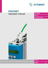
PROFIBUS<br />
Operation manual<br />
Fundamentals<br />
<strong>Co</strong>nfiguration<br />
Parameters<br />
V 5.6-E or later<br />
04/2012 en
Table of contents<br />
Operation manual<br />
Table of contents<br />
1 Introduction . . . . . . . . . . . . . . . . . . . . . . . . . . . . . 4<br />
1.1 Purpose of the manual . . . . . . . . . . . . . . . . . . . . . . . . . . . . . . 4<br />
1.2 Readers . . . . . . . . . . . . . . . . . . . . . . . . . . . . . . . . . . . . . . . . . 4<br />
1.3 Other manuals . . . . . . . . . . . . . . . . . . . . . . . . . . . . . . . . . . . . 4<br />
1.4 Further support . . . . . . . . . . . . . . . . . . . . . . . . . . . . . . . . . . . . 5<br />
2 Notes on Safety. . . . . . . . . . . . . . . . . . . . . . . . . . 6<br />
2.1 <strong>Co</strong>mponent part of the product . . . . . . . . . . . . . . . . . . . . . . . . 6<br />
2.2 Operation in accordance with its intended use . . . . . . . . . . . . 6<br />
2.3 Qualified personnel . . . . . . . . . . . . . . . . . . . . . . . . . . . . . . . . . 7<br />
2.4 Transportation and storage . . . . . . . . . . . . . . . . . . . . . . . . . . . 7<br />
2.5 Installation and connection . . . . . . . . . . . . . . . . . . . . . . . . . . . 8<br />
2.6 Service . . . . . . . . . . . . . . . . . . . . . . . . . . . . . . . . . . . . . . . . . . 8<br />
2.7 Disposal . . . . . . . . . . . . . . . . . . . . . . . . . . . . . . . . . . . . . . . . . 8<br />
2.8 Presentation of notes on safety. . . . . . . . . . . . . . . . . . . . . . . . 9<br />
3 Mounting . . . . . . . . . . . . . . . . . . . . . . . . . . . . . . . 10<br />
3.1 Install in MDS 5000 or SDS 5000 . . . . . . . . . . . . . . . . . . . . . . 10<br />
3.2 Installation in the FDS 5000 . . . . . . . . . . . . . . . . . . . . . . . . . . 13<br />
4 Electrical installation . . . . . . . . . . . . . . . . . . . . . 16<br />
4.1 Setup. . . . . . . . . . . . . . . . . . . . . . . . . . . . . . . . . . . . . . . . . . . . 16<br />
4.2 Cable specifications . . . . . . . . . . . . . . . . . . . . . . . . . . . . . . . . 17<br />
4.3 <strong>Co</strong>nnection of the bus cables to the inverter. . . . . . . . . . . . . . 18<br />
5 Fundamentals of PROFIBUS . . . . . . . . . . . . . . . 19<br />
5.1 PROFIdrive profil version 3. . . . . . . . . . . . . . . . . . . . . . . . . . . 19<br />
5.2 <strong>Co</strong>mparison of the PROFIBUS generations . . . . . . . . . . . . . . 20<br />
5.3 Data transmission via PROFIBUS DP . . . . . . . . . . . . . . . . . . 21<br />
5.3.1 Possible communication . . . . . . . . . . . . . . . . . . . . . 21<br />
5.3.2 User data communication. . . . . . . . . . . . . . . . . . . . . 22<br />
6 Bus diagnosis/LEDs . . . . . . . . . . . . . . . . . . . . . . 23<br />
WE KEEP THINGS MOVING<br />
ID 441687.03<br />
2
Table of contents<br />
Operation manual<br />
7 <strong>Co</strong>nfiguration of the bus system. . . . . . . . . . . . 25<br />
7.1 GSD file. . . . . . . . . . . . . . . . . . . . . . . . . . . . . . . . . . . . . . . . . . 25<br />
7.2 Procedure for SIEMENS SIMATIC S7 and STEP 7 . . . . . . . . 26<br />
7.2.1 The HW-config . . . . . . . . . . . . . . . . . . . . . . . . . . . . . 26<br />
7.2.2 SFC Calls for data consistency . . . . . . . . . . . . . . . . 27<br />
8 Prozess data transmission PZD . . . . . . . . . . . . 28<br />
8.1 Parameter process data object (PPO) . . . . . . . . . . . . . . . . . . 28<br />
8.2 The mapping . . . . . . . . . . . . . . . . . . . . . . . . . . . . . . . . . . . . . . 29<br />
8.2.1 Example PPO4 with 12-Byte PZD area . . . . . . . . . . 30<br />
9 <strong>Co</strong>ntrol with control and status bits . . . . . . . . . 31<br />
10 Switchable scaling . . . . . . . . . . . . . . . . . . . . . . . 32<br />
11 Parameter Overview . . . . . . . . . . . . . . . . . . . . . . 33<br />
11.1 PROFIDRIVE parameter. . . . . . . . . . . . . . . . . . . . . . . . . . . . . 33<br />
11.2 PROFIBUS parameter/mapping/PKW1 . . . . . . . . . . . . . . . . . 34<br />
11.3 List of the primary communication parameters . . . . . . . . . . . . 35<br />
11.4 List of quick location of parameters. . . . . . . . . . . . . . . . . . . . . 40<br />
12 Appendix A . . . . . . . . . . . . . . . . . . . . . . . . . . . . . 41<br />
12.1 General characteristics . . . . . . . . . . . . . . . . . . . . . . . . . . . . . . 41<br />
12.2 Parameter jobs and responses . . . . . . . . . . . . . . . . . . . . . . . . 41<br />
12.3 DPV1 telegram sequences . . . . . . . . . . . . . . . . . . . . . . . . . . . 46<br />
12.3.1 DPV1 telegram frame. . . . . . . . . . . . . . . . . . . . . . . . 47<br />
13 Appendix B PKW0 telegram. . . . . . . . . . . . . . . . 50<br />
13.1 PKW0 mechanism . . . . . . . . . . . . . . . . . . . . . . . . . . . . . . . . . 50<br />
13.2 Further regulations for order/ans<strong>we</strong>r processing . . . . . . . . . . 54<br />
13.3 Time sequence of a PKW0 service . . . . . . . . . . . . . . . . . . . . . 54<br />
WE KEEP THINGS MOVING<br />
ID 441687.03<br />
3
Introduction<br />
Operation manual<br />
1<br />
1 Introduction<br />
1.1 Purpose of the manual<br />
This manual gives you information on the connection of the 5 th generation of<br />
STÖBER inverters to the PROFIBUS fieldbus system. The structure of<br />
PROFIBUS and the principal procedures are also discussed.<br />
Goals of the manual:<br />
• Provide you with a basic knowledge of PROFIBUS communication.<br />
• Offer you support when you design an application and configure<br />
communication.<br />
1.2 Readers<br />
Users who are familiar with the control of drive systems and have a knowledge of<br />
commissioning inverter systems are the target group of this manual.<br />
1.3 Other manuals<br />
The documentation of the MDS 5000 includes the following manuals:<br />
Manual <strong>Co</strong>ntents ID Latest version a)<br />
<strong>Co</strong>mmissioning Instructions Reinstallation, replacement, function test 442297 V 5.6-E<br />
Projecting manual Installation and connection 442273 V 5.6-E<br />
Operating manual Set up the inverter 442285 V 5.6-E<br />
a) At the time of publication. You can find all versions at www.stoeber.de > Products > Doc Center.<br />
The documentation of the FDS 5000 includes the following manuals:<br />
Manual <strong>Co</strong>ntents ID Latest version a)<br />
<strong>Co</strong>mmissioning Instructions Reinstallation, replacement, function test 442293 V 5.6-E<br />
Projecting manual Installation and connection 442269 V 5.6-E<br />
Operating manual Set up the inverter 442281 V 5.6-E<br />
a) At the time of publication. You can find all versions at www.stoeber.de > Products > Doc Center.<br />
The documentation of the SDS 5000 includes the following manuals:<br />
Manual <strong>Co</strong>ntents ID Latest version a)<br />
<strong>Co</strong>mmissioning Instructions Reinstallation, replacement, function test 442301 V 5.6-E<br />
Projecting manual Installation and connection 442277 V 5.6-E<br />
Operating manual Set up the inverter 442289 V 5.6-E<br />
a) At the time of publication. You can find all versions at www.stoeber.de > Products > Doc Center.<br />
WE KEEP THINGS MOVING<br />
ID 441687.03<br />
4
Introduction<br />
Operation manual<br />
1<br />
You can find information on the POSITool software in the following manuals:<br />
Manual <strong>Co</strong>ntents ID Latest version a)<br />
POSITool operating manual Information on the 442233 V 5.6-E<br />
basic functions of<br />
POSITool<br />
Programming manual<br />
Information on 441693 V 5.6-E<br />
programming with<br />
POSITool<br />
a) At the time of publication. You can find all versions at www.stoeber.de > Products > Doc Center.<br />
Note that the programming functionality of POSITool can only be used after<br />
training by STÖBER <strong>ANTRIEBSTECHNIK</strong>. You can find information on training at<br />
www. stoeber.de<br />
1.4 Further support<br />
For questions which have not been ans<strong>we</strong>red by this manual, do not hesitate to<br />
contact us at:<br />
• telephone: +49 (0) 7231 582-1187 or<br />
• E-Mail: applications@stoeber.de<br />
To make it easier for you to start using our software, <strong>we</strong> offer associated seminars.<br />
Please see our range of seminars at www.stoeber.de or contact our training<br />
center at the e-mail address training@stoeber.de.<br />
WE KEEP THINGS MOVING<br />
ID 441687.03<br />
5
Notes on Safety<br />
Operation manual<br />
2<br />
2 Notes on Safety<br />
The devices may cause risks. For these reasons, comply with the following:<br />
• The safety notes listed in the following sections and points<br />
• The technical rules and regulations.<br />
In addition, always read the appropriate documentation. STÖBER<br />
<strong>ANTRIEBSTECHNIK</strong> <strong>GmbH</strong> + <strong>Co</strong>. KG accepts no liability for damages caused by<br />
non-adherence to the instructions or applicable regulations. Subject to technical<br />
changes to improve the devices without prior notice. This documentation is purely<br />
a product description. It does not represent promised properties in the sense of<br />
warranty law.<br />
2.1 <strong>Co</strong>mponent part of the product<br />
The technical documentation is a component part of a product.<br />
• Since the technical documentation contains important information, always<br />
<strong>keep</strong> it handy in the vicinity of the device until the machine is disposed of.<br />
• If the product is sold, disposed of, or rented out, always include the technical<br />
documentation with the product.<br />
2.2 Operation in accordance with its intended use<br />
The DP5000 accessory is only intended for establishing communication bet<strong>we</strong>en<br />
devices from the 5th generation of STÖBER inverters and a PROFIBUS network.<br />
Improper use includes integration in other communication networks.<br />
WE KEEP THINGS MOVING<br />
ID 441687.03<br />
6
Notes on Safety<br />
Operation manual<br />
2<br />
2.3 Qualified personnel<br />
Since the devices may harbor residual risks, all configuration, transportation,<br />
installation and commissioning tasks including operation and disposal may only<br />
be performed by trained personnel who are aware of the possible risks.<br />
Personnel must have the qualifications required for the job. The following table<br />
lists examples of occupational qualifications for the jobs:<br />
Activity<br />
Possible occupational qualifications<br />
Transportation and storage Worker skilled in storage logistics or comparable<br />
training<br />
<strong>Co</strong>nfiguration<br />
- Graduate engineer (electro-technology or<br />
electrical po<strong>we</strong>r technology)<br />
- Technician (m/f) (electro-technology)<br />
Installation and connection Electronics technician (m/f)<br />
<strong>Co</strong>mmissioning<br />
- Technician (m/f) (electro-technology)<br />
(of a standard application) - Master electro technician (m/f)<br />
Programming<br />
Graduate engineer (electro-technology or<br />
electrical po<strong>we</strong>r technology)<br />
Operation<br />
- Technician (m/f) (electro-technology)<br />
- Master electro technician (m/f)<br />
Disposal<br />
Electronics technician (m/f)<br />
Tab. 2-1: examples of occupational qualifications<br />
In addition, the valid regulations, the legal requirements, the reference books, this<br />
technical documentation and, in particular, the safety information contained<br />
therein must be carefully<br />
• read<br />
• understood and<br />
• complied with<br />
2.4 Transportation and storage<br />
Inspect the delivery for any transport damage immediately after you receive it.<br />
Notify any damage to the transport company immediately. Do not operate the<br />
product if damaged. Store the device in a dry and dust-free room if you do not<br />
install it immediately<br />
WE KEEP THINGS MOVING<br />
ID 441687.03<br />
7
Notes on Safety<br />
Operation manual<br />
2<br />
2.5 Installation and connection<br />
The accessory installation instructions allow the following actions during the<br />
installation of accessories:<br />
• The housing in the upper slot can be opened.<br />
Opening the housing in another place or for other purposes is not permitted.<br />
Installation and connection work are only permitted after the device has been<br />
isolated from the po<strong>we</strong>r!<br />
Apply the 5 safety rules in the order stated before performing any work on the<br />
machine:<br />
1. Enable. Also enable the auxiliary circuits.<br />
2. Secure against restart.<br />
3. Check that voltage is not present.<br />
4. Earth and short circuit.<br />
5. <strong>Co</strong>ver adjacent live parts.<br />
Information<br />
Note that the discharge time of the DC link capacitors is 5 minutes. You<br />
can only determine the absence of voltage after this time period.<br />
Afterwards you can carry out the work.<br />
2.6 Service<br />
Repairs must only be performed by STÖBER <strong>ANTRIEBSTECHNIK</strong> <strong>GmbH</strong> + <strong>Co</strong>.<br />
KG. Send faulty devices with a fault description to:<br />
STÖBER <strong>ANTRIEBSTECHNIK</strong> <strong>GmbH</strong> + <strong>Co</strong>. KG<br />
Abteilung VS-EL<br />
Kieselbronner Str.12<br />
75177 Pforzheim, Germany<br />
GERMANY<br />
2.7 Disposal<br />
Please comply with the latest national and regional regulations! Dispose of the<br />
individual parts separately depending on their nature and currently valid<br />
regulations such as, for example:<br />
• Electronic scrap (PCBs)<br />
• Plastic<br />
• Sheet metal<br />
• <strong>Co</strong>pper<br />
• Aluminum<br />
WE KEEP THINGS MOVING<br />
ID 441687.03<br />
8
Notes on Safety<br />
Operation manual<br />
2<br />
2.8 Presentation of notes on safety<br />
NOTICE<br />
Notice<br />
means that property damage may occur<br />
if the stated precautionary measures are not taken.<br />
CAUTION!<br />
Caution<br />
with warning triangle means that minor injury may occur<br />
if the stated precautionary measures are not taken.<br />
WARNING!<br />
Warning<br />
means that there may be a serious danger of death<br />
if the stated precautionary measures are not taken.<br />
DANGER!<br />
Danger<br />
means that serious danger of death exists<br />
if the stated precautionary measures are not taken.<br />
Information<br />
indicates important information about the product or a highlighted<br />
portion of the documentation which requires special attention.<br />
WE KEEP THINGS MOVING<br />
ID 441687.03<br />
9
Mounting<br />
Operation manual<br />
3<br />
3 Mounting<br />
The DP 5000 fieldbus module (PROFIBUS DP-V1) must first be installed before<br />
the inverter of the 5 th generation of STÖBER inverters can be integrated in a<br />
PROFIBUS system. The accessories are installed above the inverter display.<br />
We recommend ordering the option card with mounting and the inverter. If this is<br />
done, STÖBER <strong>ANTRIEBSTECHNIK</strong> will mount the DP 5000 before delivery.<br />
3.1 Install in MDS 5000 or SDS 5000<br />
WARNING!<br />
Danger of injury/death and property damage due to electric shock!<br />
Before installing accessories, turn off all voltage supplies! Then wait 5<br />
minutes for the DC link capacitors to discharge. Never begin with accessory<br />
installation until after this!<br />
CAUTION!<br />
Danger of property damage due to electrostatic discharge, among others!<br />
Provide suitable protective measures while handling open PCBs (e.g., ESD<br />
clothing, environment free of dirt and grease).<br />
Do not touch the gold contact surfaces.<br />
You will need the following tools to install the DP 5000:<br />
• TX10 Torx screwdriver<br />
• Pliers<br />
• Hexagon socket wrench, 4.5 mm<br />
Installing the DP 5000<br />
1 Unscrew the mounting screws and remove the cover plate:<br />
WE KEEP THINGS MOVING<br />
ID 441687.03<br />
10
Mounting<br />
Operation manual<br />
3<br />
2 Remove the punched out metal section with the pliers:<br />
3 Remove the screws from the option PCB:<br />
4 Stick the sub D plug connector of the PCB through the plate from below:<br />
5 Secure the PCB to the plate with the screw in step 3:<br />
WE KEEP THINGS MOVING<br />
ID 441687.03<br />
11
Mounting<br />
Operation manual<br />
3<br />
6 Insert the option PCB in the inverter so that the gold contacts slide into the<br />
black terminal block:<br />
7 Secure the plate to the inverter with the mounting screws:<br />
<br />
You have installed the accessory.<br />
WE KEEP THINGS MOVING<br />
ID 441687.03<br />
12
Mounting<br />
Operation manual<br />
3<br />
3.2 Installation in the FDS 5000<br />
WARNING!<br />
Danger of injury/death and property damage due to electric shock!<br />
Before installing accessories, turn off all voltage supplies! Then wait 5<br />
minutes for the DC link capacitors to discharge. Never begin with accessory<br />
installation until after this!<br />
CAUTION!<br />
Danger of property damage due to electrostatic discharge, among others!<br />
Provide suitable protective measures while handling open PCBs (e.g., ESD<br />
clothing, environment free of dirt and grease).<br />
Do not touch the gold contact surfaces.<br />
You will need the following tools to install the DP 5000:<br />
• TX10 Torx screwdriver<br />
• Pliers<br />
• Hexagon socket wrench, 4.5 mm<br />
Installing the DP 5000 in an FDS 5000<br />
1 Unscrew the mounting screws and remove the cover plate:<br />
2 Remove the punched out metal section with the pliers:<br />
WE KEEP THINGS MOVING<br />
ID 441687.03<br />
13
Mounting<br />
Operation manual<br />
3<br />
3 Remove the screws from the option PCB:<br />
4 Stick the sub D plug connector of the PCB through the plate from below:<br />
5 Secure the PCB to the plate with the screws from step 3:<br />
6 Stick the option PCB in the inverter so that the gold contacts slide into the<br />
black terminal block:<br />
WE KEEP THINGS MOVING<br />
ID 441687.03<br />
14
Mounting<br />
Operation manual<br />
3<br />
7 Secure the plate to the inverter with the mounting screws:<br />
<br />
You have installed the accessory.<br />
WE KEEP THINGS MOVING<br />
ID 441687.03<br />
15
Electrical installation<br />
Operation manual<br />
4<br />
4 Electrical installation<br />
4.1 Setup<br />
PROFIBUS DP consists of at least one bus segment. One segment consists of at<br />
least two but not more than 32 stations. They are all physically connected with a<br />
bus cable. One of the stations is the master. The master is the active station on<br />
PROFIBUS. It can send or request data to/from other stations. The slaves are the<br />
passive stations on PROFIBUS. They can only exchange data with the master<br />
when the master requests this.<br />
Terminating resistors must be placed at the beginning and the end of the bus.<br />
Master no. 1<br />
Slave no. 2<br />
Slave no. 3<br />
Slave no.<br />
Station (master or slave)<br />
Station with circuited<br />
terminating resistor<br />
Fig. 4-1: Setup of a bus segment<br />
If more than 32 stations are to operate on a bus or the maximum line length of a<br />
bus segment is exceeded, several bus segments must be coupled via RS 485<br />
repeaters. The maximum number of masters and slaves within one bus segment<br />
must be decreased by one for every repeater used. The maximum number of<br />
masters and slaves over the entire bus system is 126. The maximum line length<br />
depends on the baud rate being used. The table below gives you the maximum<br />
permissible lengths for one segment and for all segments.<br />
We strongly recommend NOT using stub lines in the setup. This is only permitted<br />
during commissioning. This bus system is usually set up with shielded, two-wire<br />
lines (RS 485). It can also be set up for special applications via fiber-optic<br />
conductors. STÖBER Antriebstechnik offers the coupling to the two-wire line.<br />
This permits a maximum distance of 10,000 m. When suitable measures are<br />
taken on the master side, slaves can be coupled or decoupled during operation<br />
without having to interrupt data communication on the bus.<br />
WE KEEP THINGS MOVING<br />
ID 441687.03<br />
16
Electrical installation<br />
Operation manual<br />
4<br />
Baud rate one segment all segments<br />
9.6 to 187.5 kBaud 1000 m 10000 m<br />
500 kBaud 400 m 4000 m<br />
1.5 Mbaud 200 m 2000 m<br />
3 to 12 Mbaud 100 m 1000 m<br />
These distances only apply with suitable bus cable!<br />
Segment 1<br />
R<br />
Repeater<br />
Segment 2<br />
Repeater<br />
R<br />
Segment 3<br />
Fig. 4-2: Setup with more than 32 stations<br />
4.2 Cable specifications<br />
To ensure interference-free use of the above baud rates and distances, STÖBER<br />
<strong>ANTRIEBSTECHNIK</strong> recommends using cable type A with the folloeing<br />
specification described in PROFIBUS literature:<br />
• Wave resistance: 135 to 165 Ω, at a measuring frequency of 3 to 20 MHz.<br />
• Cable capacity: < 30 pF per meter<br />
• <strong>Co</strong>re cross section: > 0,34 mm²<br />
• Loop resistance: < 110 Ohm per km<br />
• Signal attenuation: Max. of 9 dB over the entire length of the line segment.<br />
• Shielding: Braided copper shield or braided shield and foil shield.<br />
Use of other types of cables is not recommended since then only slo<strong>we</strong>r baud<br />
rates and reduced distances may be possible.<br />
WE KEEP THINGS MOVING<br />
ID 441687.03<br />
17
Electrical installation<br />
Operation manual<br />
4<br />
4.3 <strong>Co</strong>nnection of the bus cables to the inverter<br />
To connect PROFIBUS DP, the DP5000 option module is equipped with a 9-pin,<br />
sub D socket plug connector with the pin allocation specified in the PROFIBUS<br />
standard (see below).<br />
To connect the bus cable(s), <strong>we</strong> recommend the use of suitable bus connection<br />
plugs which are offered by various manufacturers especially for PROFIBUS DP.<br />
The incoming and the outgoing bus cable can be inserted and scre<strong>we</strong>d down in<br />
these plug connectors. There is no outgoing bus cable for the last station. In this<br />
case the sliding switch on the plug is set to "on" to switch on the bus terminating<br />
resistors.<br />
Information<br />
To ensure that bus termination functions correctly, the po<strong>we</strong>r supply<br />
may not be allo<strong>we</strong>d to fail on the stations with circuited terminating<br />
resistors! To bypass the risk of a complete bus failure when the last<br />
station malfunctions, active bus terminating components can be used.<br />
The inverters in the device series MDS 5000 and SDS 5000 with a<br />
separate 24-V control part po<strong>we</strong>r supply represent such components.<br />
In the device series FDS 5000, inverters with the identifier "/L" have a<br />
separate 24-V control part po<strong>we</strong>r supply.<br />
PIN a)<br />
Designation Function<br />
1 nc Not connected<br />
2 nc Not connected<br />
3 B RxD/TxD-P (send/receive data - plus)<br />
4 RTS Direction control for repeater (plus)<br />
5 GND Ground to +5 V<br />
6 +5V Po<strong>we</strong>r for the terminating resistors<br />
7 nc Not connected<br />
8 A RxD/TxD-N (send/receive data - minus)<br />
9 nc Not connected<br />
a) View of sub D<br />
WE KEEP THINGS MOVING<br />
ID 441687.03<br />
18
Fundamentals of PROFIBUS<br />
Operation manual<br />
5<br />
5 Fundamentals of PROFIBUS<br />
PROFIBUS is an open fieldbus standard for a wide variety of applications in<br />
manufacturing and process automation. The independence from manufacturers<br />
and the openness are ensured by international standard IEC 61158. For years<br />
now PROFIBUS has been one of the primary fieldbus systems on the<br />
international market.<br />
PROFIBUS DP is a fast and cost-optimized communication system for use at the<br />
field level in which a controller (PROFIBUS master) with several slaves (drives,<br />
IOs, and so on) performs cyclic data communication.<br />
5.1 PROFIdrive profil version 3<br />
There are three types: PROFIBUS FMS, PROFIBUS DP and PROFIBUS<br />
PA.PROFIBUS DP offers high-speed cyclic communication for small amounts of<br />
data.<br />
The PROFIBUS profile drive technology, called PROFIDrive, version 3, is a<br />
compatible continuation of the proven PROFIBUS profile for variable-speed<br />
drives, PROFIDrive, version 2. Today PROFIBUS communication is the standard<br />
for drive technology.<br />
In addition to the PROFIBUS standard, the PROFIDrive profile specifies uniform<br />
device reactions and access procedures for the drive data. One of the new<br />
functions of version 3 is the parameter channel which uses the DP-V1 services of<br />
the acyclic communication.<br />
STÖBER <strong>ANTRIEBSTECHNIK</strong> offers all inverters of the 5 th generation of<br />
STÖBER inverters the capacity to connect to PROFIBUS DP (DP = Decentral<br />
Periphery) via the PROFIDrive profile. This turns these devices into intelligent DP<br />
slaves which can be operated by a PROFIBUS master (controller, PLS, PC).<br />
Bus operation is possible up to a maximum speed of 12 Mbaud. Two LEDs<br />
indicate the function of the option board, the status of the data transmission and<br />
any malfunction (see chapter 6).<br />
When a PROFIBUS system is commissioned, the manuals/commissioning<br />
instructions of all involved components (DP master/controller, additional slaves,<br />
etc.) must be adhered to. For further information on PROFIBUS or PROFIDrive<br />
profile, go to www.profibus.com at the PROFIBUS User Organization.<br />
WE KEEP THINGS MOVING<br />
ID 441687.03<br />
19
Fundamentals of PROFIBUS<br />
Operation manual<br />
5<br />
5.2 <strong>Co</strong>mparison of the PROFIBUS generations<br />
This chapter summarizes the system characteristics applicable to drive<br />
technology and the system differences:<br />
Simultaneous operation of different inverter generations on one controller is<br />
possible and easy (see figure). Only when the new acyclic services are used are<br />
an inverter of the 5 th generation of STÖBER inverters and an appropriate master<br />
required. The use of these services does not interfere with the operation of the<br />
other stations. When an older controller is used which does not support acyclic<br />
services, operation with cyclic data (PZD and PKW) can be used.<br />
MDS<br />
5000<br />
FDS<br />
5000<br />
SDS<br />
5000<br />
FDS<br />
4000<br />
FAS<br />
4000<br />
Fig. 5-1: Schematic setup with different types of STÖBER inverters<br />
PROFIBUS<br />
DP-V0<br />
DP-V1<br />
Standard<br />
Properties<br />
Cyclic data<br />
communication (PZD<br />
+ PKW)<br />
Zyklischer Datenaustausch<br />
identisch<br />
wie DP-V0<br />
New Features<br />
Meaning for FDS<br />
5000 / MDS 5000<br />
— <strong>Co</strong>mpatible with FDS<br />
4000, ...<br />
Acyclic services +<br />
alarm handling<br />
New parameter<br />
channel, available as<br />
per PROFIDrive V3<br />
WE KEEP THINGS MOVING<br />
ID 441687.03<br />
20
Fundamentals of PROFIBUS<br />
Operation manual<br />
5<br />
5.3 Data transmission via PROFIBUS DP<br />
5.3.1 Possible communication<br />
Devices of the 5 th generation of STÖBER inverters support cyclic and acyclic<br />
services with the DP-V1 option. This provides a wide variety of possible ways to<br />
communicate:<br />
C2 - Master<br />
C2 - Master<br />
C1 - Master<br />
HMI<br />
1<br />
3<br />
2<br />
4<br />
Fig. 5-2: Different communication options<br />
1: Cyclic communication<br />
2 - 4: Acyclic communication<br />
Cyclic communication (1) is the simple exchange of user data via the data<br />
exchange telegram. Time critical process data (PZD) are exchanged bet<strong>we</strong>en a<br />
class-1 master (C1) and the drive controller with cyclic communication. Such data<br />
include, for example, reference and actual values, and control and status<br />
information. A routine for parameter communication (of the familiar PKW channel<br />
as with the FDS 4000) can be implemented within the cyclic communication.<br />
There is always exactly one C1 master in each PROFIBUS setup. This master<br />
reads the GSD file, configures the drives, starts PROFIBUS and runs the cyclic<br />
communication. The C1 master is usually the controller (arrow 1).<br />
The acyclic services (2-4) are available in DP-V1 for the transmission of new<br />
parameter jobs for controlling and monitoring the drives, parallel to true cyclic<br />
communication.<br />
WE KEEP THINGS MOVING<br />
ID 441687.03<br />
21
Fundamentals of PROFIBUS<br />
Operation manual<br />
5<br />
In contrast to cyclic communication, acyclic communication data are only<br />
exchanged when necessary. Acyclic communication is performed either via an<br />
appropriate routine within cyclic communication (for PKW routine, see<br />
PROFIDrive profile version 2) or via the DP-V1 routines READ and WRITE. This<br />
permits the connection of commissioning tools as class-2 master (C2) to<br />
PROFIBUS.<br />
Several acyclic channels are available at the same time. The C1 master (the<br />
controller) maintains a continuously open connection to the inverter (MSAC1)<br />
which can be used as necessary by the controller program (arrow 2). In addition,<br />
the inverter provides the capacity for two connections (MSAC2) which can be<br />
established and used as necessary by C2 masters (e.g., an operator panel or a<br />
service PC).<br />
Time wise on PROFIBUS, the cyclic data always have the highest priority. During<br />
each data exchange cycle, the master inserts an acyclic telegram when<br />
necessary. This does not noticeably affect the speed of PROFIBUS.<br />
5.3.2 User data communication<br />
The process data channel is used for high-speed transmission of data which are<br />
used for controlling and monitoring the running process and which require a<br />
particularly short transmission time. When the bus system is configured, the<br />
selection of the PPO type specifies whether the cyclic parameter channel is to be<br />
used and how many bytes the process data channel will have.<br />
All parameters can be read and changed with the parameter channels. First, the<br />
PKW1 routine (which uses the acyclic services of PROFIBUS) specified by<br />
PROFIDrive version 3 is available and, second, the old PKW0 routine (which is<br />
embedded in the cyclic data) defined by PROFIDrive version 2 is offered.<br />
Because of the comprehensive capabilities and the access to all inverter<br />
parameters without exception, the new PKW1 routine should be used if possible:<br />
Transmission Channel Inverter with Option DP-V1 5000<br />
Process data reference values<br />
from the bus to the processing on<br />
the device.<br />
<strong>Co</strong>mplete processing of a PKW0<br />
service.<br />
PKW1 via acyclic services.<br />
Depends on the configuration and setting of<br />
the parameter A150 cycle time.<br />
Approx. 16 to 64 ms<br />
Depends on the configuration!<br />
Approx. 16 to 64 ms<br />
Depends on the configuration!<br />
WE KEEP THINGS MOVING<br />
ID 441687.03<br />
22
Bus diagnosis/LEDs<br />
Operation manual<br />
6<br />
6 Bus diagnosis/LEDs<br />
The DP 5000 option module is equipped with a green and a red LED. The LEDs<br />
indicate communication-specific states. This permits the PROFIBUS status to be<br />
diagnosed on the device.<br />
RED<br />
GREEN<br />
Fig. 6-1: View on LED<br />
Red LED Green Bedeutung/Maßnahme<br />
LED<br />
Off Off No connection bet<strong>we</strong>en the inverter and the PROFIBUS<br />
board (board was not recognized or has failed. See<br />
parameter E54 option module 1).<br />
Flashing Off PROFIBUS master stopped bus for more than 25 s (PLC in<br />
stop) or has failed or bus cable no longer connected (see<br />
parameter A84 PROFI-Baud).<br />
Off Flashing Device is ready and is waiting for the PROFIBUS master to<br />
start or:When this state does not change although the<br />
PROFIBUS master has already attempted to establish a<br />
connection, this means that the applicable function blocks<br />
for PROFIBUS have not been downloaded to the inverter.<br />
Off On Device was configured by PROFIBUS master and data<br />
communication was started.<br />
Flashing Flashing PROFIBUS master stopped the bus just a few seconds ago<br />
(< 25 s) (PLC in stop) or has failed or bus cable is no longer<br />
connected (see parameter A84 PROFI-Baud).<br />
WE KEEP THINGS MOVING<br />
ID 441687.03<br />
23
Bus diagnosis/LEDs<br />
Operation manual<br />
6<br />
The following diagnostic capabilities are available:<br />
• The two LEDs on the option board DP 5000<br />
• Parameter A84 PROFIBUS Baudrate<br />
• Parameter A86 PROFIBUS configuration<br />
• Parameter A85 PROFIBUS diagnosis (indication of internal inverter<br />
diagnostic information via the PROFIBUS interface).<br />
Parameter A85 is composed of the following bits:<br />
Bit Name Meaning for Bit = 1<br />
0 Shutdown-Fail Problems during shutting down the PROFIBUS driver<br />
software<br />
1 Data-Exchange PROFIBUS is in the state of cyclic data communication<br />
with this station.<br />
2 Wait for Param Station is waiting to be parameterized by the<br />
PROFIBUS master.<br />
3 Bus-Failure Error on PROFIBUS<br />
4 Acyc. Initiate 1 An acyclic connection has been established.<br />
5 Acyc. Initiate 2 A second acyclic connection has been established.<br />
6 MDS configured Station has been configured by the PROFIBUS master.<br />
7 Driver-Error Error in the PROFIBUS driver software.<br />
8 Application ready Inverter firmware is ready for a connection to<br />
PROFIBUS.<br />
9 LED red on The red LED of the DP 5000 is now on.<br />
10 LED green on The green LED of the DP 5000 is now on.<br />
WE KEEP THINGS MOVING<br />
ID 441687.03<br />
24
<strong>Co</strong>nfiguration of the bus system<br />
Operation manual<br />
7<br />
7 <strong>Co</strong>nfiguration of the bus system<br />
7.1 GSD file<br />
Wiring all bus stations together is not sufficient to commission PROFIBUS DP.<br />
The following additional measures are required:<br />
• Different bus addresses must be set on the master and on all slaves.<br />
• With older slaves which are unable to find the baud rate automatically, the<br />
same baud rate must be set as on the master (the devices of the 5 th<br />
generation of STÖBER inverters are able to find the baud rate automatically).<br />
• The master must be informed as to how many slaves are connected together<br />
with their characteristics and bus addresses.<br />
The baud rate must be set on the master under consideration of the segment<br />
lengths and the total distance of the bus.<br />
This work is performed on the master side using configuration software. This<br />
software must read the device master data files (GSD files) from all stations. The<br />
GSD files are like electronic data sheets which contain the information on the<br />
PROFIBUS characteristics such as supported baud rates, supported modules,<br />
and so on. They are provided by the manufacturer for each PROFIBUS device.<br />
The GSD file for the devices of the 5th generation of STÖBER inverters has the<br />
designation STOE5005.GSD. The file can be downloaded from the Internet under<br />
www.stoeber.de.<br />
Information<br />
The change in the PROFIBUS address of a slave is not accepted until<br />
the next device startup of the bus master. This was standardized to<br />
prevent the occurrence of dangerous system states due to double/nonaddressed<br />
stations. Before switch-off, it is imperative that the drive data<br />
be stored on the inverter safe from a po<strong>we</strong>r failure with A00 save values<br />
= 1. After action A00 is concluded successfully, the device can be<br />
turned off and on. After this the new PROFIBUS address is active.<br />
WE KEEP THINGS MOVING<br />
ID 441687.03<br />
25
<strong>Co</strong>nfiguration of the bus system<br />
Operation manual<br />
7<br />
7.2 Procedure for SIEMENS SIMATIC S7 and STEP 7<br />
Different configuration software is used for different PROFIBUS masters. How<br />
this works with the SIMATIC Manager for the SIMATIC S7 in version 5.1 will be<br />
explained with an example. At least version 5.1 SP4 of STEP 7 is required for use<br />
of DPV1 with STEP 7. The SIMATIC S7 CPUs must also support DPV1. For<br />
whether the particular CPU supports DPV1, see the CPU characteristics under<br />
the hardware manager.<br />
7.2.1 The HW-config<br />
To link in the GSD file in the STEP 7, open the menu "Extras" "Neue GSD Datei<br />
einbinden." Then display the GSD in the device catalog under "Extras" "Katalog<br />
Aktualisieren." This must done only once. After this, the inverter appears at the<br />
position as shown on the screen (Fig. 7-1) in the hardware catalog. HW-<strong>Co</strong>nfig in<br />
STEP 7 may look like this.<br />
Fig. 7-1: HW-<strong>Co</strong>nfig<br />
It is not necessary to reserve a separate memory area for the acyclic services<br />
(DPV1). This means that no PPO type must be selected which supports PKW.<br />
Every PPO type has this capability with the DPV1 protocol.<br />
WE KEEP THINGS MOVING<br />
ID 441687.03<br />
26
<strong>Co</strong>nfiguration of the bus system<br />
Operation manual<br />
7<br />
7.2.2 SFC Calls for data consistency<br />
To ensure data consistency on the bus, SIEMENS requires that SFCs 14 and 15<br />
be used for data lengths longer than a double word. Direct accesses to the IO<br />
area via L PAW or L PEW are then NOT permitted. The SFCs must be called once<br />
per slave.<br />
Fig. 7-2: SIEMENS SFC's 14/15<br />
WE KEEP THINGS MOVING<br />
ID 441687.03<br />
27
Prozess data transmission PZD<br />
Operation manual<br />
8<br />
8 Prozess data transmission PZD<br />
8.1 Parameter process data object (PPO)<br />
The 5 th generation of STÖBER inverters offer various telegram types in the GSD<br />
file for cyclic data transmission. The master selects one of the possibilities to<br />
configure the inverter and then start the bus. These possibilities are called<br />
parameter process data object (PPO types) and always contain the process data<br />
channel (PZD) and sometimes also a parameter channel (PKW0). The Devices<br />
of the 5 th generation of STÖBER inverters provide five different PPO types to<br />
choose from for the establishment of this user data structure.<br />
To be able to use the functionality of process data transmission, the applicable<br />
blocks must be activated by the PC software POSITool. This is done by selecting<br />
a suitable application in user-prompted commissioning and then downloading it to<br />
the inverter. PPO types 3 and 4 do not need a separate memory area for the<br />
PKW1 service of the DP-V1 protocol.<br />
PKW<br />
PZD<br />
PKE IND<br />
PWE<br />
PZD1, 2, 3, 4, 5 6<br />
Bytes 0 1… … 19<br />
PPO1<br />
PPO2<br />
PPO3<br />
PPO4<br />
PPO5<br />
PKW : Parameter ID value<br />
PZD : Process data<br />
PKE : Parameter ID<br />
IND : Subindex in byte 2, Byte 3 is reserved<br />
PWE : Parameter value<br />
Fig. 8-1: PPO-Typen<br />
WE KEEP THINGS MOVING<br />
ID 441687.03<br />
28
Prozess data transmission PZD<br />
Operation manual<br />
8<br />
8.2 The mapping<br />
Mapping manages the allocation of incoming data from the bus to the inverter<br />
parameters and vice versa.<br />
Information<br />
A new mapping does not become active until the following has taken<br />
place:<br />
1. Back up the changed mapping with the A00 function Save values.<br />
2. Wait until the action is successfully completed.<br />
3. Turn the device off and on again.<br />
The new mapping is now active.<br />
The following table describes the parameters required for mapping.<br />
STÖBER Parameter<br />
A90 PZD Setpoint Mapping Rx<br />
A90.0 1. Mapped Parameter ...<br />
A90.5 6. Mapped Parameter<br />
A91 PZD Setpoint Mapping 2Rx<br />
A91.0 1. Mapped Parameter ...<br />
A91.5 6. Mapped Parameter<br />
PNU/<br />
Subindex<br />
205A/0<br />
...<br />
205A/5<br />
205B/0<br />
...<br />
205B/5<br />
Description<br />
Up to 6 parameters are selected here to which the received<br />
PZD data are copied with reference values (RV).<br />
Up to 6 additional parameters can be selected here as<br />
necessary in which the received PZD data are copied.<br />
A93 PZD Setpoint Len 205C / 0 Specifies the total data length in bytes which is to be<br />
accepted by PROFIBUS for the selected setting in A90 and<br />
A91. The value corresponds to the sum of the data lengths<br />
of the correctly set parameters which can be mapped on<br />
PZD. If no value or wrong values are entered in A90 and<br />
A91, the value 0 appears here (i.e., no data are accepted by<br />
PROFIBUS).<br />
A94 PZD ActValue Mapping Tx<br />
A94.0 1. Mapped Parameter ...<br />
A94.5 6. Mapped Parameter<br />
A95 PZD ActValue Mapping 2Tx<br />
A95.0 1. Mapped Parameter ...<br />
A95.5 6. Mapped Parameter<br />
205E/0<br />
...<br />
205E/5<br />
205F/0<br />
...<br />
205F/5<br />
Up to 6 parameters are selected here which are copied as<br />
actual values (AV) to the PZD data to be sent to the master.<br />
Up to 6 additional parameters can be selected here which<br />
are copied as actual values to the PZD data to be sent to<br />
the master.<br />
A96 PZD ActValue Len 2061/0 Specifies the total data length in bytes which is to be<br />
transferred to PROFIBUS for the selected setting in A94<br />
and A95. The value corresponds to the sum of the data<br />
lengths of the correctly set parameters which can be<br />
mapped on PZD. If no value or wrong values <strong>we</strong>re entered<br />
in A94 and A95, the value 0 appears here (i.e., no data are<br />
accepted by PROFIBUS).<br />
WE KEEP THINGS MOVING<br />
ID 441687.03<br />
29
Prozess data transmission PZD<br />
Operation manual<br />
8<br />
8.2.1 Example PPO4 with 12-Byte PZD area<br />
Receiving area of th 5th generation of STÖBER inverters<br />
Parameter Value Description Length [Byte]<br />
A90.0 A180 Device control byte 1<br />
A90.1 I211 Motion control byte 1<br />
A90.2 I210 <strong>Co</strong>ntrol word command posi 2<br />
A90.3 I213 Target position 4<br />
A90.4 I230 Override 2<br />
• Total length: 10 byte<br />
• Kept in reserve for this example: 2 byte<br />
Sending area of the 5th generation of STÖBER inverters<br />
Parameter Value Description Length [Byte]<br />
A90.0 E200 Device status byte 1<br />
A90.1 I201 Motion status byte 1<br />
A90.2 I200 Status word command posi 2<br />
A90.3 I203 Current position 4<br />
A90.4 E100 Current speed 2<br />
• Total length: 10 byte<br />
• Kept in reserve for this example: 2 byte<br />
When the parameters A90/A94 are set as described here, the data are<br />
automatically mapped by the inverter from and to the parameters.<br />
WE KEEP THINGS MOVING<br />
ID 441687.03<br />
30
<strong>Co</strong>ntrol with control and status bits<br />
Operation manual<br />
9<br />
9 <strong>Co</strong>ntrol with control and status bits<br />
The control and status words depend on their use and the STÖBER template<br />
used. The demands on the control word differ for the individual applications (e.g.,<br />
command positioning, fast reference value, etc.) and can be found in the<br />
particular application documentation.<br />
WE KEEP THINGS MOVING<br />
ID 441687.03<br />
31
Switchable scaling<br />
Operation manual<br />
10<br />
10 Switchable scaling<br />
Some of the device parameters can be scaled for the fieldbus transmission in the<br />
process data in two ways: Scaled as standard or with the native raw resolution of<br />
the 5th generation of STÖBER inveters. The scaling can be set with the<br />
parameter A100. With A100=0, all values are scaled as standard. With A100=1,<br />
the raw values are transferred to PROFIBUS. In this case there is no scaling to<br />
user-defined or physical units and the values are forwarded in the internal-inverter<br />
format instead. This relieves the main processor of the inverter.<br />
WE KEEP THINGS MOVING<br />
ID 441687.03<br />
32
Parameter Overview<br />
Operation manual<br />
11<br />
11 Parameter Overview<br />
All parameters of the inverter are available as communication objects via the<br />
PKW service (PKW0 or PKW1).<br />
11.1 PROFIDRIVE parameter<br />
PNU<br />
Subindex<br />
Parameter name<br />
STÖBER<br />
address<br />
Data<br />
type<br />
Value / meaning<br />
918 hex 0 Node address A83 5 Bus address<br />
964 hex 0 Device<br />
Identification /<br />
Manufacturer<br />
— 6 (U16) 267 dez = STÖBER<br />
964 hex 1 Device<br />
Identification /<br />
Device type<br />
964 hex 2 Device<br />
Identification /<br />
Version<br />
964 hex 3 Device<br />
Identification /<br />
Firmware year<br />
964 hex 4 Device<br />
Identification /<br />
Firmware day /<br />
month<br />
965 hex 0 PROFIBUS<br />
profilnumber<br />
— 6 (U16) 4D44 hex = ASCII<br />
"MD" for MDS 5000<br />
— 6 (U16) 0500 hex = V 5.00<br />
— 6 (U16) —<br />
— 6 (U16) —<br />
— — 0303 hex für<br />
PROFIdrive profile<br />
version 3<br />
WE KEEP THINGS MOVING<br />
ID 441687.03<br />
33
Parameter Overview<br />
Operation manual<br />
11<br />
11.2 PROFIBUS parameter/mapping/PKW1<br />
All STÖBER-specified drive parameters are stored as communication objects in<br />
the parameter number area from 2000 hex to 5FFF hex .<br />
Information<br />
Formula for the generation of: parameter number, axis and subindex:<br />
- Parameter number (PNU) = 2000 hex + 200 hex * group (A=0, B=1, ...)<br />
+ row.<br />
- Subindex = Element number for record or array (e.g., A00 0 = start,<br />
A00.1=progress, A00.2=result).<br />
- Axis = Number of the physical axis. Values bet<strong>we</strong>en 0 and 3 can be<br />
used here (when the table contains "global," the same memory location<br />
is addressed in every axis).<br />
The letters of the groups apply to the following numbers (Attention, decimal<br />
indication):<br />
A B C D E F G H I J K L M N O P Q R S T U V W X Y Z<br />
0 1 2 3 4 5 6 7 8 9 10 11 12 13 14 15 16 17 18 19 20 21 22 23 24 25<br />
WE KEEP THINGS MOVING<br />
ID 441687.03<br />
34
Parameter Overview<br />
Operation manual<br />
11<br />
11.3 List of the primary communication parameters<br />
You will need the following parameters when commissioning an inverter on<br />
PROFIBUS:<br />
A00 Save values & start:<br />
When this parameter is activated, the inverter saves the current configuration<br />
and the parameter values in the Paramodule. After po<strong>we</strong>r-off, the inverter starts<br />
with the saved configuration. If the configuration data on the inverter and<br />
Paramodul are identical, only the parameters are saved (speeds up the<br />
procedure).<br />
NOTE<br />
Do not turn off the po<strong>we</strong>r of the control section (device version /L:24V, device<br />
version /H: supply voltage) while the action is being executed. If the po<strong>we</strong>r is<br />
turned off while the action is running this causes incomplete storage. After the<br />
device starts up again the fault "*<strong>Co</strong>nfigStartERROR parameters lost" appears<br />
on the display.<br />
Only several 1000 storage procedures are possible per Paramodul. When this<br />
limit has almost been reached, result 14 is indicated after the storage procedure.<br />
When this happens, replace Paramodul as soon as possible.<br />
Axes: Global<br />
Data type: —<br />
Value: 0, 0, 0<br />
PNU:<br />
2000 hex<br />
Subindex: 3<br />
A83 Busaddress:<br />
Specifies the device address for operation with fieldbus. A83 has no effect on<br />
communication via X3 with POSITool or another USS master.<br />
Axes: Global<br />
Data type: 5<br />
Value: 3<br />
PNU:<br />
2053 hex<br />
Subindex: 1<br />
A84 PROFIBUS Baudrate:<br />
When operated with a device of the 5 th generation of STÖBER inverters with<br />
option board "PROFIBUS DP," the baud rate found on the bus is indicated.<br />
Axes: Global<br />
Data type: 5<br />
Value: 0=9600 Baud, ...<br />
PNU:<br />
2054 hex<br />
Subindex: 1<br />
WE KEEP THINGS MOVING<br />
ID 441687.03<br />
35
Parameter Overview<br />
Operation manual<br />
11<br />
A85 PROFIBUS diagnostic:<br />
Indication of internal inverter diagnostic information on the PROFIBUS DP<br />
interface.<br />
Axes: Global<br />
Dat entyp: 6<br />
Wert: Bitfeld mit 16 Bits<br />
PNU:<br />
2055 hex<br />
Subindex: 1<br />
A86 PROFIBUS configuration:<br />
The inverter offers various ways (PPO types) to transfer cyclic user data via<br />
PROFIBUS DP. These can be configured in the GSD file STOE5005.gsd on the<br />
controller (bus master). This indication parameter can be used to check which of<br />
the possible configurations was chosen.<br />
Axes: Global<br />
Data type: 5<br />
Value: chosen configuration<br />
PNU:<br />
2056 hex<br />
Subindex: 1<br />
A90 PZD Setpoint Mapping:<br />
The target parameters are entered in A90/A91 for the reference values/control<br />
bits which are sent by the PLC to the device via PROFIBUS.<br />
Example: When A90.0 = A180 is entered, this means that the first byte (length of<br />
A180) which is received by the bus is transferred to parameter A180.<br />
Subsequent data are transferred in the same way to the entered parameters. It<br />
is absolutely necessary that the length of the entered parameters be known.<br />
Axes: Global<br />
Data type: 7<br />
Value: see above<br />
PNU:<br />
205A hex<br />
Subindex: 6<br />
WE KEEP THINGS MOVING<br />
ID 441687.03<br />
36
Parameter Overview<br />
Operation manual<br />
11<br />
A91 PZD Setpoint Mapping:<br />
The target parameters are entered in A90/A91 for the reference values/control<br />
bits which are sent by the PLC to the device via PROFIBUS.<br />
Example: When entered in A90.0 = A180, this means that the first byte (length<br />
of A180) which is received by the bus is transferred to parameter A180. The<br />
subsequent data are transferred in the same way to the entered parameters. It<br />
is absolutely necessary that the length of the entered parameters be known.<br />
Axes: Global<br />
Data type: 7<br />
Value: see above<br />
PNU:<br />
205B hex<br />
Subindex: 6<br />
A93 PZD Setpoint Len:<br />
Indicator parameter which indicates the length in bytes of the expected process<br />
data with reference values (data from PROFIBUS master to inverter) for the<br />
current parameterization.<br />
Axes: Global<br />
Data type: 5<br />
Value: see above<br />
PNU:<br />
205C hex<br />
Subindex: 1<br />
A94 PZD ActValue Mapping:<br />
The source parameters are entered in A94/A95 which contain the actual values/<br />
status bits of the inverter which are sent to the PLC via PROFIBUS.<br />
Example: When entered in A94.0 = E200, this means that the first byte (length<br />
of E200) which is transferred by the bus contains the contents of parameter<br />
E200. The subsequent data are transferred via the bus in the same way. It is<br />
absolutely necessary that the length of the entered parameters be known.<br />
Axes: Global<br />
Data type: 7<br />
Value: see above<br />
PNU:<br />
205E hex<br />
Subindex: 6<br />
WE KEEP THINGS MOVING<br />
ID 441687.03<br />
37
Parameter Overview<br />
Operation manual<br />
11<br />
A95 PZD ActValue Mapping:<br />
The source parameters are entered in A94/A95 which contain the actual values/<br />
status bits of the inverter which are sent to the PLC via PROFIBUS.<br />
Example: When entered in A94.0 = E200, this means that the first byte (length<br />
of E200) which is transferred by the bus contains the contents of parameter<br />
E200. The subsequent data are transferred via the bus in the same way. It is<br />
absolutely necessary that the length of the entered parameters be known.<br />
Axes: Global<br />
Data type: 7<br />
Value: see above<br />
PNU:<br />
205F hex<br />
Subindex: 6<br />
A97 PZD ActValue Len:<br />
Indicator parameter which indicates the length in bytes of the current process<br />
data with actual values (data from inverter to PROFIBUS master) for the current<br />
parameterization.<br />
Axes: Global<br />
Data type: 5<br />
Value: see above<br />
PNU:<br />
2061 hex<br />
Subindex: 1<br />
A100 Fieldbus scaling:<br />
The selection is made here bet<strong>we</strong>en internal raw values and whole numbers for<br />
the representation/scaling of process data values during transmission via PZD<br />
channel. Regardless of this setting, the representation is always the whole<br />
number via PKW channel and the non cyclic parameter channel.<br />
CAUTION<br />
When "0:integer" is parameterized (scaled values), the runtime load increases<br />
significantly and it may become necessary to increase A150 cycle time to avoid<br />
the fault "57:runtime usage" or "35:Watchdog".<br />
With few exceptions, the PKW channel is always transferred in scaled format.<br />
Axes: Global<br />
Data type: 5<br />
Value: 0:Standard<br />
1:raw value<br />
PNU:<br />
2064 hex<br />
Subindex: 1<br />
WE KEEP THINGS MOVING<br />
ID 441687.03<br />
38
Parameter Overview<br />
Operation manual<br />
11<br />
A109 PZD-Timeout:<br />
To <strong>keep</strong> the inverter from continuing with the last received reference values after<br />
a failure of PROFIBUS or the PROFIBUS master, process data monitoring<br />
should be activated. The RX block monitors the regular receipt of process data<br />
telegrams (PZD) which the PROFIBUS master sends cyclically during normal<br />
operation. The A109 PZD-Timeout parameter is used to activate this monitoring<br />
function. A time is set here in milliseconds. The default setting is 65535. This<br />
value and also the value 0 mean that monitoring is inactive. This is<br />
recommended while the inverter is being commissioned on PROFIBUS and for<br />
service and maintenance work.<br />
Monitoring should only be activated for the running process during which a bus<br />
master cyclically sends process data to the inverter. The monitoring time must<br />
be adapted to the maximum total cycle time on PROFIBUS plus a sufficient<br />
reserve for possible delays on the bus. Sensible values are usually bet<strong>we</strong>en 30<br />
and 300 msec.<br />
When process data monitoring is triggered on the inverter, the fault<br />
"52:communication" is triggered.<br />
* The A109 PZD-Timeout parameter is also used for communication via USS<br />
protocol for the USS-PZD telegram.<br />
Axes: Global<br />
Data type:<br />
Value:<br />
PNU:<br />
206D hex<br />
Subindex:<br />
WE KEEP THINGS MOVING<br />
ID 441687.03<br />
39
Parameter Overview<br />
Operation manual<br />
11<br />
11.4 List of quick location of parameters<br />
List for quick location of the correct parameter numbers based on the STÖBER<br />
address:<br />
Group Start PNU End PNU<br />
A 2000 hex 21FF hex<br />
B 2200 hex 23FF hex<br />
C 2400 hex 25FF hex<br />
D 2600 hex 27FF hex<br />
E 2800 hex 29FF hex<br />
F 2A00 hex 2BFF hex<br />
G 2C00 hex 2DFF hex<br />
H 2E00 hex 2FFF hex<br />
I 3000 hex 31FF hex<br />
J 3200 hex 33FF hex<br />
K 3400 hex 35FF hex<br />
L 3600 hex 37FF hex<br />
M 3800 hex 39FF hex<br />
N 3A00 hex 3BFF hex<br />
O 3C00 hex 3DFF hex<br />
P 3E00 hex 3FFF hex<br />
Q 4000 hex 41FF hex<br />
R 4200 hex 43FF hex<br />
S 4400 hex 45FF hex<br />
T 4600 hex 47FF hex<br />
U 4800 hex 49FF hex<br />
V 4A00 hex 4BFF hex<br />
W 4C00 hex 4DFF hex<br />
X 4E00 hex 4FFF hex<br />
Y 5000 hex 51FF hex<br />
Z 5200 hex 53FF hex<br />
WE KEEP THINGS MOVING<br />
ID 441687.03<br />
40
Appendix A<br />
Operation manual<br />
12<br />
12 Appendix A<br />
Information<br />
Please note that the protocol described here can only be used with the<br />
5 th generation of STÖBER inverters.<br />
This chapter discusses the structure of the PKW1 protocol in detail.<br />
12.1 General characteristics<br />
• 16-bit address each for parameter number and subindex.<br />
• Transmission of whole arrays, areas thereof or the entire parameter<br />
description.<br />
• Transmission of different parameters in one access (multi-parameter jobs).<br />
• Only one parameter job is processed at a time (no pipelining).<br />
• A parameter job/rely must fit in one data block (max. of 240 bytes). The<br />
maximum length of the data blocks can be less than 240 bytes due to slave<br />
characteristics or the bus configuration.<br />
• "Multi-parameter" jobs are defined for optimized, simultaneous access to<br />
different parameters (e.g., HMI screens).<br />
• There are no cyclic parameter jobs, in contrast to PKW0 (of DP-V0).<br />
12.2 Parameter jobs and responses<br />
This chapter provides detailed information on the organization of the protocol of<br />
the PKW1 standard which is only required when no SIMATIC S7 controller is used<br />
with our FB50.<br />
A parameter job consists of three areas:<br />
• Job header: ID for the job and the number of parameters which are accessed.<br />
Addressing of an axis for multiple-axis drives.<br />
• Parameter address: Addressing of a parameter. The parameter address only<br />
appears in the job, not in the response.<br />
• Parameter value: There is one area for the parameter value for each<br />
parameter. Parameter values appear only in either the job or in the response,<br />
depending on the job ID.<br />
WE KEEP THINGS MOVING<br />
ID 441687.03<br />
41
Appendix A<br />
Operation manual<br />
12<br />
DPV1 parameter job:<br />
Telegram portion Byte Function Info<br />
0 Job reference —<br />
1 Job ID —<br />
Job header<br />
2 Axis —<br />
3 Number of parameters Fixed at 1<br />
4 Attribut —<br />
1. Parameter address 5 Number of elements Fixed at 1<br />
6+7 Parameter number —<br />
8+9 Subindex —<br />
10 Format —<br />
1 st parameter value 11 Number of values —<br />
(only for writing)<br />
12 bis xx Values —<br />
DPV1 parameter response:<br />
Telegram portion Byte Function Info<br />
0 Job reference, echoed —<br />
1 Response ID —<br />
Response header<br />
2 Axis, echoed —<br />
3 Number of parameters Fixed at 1<br />
4 Format —<br />
1 st parameter value 5 Number of values —<br />
(only for writing)<br />
6 bis xx Values —<br />
Job header<br />
• Job reference:<br />
Unique identification of the job/response pair for the master. The master<br />
changes the job reference with each new job (e.g., Modulo 255). The slave<br />
echoes the job reference in the response.<br />
• Job ID:<br />
Two IDs are defined:<br />
01 hex Request/read parameter<br />
02 hex Change parameter<br />
WE KEEP THINGS MOVING<br />
ID 441687.03<br />
42
Appendix A<br />
Operation manual<br />
12<br />
• Response ID:<br />
Echoing of job ID with additional info whether execution positive or negative.<br />
01 hex Request parameter, positive<br />
81 hex Request parameter, negative (job could not be executed, either partially<br />
or completely).<br />
02 hex Change parameter, positive<br />
82 hex Change parameter, negative (job could not be executed either partially<br />
or completely).<br />
With a negative response, an error number is transferred instead of the<br />
parameter value.<br />
• Axis:<br />
Addressing of an axis when a POSISwitch® is used. This means that the<br />
same DP-V1 connection can be used to access different axis with a separate<br />
parameter number area for each on the drive.<br />
Value range: 0 to 3.<br />
• Number of parameters:<br />
Specifies the number of subsequent areas, parameter address and/or<br />
parameter value for multiple parameter jobs. "Number of parameters" = 1 for<br />
simple jobs.<br />
Value range: 1 to 37 (restricted by DP-V1 telegram length)<br />
Parameter address<br />
• Attribute:<br />
Type of object which is being accessed.<br />
10 hex = Value<br />
20 hex = Description, not implemented<br />
30 hex = Text, not implemented<br />
• Number of elements<br />
Number of array elements which are being accessed.<br />
Value range: 0, 1 to 117 (restricted by DP-V1 telegram length)<br />
Special case: Number of elements = 0<br />
Access to values: Recommended for non-indexed parameters for compatible<br />
conversion of the parameter job to a PKW job in accordance with PROFIDrive<br />
profile version 2 (differentiation bet<strong>we</strong>en "request/change parameter value"<br />
and "request/change parameter value (array)").<br />
• Parameter number PNU<br />
Addresses the parameter which is being accessed.<br />
Value range: 1 to 65535. See parameter list.<br />
• Subindex<br />
Addresses first array element of the parameter or text array or the descriptive<br />
element which is being accessed.<br />
Value range: 0 to 65535. See parameter list.<br />
WE KEEP THINGS MOVING<br />
ID 441687.03<br />
43
Appendix A<br />
Operation manual<br />
12<br />
Parameter value<br />
• Format<br />
Must only be supplied in exceptional cases for write jobs.<br />
Value<br />
Meaning<br />
01 hex Boolean<br />
02 hex Integer 8<br />
03 hex Integer 16<br />
04 hex Integer 32<br />
05 hex Unsigned 8<br />
06 hex Unsigned 16<br />
07 hex Unsigned 32<br />
08 hex Floating Point<br />
11 Double<br />
17 Posi 64<br />
28 String 8<br />
29 String 16<br />
30 String 80<br />
31 U8 Array64<br />
40 Zero<br />
41 Byte<br />
42 Word<br />
43 Double word (standard)<br />
44 Error<br />
• Number of values: When a multiple-parameter job is not being used, a 1<br />
should appear here.<br />
• Values: <strong>Co</strong>ntents of the parameter.<br />
• Error numbers<br />
WE KEEP THINGS MOVING<br />
ID 441687.03<br />
44
Appendix A<br />
Operation manual<br />
12<br />
Error numbers in PKW0 parameter responses<br />
Error<br />
number<br />
Meaning Use for Additional<br />
info<br />
00 hex Illegal parameter number Access to a non-existent<br />
parameter.<br />
01 hex Parameter value cannot<br />
be changed<br />
02 hex Upper or lo<strong>we</strong>r value limit<br />
has been exceeded<br />
Modification access to a<br />
parameter value that cannot<br />
be changed.<br />
Modification access with<br />
value outside the value<br />
limits.<br />
03 hex Wrong subindex Access to a non-existent<br />
subindex.<br />
04 hex No array Access with subindex to a<br />
non-indexed parameter.<br />
05 hex Wrong data type Modification access with<br />
value which does not match<br />
the data type of the<br />
parameter.<br />
11 hex Job cannot be executed<br />
due to operating state<br />
Access is not possible for<br />
temporary reasons which<br />
are not specified further.<br />
65 hex Wrong job ID — —<br />
66 hex Internal communication Example: no configuration —<br />
failed<br />
loaded<br />
67 hex Reserved — —<br />
77 hex Access not permitted by — —<br />
user level<br />
79 hex Scaling error — —<br />
7C hex Value in definition gap — —<br />
(see selection)<br />
7D hex <strong>Co</strong>llision with other values — —<br />
83 hex Error in pre-read function — —<br />
84 hex Error in post-write function<br />
Rest Reserved<br />
0<br />
Subindex<br />
Subindex<br />
Subindex<br />
0<br />
0<br />
0<br />
WE KEEP THINGS MOVING<br />
ID 441687.03<br />
45
Appendix A<br />
Operation manual<br />
12<br />
12.3 DPV1 telegram sequences<br />
The data in the write request correspond to the parameter job. The data in the<br />
read response correspond to the parameter response.<br />
Master<br />
Parameter job<br />
DPV1<br />
Write.req DB47<br />
with data (parameter job)<br />
Slave<br />
Parameter job<br />
Write.res<br />
without data<br />
Read.req DB47<br />
without data<br />
Read.res(-)<br />
without data<br />
Parameter<br />
processing<br />
Parameter response<br />
Read.req DB47<br />
without data<br />
Read.res<br />
with data (parameter response)<br />
Parameter response<br />
Fig. 12-1: Telegram sequence via DPV1<br />
WE KEEP THINGS MOVING<br />
ID 441687.03<br />
46
Appendix A<br />
Operation manual<br />
12<br />
12.3.1 DPV1 telegram frame<br />
Normal case<br />
The following four DPV1 telegrams are used to transmit a parameter job/<br />
parameter response pair:<br />
Transmission of the parameter job in a DPV1 write request<br />
DPV1-Write-Header Function_Num = 5F hex (write) Slot_Number = ...<br />
Index = 47<br />
Length = (data)<br />
DPV1-Data (length) Parameter job ...<br />
...<br />
1. Abbreviated acknowledgment of the parameter job with the DPV1 write<br />
response (without data):<br />
DPV1-Write-Header Function_Num = 5F hex (write) Slot_Number = (echoed)<br />
Index = (echoed)<br />
Length = (echoed)<br />
2. Request for the parameter response in a DPV1 read request (without data):<br />
DPV1-Read-Header Function_Num = 5E hex (read) Slot_Number =<br />
Index = 47<br />
Length = MAX<br />
3. Transmission of the parameter response in the DPV1 read response:<br />
DPV1-Read-Header Function_Num = 5E hex (read) Slot_Number = (echoed)<br />
Index = (echoed)<br />
Length = (data)<br />
DPV1-Data (length) Parameter response ...<br />
...<br />
Meaning and use of the elements in the DPV1 header:<br />
• Function_Num: ID for DPV1 service (read, write, error).<br />
• Slot_Number:<br />
DPV1: In the request: Addressing of a real or virtual module on the slave. In<br />
the response: Echoed.<br />
PROFIDrive: No evaluation<br />
WE KEEP THINGS MOVING<br />
ID 441687.03<br />
47
Appendix A<br />
Operation manual<br />
12<br />
• Index (data block):<br />
DPV1: In the request: Addressing of a data block on the slave. In the<br />
response: Echoed.<br />
PROFIDrive: Data block number 47 defines for parameter jobs and<br />
responses.<br />
• Length:<br />
DPV1: In the write request and read response, the length of the transferred<br />
data in bytes.<br />
PROFIDrive: Length of the parameter job/response.<br />
DPV1: Length of the parameter job/response.<br />
PROFIDrive: Maximum possible length.<br />
DPV1: In the write response, the data length accepted by the slave.<br />
PROFIDrive: Echoing of the length from the write request.<br />
Errors<br />
In case an error occurs, a DPV1-read or write request is ans<strong>we</strong>red with an error<br />
response:<br />
4) DPV1 error response:<br />
DPV1 error<br />
Function_Num= DF hex (error write)=<br />
DE hex (error read)<br />
Error_<strong>Co</strong>de_1<br />
Error_Decode = 128 (DPV1)<br />
Error_<strong>Co</strong>de_2 = (don't care<br />
always = 0)<br />
• Error_Decode<br />
DPV1: ID, to be interpreted like Error_<strong>Co</strong>de1/2.<br />
PROFIDrive: Always 128 (DPV1 codes)<br />
• Error_<strong>Co</strong>de_1<br />
DPV1: Division into error class (4 bits) and error code (4 bits)<br />
• PROFIDrive<br />
Use of certain numbers<br />
• Error_<strong>Co</strong>de_2<br />
DPV1: User-specific<br />
PROFIDrive: Not used (always = 0).<br />
WE KEEP THINGS MOVING<br />
ID 441687.03<br />
48
Appendix A<br />
Operation manual<br />
12<br />
DPV1 error class and code for PROFIDrive<br />
Error_Class<br />
(from DPV1-Spec)<br />
0 hex ... 9 hex =<br />
reserved<br />
A hex = application<br />
Error_<strong>Co</strong>de<br />
(from DPV1-Spec)<br />
— —<br />
0 hex = read error<br />
1 hex = write error<br />
2 hex = module failure<br />
3 hex to 7 hex = reserved<br />
8 hex = version conflict<br />
9 hex = feature not supported<br />
A hex to F hex = user specific<br />
PROFIDrive application<br />
B hex = access 0 hex = invalid index B0 hex =Data block does not<br />
exist, DB47: Parameter<br />
jobs not supported.<br />
1 hex = write length error<br />
2 hex = invalid slot<br />
3 hex = type conflict<br />
4 hex = invalid area<br />
5 hex = state conflict B5 hex =Access to DB47<br />
temporarily impossible due<br />
to internal processing state.<br />
6 hex = access denied<br />
7 hex = invalid range B7 hex =Write DB47 with<br />
error in DB47 header.<br />
8 hex = invalid parameter<br />
9 hex = invalid type<br />
A hex to F hex = user specific<br />
C hex = resource 0 hex = read constrain conflict —<br />
1 hex = write constrain conflict<br />
2 hex = resource busy<br />
3 hex = resource unavailable<br />
4 hex ..7 hex = reserved<br />
8 hex ..F hex = user specific<br />
D hex ...F hex = user<br />
specific<br />
— —<br />
—<br />
WE KEEP THINGS MOVING<br />
ID 441687.03<br />
49
Appendix B PKW0 telegram<br />
Operation manual<br />
13<br />
13 Appendix B PKW0 telegram<br />
13.1 PKW0 mechanism<br />
Information<br />
The PKW0 mechanism described here is compatible with the 4th<br />
generation of STÖBER inverters.<br />
When PPO type 1 or 2 is selected during configuration of PROFIBUS DP, the<br />
"parameter ID value (PKW0)" routine defined in PROFIDRIVE is available for<br />
parameter communication. Ho<strong>we</strong>ver, not all parameters, displays and actions of<br />
the inverter can be accessed. Excluded are parameters with a number greater<br />
than 255, a length greater than 32 bits (text parameters) or indexed parameters<br />
with an index greater than 19. The axis is selected via A11.1 as shown below.<br />
A11.1 = 0 Axis 1 or 2 depending on PNU<br />
A11.1 = 1 (=2/3) Axis 13 or 4 depending on PNU<br />
A11.1 itself can be accessed via:<br />
PNU dez = 1000 + 20 * 0 + 1 = 1001<br />
Subindex = 11.<br />
In the old PROFIDrive profile version 2, only 11 bits <strong>we</strong>re provided for a parameter<br />
number. That severely restricted the available address area. Fourth-generation<br />
STÖBER Antriebstechnik inverters locate their parameters in the area of the PNU<br />
bet<strong>we</strong>en 1000 dec to 1999 dec . To be able to offer downwards compatibility, the old<br />
PKW0 routine is still available with the same addresses. The entire scope of<br />
parameters available today with the various data types cannot be imaged on this,<br />
ho<strong>we</strong>ver. Specification of parameter number and subindex for the access via<br />
PROFIBUS can be created from the coordinates of the particular parameter in the<br />
menu of the inverter. The following rules apply:<br />
PNU dec = 1000 + 20 * letter of the menu coordinate + 500 for axis 2<br />
(used to be parameter record 2) + 1 * index<br />
Subindex dec = <strong>Co</strong>unting value of the menu coordinate<br />
The letters of the menu coordinates apply to the following numbers<br />
A B C D E F G H I J K L M N O P Q R S T U V W X Y Z<br />
0 1 2 3 4 5 6 7 8 9 10 11 12 13 14 15 16 17 18 19 20 21 22 23 24 25<br />
WE KEEP THINGS MOVING<br />
ID 441687.03<br />
50
SPM<br />
Appendix B PKW0 telegram<br />
Operation manual<br />
13<br />
The parameters from the groups B.. to G.. exist once in axis 1 and then again in<br />
axis 2. The menu only contains one coordinate. For access via PROFIBUS, the<br />
parameter numbers for the parameters for axis 1 are selected from 1000 to 1499<br />
and for axis 2 starting at 1500.<br />
The bits for the parameter number, job and response ID are located within the<br />
two-byte parameter ID. (The SPM bit for spontaneous message processing is not<br />
supported.) The master sends to the inverter the job ID, the parameter number,<br />
the subindex and, during write accesses, the new value. The device then ans<strong>we</strong>rs<br />
with the response ID, parameter number, subindex and, during read accesses,<br />
with the current value. All values are represented as double words (4 bytes in<br />
length) on PROFIBUS. This means that the master no longer needs to recognize<br />
and distinguish bet<strong>we</strong>en the data sizes of byte, word and double word. The job ID<br />
is used to differentiate bet<strong>we</strong>en reset, write and read jobs. The master (PLC) must<br />
repeat the same job at least until the applicable response arrives from the<br />
PROFIBUS slave.<br />
Bytes for parameter ID (PKW)<br />
Byte<br />
PKE IND PWE<br />
01234567<br />
Bit 151413121110 9 8 7 6 5 4 3 2 1 0<br />
Job ID Parameter number (PNU)<br />
PKE : Parameter ID<br />
IND : Subindex in byte 2. Byte 3 is reserved<br />
PWE : Parameter value<br />
Fig. 13-1: Organization of job identifier and PNU<br />
Job ID<br />
Meaning<br />
0 No job (reset job)<br />
1 Request parameter value (read)<br />
3 Change parameter value (write)<br />
Rest<br />
Do not use!<br />
The devices of the 5 th generation of STÖBER inverters respond to the same bit<br />
positions with the response ID. The response ID remains unchanged until the<br />
current job is finished. The job ID must be maintained constant as long as this has<br />
not occurred.<br />
Response ID Meaning<br />
0 No response or also: OK for job ID "no job"<br />
2 Transfer parameter value (sent to master)<br />
7 Job cannot be executed<br />
WE KEEP THINGS MOVING<br />
ID 441687.03<br />
51
Appendix B PKW0 telegram<br />
Operation manual<br />
13<br />
The inverter deletes all response bytes together with the response ID 0. With<br />
response ID 2, the parameter number and the subindex are echoed from the job<br />
in the response. The inverter continues sending the complete response until the<br />
master formulates a new job. With read accesses to indicator values, the inverter<br />
always cyclically sends new current values until the master formulates a new job.<br />
When the device responds with 7:Job cannot be executed, the least significant<br />
byte of the parameter value (PWE) (thus in byte 7) contains the applicable error<br />
number.<br />
Error numbers in PKW0 parameter responses<br />
Error<br />
number<br />
Meaning Use for Additional<br />
info<br />
00 hex Illegal parameter number Access to a non-existent<br />
parameter.<br />
01 hex Parameter value cannot<br />
be changed<br />
02 hex Upper or lo<strong>we</strong>r value limit<br />
has been exceeded<br />
Modification access to a<br />
parameter value that cannot<br />
be changed.<br />
Modification access with<br />
value outside the value<br />
limits.<br />
03 hex Wrong subindex Access to a non-existent<br />
subindex.<br />
04 hex No array Access with subindex to a<br />
non-indexed parameter.<br />
05 hex Wrong data type Modification access with<br />
value which does not match<br />
the data type of the<br />
parameter.<br />
11 hex Job cannot be executed<br />
due to operating state<br />
Access is not possible for<br />
temporary reasons which<br />
are not specified further.<br />
65 hex Wrong job ID — —<br />
66 hex Internal communication Example: no configuration —<br />
failed<br />
loaded<br />
67 hex Reserved — —<br />
77 hex Access not permitted by — —<br />
user level<br />
79 hex Scaling error — —<br />
7C hex Value in definition gap — —<br />
(see selection)<br />
7D hex <strong>Co</strong>llision with other values — —<br />
83 hex Error in pre-read function — —<br />
0<br />
Subindex<br />
Subindex<br />
Subindex<br />
0<br />
0<br />
0<br />
WE KEEP THINGS MOVING<br />
ID 441687.03<br />
52
Appendix B PKW0 telegram<br />
Operation manual<br />
13<br />
Error<br />
number<br />
84 hex Error in post-write function<br />
Rest<br />
Meaning Use for Additional<br />
info<br />
Reserved<br />
WE KEEP THINGS MOVING<br />
ID 441687.03<br />
53
Appendix B PKW0 telegram<br />
Operation manual<br />
13<br />
13.2 Further regulations for order/ans<strong>we</strong>r processing<br />
• To ensure that the inverter with PROFIBUS interface always stops responding<br />
to the last job and is ready for the next job, the job ID "no job" must be briefly<br />
sent.<br />
• Transmission on the bus takes place in Motorola format (Big-endian): High<br />
parameter value is sent first both within a word and the words within a double<br />
word.<br />
• When no information is needed from the PKW interface during cyclic<br />
operation, the job ID should be set to "no job".<br />
13.3 Time sequence of a PKW0 service<br />
In the following example for a controller, the transfer commands for the 16 bit<br />
format should be given and the parameter D00 SW-Accel from axle 1 should be<br />
changed to the value 300 ms/3000 rpm.<br />
Find the values from the parameter list:<br />
• PNU = 1000 + 20 × 3 + 0 + 0 = 1060 dec = 424 hex , subindex = 1<br />
• Parameter value 300 dec = 12C hex .<br />
Step Set PLC output byte<br />
(xx = old content)<br />
1 Byte: 0 1 2 3 4 5 6 7<br />
Hex value: 00 00 00 00 xx xx xx xx<br />
2 Byte: 0 1 2 3 4 5 6 7<br />
Hex value: 00 00 00 00 xx xx xx xx<br />
Explanation<br />
Delete parameter identification, subindex and reserved byte 3.<br />
Wait until the input bit of the inverter has the response<br />
identification 0. In addition, mask out bits 4 to 7 and check they<br />
are set to 0. The PNU of the last task could still occupy the<br />
other bits and byte 1. The waiting time depends on the bus<br />
cycle time (number of subscribers).<br />
3 Byte: 0 1 2 3 4 5 6 7 Expand parameter value 12C to 4 byte and enter in bytes 4 to<br />
Hex value: 00 00 00 00 00 00 01 2C 7.<br />
4 Byte: 0 1 2 3 4 5 6 7 Enter subindex 1 in byte 2.<br />
Hex value: 00 00 00 00 00 00 01 2C<br />
6 Byte: 0 1 2 3 4 5 6 7 Enter parameter number 424 hex in bits 0 … 10 of the PKE and<br />
Hex value: 34 24 00 00 00 00 01 2C enter task identification 3 in bits 12 … 15, bit 11 remains 0.<br />
7 Byte: 0 1 2 3 4 5 6 7 Wait until a response arrives in the input byte, e.g.<br />
Hex value: 34 24 00 00 00 00 01 2C Byte: 0 1 2 3 4 5 6 7<br />
Hex value: 24 24 00 00 00 00 00 00<br />
The 2 in byte 0 indicates the response identification Transfer<br />
parameter value. In this sway, the new value has been<br />
transferred from the inverter without errors.<br />
8 Byte: 0 1 2 3 4 5 6 7 Delete the parameter identification again to shorten the waiting<br />
Hex value: 00 00 00 00 00 00 xx xx time for the next PKW service.<br />
WE KEEP THINGS MOVING<br />
ID 441687.03<br />
54
Global Presence<br />
Address registers<br />
Always up to date on the internet: www.stober.com → contact<br />
• Technical Offices (TB) for advice and marketing in Germany<br />
• Global presence for advice and marketing in about 25 countries<br />
• Service Network Germany<br />
• Service Network International<br />
• STÖBER Subsidiaries:<br />
Austria<br />
USA<br />
France<br />
STÖBER <strong>ANTRIEBSTECHNIK</strong> <strong>GmbH</strong><br />
Hauptstraße 41a<br />
4663 Laakirchen<br />
Fon +43 7613 7600-0<br />
Fax +43 7613 7600-2525<br />
E-Mail: office@stoeber.at<br />
www.stoeber.at<br />
STOBER DRIVES INC.<br />
1781 Downing Drive<br />
Maysville, KY 41056<br />
Fon +1 606 7595090<br />
Fax +1 606 7595045<br />
eMail: sales@stober.com<br />
www.stober.com<br />
STÖBER S.a.r.l.<br />
131, Chemin du Bac à Traille<br />
Les Portes du Rhône<br />
69300 Caluire et Cuire<br />
Fon +33 4 78989180<br />
Fax +33 4 78985901<br />
eMail: mail@stober.fr<br />
www.stober.fr<br />
Switzerland<br />
STÖBER SCHWEIZ AG<br />
Rugghölzli 2<br />
5453 Remetschwil<br />
Fon +41 56 496 96 50<br />
Fax +41 56 496 96 55<br />
eMail: info@stoeber.ch<br />
www.stoeber.ch<br />
China<br />
STOBER CHINA<br />
German Centre Beijing<br />
Unit 2010, Landmark To<strong>we</strong>r 2,<br />
8 North Dongsanhuan Road<br />
Chaoyang District<br />
100004 Beijing<br />
Fon +86 10 65907391<br />
Fax +86 10 65907393<br />
eMail: info@stoeber.cn<br />
www.stoeber.cn<br />
Great Britain<br />
STOBER DRIVES LTD.<br />
Upper Keys Business Village<br />
Keys Park Road, Hednesford<br />
Cannock WS12 2HA<br />
Fon +44 (0) 1543 458 858<br />
Fax +44 (0) 1543 448 688<br />
E-Mail: mail@stober.co.uk<br />
www.stober.co.uk<br />
Japan<br />
STOBER Japan<br />
P.O. Box 113-002, 6 chome<br />
15-8, Hon-komagome<br />
Bunkyo-ku<br />
Tokyo<br />
Fon +81 3 5395-6788<br />
Fax +81 3 5395-6799<br />
eMail: mail@stober.co.jp<br />
www.stober.co.jp<br />
Italy<br />
STÖBER TRASMISSIONI S. r. l.<br />
Via Risorgimento, 8<br />
20017 Mazzo di Rho (Milano)<br />
Fon +39 02 93909-570<br />
Fax +39 02 93909-325<br />
eMail: info@stoeber.it<br />
www.stoeber.it<br />
Singapore<br />
STOBER Singapore<br />
50 Tagore Lane<br />
#05-06B<br />
Entrepreneur Centre<br />
Singapore 787494<br />
Fon +632 241 89 - 01/02/03/04/05<br />
Fax +632 241 40 - 40/60<br />
E-Mail: info@stober.sg<br />
www.stober.sg<br />
www.stober.com
STÖBER <strong>ANTRIEBSTECHNIK</strong> <strong>GmbH</strong> + <strong>Co</strong>. KG<br />
Kieselbronner Str. 12<br />
75177 PFORZHEIM<br />
GERMANY<br />
Tel. +49 (0)7231 582-0<br />
Fax. +49 (7231) 582-1000<br />
E-Mail: mail@stoeber.de<br />
24/h service hotline +49(0) 180 5 786 323<br />
www.stober.com<br />
Technische Änderungen vorbehalten<br />
Errors and changes excepted<br />
ID 441687.03<br />
04/2012<br />
441687.03