a method for generating electricity by fast moving vehicles - Ijcns.com
a method for generating electricity by fast moving vehicles - Ijcns.com
a method for generating electricity by fast moving vehicles - Ijcns.com

You also want an ePaper? Increase the reach of your titles
YUMPU automatically turns print PDFs into web optimized ePapers that Google loves.
A Method <strong>for</strong> Generating Electricity <strong>by</strong> Fast<br />
Moving Vehicles<br />
S.Bharathi 1 , G.Balaji 2 , and M. Manoj Kumar 2<br />
1<br />
Angel College of Engineering & Technology/ECE, Tirupur, India<br />
Email: bharathiseven@gmail.<strong>com</strong><br />
2<br />
Angel College of Engineering & Technology/ECE, Tirupur, India<br />
Email: {bala.bharatham, manoj10390}@gmail.<strong>com</strong><br />
Abstract—A <strong>method</strong> <strong>for</strong> <strong>generating</strong> <strong>electricity</strong> using<br />
high wind pressure generated <strong>by</strong> <strong>fast</strong> <strong>moving</strong> <strong>vehicles</strong><br />
channelling the induced wind in the direction of the<br />
wind turbine; converting the energy of the wind into<br />
mechanical energy <strong>by</strong> using wind turbine; and<br />
converting the mechanical energy into electrical<br />
energy <strong>by</strong> using a <strong>generating</strong> device and can be used<br />
<strong>for</strong> applications.<br />
Keywords: Renewable Energy, Wind, Wind Turbines,<br />
etc.<br />
I. INTRODUCTION<br />
In this modern age more and more energy is<br />
required <strong>for</strong> daily consumption in all walk of life.<br />
Sources and quantum of fossil energy are<br />
dwindling day <strong>by</strong> day and getting exhausted at a<br />
very <strong>fast</strong> rate. Hence conservation, tapping new<br />
sources of energy and harnessing of the same from<br />
the various non conventional sources, is an<br />
important aspect of energy production/conservation<br />
and utilization all over the world.<br />
The sky-rocketing price of crude oil has ruined the<br />
economy of many a country, hence there is a crying<br />
need <strong>for</strong> production of energy from non<br />
conventional sources at the earliest. The present<br />
concept is one of the answers to this problem, as<br />
the said induced wind into useable electric energy<br />
which can be utilized straight away or stored in<br />
batteries.<br />
II. ENERGY REQUIREMENTS<br />
World primary energy demand grows <strong>by</strong> 1.6% per<br />
year on an average between 2006 and 2030 - an<br />
increase of 45%. Demand <strong>for</strong> oil rises from 85<br />
million barrels per day now to 106 mb/d in 2030 -<br />
10 mb/d less than projected last year. Modern<br />
renewable energies grow most rapidly, overtaking<br />
gas to be<strong>com</strong>e the second-largest source of<br />
<strong>electricity</strong> soon after 2010.<br />
With increasing environmental concern, and<br />
approaching limits to fossil fuel consumption, wind<br />
power has regained interest as a renewable energy<br />
source. This new generation of wind mills produce<br />
electric power and are more generally used <strong>for</strong> all<br />
applications, which requires power.<br />
A. Back Ground<br />
III. FIELD OF INVENTION<br />
The fixed wind powered <strong>electricity</strong> generation<br />
systems in use, till now are dependent on wind<br />
direction and the <strong>for</strong>ce of the wind. But the wind is<br />
not available at all place and all time through out<br />
the year. There<strong>for</strong>e, there exists an immense need<br />
of a system <strong>for</strong> <strong>generating</strong> <strong>electricity</strong> from wind<br />
induced <strong>by</strong> <strong>moving</strong> <strong>vehicles</strong>, trains or airplanes,<br />
which is available through out the year at various<br />
places and with sufficient <strong>for</strong>ce of wind. There<strong>for</strong>e<br />
this invention provides a solution to the problem<br />
<strong>for</strong> <strong>generating</strong> <strong>electricity</strong> in this manner.<br />
B. Method<br />
This invention relates to a <strong>method</strong> <strong>for</strong> <strong>generating</strong><br />
<strong>electricity</strong> using high wind pressure generated <strong>by</strong><br />
<strong>fast</strong> <strong>moving</strong> <strong>vehicles</strong> channeling the induced wind<br />
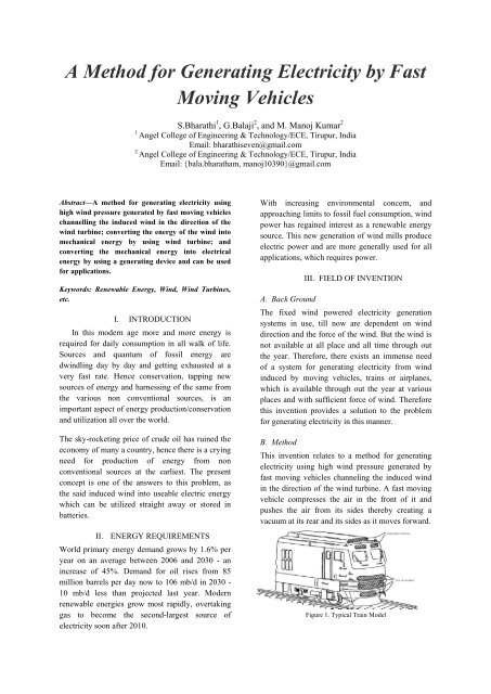
in the direction of the wind turbine. A <strong>fast</strong> <strong>moving</strong><br />
vehicle <strong>com</strong>presses the air in the front of it and<br />
pushes the air from its sides there<strong>by</strong> creating a<br />
vacuum at its rear and its sides as it moves <strong>for</strong>ward.<br />
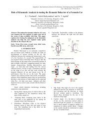
Figure 1. Typical Train Model
The kinetic energy of the wind movement thus<br />
created can be used to generate <strong>electricity</strong>. The<br />
<strong>moving</strong> <strong>vehicles</strong> encounters wind may be railway<br />
trains or airplanes, will sweep off it, in a <strong>fast</strong>er<br />
manner making heavy winds.<br />
During this, when a wind turbine, if fit to the<br />
<strong>moving</strong> vehicle will generate adequate amount of<br />
energy. The air flow will cause turbine to rotate and<br />
thus <strong>electricity</strong> can be produced.<br />
IV. OBJECTS OF THE INVENTION<br />
The main object of the present invention is to<br />
provide a <strong>method</strong> and a system <strong>for</strong> <strong>generating</strong><br />
<strong>electricity</strong> using easily available wind induced <strong>by</strong><br />
<strong>moving</strong> <strong>vehicles</strong>/airplanes in transit or in operation.<br />
The other object of the invention is to provide a<br />
<strong>method</strong> and a system <strong>for</strong> <strong>generating</strong> <strong>electricity</strong> <strong>by</strong><br />
using high wind pressure generated <strong>by</strong> <strong>moving</strong><br />
<strong>vehicles</strong>, using this free renewable input namely air<br />
and independent of the vagaries of seasonal winds<br />
having the variation in direction and wind speeds<br />
when they do flow and that too neither at all times<br />
or places nor having the necessary <strong>for</strong>ce of wind to<br />
operate wind mill to generate <strong>electricity</strong> as<br />
required.<br />
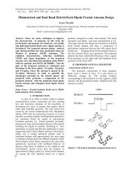
off. These induces <strong>fast</strong> winds in all it direction of<br />
propagation.<br />
B. Routing the induced wind in the direction of the<br />
wind turbine<br />
If the wind is properly directed towards the wind<br />
turbine blades, optimum <strong>electricity</strong> may be<br />
generated. The desired direction of wind is<br />
obtained <strong>by</strong> a means <strong>for</strong> channelling wind, in the<br />
direction of the wind turbine. Channeling of wind<br />
in a desired direction may be obtained <strong>by</strong>, at least<br />
one truncated cone or pyramid shaped housing or a<br />
pair of planar members converging towards the<br />
blades of the wind turbine.<br />
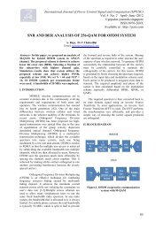
Aerodynamics is the science and study of the<br />
physical laws of the behavior of objects in an air<br />
flow and the <strong>for</strong>ces that are produced <strong>by</strong> air flows.<br />
The shape of the aerodynamic profile is decisive<br />
<strong>for</strong> blade per<strong>for</strong>mance. Even minor alterations in<br />
the shape of the profile can greatly alter the power<br />
curve and noise level. There<strong>for</strong>e a blade designer<br />
does not merely sit down and outline the shape<br />
when designing a new blade.<br />
V. DESCRIPTION OF INVENTION<br />
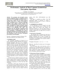
Figure 3. Aerodynamics of Wind<br />
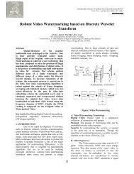
Figure 2. Basic flow diagram<br />
A. Capturing wind induced <strong>by</strong> <strong>moving</strong> <strong>vehicles</strong><br />
The <strong>moving</strong> <strong>vehicles</strong> may be all types of light or<br />
heavy <strong>vehicles</strong> running on road, such as two, three,<br />
four wheelers or even bigger <strong>vehicles</strong>. The <strong>moving</strong><br />
<strong>vehicles</strong> could be railway train running on railway<br />
track. The <strong>vehicles</strong> could also be aircraft <strong>moving</strong><br />
on to the runway, taking off or landing; when<br />
testing the propellers in the workshops, proceeding<br />
to or standing <strong>by</strong>e in the holding area be<strong>for</strong>e taking<br />
The aerodynamic profile is <strong>for</strong>med with a rear side,<br />
is much more curved than the front side facing the<br />
wind. Two portions of air molecules side <strong>by</strong> side in<br />
the air flow <strong>moving</strong> towards the profile at point A<br />
will separate and pass around the profile and will<br />
once again be side <strong>by</strong> side at point B after passing<br />
the profile‟s trailing edge. As the rear side is more<br />
curved than the front side on a wind turbine blade,<br />
this means that the air flowing over the rear side<br />
has to travel a longer distance from point A to B<br />
than the air flowing over the front side. There<strong>for</strong>e<br />
this air flow over the rear side must have a higher<br />
velocity if these two different portions of air shall<br />
be reunited at point B. Greater velocity produces a<br />
pressure drop on the rear side of the blade, and it is
this pressure drop that produces the lift. The<br />
highest speed is obtained at the rounded front edge<br />
of the blade.<br />
The blade is almost sucked <strong>for</strong>ward <strong>by</strong> the pressure<br />
drop resulting from this greater front edge speed.<br />
There is also a contribution resulting from a small<br />
over-pressure on the front side of the blade.<br />
Compared to an idling blade the aerodynamic<br />
<strong>for</strong>ces on the blade under operational conditions are<br />
very large. Most wind turbine owners have surely<br />
noticed these <strong>for</strong>ces during a start-up in good wind<br />
conditions.<br />
The wind turbine will start to rotate very slowly at<br />
first, but as it gathers speed it begins to accelerate<br />
<strong>fast</strong>er and <strong>fast</strong>er. The change from slow to <strong>fast</strong><br />
acceleration is a sign that the blade‟s aerodynamic<br />
shape <strong>com</strong>es into play, and that the lift greatly<br />
increases when the blade meets the head wind of its<br />
own movement.The <strong>fast</strong> acceleration, near the wind<br />
turbine‟s operational rotational speed, places great<br />
demands on the electrical cut-in system that must<br />
capture and engage the wind turbine without<br />
releasing excessive peak electrical loads to the grid.<br />
C. Converting the energy of the wind into<br />
mechanical energy <strong>by</strong> using wind turbine<br />
There are two primary physical principles <strong>by</strong> which<br />
energy can be extracted from the wind. These are<br />
through the creation of either lift or drag <strong>for</strong>ce (or<br />
through a <strong>com</strong>bination of the two).<br />
Drag <strong>for</strong>ces provide the most obvious means of<br />
propulsion, these being the <strong>for</strong>ces felt <strong>by</strong> a person<br />
(or object) exposed to the wind. Lift <strong>for</strong>ces are the<br />
most efficient means of propulsion but being more<br />
subtle than drag <strong>for</strong>ces are not so well understood.<br />
Lift is primary due to the physical phenomena<br />
known as Bernoulli‟s Law. This physical law states<br />
that when the speed of an air flow over a surface is<br />
increased the pressure will then drop. This law is<br />
counter to what most people experience from<br />
walking or cycling in a head wind, where normally<br />
one feels that the pressure increases when the wind<br />
also increases. This is also true when one sees an<br />
air flow blowing directly against a surface, but it is<br />
not the case when air is flowing over a surface. One<br />
can easily convince oneself that this is so <strong>by</strong><br />
making a small experiment.<br />
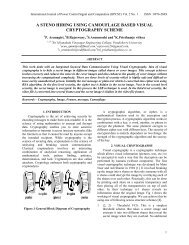
Figure 5. Bernoulli‟s Law<br />
Figure 4. Rotation of rotor<br />
The desired direction may be transverse or parallel<br />
to the direction of plane of rotation of blades<br />
depending upon the type of wind turbine used or<br />
the direction of wind, or it the design of the wind<br />
turbines. The turbines are connected to <strong>electricity</strong><br />
generator to generate <strong>electricity</strong>. The generated<br />
<strong>electricity</strong> may be used directly or stored in<br />
batteries which can be used at the time of need.<br />
Take two small pieces of paper and bend them<br />
slightly in the middle. Then hold them as shown in<br />
the diagram and blow in between them. The speed<br />
of the air is higher in between these two pieces of<br />
paper than outside (where of course the air speed is<br />
about zero), so there<strong>for</strong>e the pressure inside is<br />
lower and according to Bernoulli‟s Law the papers<br />
will be sucked in towards each other.<br />
One would expect that they would be blown away<br />
from each other, but in reality the opposite occurs.<br />
This is an interesting little experiment that clearly<br />
demonstrates a physical phenomenon that has a<br />
<strong>com</strong>pletely different result than what one would<br />
expect.
D. Converting that mechanical energy into<br />
electrical energy <strong>by</strong> using a <strong>generating</strong> device<br />
The generator is the unit of the wind turbine that<br />
trans<strong>for</strong>ms mechanical energy into electrical<br />
energy. The blades transfer the kinetic energy from<br />
the wind into rotational energy in the transmission<br />
system, and the generator is the next step in the<br />
supply of energy from the wind turbine to the<br />
electrical grid.<br />
The wind turbine may be connected to an<br />
<strong>electricity</strong> generator. The generated <strong>electricity</strong> may<br />
to be stored in pluralities of batteries from which<br />
energy may be used as per the need.<br />
These turbines have been designed to power small<br />
units like <strong>com</strong>partments of train, recharging<br />
batteries, although we should mention that it is also<br />
quite easy to imagine how a specially designed<br />
wind turbine like this could sit on top of the train or<br />
at front and power its engine as you cruise along on<br />
the rail/road. This wind turbine was developed to<br />
be used as an alternative means to recharge<br />
<strong>com</strong>munications equipment too.<br />
VI. POWER PRODUCTION<br />
1) The kinetic energy of wind<br />
The kinetic energy of the wind is the source of the<br />
driving <strong>for</strong>ce of a wind turbine.<br />
That kinetic energy can be depicted <strong>by</strong> the <strong>for</strong>mula<br />
E = f. mspec .v3<br />
In this <strong>for</strong>mula:<br />
E = the kinetic energy<br />
mspec =the specific mass (weight) of air<br />
v = the velocity of the <strong>moving</strong> air (the wind)<br />
f = a calculating factor without any physic meaning<br />
The power in the wind is proportional to:<br />
a) the area of windmill being swept <strong>by</strong> the wind<br />
b) the cube of the wind speed<br />
c) the air density - which varies with altitude.<br />
The <strong>for</strong>mula used <strong>for</strong> calculating the power in the<br />
wind is shown below:<br />
Power = (density of air x swept area x velocity<br />
cubed)/2<br />
P = ½. ρ(A)(V) 3<br />
Where,<br />
P is power in watts (W)<br />
ρ is the air density in kilograms per cubic metre<br />
(kg/m3)<br />
A is the swept rotor area in square metres (m2) &<br />
V is the wind speed in metres per second (m/s).<br />
VII. COST ECONOMICS<br />
However, the power output from the wind machine<br />
is proportional to cube of the wind speed and so a<br />
increase in wind speed will mean a significant<br />
increase in power and a subsequent reduction in<br />
unit costs.<br />
VIII.<br />
ADVANTAGES<br />
There are 14,300 trains operating daily on 63,000<br />
route kilometers of railway in India. This technique<br />
would be capable of producing 1,481,000 megawatt<br />
(MW) of power in India alone.<br />
There are some specially designed wind turbines.<br />
Traditionally wind turbines have three-blade, „open<br />
rotor‟ design.<br />
A <strong>com</strong>mon <strong>method</strong> of this design is that even small<br />
turbines require a <strong>fast</strong> wind be<strong>for</strong>e they start<br />
operating. Small turbines can be used to generate<br />
more power and can be used <strong>for</strong> <strong>com</strong>mercial<br />
applications as we store the retrieved energy in<br />
batteries.<br />
CONCLUSIONS<br />
There are huge potential <strong>for</strong> producing<br />
<strong>electricity</strong> from renewable sources.<br />
The achievement so far is about<br />
10406.69 MW, as against global<br />
installed capacity of approximately<br />
200000 MW of renewable <strong>electricity</strong><br />
generation.<br />
With this <strong>method</strong>, the whole unit can be<br />
supplied with <strong>electricity</strong> <strong>for</strong> lighting,<br />
fans etc.<br />
The technology is expected to contribute<br />
to the cause of the environment as it<br />
helps to reduce carbon emissions and<br />
also assists the government in saving<br />
on fuel too…<br />
ACKNOWLEDGMENT<br />
I wish to thank my staff members <strong>for</strong> their valuable<br />
support in all my aspects and my girl who is<br />
responsible <strong>for</strong> this paper and concept.<br />
REFERENCES<br />
[1] “A <strong>method</strong> <strong>for</strong> <strong>generating</strong> <strong>electricity</strong> <strong>by</strong> capturing<br />
tunnel induced winds” <strong>by</strong> REKHI, Bhupindar, Singh.<br />
[2] C.J. Baker (1986), “Train Aerodynamic Forces and<br />
Moments from Moving Model Experiments”, Journal of<br />
Wind Engineering and Industrial Aerodynamics,<br />
24(1986), 227-251.
[3] Wilson, R.E. and Lissaman, P.B.S., “Applied<br />
Aerodynamics of Wind Power Machines”, NTIS PB<br />
238594, Oregon State University, 1974.<br />
[4] Stephane Sanquer, Christian Barre, Marc Dufresne de<br />
Virel and Louis-Marie Cleon (2004), “Effect of cross<br />
winds on high-speed trains: development of new<br />
experimental <strong>method</strong>ology”, Journal of Wind<br />
Engineering and Industrial Aerodynamics, 92(2004),<br />
535-545.