

Hoffmann 3 Operative Technique - Stryker
Hoffmann 3 Operative Technique - Stryker
Hoffmann 3 Operative Technique - Stryker

You also want an ePaper? Increase the reach of your titles
YUMPU automatically turns print PDFs into web optimized ePapers that Google loves.
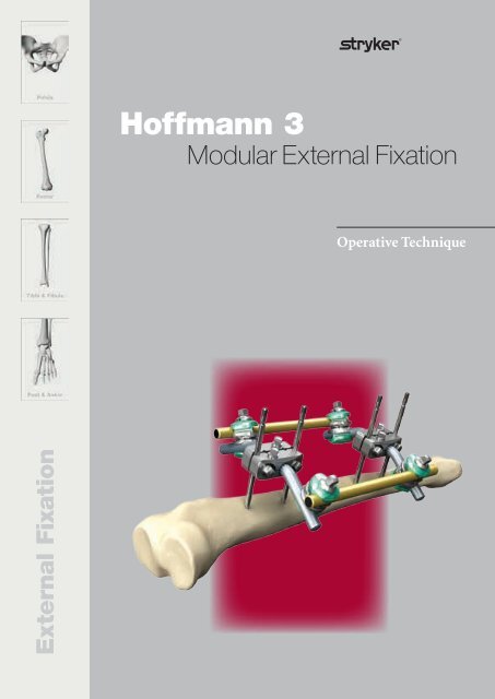
<strong>Hoffmann</strong> 3<br />
Modular External Fixation<br />
<strong>Operative</strong> <strong>Technique</strong><br />
External Fixation<br />
1
<strong>Hoffmann</strong> 3 External Fixation<br />
Acknowledgments<br />
<strong>Stryker</strong> acknowledges the following<br />
surgeons for their support in the<br />
development of this technique guide:<br />
Prof. David Seligson M.D.<br />
Prof. Andrew R. Burgess M.D.<br />
Dr. Greg M. Osgood M.D.<br />
Mr. Christopher T. Andrews, FRCS.<br />
This publication sets forth detailed<br />
recommended procedures for using<br />
<strong>Stryker</strong> Osteosynthesis devices and<br />
instruments.<br />
It offers guidance that you should<br />
heed, but, as with any such technical<br />
guide, each surgeon must consider<br />
the particular needs of each patient<br />
and make appropriate adjustments<br />
when and as required.<br />
A workshop training is recommended<br />
prior to first surgery.<br />
All non-sterile devices must be<br />
cleaned and sterilized before use.<br />
Follow the instructions provided<br />
in our Instructions for Cleaning,<br />
Sterilization, Inspection and<br />
Maintenance (L24002000).<br />
Multi-component instruments must<br />
be disassembled for cleaning. Please<br />
refer to the corresponding assembly/<br />
disassembly instructions.<br />
See package insert (V15011, V15013,<br />
V15034) for a complete list of potential<br />
adverse effects, contraindications,<br />
warnings and precautions.<br />
The surgeon must discuss all relevant<br />
risks, including the finite lifetime<br />
of the device, with the patient,<br />
when necessary.<br />
Warning:<br />
Fixation Screws:<br />
<strong>Stryker</strong> Osteosynthesis bone screws<br />
are not approved or intended for<br />
screw attachment or fixation to the<br />
posterior elements (pedicles) of the<br />
cervical, thoracic or lumbar spine.<br />
2
Contents<br />
Page<br />
1. Introduction 4<br />
2. Indications & Contraindications 6<br />
3. Radiologist Guidelines 7<br />
4. Components 9<br />
5. Frame Examples 16<br />
Tibial Frame 16<br />
Ankle Frames 23<br />
Femur Frames 28<br />
Pelvic Frames 31<br />
Knee Frames 37<br />
Ordering Information 41<br />
Military or Disaster Recovery Kits 45<br />
Sterile Field Kit A 46<br />
Sterilr Field Kit B 51<br />
3
Introduction<br />
In 1938, Raoul <strong>Hoffmann</strong>, a Germanborn<br />
surgeon living and working in<br />
Geneva, Switzerland, set himself the<br />
goal of designing a new way to reduce<br />
and fix broken bones. His objective<br />
was to devise a system that would<br />
utilise an alternative form of fracture<br />
treatment, without reliance on open<br />
surgery. The result was history’s first<br />
fully-functional, mainstream External<br />
Fixation System 1 .<br />
The main features of the newly<br />
born <strong>Hoffmann</strong> apparatus were its<br />
modular design, its ability to realign,<br />
reduce and fix fractures and the<br />
pioneering aptitude for making intra<br />
and postoperative corrections in all<br />
three planes with the frame in situ1.<br />
<strong>Hoffmann</strong>’s closed reduction technique<br />
helped establish the very doctrine<br />
for minimally invasive orthopaedic<br />
surgery while laying the foundation<br />
for the Osteotaxis Method, a term that<br />
<strong>Hoffmann</strong> coined himself 1 .<br />
Over the years, the <strong>Hoffmann</strong> System<br />
has evolved considerably. Today’s<br />
completely modular <strong>Hoffmann</strong> 3<br />
remains faithful to the ingenuity of its<br />
inventor.<br />
The <strong>Hoffmann</strong> 3 is a modular,<br />
multiplanar External Fixation System<br />
with independent pin placement<br />
capabilities, patented 6 , rapid<br />
assembly Snap-Fit Couplings and<br />
MR Conditional frame options that<br />
are designed to adapt freely to the<br />
anatomy to form constructs of high<br />
stability for the management of trauma<br />
and correction of deformities. It is<br />
comprised of a handful of key elements<br />
that work in precise agreement to<br />
enable surgeons to create a wide variety<br />
of frames that allow unhindered access<br />
to damaged tissues, permitting rapid<br />
and effective treatment of numerous<br />
traumatic injuries 2,3 .<br />
The <strong>Hoffmann</strong> 3 is not just an update<br />
to the earlier renditions of this System;<br />
it is the result of comprehensive<br />
engineering that has successfully built<br />
upon and significantly added to the<br />
power, utility and rich legacy of the<br />
previous generations.<br />
In the <strong>Hoffmann</strong> 3 you will find not<br />
just a new look, but a demonstrably<br />
innovative feel to the entire platform<br />
of 11mm based components.<br />
The new generation of fully articulating<br />
Delta Couplings promote enhanced<br />
stability, greater versatility and<br />
unrivalled convenience. The Delta<br />
Couplings feature full compatibility<br />
with <strong>Hoffmann</strong> II MRI and even<br />
<strong>Hoffmann</strong> II Compact MRI. That<br />
means you can use any combination<br />
of 5, 8 and 11mm Connecting Rods in<br />
any construct you build. You can rotate<br />
all of the Couplings independently<br />
to allow numerous provisional<br />
options and the freedom to refine<br />
your construct throughout the entire<br />
surgical procedure.<br />
These same Couplings can be locked<br />
securely once definitive reduction and<br />
fixation have been achieved. A variety<br />
of Pin Clamps allow you to accurately<br />
position each pin while an expanded<br />
selection of straight and angled posts<br />
extends the reach and utility of your<br />
frames. This versatile resource of<br />
components enables you to build entire<br />
constructs that meet the requirements<br />
set forth in ASTM (American Society<br />
for Testing and Materials) Standards<br />
that govern safe usage of medical<br />
devices in MRI environments.<br />
Compliance with these Standards<br />
include all patented 6 Vectran coated<br />
Connecting Rods, making <strong>Stryker</strong><br />
both a pioneer and industry leader<br />
in MR Conditional External Fixation<br />
technology 4,6 .<br />
1. Raoul <strong>Hoffmann</strong> and His External Fixator,<br />
Schwechter, E. M., Swan, K. G.; Published in<br />
J Bone Joint Surg Am, Vol. 89, Issue 3, Pages<br />
672 - 678.<br />
2. The Damage control Orthopedic (DCO)<br />
Footplate: A New Use of the <strong>Hoffmann</strong> II<br />
External Fixation System. Beck, D.J. Seligson,<br />
D. Mereau, T., Published in OsteoTrauma Care<br />
2004, Volume 12, Pages 16 - 19.<br />
3. A Comparison of Two Military Temporary<br />
Femoral External Fixators. LTC Paul J.<br />
Dougherty, MD; CPT Brian Vickaryous, MD;<br />
Edgar Conley, PhD; and Kyle Hickerson,<br />
BS; Published in Clinical Orthopaedics and<br />
Related Research Number 412, Pages 176 -183<br />
4. <strong>Stryker</strong> White Paper; Magnetic Resonance<br />
Imaging Testing of External Fixation Frames:<br />
<strong>Stryker</strong> <strong>Hoffmann</strong> II; J. Nyenhuis, PhD.; School<br />
of Electrical and Computer Engineering,<br />
Purdue University<br />
5. Thermal Response and Torque Resistance<br />
of Five Cortical Half Pins Under Simulated<br />
Insertion <strong>Technique</strong>; Wikenheiser, M.<br />
A., Market, M. D., Lewallen, D. G., et al.,<br />
Published in J. Orthop Res 1995; 13; 615 - 619<br />
6. U.S. Patent Nos.: US752,7626, US5,752,954,<br />
US6,080,153<br />
4
Introduction<br />
MR Conditional<br />
MR The <strong>Hoffmann</strong> 3 was developed for<br />
use in acute trauma, damage control<br />
orthopaedics and definitive fixation<br />
settings and is endowed with a variety<br />
of features that make it simple, fast,<br />
precise and adaptable for many types<br />
of patients, regardless of their size or<br />
build.<br />
You can place pins wherever they<br />
are needed and then build the frame<br />
around them. You can assemble<br />
constructs to suit a variety of fractures,<br />
including those close to a joint, while<br />
easily accommodating the associated<br />
soft tissue envelopes. The patented,<br />
single point of tightening Snap-Fit<br />
technology and simple instrumentation<br />
are designed to enable you to build<br />
stable frames quickly and easily 2,3 .<br />
With the frame in place, minimal effort<br />
is needed to fine-tune the construct<br />
after initial reduction 1 . Rods and<br />
Couplings can be clicked on and off<br />
at any time. These important features<br />
help contain and rapidly stabilise<br />
orthopaedic injuries to allow the<br />
patient’s overall physiology to improve<br />
while providing either temporary or<br />
definitive treatment 4 .<br />
The Third Generation of the <strong>Hoffmann</strong><br />
System has undergone a rigorous<br />
testing protocol to ensure that it<br />
continues the venerable tradition of its<br />
predecessors. In the following pages,<br />
you will find a thorough description<br />
of the <strong>Hoffmann</strong> 3 and a detailed<br />
overview of several commonly utilised<br />
frames using this ground-breaking<br />
System.<br />
<strong>Stryker</strong> is committed to the highest<br />
level of quality, safety and patient<br />
care. The entire <strong>Hoffmann</strong> 3 External<br />
Fixation System (<strong>Hoffmann</strong> 3)<br />
was designed from the ground up<br />
for MR Conditional placement in<br />
MRI environments up to 3.0 Tesla.<br />
<strong>Hoffmann</strong> 3 complies with the<br />
American Society for Testing and<br />
Materials (ASTM) testing requirements<br />
for passive medical devices in the MRI<br />
environments.<br />
For more detailed information please<br />
refer to the specific section in this<br />
operative technique.<br />
1. Raoul <strong>Hoffmann</strong> and His External Fixator, Schwechter, E. M., Swan, K. G.; Published in J Bone Joint<br />
Surg Am, Vol. 89, Issue 3, Pages 672 - 678.<br />
2. The Damage control Orthopedic (DCO) Footplate: A New Use of the <strong>Hoffmann</strong> II External Fixation<br />
System. Beck, D.J. Seligson, D. Mereau, T., Published in OsteoTrauma Care 2004, Volume 12, Pages<br />
16 - 19.<br />
3. A Comparison of Two Military Temporary Femoral External Fixators. LTC Paul J. Dougherty, MD;<br />
CPT Brian Vickaryous, MD; Edgar Conley, PhD; and Kyle Hickerson, BS; Published in Clinical<br />
Orthopaedics and Related Research Number 412, Pages 176 -183<br />
4. <strong>Stryker</strong> White Paper; Magnetic Resonance Imaging Testing of External Fixation Frames: <strong>Stryker</strong><br />
<strong>Hoffmann</strong> II; J. Nyenhuis, PhD.; School of Electrical and Computer Engineering, Purdue University<br />
5
Indications & Contraindications<br />
Intended Use<br />
The <strong>Hoffmann</strong> 3 Modular External<br />
Fixation System is used to provide<br />
stabilization of open and/or unstable<br />
fractures and where soft tissue injury<br />
may preclude the use of other fracture<br />
treatments such as IM rods, casts,<br />
or other means of internal fixation.<br />
Indications<br />
The <strong>Hoffmann</strong> 3 Modular External<br />
Fixation System components are<br />
external fixation frame components<br />
for use with the components of the<br />
<strong>Hoffmann</strong> II MRI and <strong>Hoffmann</strong><br />
II Compact MRI External Fixation<br />
Systems, in conjunction with Apex<br />
Pins. It is intended to provide<br />
stabilization of open and/or unstable<br />
fractures and where soft tissue<br />
precludes the use of other fracture<br />
treatments such as IM nailing or<br />
casting or other means of internal<br />
fixation.<br />
The indications for use of external<br />
fixation devices include:<br />
• Bone Fracture Fixation<br />
• Osteotomy<br />
• Arthrodesis<br />
• Correction of deformity<br />
• Revision procedure where other<br />
treatments or devices have been<br />
unsuccessful<br />
• Bone reconstruction procedures<br />
Contraindications<br />
See package insert for warnings<br />
and precautions.<br />
6
Radiologist Guidelines<br />
MR Conditional<br />
<strong>Stryker</strong> is committed to the highest<br />
level of quality, safety and patient<br />
care. The entire <strong>Hoffmann</strong> 3 External<br />
Fixation System (<strong>Hoffmann</strong> 3) was<br />
designed from the ground up for<br />
MR Conditional placement in MRI<br />
environments.<br />
<strong>Hoffmann</strong> 3 complies with the<br />
American Society for Testing<br />
and Materials (ASTM 1 ) testing<br />
requirements for passive medical<br />
devices in the MRI environments.<br />
MR Conditional<br />
<strong>Stryker</strong> utilizes a systems approach to<br />
address two key areas of concern in<br />
MRI use:<br />
(1) frame displacement and<br />
(2) frame heating.<br />
To address these concerns, <strong>Hoffmann</strong> 3<br />
is designed with non-ferromagnetic<br />
materials and insulated carbon rods:<br />
• Clamps & couplings are made<br />
from aluminum, austenitic steel and<br />
titanium<br />
• Apex® Half Pins and Posts are made<br />
from austenitic steel and aluminum<br />
• Carbon-Fiber Rods are coated with<br />
an electrically insulating coating,<br />
Vectran®<br />
Since <strong>Hoffmann</strong> 3 components are<br />
non-magnetic, magnetic fields in the<br />
MRI environment will not displace<br />
the frame nor pose a risk of magnetic<br />
injury to patients or damage to<br />
the scanner if used under proper<br />
conditions.<br />
MRI Components<br />
MR Conditional<br />
The MRI components have been tested according to ASTM Standards F2052, F2119, F2182, and F2213.<br />
The <strong>Hoffmann</strong> 3 MRI System can only be guaranteed for MRI use when using <strong>Stryker</strong>’s Apex Pins to build a frame.<br />
4922-1-010 4922-1-020 4922-1-030 4922-1-015<br />
4922-1-025<br />
4921-2-060<br />
4922-2-020 4922-2-020<br />
4922-2-320 4922-2-220 4922-1-220 4922-2340<br />
4922-2-240<br />
4922-8-XXX 4922-7-220<br />
4922-2-120<br />
4922-2-140<br />
4922-2-160<br />
Note:<br />
Frame tests have been performed 2 in areas where the greatest temperature increase is expected with commonly used frames. Due to the versatility<br />
of the system, an unlimited number of frames can be built which makes it impossible to test each and every construct. Based on the test results, the<br />
<strong>Hoffmann</strong> 3 may be used in MRI procedures under the specified conditions. There are factors that can influence these results like the number of pins<br />
used in the clamps and the number of open and closed loops in the frame. Therefore, it is recommended that each frame be evaluated by a radiologist or<br />
MR scientist before the MRI procedure to ensure patient safety. Since different frame configurations and frame sizes might lead to higher temperature<br />
increases, <strong>Stryker</strong> recommends for patient’s safety to minimize SAR settings as much as possible. Non-clinical testing has been performed to rule<br />
out the possibility of component movement or migration at static magnetic field strengths higher than 3.0 Tesla or maximum spatial gradients higher<br />
than 90.0 mT/cm. MR image quality may be compromised if the area of interest is in the exact same area as or approx. 10cm under worst case conditions<br />
to the position of the frame or its individual components.<br />
1<br />
ASTM F2503-08: http://www.astm.org/Standards/F2503.htm<br />
2<br />
Based upon Biomechanical Lab Reports: BML 11-066, BML 11-270, BML 12-061, BML 12-062, <strong>Stryker</strong> in Selzach, Switzerland<br />
7
Radiologist Guidelines<br />
It has been shown by specific MRI tests 2 that the <strong>Hoffmann</strong> 3 External Fixation System may be used for patients undergoing<br />
MRI procedures using up to 3.0 Tesla MR systems if certain specific conditions are met. The following frames have been tested<br />
in 1.5 Tesla and with 2 exceptions also in 3.0 Tesla MRI environments. All components are safe with respect to displacement in<br />
an MRI magnetic field with a maximum spatial gradient of 90 mT/cm.<br />
Standard Bilateral Tibia Frame<br />
1.5 Tesla MR System<br />
Δ T max: 4.45°C at 1.0W/kg at a whole body average SAR for MR imaging time of 15 minutes<br />
3.0 Tesla MR System<br />
Δ Tmax: 2.80°C at 0.5W/kg at a whole body average SAR for MR imaging time of 15 minutes<br />
Distal Tibia Shaft Frame with independent pin placement<br />
1.5 Tesla MR System<br />
Δ Tmax: 2.55°C at 1.0W/kg at a whole body average SAR for MR imaging time of 15 minutes<br />
3.0 Tesla MR System – *USE OF OUT OF BODY COIL RECOMMENDED<br />
Δ Tmax: 6.70°C at 0.5W/kg at a whole body average SAR for MR imaging time of 15 minutes<br />
Tibia single rod frame with Multiplanar Delta Coupling<br />
1.5 Tesla MR System<br />
Δ Tmax: 2.8°C at 1.0W/kg at a whole body average SAR for MR imaging time of 15 minutes<br />
3.0 Tesla MR System – Not yet tested at 3.0 Tesla<br />
Femur Emergency Frame with independent pin placement<br />
1.5 Tesla MR System<br />
Δ Tmax: 2.65°C at 1.0W/kg at a whole body average SAR for MR imaging time of 15 minutes<br />
3.0 Tesla MR System – *USE OF OUT OF BODY COIL RECOMMENDED<br />
Δ Tmax: 6.10°C at 0.5W/kg at a whole body average SAR for MR imaging time of 15 minutes<br />
Knee bridging Z-Frame, Independent Pin Placement, with Rod Coupler<br />
1.5 Tesla MR System<br />
Δ Tmax: 1.0°C at 1.0W/kg at a whole body average SAR for MR imaging time of 15 minutes<br />
3.0 Tesla MR System – Not yet tested at 3.0 Tesla<br />
Pelvis Osteotaxis Frame with Multi-Iliac Crest<br />
pin placement<br />
1.5 Tesla MR System<br />
Δ Tmax: 2.65°C at 1.0W/kg at a whole body average SAR for MR imaging time of 15 minutes<br />
3.0 Tesla MR System<br />
Δ Tmax: 4.70°C at 0.5W/kg at a whole body average SAR for MR imaging time of 15 minutes<br />
Pelvis Osteotaxis Frame with independent Iliac<br />
Crest pin placement<br />
1.5 Tesla MR System<br />
Δ Tmax: 1.20°C at 1.0W/kg at a whole body average SAR for MR imaging time of 15 minutes<br />
3.0 Tesla MR System – *USE OF OUT OF BODY COIL RECOMMENDED<br />
Δ Tmax: 7.60°C at 0.5W/kg at a whole body average SAR for MR imaging time of 15 minutes<br />
Tests have been performed using a MR system for a max. image time of 15 minutes. Please note that the Specific Absorption<br />
Rate (SAR) may be reported differently, e.g. as whole body averaged SAR or as partial SAR by the software depending on the<br />
MR system used.<br />
* ∆Tmax
Components<br />
Delta Couplings<br />
Design features for easy frame assembly:<br />
• Pre-assembled Thumbwheel for provisional tightening<br />
• Three dimensional rotation<br />
• Patented Snap-fit technology *<br />
Delta Coupling, Rod-to-Rod<br />
or Pin-to-Rod<br />
The Rod-to-Rod Delta Couplings<br />
can snap onto Ø5, Ø8 or Ø11mm<br />
Connecting Rods and Ø5mm Apex<br />
Pins**. Rod-to-Rod Delta Couplings<br />
are color coded green/green.<br />
Delta Coupling, Pin-to-Rod<br />
The Pin-to-Rod Delta Couplings are<br />
designed to fit onto a choice of Ø5, Ø8<br />
or Ø11mm Connecting Rods and Ø4,<br />
Ø5 or Ø6mm Apex Pins. Pin-to-Rod<br />
Delta Couplings are color coded grey/<br />
green.<br />
Delta Coupling, Pin-to-Rod,<br />
inverted<br />
‘Inverted’ Pin-to-Rod Delta Coupling<br />
are available with the bolt on opposite<br />
side to facilitate easy tightening when<br />
required by special frame construct<br />
accessibility. ‘Inverted’ Pin-to-Rod Delta<br />
Couplings are color coded green/grey.<br />
* Patent No’s US5,752,954 and US6,080,153<br />
** Note: Standardization with one coupling may be achieved by utilizing<br />
a Rod-to-Rod Delta Coupling with Ø8mm or Ø11mm Connecting Rod<br />
and 5mm Apex Pins or 3/5mm, 4/5mm Hybrid Apex Pins.<br />
9
Components<br />
Delta Couplings<br />
Delta Coupling, Rod-to-Rod,<br />
multiplanar<br />
The multiplanar Rod-to-Rod Delta<br />
Coupling is designed to snap onto<br />
a choice of Ø5, Ø8 or Ø11mm<br />
Connecting Rods and/or Ø5mm Apex<br />
Pins on each side of the joint.<br />
The planar joint allows for 180<br />
degrees of motion and 360 degrees of<br />
rotation and with that offers additional<br />
flexibility in frame construction.<br />
Multiplanar Delta Couplings are<br />
color coded green/green and include<br />
two pre-assembled Thumbwheels for<br />
provisional tightening.<br />
Delta Coupling, Pin-to-Rod,<br />
multiplanar<br />
The multiplanar Pin-to-Rod Delta<br />
Coupling is designed to snap onto<br />
a choice of Ø5, Ø8 or Ø11mm<br />
Connecting Rods and Ø4, Ø5 or<br />
Ø6mm Apex Pins on each side of the<br />
joint.<br />
The planar joint allows for 180<br />
degrees of motion and 360 degrees of<br />
rotation and with that offers additional<br />
flexibility in frame construction.<br />
Multiplanar Delta Couplings, Pinto-Rod<br />
are color coded grey/green<br />
and include two pre-assembled<br />
Thumbwheels for provisional<br />
tightening.<br />
For easier reduction of the fracture<br />
and flexible adjustment of the frame<br />
the multiplanar Delta Couplings<br />
can be tightened on one side while<br />
keeping full rotational flexibility and<br />
adjustability on the other side.<br />
The distance between the bars or pins<br />
can be varied from 0 to 37mm allowing<br />
very flexible frame construction and<br />
adjustment.<br />
10
Components<br />
Provisional Tightening<br />
Step 1<br />
Snap two Rods (or a Pin and a Rod)<br />
into a Delta Coupling.<br />
Step 2<br />
Provisionally tighten the Coupling to<br />
the Rods using the Thumbwheel.<br />
Step 3<br />
Remove the single-use Thumbwheel<br />
from the Delta Coupling before the<br />
final tightening.<br />
Final Tightening<br />
Should provisional tightening still be<br />
required after single-use Thumbwheel<br />
removal, use the 4920-9-020<br />
Thumbwheel for additional provisional<br />
tightening.<br />
For final tightening use either the T-handle (4920-9-030) or Spanner Wrench<br />
(4920-9-036).<br />
11
Components<br />
5-Hole Pin Clamp<br />
Screws for locking the Posts in place<br />
5 Hole Pin Clamps can be used if<br />
parallel Pin placement is desired.<br />
The clamp can hold up to five Apex<br />
Half Pins, accommodating Ø4, Ø5 or<br />
Ø6mm pins.<br />
• Pin Clamps are secured to the Apex<br />
Pins by tightening the 7mm Square<br />
Head Screws on the side of the Clamp<br />
Posts<br />
Screws for securing Clamps<br />
to the Apex Pins<br />
Straight, 30° or 90° angled Ø11mm<br />
Posts are used along with the Pin<br />
Clamps to provide a compact,<br />
fracture-specific frame.<br />
• Posts are locked into place by<br />
tightening the two 7mm Square Head<br />
Screws on the top of the Clamp<br />
Fixed Post Clamps<br />
5 Hole Pin Clamps with either one or<br />
two straight or 30° angled fixed Posts are<br />
included in the <strong>Hoffmann</strong> 3 platform for<br />
efficient frame construction.<br />
Rod Coupler, 30°<br />
The Rod Couplers are designed to<br />
connect two Ø11mm Connecting Rods<br />
in a fixed angle. They are ideal for long<br />
spanning frames such as knee bridging<br />
frames or pelvic bow creation.<br />
The couplers allow also asymmetric<br />
fixation of the rods, thus allowing for<br />
exact adaptation to the anatomy of the<br />
patient. The window in the coupler<br />
allows for visual control of the depth of<br />
the rods in the clamping area. With that<br />
one can ensure stable connection and<br />
tight fit.<br />
12
Components<br />
5, 8 and 11mm Connecting Rod options<br />
Carbon Fiber Vectran coated<br />
Connecting Rods, 5, 8 and<br />
11mm options<br />
<strong>Stryker</strong> provides electrically insulated<br />
Carbon Rods for MR Conditional use.<br />
The Ø11mm Vectran coated Carbon<br />
Connecting Rods are available in<br />
lengths from 100mm to 650mm.<br />
The Vectran coated Semi Circular Rods<br />
may be used for the fixation of distal<br />
femur or proximal and distal tibia<br />
(see page 21) fragments.<br />
All Vectran coated Carbon Connecting<br />
Rods are intended for Single Patient<br />
Use only. Once used on a patient<br />
they have to be disposed of. Unused<br />
rods can be reprocessed in the<br />
tray according to the cleaning and<br />
sterilization instructions mentioned<br />
in the package insert. Tests have<br />
shown intended performance for<br />
50 reprocessing cycles.*<br />
MR Conditional<br />
MR In addition to the MR Conditional<br />
standard system features, the<br />
<strong>Hoffmann</strong> 3 also offers a number of<br />
Rod options which are MR Unsafe.<br />
Carbon Fiber Connecting Rods,<br />
5 and 8mm options<br />
Uncoated Carbon Rods offer<br />
radiolucency and relative elasticity for<br />
light weight constructs.<br />
Stainless Steel Connecting<br />
Rods, 5 and 8mm options<br />
For fractures requiring more rigidity,<br />
stainless steel 5 & 8mm Rods are<br />
available.<br />
Aluminium Connecting Rods,<br />
8mm option<br />
Aluminium Rods are lightweight and<br />
more elastic than the carbon fiber rods.<br />
Note:<br />
• Carbon fibre material is known to<br />
be effected by steam sterilisation.<br />
<strong>Hoffmann</strong> 3 MR Conditional<br />
rods have been tested for multiple<br />
sterilisation cycles.<br />
• Frames using one or more MR<br />
unsafe components should not be<br />
used in the MR Environment.<br />
MR Conditional<br />
MR Unsafe<br />
* Biomechanical Rest Reports: BML 11-059, BML 12-054<br />
13
Compatible Components<br />
Compression / Distraction Tube<br />
The Compression/Distraction (C/D) Tube may be incorporated into the frame<br />
to allow fine adjustments for fracture reduction. The C/D Tube may be distracted<br />
to a maximum of 45mm. One complete revolution of the 7mm Square Head Screw<br />
equals 1mm displacement. Turn counter-clockwise for Distraction and clockwise for<br />
Compression.<br />
Ø20mm Rod-to-Tube Clamps are used to connect the Compression/Distraction<br />
Tube to 8mm Connecting Rods or Multi-pin Clamp Posts.<br />
The Rod-to-Tube Clamps employ the same non-slip, snap-fit mechanism<br />
as the Pin-to-Rod and Rod-to-Rod Delta Couplings.<br />
Note:<br />
MR conditional information:<br />
Compression/Distraction Tube should be used<br />
OUT OF BODY COIL.<br />
Pelvic Clamp<br />
The Pelvic Clamp is specially designed<br />
to be used with pins placed in the iliac<br />
crest. Since the clamp does not have<br />
dedicated pin grooves, it can clamp<br />
onto pins that are not fully parallel.<br />
10-Hole Pin Clamp<br />
10-Hole Pin Clamps can hold up to<br />
ten 4, 5 or 6mm Apex Half Pins to<br />
build frames tailored to bridging long<br />
distances in the femur or tibia by<br />
increasing stability due to its wide<br />
pin spread.<br />
Note:<br />
All <strong>Hoffmann</strong> II MRI components are mechanically<br />
compatible with the <strong>Hoffmann</strong> 3 Couplings. However, only<br />
the frames shown in this <strong>Operative</strong> <strong>Technique</strong> have been<br />
tested for MR environment.<br />
14
Components<br />
Apex Pin<br />
Four types of half pins are offered in<br />
the system: Blunt/Self-Tapping Half<br />
Pins, Blunt/Cancellous Half Pins,<br />
Self-Drilling/Self-Tapping Half Pins,<br />
and Self-Drilling Transfixing Pins.<br />
Pre-drilling is necessary when using<br />
blunt pins. It is optional to pre-drill<br />
when using selfdrilling pins.<br />
General Guidelines<br />
For Pre-Drilling<br />
• Always pre-drill with a NEW,<br />
sharp drill<br />
• Drill slowly to help prevent<br />
thermal injury<br />
• When placed through an<br />
exposed bone surface irrigating<br />
the interface can reduce heating<br />
• Always use a drill that’s smaller<br />
in diameter than the Apex Half Pin<br />
Self-Drilling Pin<br />
Blunt Pin<br />
Pin<br />
Thread<br />
Diameter<br />
Drill<br />
Bit<br />
Location<br />
Cancellous Pin<br />
Transfixing Pin<br />
3mm<br />
2.2mm<br />
Ulna, Radius,<br />
Wrist, Metacarpal<br />
4mm<br />
3.2 – 3.5mm<br />
Radius, Ulna,<br />
Humerus,<br />
Tibia, Metatarsal<br />
5mm<br />
4.0 – 4.5mm<br />
Tibia, Femur,<br />
Calcaneus, Pelvis<br />
6mm<br />
4.5 – 5.0mm<br />
Adult Tibia,<br />
Femur, Pelvis<br />
Additional Options<br />
• Stainless steel and titanium<br />
• HA Coating<br />
• Sterile and non sterile packaging<br />
• Hybrid Apex Pins with 3mm thread<br />
diameter and 5mm Shaft, as well as<br />
4mm thread diameter and 5mm Shaft<br />
Note:<br />
For additional information<br />
please refer to the specific Apex<br />
Pin Brochure. Literature Number<br />
LAPFB.<br />
15
Tibial Frames<br />
Pin <strong>Technique</strong> / Safe Zones<br />
• Knowledge of the cross-sectional anatomy of the tibia helps to ensure safe pin placement<br />
• Apex Half Pins can be placed in the medial face of the tibia from plateau to pilon<br />
• Transfixing Pins can be safely placed except in the distal third of the tibia proximal<br />
to the metaphysis and distal to the fibula head near the peroneal nerve<br />
• Before insertion of anterior Apex Half Pins near the ankle joint, perform blunt<br />
dissection to bone to ensure safety of neurovascular bundle<br />
Cut A.<br />
Superficial peroneal nerve<br />
Deep peroneal nerve<br />
Cut B.<br />
Anterior tibial artery<br />
Cut C.<br />
A. B. C.<br />
16
Tibial Frames<br />
Tibial Single Rod Frame<br />
Independent Pin Placement, with multiplanar Delta Couplings<br />
Components List<br />
REF Description Quantity<br />
4922-1-025 Pin-to-Rod Delta Coupling, multiplanar 2<br />
4922-1-020 Pin-to-Rod Delta Coupling 2<br />
5018-5-150 Apex Pin Ø5 x 150mm 4<br />
4922-8-300 Connecting Rods Ø11 x 300mm 1<br />
17
Tibial Frames<br />
Tibial Standard Bi-lateral Frame<br />
Parallel Pin Placement<br />
Components List<br />
REF Description Quantity<br />
4922-2-020 5-Hole Pin Clamp 2<br />
4922-2-140 30° Angled Post Ø11mm 4<br />
4922-1-010 Rod-to-Rod Delta Coupling 4<br />
5018-5-150 Apex Pin Ø5 x 150mm 4<br />
4922-8-300 Connecting Rods Ø11 x 300mm 2<br />
Note:<br />
Alternatively the Pin-to-Rod Delta Couplings can be replaced by mulitplanar<br />
Pin-to-Rod Delta Couplings, thus offering more flexibility and freedom when<br />
placing the Apex Pins and when reducing the fracture before final tightening.<br />
18
Tibial Frames<br />
Tibial Standard Osteotaxis Half Frame<br />
Parallel Pin Placement<br />
Components List<br />
REF Description Quantity<br />
4922-2-020 5-Hole Pin Clamp 2<br />
4922-2-140 30° Angled Post Ø11mm 2<br />
4922-1-010 Rod-to-Rod Delta Coupling 2<br />
5018-5-150 Apex Pin Ø5 x 150mm 4<br />
4922-8-300 Connecting Rods Ø11 x 300mm 1<br />
19
Tibial Frames<br />
Tibial Plateau Semi-Circular Frame<br />
Parallel/Independent Pin Placement<br />
Components List<br />
REF Description Quantity<br />
4922-2-020 5-Hole Pin Clamp 1<br />
4922-2-140 30° Angled Post Ø11mm 2<br />
4922-1-010 Rod-to-Rod Delta Coupling 5<br />
4922-1-020 Pin-to-Rod Delta Coupling 2<br />
4922-1-030 Pin-to-Rod Delta Coupling, inverted 2<br />
5018-5-150 Apex Pin Ø5 x 150mm 5<br />
4922-7-220 Semi Circular Rod Ø11 x 220mm 1<br />
4922-8-300 Connecting Rods Ø11 x 300mm 3<br />
20
Tibial Frames<br />
Distal Tibia Semi-Circular Frame<br />
Parallel/Independent Pin Placement<br />
Components List<br />
REF Description Quantity<br />
4922-2-020 5-Hole Pin Clamp 1<br />
4922-2-140 30° Angled Post Ø11mm 2<br />
4922-1-010 Rod-to-Rod Delta Coupling 4<br />
4922-1-020 Pin-to-Rod Delta Coupling 3<br />
4922-1-030 Pin-to-Rod Delta Coupling inverted<br />
(alternatively 1)<br />
5018-5-150 Apex Pin Ø5 x 150mm 5<br />
5028-7-030 Semi-Circular Rod Ø8mm 1<br />
4922-8-300 Connecting Rods Ø11 x 300mm 2<br />
21
Tibial Frames<br />
Distal Tibia Shaft Frame<br />
Parallel / Independent Pin Placement<br />
Components List<br />
REF Description Quantity<br />
4922-2-020 5-Hole Pin Clamp 1<br />
4922-2-140 30° Angled Post Ø11mm 2<br />
4922-1-010 Rod-to-Rod Delta Coupling 2<br />
4922-1-020 Pin-to-Rod Delta Coupling 2<br />
5018-5-150 Apex Pin Ø5 x 150mm 4<br />
4922-8-250 Connecting Rods Ø11 x 250mm 2<br />
22
Ankle Frames<br />
Pin <strong>Technique</strong> / Safe Zones<br />
• Proximal to the ankle Half-pins can be placed from the medial to lateral in the<br />
anteromedial face of the tibia<br />
• Distal to the crossing of the anterior tibial vessels just proximal to the ankle<br />
transfixing pins are also safe<br />
• Before insertion of anterior Apex Half Pins near ankle joint, perform blunt dissection<br />
to bone to ensure safety of neurovascular bundle<br />
• Transfixation pins are placed through the calcaneus from medial to lateral<br />
Cut A.<br />
A.<br />
23
Ankle Frames<br />
Ankle Cross Brace Frame<br />
Independent Pin Placement<br />
Components List<br />
REF Description Quantity<br />
5018-5-150 Apex Pin Ø5 x 150mm 1<br />
5018-3-180 Apex Pin Ø5 x 180mm 1<br />
5023-3-090 Apex Pin Ø4 x 90mm 1<br />
5030-5-200 Transfixing Pin Ø5/4 x 200mm 1<br />
4922-1-010 Rod-to-Rod Delta Coupling 5<br />
4922-1-020 Pin-to-Rod Delta Coupling 3<br />
4922-1-030 Pin-to-Rod Delta Coupling inverted 2<br />
4922-8-350 Connecting Rods Ø11 x 350mm 2<br />
4922-8-200 Connecting Rods Ø11 x 200mm 3<br />
24
Ankle Frames<br />
Ankle Bridging Frame<br />
Parallel Pin Placement<br />
Components List<br />
REF Description Quantity<br />
4922-2-020 5-Hole Pin Clamp 3<br />
4922-2-140 30° Angled Post Ø11mm 2<br />
4922-2-120 Straight Post Ø11mm 2<br />
4922-1-010 Rod-to-Rod Delta Coupling 4<br />
5018-5-150 Apex Pin Ø5 x 150mm 2<br />
5030-5-200 Transfixing Pin Ø5/4 x 200mm 2<br />
4922-8-250 Connecting Rods Ø11 x 250mm 2<br />
25
Ankle Frames<br />
Ankle Bridging Half Frame<br />
Parallel / Independent Pin Placement<br />
Components List<br />
REF Description Quantity<br />
5018-5-150 Apex Pin Ø5 x 150mm 3<br />
5023-3-090 Apex Pin Ø4 x 90mm 1<br />
4922-1-010 Rod-to-Rod Delta Coupling 3<br />
4922-1-020 Pin-to-Rod Delta Coupling 4<br />
4922-8-300 Connecting Rods Ø11 x 300mm 1<br />
4922-8-150 Connecting Rods Ø11 x 150mm 2<br />
Note:<br />
Alternatively, a second pin can be placed in the calcaneus.<br />
26
Ankle Frames<br />
Ankle Stabilization Frame<br />
Independent Pin Placement<br />
Components List<br />
REF Description Quantity<br />
5018-5-150 Apex Pin Ø5 x 150mm 2<br />
5023-3-090 Apex Pin Ø4 x 90mm 1<br />
4922-1-010 Rod-to-Rod Delta Coupling 3<br />
4922-1-020 Pin-to-Rod Delta Coupling 3<br />
4922-8-250 Connecting Rods Ø11 x 250mm 2<br />
4922-8-100 Connecting Rods Ø11 x 100mm 1<br />
27
Femur Frames<br />
Pin <strong>Technique</strong> / Safe Zones<br />
• In the femur half-pins placed from lateral to medial are safe the entire length of<br />
the bone<br />
• Transfixing pins can be placed in the distal quarter of the femur distal to the<br />
passage of the femoral artery posteriorly<br />
Cut A.<br />
Cut B.<br />
Cut C.<br />
A. B. C.<br />
28
Femur Frames<br />
Femur Bi-Lateral Frame (Double Half Frame)<br />
Parallel Pin Placement<br />
Components List<br />
REF Description Quantity<br />
4922-2-020 5-Hole Pin Clamp 2<br />
4922-2-140 30° Angled Post Ø11mm 4<br />
4922-1-010 Rod-to-Rod Delta Coupling 4<br />
5021-6-180 Apex Pin Ø6 x 180mm 6<br />
4922-8-350 Connecting Rods Ø11 x 350mm 2<br />
29
Femur Frames<br />
Femur Emergency Frame<br />
Independent Pin Placement<br />
Components List<br />
REF Description Quantity<br />
4922-1-020 Pin-to-Rod Delta Coupling 4<br />
4922-1-010 Rod-to-Rod Delta Coupling 2<br />
5021-6-180 Apex Pin Ø6 x 180mm 4<br />
4922-8-350 Connecting Rods Ø11 x 350mm 3<br />
Note:<br />
Apply additional pins and rods<br />
before patient transportation.<br />
30
Pelvic Frames<br />
Pin <strong>Technique</strong> / Safe Zones<br />
• Pins can be placed percutaneously in the iliac wings<br />
• Pins can be placed in the pelvis in the crest between the<br />
anterior-superior and anterior inferior iliac spines<br />
31
Pelvic Frames<br />
Pelvic Emergency Frame<br />
Single Supra-acetabular Pin Placement<br />
Components List<br />
REF Description Quantity<br />
4922-1-020 Pin-to-Rod Delta Coupling 2<br />
5021-8-200 Apex Pin Ø6 x 200mm 2<br />
4922-8-400 Connecting Rods Ø11 x 400mm 1<br />
32
Pelvic Frames<br />
Pelvic Osteotaxis Frame<br />
Multi-Iliac Crest Pin Placement<br />
Components List<br />
REF Description Quantity<br />
4921-2-080 Pelvic Pin Clamp 2<br />
4922-1-010 Rod-to-Rod Delta Coupling 7<br />
5018-6-200 Apex Pin Ø5 x 200mm 6<br />
4922-8-350 Connecting Rods Ø11 x 350mm 2<br />
4922-8-400 Connecting Rods Ø11 x 400mm 2<br />
33
Pelvic Frames<br />
Pelvic Osteotaxis Frame<br />
Independent Iliac Crest Pin Placement<br />
Components List<br />
REF Description Quantity<br />
4922-1-030 Pin-to-Rod Delta Coupling, Inverted 4<br />
4922-1-010 Rod-to-Rod Delta Coupling 4<br />
5018-6-200 Apex Pin Ø5 x 200mm 4<br />
4922-8-350 Connecting Rods Ø11 x 350mm 3<br />
4922-8-150 Connecting Rods Ø11 x 150mm 2<br />
34
Pelvic Frame<br />
Pelvic Osteotaxis Frame<br />
Independent Iliac Crest Pin Placement, with Rod Coupler<br />
Components List<br />
REF Description Quantity<br />
4922-1-030 Pin-to-Rod Delta Coupling, inverted 4<br />
4922-1-010 Rod-to-Rod Delta Coupling 2<br />
4922-1-220 Rod Coupler, 30° 1<br />
4922-8-150 Connecting Rod 11 x 150mm 2<br />
4922-8-250 Connecting Rod 11 x 250mm 2<br />
5018-6-180 Apex Pin Ø5 x 180mm 4<br />
35
Pelvic Frames<br />
Pelvic Orthogonal Frame Construct<br />
Perpendicular Iliac Crest / Supra-acetabular Pin Placement<br />
Components List<br />
REF Description Quantity<br />
4922-1-020 Pin-to-Rod Coupling 4<br />
4922-1-010 Rod-to-Rod Coupling 3<br />
5018-6-200 Apex Pin Ø5 x 200mm 4<br />
4922-8-350 Connecting Rods Ø11 x 350mm 2<br />
4922-8-150 Connecting Rods Ø11 x 150mm 2<br />
4922-8-400 Connecting Rods Ø11 x 400mm 1<br />
36
Knee Frames<br />
Pin <strong>Technique</strong> / Safe Zones<br />
• Half-pins are placed in the femur anterolaterally in the shaft<br />
• These are connected to half-pins placed in the anterior-medial face of the tibia<br />
37
Knee Frames<br />
Knee Bridging Frame<br />
Independent Pin Placement, with Rod Coupler<br />
Components List<br />
REF Description Quantity<br />
4922-1-020 Pin-to-Rod Delta Coupling 4<br />
5018-6-180 Apex Pin Ø5 x 180mm 4<br />
4922-1-220 Rod Coupler, 30° 1<br />
4922-8-450 Connecting Rod 11 x 450mm 1<br />
4922-8-350 Connecting Rod 11 x 350mm 1<br />
Note:<br />
Alternatively the Pin-to-Rod Delta Couplings can be replaced by mulitplanar<br />
Pin-to-Rod Delta Couplings, thus offering more flexibility and freedom when<br />
placing the Apex pins and when reducing the fracture before final tightening or,<br />
instead of the Rod Coupler a Rod-to-Rod Delta Coupling could be used.<br />
38
Knee Frames<br />
Knee Bridging Frame<br />
Independent Pin Placement<br />
Components List<br />
REF Description Quantity<br />
4922-1-020 Pin-to-Rod Delta Coupling 4<br />
4922-1-010 Rod-to-Rod Delta Coupling 4<br />
5021-6-180 Apex Pin Ø6 x 180mm 2<br />
5018-6-180 Apex Pin Ø5 x 180mm 2<br />
4922-8-350 Connecting Rods Ø11 x 350mm 4<br />
4922-8-200 Connecting Rods Ø11 x 200mm 1<br />
39
Knee Frames<br />
Knee Bridging Z-Frame<br />
Independent Pin Placement, with Rod Coupler<br />
Components List<br />
REF Description Quantity<br />
4922-1-020 Pin-to-Rod Delta Coupling 4<br />
4922-1-010 Rod-to-Rod Delta Coupling 1<br />
5018-6-180 Apex Pin Ø5 x 180mm 4<br />
4922-1-220 Rod Coupler, 30° 1<br />
4922-8-400 Connecting Rod 11 x 400mm 2<br />
4922-8-250 Connecting Rod 11 x 250mm 1<br />
Note:<br />
Alternatively the Pin-to-Rod Delta Couplings can be replaced by mulitplanar<br />
Pin-to-Rod Delta Couplings, thus offering more flexibility and freedom when<br />
placing the Apex Pins and when reducing the fracture before final tightening.<br />
Or, instead of the Rod Coupler a Rod-to-Rod Delta Coupling could be used.<br />
40
Ordering Information<br />
REF<br />
Description<br />
Delta Couplings<br />
MR Conditional<br />
4922-1-010 Rod-to-Rod Delta Coupling, Ø5/8/11mm Rods and Ø5mm Apex Pins<br />
4922-1-020 Pin-to-Rod Coupling, Ø5/8/11mm Rods and Ø4/5/6mm Apex Pins<br />
4922-1-030 Pin-to-Rod Coupling Inverted, Ø5/8/11mm Rods and Ø4/5/6mm Apex Pins<br />
4922-1-015 Delta Coupling, Rod-to-Rod, multiplanar, Ø5/8/11mm Rods and Ø5mm Apex Pins<br />
4922-1-025 Delta Coupling, Pin-to-Rod, multiplanar, Ø5/8/11mm Rods and Ø4/5/6mm Apex Pins<br />
Tubes<br />
MR Conditional<br />
4921-1-100 Tube-to-Rod Coupling, Ø8mm Rods and Ø20mm Tube<br />
4921-0-000 Dynamization Ø20mm Tube<br />
4921-0-015 Compression/Distraction Ø20mm Tube<br />
Multi-Pin Clamps<br />
MR Conditional<br />
4922-2-020 5-Hole Pin Clamp<br />
4922-2-320 5-Hole Pin Clamp with one Ø11mm Straight Post<br />
4922-2-220 5-Hole Pin Clamp with two Ø11mm Straight Posts<br />
4922-2-340 5-Hole Pin Clamp with one Ø11mm 30 o Angled Post<br />
4922-2-240 5-Hole Pin Clamp with two Ø11mm 30 o Angled Posts<br />
4922-1-220 Rod Coupler, 30°<br />
4921-2-060 10-Hole Pin Clamp<br />
4921-2-080 Pelvic Clamp<br />
41
Ordering Information<br />
REF<br />
Description<br />
Protective End Caps*<br />
MR Conditional<br />
5027-1-040 4mm Apex Pins White<br />
5027-1-050 5mm Apex Pins Blue<br />
*Package Contains 15 units<br />
Posts<br />
MR Conditional<br />
4921-2-120 Straight Post Ø8mm<br />
4921-2-140 30 o Angled Post Ø8mm<br />
4922-2-120 Straight Post Ø11mm<br />
4922-2-140 30 o Angled Post Ø11mm<br />
4922-2-160 90 o Angled Post Ø11mm<br />
Ø11mm MRI Carbon Connecting Rods<br />
Ø8mm MRI Carbon Connecting Rods<br />
4922-8-100 Ø11 x 100mm<br />
MR Conditional<br />
5028-8-065 Ø8 x 65mm<br />
MR Conditional<br />
4922-8-150 Ø11 x 150mm<br />
5028-8-100 Ø8 x 100mm<br />
4922-8-200 Ø11 x 200mm<br />
5028-8-150 Ø8 x 150mm<br />
4922-8-250 Ø11 x 250mm<br />
5028-8-200 Ø8 x 200mm<br />
4922-8-300 Ø11 x 300mm<br />
5028-8-250 Ø8 x 250mm<br />
4922-8-350 Ø11 x 350mm<br />
5028-8-300 Ø8 x 300mm<br />
4922-8-400 Ø11 x 400mm<br />
5028-8-350 Ø8 x 350mm<br />
4922-8-450 Ø11 x 450mm<br />
5028-8-400 Ø8 x 400mm<br />
4922-8-500 Ø11 x 500mm<br />
5028-8-450 Ø8 x 450mm<br />
4922-8-550 Ø11 x 550mm<br />
5028-8-500 Ø8 x 500mm<br />
4922-8-600 Ø11 x 600mm<br />
4922-8-650 Ø11 x 650mm<br />
Ø11mm MRI Semi Circular Rod<br />
MR Conditional<br />
4922-7-220 Semi Circular Rod (Ø11 x 220mm)<br />
Ø8mm MRI Semi Circular Rod<br />
MR Conditional<br />
5028-7-030 Semi Circular Rod (Ø8 x 174mm)<br />
42
Ordering Information<br />
REF<br />
Description<br />
Ø8mm Stainless Steel Connecting Rods<br />
5029-8-065 Ø8 x 65mm<br />
5029-8-100 Ø8 x 100mm<br />
5029-8-150 Ø8 x 150mm<br />
5029-8-200 Ø8 x 200mm<br />
5029-8-250 Ø8 x 250mm<br />
5029-8-300 Ø8 x 300mm<br />
5029-8-350 Ø8 x 350mm<br />
5029-8-400 Ø8 x 400mm<br />
5029-8-450 Ø8 x 450mm<br />
5029-8-500 Ø8 x 500mm<br />
MR Conditional<br />
Ø8mm Aluminium Connecting Rods<br />
5029-8-605 Ø8 x 65mm MR Conditional<br />
5029-8-610 Ø8 x 100mm<br />
5029-8-615 Ø8 x 150mm<br />
5029-8-620 Ø8 x 200mm<br />
5029-8-625 Ø8 x 250mm<br />
5029-8-630 Ø8 x 300mm<br />
5029-8-635 Ø8 x 350mm<br />
5029-8-640 Ø8 x 400mm<br />
5029-8-645 Ø8 x 450mm<br />
5029-8-650 Ø8 x 500mm<br />
5029-7-028 Semi Circular Rod Small (Ø134mm)<br />
5029-7-030 Semi Circular Rod Medium (Ø174mm)<br />
5029-7-032 Semi Circular Rod Large (Ø214mm)<br />
Ø8mm Carbon Rods<br />
5029-8-805 Ø8 x 65mm<br />
5029-8-810<br />
MR Conditional<br />
Ø8 x 100mm<br />
5029-8-815 Ø8 x 150mm<br />
5029-8-820 Ø8 x 200mm<br />
5029-8-825 Ø8 x 250mm<br />
5029-8-830 Ø8 x 300mm<br />
5029-8-835 Ø8 x 350mm<br />
5029-8-840 Ø8 x 400mm<br />
5029-8-845 Ø8 x 450mm<br />
5029-8-850 Ø8 x 500mm<br />
REF<br />
Apex Pins**<br />
Description<br />
MR Conditional<br />
5030-5-250 Transfixing Pin Ø4/5mm, 250 x 50mm<br />
5050-4-300 Transfixing Pin Ø5/6mm, 300 x 40mm<br />
5026-1-150 Self-drilling Hybrid Half Pin Apex Ø4/5mm, 150 x 40mm<br />
5026-8-120 Self-drilling Hybrid Half Pin Apex Ø3/5mm, 120 x 20mm<br />
5015-7-250 Cancellous Half-Pin Apex Ø5/6mm, 250 x 70mm<br />
5023-3-120 Self-drilling Half Pin Apex Ø4mm, 120 x 30mm<br />
5023-5-120 Self-drilling Half Pin Apex Ø4mm, 120 x 35mm<br />
5023-5-150 Self-drilling Half Pin Apex Ø4mm, 150 x 40mm<br />
Note:<br />
For detailed Apex Pin<br />
information refer to Literature<br />
Number LAPFB (for US) or<br />
5075-4-000 (for outside US).<br />
5018-5-120 Self-drilling Half Pin Apex Ø5mm, 120 x 35mm<br />
5018-5-150 Self-drilling Half Pin Apex Ø5mm, 150 x 40mm<br />
5018-5-200 Self-drilling Half Pin Apex Ø5mm, 200 x 50mm<br />
5018-5-250 Self-drilling Half Pin Apex Ø5mm, 250 x 50mm<br />
5018-6-150 Self-drilling Half Pin Apex Ø5mm, 150 x 50mm<br />
5018-6-180 Self-drilling Half Pin Apex Ø5mm, 180 x 50mm<br />
5018-6-200 Self-drilling Half Pin Apex Ø5mm, 200 x 60mm<br />
5018-7-250 Self-drilling Half Pin Apex Ø5mm, 250 x 70mm<br />
5018-8-180 Self-drilling Half Pin Apex Ø5mm, 180 x 60mm<br />
5021-6-180 Self-drilling Half Pin Apex Ø6mm, 180 x 60mm<br />
5021-8-250 Self-drilling Half Pin Apex Ø6mm, 250 x 80mm<br />
43
Ordering Information<br />
<strong>Hoffmann</strong> 3 Instruments and Trays<br />
REF<br />
Description<br />
4920-9-036 7mm Spanner Wrench<br />
4920-9-020 Thumbwheel<br />
4920-9-030 7mm T-Wrench; Ø5/6mm Pin Driver<br />
4936-9-070 7mm Socket Wrench with universal joint (optional)<br />
5085-2-032 Drill 3.2mm for Ø4mm Pins<br />
5085-2-040 Drill 4.0mm for Ø5mm Pins<br />
5085-2-045 Drill 4.5mm for Ø6mm Pins<br />
4922-9-050 Universal Chuck for 4, 5 & 6mm dia. Apex Pins, AO Coupling<br />
4922-9-140 Tissue Protection Sleeve<br />
4922-9-240 Trocar<br />
4922-9-060 Stabilization/ Reduction Wrench<br />
5057-0-300 Drill Brace Assembly<br />
5057-0-310 Handle for Drill Brace<br />
Trays<br />
4922-9-900 Sterilization Metal Tray, empty, including the Lid<br />
1806-9-700 Spare Lid for Metal Tray<br />
4922-9-950 Plastic Tray (for Level 3/4/5 Military or Disaster Recovery Use),<br />
empty, including the Lid<br />
Spare Parts<br />
4922-9-952 Plastic Tray Lid<br />
4922-9-953 Plastic Tray Upper Insert<br />
4922-9-954 Plastic Tray Lower Insert<br />
Sterile Field Kits<br />
4922-9-940S Sterile Field Kit A*<br />
4922-9-941S Sterile Field Kit B*<br />
* For detailed content list and description please refer to the specific section in this<br />
<strong>Operative</strong> <strong>Technique</strong>.<br />
*Note:<br />
For additional information including Drill Guides, Drill Guide Blocks, Drill<br />
Sleeves, Protection Sleeves, Quick Release Apex Chucks, Pin Cutters and more,<br />
please refer to the specific Apex Pin Brochure. Literature Number LAPFB.<br />
44
Military or Disaster Recovery Kits<br />
<strong>Hoffmann</strong> 3 for Military or Disaster Recovery Use<br />
<strong>Hoffmann</strong> External Fixation Systems<br />
have a long tradition providing<br />
solutions not only for patient care<br />
in the established environment of<br />
Trauma Center Infrastructures but<br />
also in extreme situations such as<br />
military operations or disaster recovery<br />
management around the World.<br />
The <strong>Hoffmann</strong> brand has been the<br />
pioneer brand offering sterile packaged<br />
external fixation kits and user friendly<br />
set configurations that allow fracture<br />
treatment or fracture stabilization<br />
either with forward deployed Field Kits,<br />
Level 3/4/5 Military Trays in military<br />
actions or in natural disasters such<br />
as earthquakes, volcanic eruptions,<br />
avalanches, cyclic storms or tsunamis.<br />
In these situations the <strong>Hoffmann</strong> key<br />
features offering a stable, smart and<br />
simple * way to treat injured patients<br />
are crucial.<br />
Universal Vision, Global<br />
Engineering, Swiss Manufacturing<br />
The Third Generation of the <strong>Hoffmann</strong><br />
System has undergone a rigorous design<br />
and testing protocol to ensure that it<br />
continues the venerable tradition of<br />
its predecessors.<br />
In close collaboration with leadership<br />
members of armed forces and disaster<br />
recovery professionals the <strong>Hoffmann</strong> 3<br />
Field Kit A & B were designed to allow<br />
<strong>Stryker</strong> to offer tailored solutions for<br />
those special situations.<br />
The <strong>Hoffmann</strong> 3 Sterile Field Kits A & B<br />
contain scalpels, mosquito clamps,<br />
self-drilling Apex Pins, a manual Drill-<br />
Brace for Pin insertion and frame<br />
tightening, <strong>Hoffmann</strong> 3 Delta Couplings<br />
and Vectran coated Carbon Fibre<br />
Connecting Rods for the temporary<br />
stabilization of diverse fracture patterns.<br />
* White paper: Comparison between the <strong>Hoffmann</strong> II MRI and the <strong>Hoffmann</strong> 3 systems: the mechanical behavior of the connecting rods and a monoplanar<br />
bilateral frame. E. Wobmann, MSc; M. A. Behrens, MSc; S. Brianza, PhD; T. Matsushita, MD, DMSc; D. Seligson, MD; NL11-NA-TR-2465<br />
Based upon Biomechanical Test Reports from <strong>Stryker</strong> Trauma AG, Selzach,Switzerland; BML 11-072 and BML 11-059.<br />
45
Sterile Field Kit A<br />
Components of the <strong>Hoffmann</strong> 3 Sterile Field Kit A (REF. 4922-9-940S):<br />
2 x Delta Coupling, Rod-to-Rod, REF. 4922-1-010<br />
2 x 5-Hole Pin Clamp with one Ø11mm 30° Angled Post, REF. 4922-2-340<br />
1 x Vectran coated Connecting Rod Ø8 x 250mm, REF. 5028-8-250<br />
1 x Vectran coated Connecting Rod Ø11 x 400mm, REF. 4922-8-400<br />
4 x Apex Pin Ø5mm, 180 x 50mm, self-drilling, REF. 5018-6-180<br />
4 x Apex Pin Ø3/5mm, 120 x 20mm, self-drilling, REF. 5026-8-120<br />
1 x Drill Brace for Apex Pins and Couplings / Clamps, REF. VIM-0 *<br />
The Brace accepts Pins on one end and fits over the Clamp / Delta Coupling screws,<br />
on the other end, to function as a wrench.<br />
1 x No.10 Scalpel, REF. SW A-S10 *<br />
1 x Mosquito Hemostat Clamp, REF. 32-01241 *<br />
*Note:<br />
Not available as a single item. Components are sterile packed in the <strong>Hoffmann</strong> 3<br />
Sterile Field Kit A.<br />
For Intended Use, Indications and Contraindications as well as for Warnings<br />
and Precautions see section on page 4 and the following pages of this<br />
<strong>Operative</strong> <strong>Technique</strong> and Package Inserts.<br />
46
Sterile Field Kit A<br />
Femoral Safe Zone<br />
Tibial Safe Zone<br />
Between anterolateral & lateral sites<br />
Antero-Lateral<br />
Distal from the greater trochanter<br />
to 3-4 fingers proximal to patella<br />
Lateral<br />
Distal from the greater trochanter<br />
to 1-2 fingers proximal to knee joint<br />
Medial<br />
1-2 fingers distal to knee joint avoiding<br />
patella tendon and tibial tubercle<br />
1 finger proximal to ankle<br />
<strong>Hoffmann</strong> 3 Sterile Field Kit A<br />
Application <strong>Technique</strong>:<br />
Step 1:<br />
Provisionally reduce and align the limb.<br />
Apply self drilling, self tapping Apex<br />
Pins through 1cm linear incision of<br />
the soft tissue made down to the bone<br />
with the scalpel. The included hemostat<br />
clamp may be used to spread soft<br />
tissues before pin insertion.<br />
Step 2:<br />
Pins are placed through both cortices<br />
using the black brace, “pin end,” as<br />
shown.<br />
Step 3:<br />
Insert the first Pin 2-3 finger breadth<br />
proximal to the fracture/bone defect<br />
(Fig. 1)*.<br />
Fig 1.<br />
* Note:<br />
In emergency situations often there is no X-Ray (fluoroscopy) available.<br />
Under such circumstances it is not possible to localize the fracture site<br />
accurately. Therefore, it is recommended to place the Apex Pins in an area<br />
which is in a safe distance proximally and distally from the fracture site.<br />
47
Sterile Field Kit A<br />
Step 4<br />
The insertion point of the Apex Pin<br />
in the first cortex should be positioned<br />
exactly in the center of the cross-section<br />
of the bone to avoid excentric or<br />
tangential positioning (Fig. 2). After<br />
penetration of the first cortex, a drop<br />
in resistance will be detected. Using<br />
light pressure, insertion of the pin is<br />
continued. Once firm resistance of<br />
the second cortex is felt, six complete<br />
revolutions of the drill brace will put<br />
the pin tip through the second cortex<br />
(Fig. 2).<br />
Fig 2.<br />
Step 5:<br />
Place 5-Hole Pin Clamp over first<br />
Apex Pin, using the widest placement<br />
possible. Keep the Clamp Screws facing<br />
up and out (medial), as shown (Fig. 3).<br />
As mentioned above: Keep safe distance<br />
from the fracture site.<br />
Fig 3.<br />
Step 6:<br />
Insert second proximal Pin<br />
maintaining parallel alignment with<br />
the first Pin, using the Clamp as a guide<br />
(Fig. 4).<br />
Step 7:<br />
Repeat the process for the two distal<br />
Pins, keeping the Pins parallel and at<br />
least two finger breadth away from the<br />
fracture/bone defect (Fig. 5).<br />
Step 8:<br />
In the next step attach the Rod-to-Rod<br />
Delta Couplings with the Connecting<br />
Rod. With frame in place and fracture<br />
reduced, fully tighten all nuts, using the<br />
drill brace end marked “clamp”.<br />
In case the frame is not used in the<br />
pre-assembled manner, use the<br />
following instructions to assemble<br />
the frame.<br />
Fig 4.<br />
Fig 5.<br />
48
Sterile Field Kit A<br />
Step 9:<br />
Attach the Delta Rod-to-Rod<br />
Couplings as shown. Use care to avoid<br />
the 30° bend area when tightening the<br />
Couplings onto the Posts (Fig. 6).<br />
Fig 6.<br />
Step 10:<br />
Snap a Connecting Rod to the Coupling.<br />
Provisionally tighten using the<br />
thumbwheel (Fig. 7).<br />
Fig 7.<br />
Step 11:<br />
Remove the thumbwheel from the<br />
Rod-to-Rod Coupling to prepare for<br />
final tightening (Fig. 8).<br />
Fig 8.<br />
Step 12:<br />
Use the “Clamp” end of the Brace for<br />
final tightening while maintaining<br />
reduction and alignment of the limb.<br />
Repeat for all Clamps and Couplings<br />
(Fig. 9).<br />
Fig 9.<br />
49
Sterile Field Kit A<br />
Tibial Frame Example<br />
(with Ø11mm Connecting Rod,<br />
Ø5mm Apex Pins)<br />
Femoral Frame Example<br />
(with Ø11mm Connecting Rod,<br />
Ø5mm Apex Pins)<br />
Knee Bridge Frame Example<br />
(with Ø11mm Connecting Rod,<br />
Ø5mm Apex Pins)<br />
Wrist Bridge Frame Example<br />
(with Ø8mm Connecting Rod,<br />
Ø3/5mm Apex Pins)<br />
50
Sterile Field Kit B<br />
Components of the <strong>Hoffmann</strong> 3 Sterile Field Kit B (REF. 4922-9-941S):<br />
6 x Delta Coupling, Rod-to-Rod, REF. 4922-1-010<br />
3 x Vectran coated Connecting Rod Ø11 x 400mm, REF. 4922-8-400<br />
4 x Apex Pin Ø5mm, 180 x 50mm, self-drilling, REF. 5018-6-180<br />
1 x Drill Brace for Apex Pins and Couplings / Clamps, REF. VIM-0 *<br />
The Brace accepts Pins on one end and fits over the Clamp / Delta Coupling screws,<br />
on the other end, to function as a wrench.<br />
1 x No.10 Scalpel, REF. SW A-S10 *<br />
1 x Mosquito Hemostat Clamp, REF. 32-01241 *<br />
*Note:<br />
Not available as a single item.<br />
Components are sterile packed in<br />
the <strong>Hoffmann</strong> 3 Sterile Field Kit B.<br />
For Intended Use, Indications and Contraindications as well as for Warnings<br />
and Precautions see section on page 4 and the following pages of this<br />
<strong>Operative</strong> <strong>Technique</strong> and Package Inserts.<br />
51
Sterile Field Kit B<br />
Femoral Safe Zone<br />
Tibial Safe Zone<br />
Between anterolateral & lateral sites<br />
Antero-Lateral<br />
Distal from the greater trochanter<br />
to 3-4 fingers proximal to patella<br />
Lateral<br />
Distal from the greater trochanter<br />
to 1-2 fingers proximal to knee joint<br />
Medial<br />
1-2 fingers distal to knee joint avoiding<br />
patella tendon and tibial tubercle<br />
1 finger proximal to ankle<br />
Pin Placement for Pelvic<br />
Emergency Frame;<br />
Pin <strong>Technique</strong> / Safe Zones<br />
Pins can be placed percutaneously in<br />
the iliac wings or in the crest between<br />
the anterior-superior and anteriorinferior<br />
iliac spines.<br />
<strong>Hoffmann</strong> 3 Sterile Field Kit B<br />
Application <strong>Technique</strong>:<br />
Step 1:<br />
Provisionally reduce and align the<br />
limbs. Apply self drilling, self tapping<br />
Apex Pins by inserting through 1cm<br />
linear incision of the soft tissue made<br />
down to the bone with the scalpel.<br />
The included hemostat clamp may be<br />
used to spread soft tissue before pin<br />
insertion.<br />
52
Sterile Field Kit B<br />
Step 2:<br />
Pins are placed through both cortices<br />
using the black brace, “Pin end,” as shown.<br />
“Pin end”<br />
Step 3:<br />
Insert the first Pin 2-3 finger breadth<br />
away from the fracture / bone defect<br />
(Fig 1)*.<br />
*Note:<br />
In emergency situations often there is no X-Ray<br />
(fluoroscopy) available. Under such circumstances<br />
it is not possible to localize the fracture site accurately.<br />
Therefore, it is recommended to place the Apex Pins in<br />
an area which is in a safe distance from the fracture site.<br />
Fig 1.<br />
Step 4:<br />
The insertion point of the Apex Pin in<br />
the first cortex should be positioned<br />
exactly in the center of the crosssection<br />
of the bone to avoid excentric<br />
or tangential positioning (Fig. 2). After<br />
penetration of the first cortex,<br />
a drop in resistance will be detected.<br />
Using light pressure, insertion of the<br />
pin is continued. Once firm resistance<br />
of the second cortex is felt, six complete<br />
revolutions of the drill brace will put<br />
the pin tip through the second cortex<br />
(Fig 2).<br />
Fig 2.<br />
Step 5:<br />
Place second Pin in the same<br />
limb/fragment. (Fig 3).<br />
Note: <br />
The larger the distance between<br />
these two pins the more stable<br />
the construct will be**<br />
Fig 3.<br />
Step 6:<br />
Attach one Delta Coupling to each<br />
Pin***.<br />
** Gernot Asche, Wolfgang Roth, Ludwig Schroeder (eds.): The External Fixator - Standard indications,<br />
operating instructions and examples of frame configurations; Markus Behrens: The mechanics and<br />
stability of fixator components. Page 32 ff.<br />
Fig 4.<br />
*** For increased stability follow the «rule of thumb»: «In» – «Up», meaning the Delta Couplings shall be<br />
«in» between the pins, the black Thumbwheels looking «up» so that one has access to them for easy<br />
tightening.<br />
53
Sterile Field Kit B<br />
Step 7:<br />
Attach a Connecting Bar to the Delta<br />
Couplings (Fig 5). Provisionally tighten<br />
the Delta Couplings using the built-in<br />
black Thumbwheels by hand (Fig. 6).<br />
Fig 5.<br />
Fig 6.<br />
Step 8:<br />
Repeat this in the other limb and<br />
connect the two frames with 2 more<br />
couplings and a third bar to achieve<br />
a Z-frame - here shown as a kneebridging<br />
frame (Fig. 7). Before final<br />
tightening reduce and align the limbs<br />
as shown (Fig. 7).<br />
Fig 7.<br />
Step 9:<br />
For final tightening remove the black<br />
Thumbwheel from the Coupling<br />
(Fig. 8).<br />
Fig 8.<br />
Step 10:<br />
Use the “Clamp” end of the Brace for<br />
final tightening while maintaining<br />
reduction and alignment of the limbs.<br />
Repeat for all Delta Couplings (Fig. 9).<br />
Fig 9.<br />
54
Sterile Field Kit B<br />
Knee Bridging<br />
Frame Example<br />
Pelvic Emergency<br />
Frame Example<br />
55
Notes<br />
56
Notes<br />
57
Manufactured by:<br />
This document is intended solely for the use of healthcare professionals. A surgeon must always rely on his or her<br />
own professional clinical judgment when deciding whether to use a particular product when treating a particular<br />
patient. <strong>Stryker</strong> does not dispense medical advice and recommends that surgeons be trained in the use of any<br />
particular product before using it in surgery.<br />
<strong>Stryker</strong> Trauma AG<br />
Bohnackerweg 1<br />
CH - 2545 Selzach<br />
Switzerland<br />
www.osteosynthesis.stryker.com<br />
The information presented is intended to demonstrate a <strong>Stryker</strong> product. A surgeon must always refer to the<br />
package insert, product label and/or instructions for use, including the instructions for Cleaning and Sterilization<br />
(if applicable), before using any <strong>Stryker</strong> product. Products may not be available in all markets because product<br />
availability is subject to the regulatory and/or medical practices in individual markets. Please contact your <strong>Stryker</strong><br />
representative if you have questions about the availability of <strong>Stryker</strong> products in your area.<br />
<strong>Stryker</strong> Corporation or its divisions or other corporate affiliated entities own, use or have applied for the following<br />
trademarks or service marks: Apex, <strong>Hoffmann</strong>, <strong>Stryker</strong>. All other trademarks are trademarks of their respective<br />
owners or holders.<br />
The products listed above are CE marked.<br />
Literature Number : 982366 Rev 2<br />
Copyright © 2012 <strong>Stryker</strong>


