iStar 334T Series - LAO
iStar 334T Series - LAO
iStar 334T Series - LAO

You also want an ePaper? Increase the reach of your titles
YUMPU automatically turns print PDFs into web optimized ePapers that Google loves.
<strong>iStar</strong> <strong>334T</strong> <strong>Series</strong><br />
13.3 x 13.3 mm<br />
1024 x 1024 pixel<br />
Time-Resolved ICCD<br />
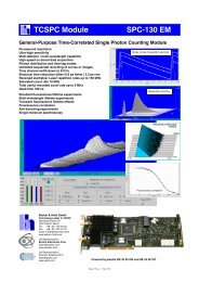
100<br />
QE (%)<br />
10<br />
1<br />
Gen 3 - FL (HVS, -63)<br />
Gen 3 - FL (EVS, -A3)<br />
Gen 3 - FL (VIH, -73)<br />
Gen 3 - FL (BGT, -C3)<br />
InGaAs (NIR, -93)<br />
Time-Resolved<br />
0.1<br />
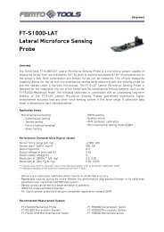
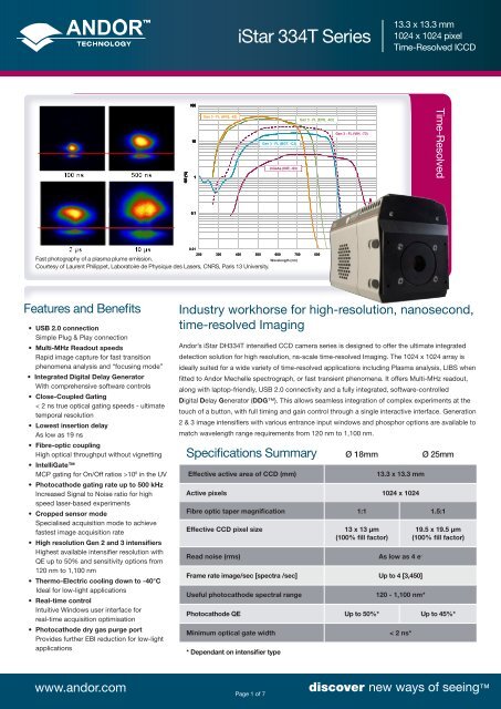
Fast photography of a plasma plume emission.<br />
Courtesy of Laurent Philippet, Laboratoire de Physique des Lasers, CNRS, Paris 13 University.<br />
0.01<br />
200 300 400 500 600 700 800 900 1000 1100<br />
Wavelength (nm)<br />
Features and Benefits<br />
• USB 2.0 connection<br />
Simple Plug & Play connection<br />
• Multi-MHz Readout speeds<br />
Rapid image capture for fast transition<br />
phenomena analysis and “focusing mode”<br />
• Integrated Digital Delay Generator<br />
With comprehensive software controls<br />
• Close-Coupled Gating<br />
< 2 ns true optical gating speeds - ultimate<br />
temporal resolution<br />
• Lowest insertion delay<br />
As low as 19 ns<br />
• Fibre-optic coupling<br />
High optical throughput without vignetting<br />
• IntelliGate<br />
MCP gating for On/Off ratios >10 8 in the UV<br />
• Photocathode gating rate up to 500 kHz<br />
Increased Signal to Noise ratio for high<br />
speed laser-based experiments<br />
• Cropped sensor mode<br />
Specialised acquisition mode to achieve<br />
fastest image acquisition rate<br />
• High resolution Gen 2 and 3 intensifiers<br />
Highest available intensifier resolution with<br />
QE up to 50% and sensitivity options from<br />
120 nm to 1,100 nm<br />
• Thermo-Electric cooling down to -40°C<br />
Ideal for low-light applications<br />
• Real-time control<br />
Intuitive Windows user interface for<br />
real-time acquisition optimisation<br />
• Photocathode dry gas purge port<br />
Provides further EBI reduction for low-light<br />
applications<br />
Industry workhorse for high-resolution, nanosecond,<br />
time-resolved Imaging<br />
Andor’s <strong>iStar</strong> DH<strong>334T</strong> intensified CCD camera series is designed to offer the ultimate integrated<br />
detection solution for high resolution, ns-scale time-resolved Imaging. The 1024 x 1024 array is<br />
ideally suited for a wide variety of time-resolved applications including Plasma analysis, LIBS when<br />
fitted to Andor Mechelle spectrograph, or fast transient phenomena. It offers Multi-MHz readout,<br />
along with laptop-friendly, USB 2.0 connectivity and a fully integrated, software-controlled<br />
Digital Delay Generator (DDG). This allows seamless integration of complex experiments at the<br />
touch of a button, with full timing and gain control through a single interactive interface. Generation<br />
2 & 3 image intensifiers with various entrance input windows and phosphor options are available to<br />
match wavelength range requirements from 120 nm to 1,100 nm.<br />
Specifications Summary Ø 18mm Ø 25mm<br />
Effective active area of CCD (mm)<br />
13.3 x 13.3 mm<br />
Active pixels 1024 x 1024<br />
Fibre optic taper magnification 1:1 1.5:1<br />
Effective CCD pixel size 13 x 13 µm<br />
(100% fill factor)<br />
Read noise (rms) As low as 4 e -<br />
Frame rate image/sec [spectra /sec] Up to 4 [3,450]<br />
Useful photocathode spectral range<br />
120 - 1,100 nm*<br />
19.5 x 19.5 µm<br />
(100% fill factor)<br />
Photocathode QE Up to 50%* Up to 45%*<br />
Minimum optical gate width<br />
* Dependant on intensifier type<br />
< 2 ns*<br />
www.andor.com<br />
Page 1 of 7<br />
discover new ways of seeing
<strong>iStar</strong> <strong>334T</strong> <strong>Series</strong><br />
13.3 x 13.3 mm<br />
1024 x 1024 pixel<br />
Time-Resolved ICCD<br />
Specifications - Gen 2 Image Intensifiers •1<br />
Photocathode model 18*-03 18*-04 18*-05 † 18H-13 18H-83 18*-E3 25*-03<br />
Useful aperture Ø 18 mm Ø 25 mm<br />
Input window Quartz Quartz MgF 2<br />
Quartz Quartz Quartz Quartz<br />
Photocathode type W-AGT W-AGT W-AGT WR UW WE-AGT W-AGT<br />
Peak QE @ room temperature •2 18 18 15 13.5 25 22 16<br />
Wavelength range 180 - 850 nm 180 - 850 nm 120 - 850 nm 180 - 920 nm 180 - 850 nm 180 - 850 nm 180 - 850 nm<br />
Image intensifier resolution limit •3 25 µm 30 µm 25 µm 25 µm 25 µm 25 µm 35µm<br />
Phosphor type [decay time to 10%] P43 [2 ms] P46 [200 ns] P43 [2 ms] P43 [2 ms] P43 [2 ms] P43 [2 ms] P43 [2 ms]<br />
Minimum optical gate width (ns) •4, 5<br />
U (Ultrafast)<br />
F (Fast)<br />
H (High QE)<br />
< 2<br />
< 5<br />
-<br />
< 2<br />
< 5<br />
-<br />
< 5<br />
< 10<br />
-<br />
-<br />
-<br />
< 50<br />
-<br />
-<br />
< 100<br />
< 2<br />
< 5<br />
-<br />
< 3<br />
< 7<br />
-<br />
Maximum relative gain •6 > 1000 > 500 > 1000 > 850 > 500 > 1000 > 1000<br />
Maximum photocathode repetition rate<br />
(with Intelligate OFF)<br />
Maximum photocathode repetition rate<br />
(with Intelligate ON)<br />
Equivalent Background Illuminance (EBI)<br />
500 kHz (continuous)<br />
5 kHz (continuous)<br />
< 0.2 e - /pix/sec<br />
* Substitute with appropriate gate width option, e.g. 18F-03 (please refer to page 5 for detailed ordering information)<br />
†<br />
Available with VUV-compatible spectrograph interface<br />
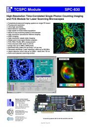
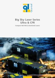
Quantum Efficiency Curves for Gen 2 Image Intensifiers •2<br />
30<br />
Gen2 (UW, H-83)<br />
20<br />
Gen 2 (WE-AGT, -E3)<br />
Gen 2 (W-AGT, -03)<br />
QE (%)<br />
10<br />
Gen 2 (WR, H-13)<br />
0<br />
200 300 400 500 600 700 800 900<br />
Wavelength (nm)<br />
www.andor.com<br />
Page 2 of 7<br />
discover new ways of seeing
<strong>iStar</strong> <strong>334T</strong> <strong>Series</strong><br />
13.3 x 13.3 mm<br />
1024 x 1024 pixel<br />
Time-Resolved ICCD<br />
Specifications - Gen 3 Image Intensifiers •1<br />
Photocathode model 18*-63 18*-73 18*-93 18*-A3 18*-C3<br />
Useful aperture<br />
Ø 18 mm<br />
Input window Glass Glass Glass Glass<br />
MgF 2<br />
+ F/O +<br />
Lumogen<br />
Photocathode type HVS VIH NIR EVS BGT<br />
Peak QE @ room temperature •2 > 47.5 > 25.5 > 4 > 40 > 17<br />
Wavelength range 280 - 760 nm 280 - 910 nm 380 - 1090 nm 280 - 810 nm < 200 - 910 nm<br />
Image intensifier resolution limit •3 30 µm 30 µm 30 µm 30 µm 40 µm<br />
Phosphor type [decay time to 10%]<br />
P43 [2 ms]<br />
Minimum optical gate width (ns) •5<br />
U (Ultrafast)<br />
F (Fast)<br />
< 2<br />
< 5<br />
Maximum relative gain •6 > 200<br />
Maximum photocathode repetition rate<br />
(with Intelligate OFF)<br />
Maximum photocathode repetition rate<br />
(with Intelligate ON)<br />
500 kHz (continuous)<br />
5 kHz (continuous)<br />
Equivalent Background Illuminance (EBI) < 0.1 e - /pix/sec < 0.3 e - /pix/sec < 2 e - /pix/sec < 0.2 e - /pix/sec < 0.3 e - /pix/sec<br />
* Substitute with appropriate gate width option, e.g. 18U-63 (please refer to page 5 for detailed ordering information)<br />
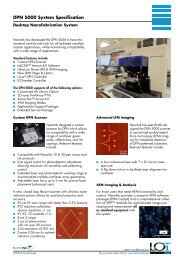
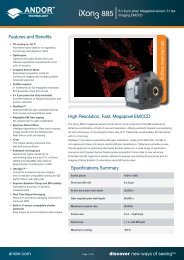
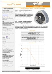
Quantum Efficiency Curves for Gen 3 Image Intensifiers<br />
100<br />
•2, •7<br />
Gen 3 - FL (HVS, -63)<br />
Gen 3 - FL (EVS, -A3)<br />
Gen 3 - FL (VIH, -73)<br />
10<br />
Gen 3 - FL (BGT, -C3)<br />
InGaAs (NIR, -93)<br />
QE (%)<br />
1<br />
0.1<br />
0.01<br />
200 300 400 500 600 700 800 900 1000 1100<br />
Wavelength (nm)<br />
www.andor.com<br />
Page 3 of 7<br />
discover new ways of seeing
<strong>iStar</strong> <strong>334T</strong> <strong>Series</strong><br />
13.3 x 13.3 mm<br />
1024 x 1024 pixel<br />
Time-Resolved ICCD<br />
CCD Specifications •1 Total CCD matrix size 1024 x 1024<br />
Fibre optic taper magnification<br />
Effective CCD pixel size<br />
Ø 18 mm<br />
1:1<br />
Ø 18 mm<br />
13 x 13 µm<br />
Ø 25 mm<br />
1.5:1<br />
Ø 25 mm<br />
19.5 x 19.5 µm<br />
Effective active area<br />
13.3 x 13.3 mm<br />
Image pixel well depth 100,000 e -<br />
Register well depth 150,000 e -<br />
Read noise e - •8<br />
50 kHz<br />
1 MHz<br />
3 MHz<br />
5 MHz<br />
Typical<br />
Maximum<br />
5<br />
7<br />
8<br />
12<br />
14<br />
18<br />
20<br />
50<br />
Vertical shift speeds<br />
6.5 to 12.9 µs (software selectable)<br />
Maximum frame and spectral rates<br />
Frame<br />
4.2 full fps<br />
7.3 fps (2x2 binning)<br />
FVB<br />
145 sps<br />
Crop Mode<br />
(10 rows)<br />
333 fps<br />
3,450 sps<br />
Fast Kinetics<br />
(4 rows)<br />
29,850 Hz<br />
Sensitivity<br />
1 to 5 e - /count (software selectable)<br />
Linearity •9 Better than 99%<br />
Minimum temperature air cooled [dark current, e - /pixel/sec]<br />
Coolant chiller, coolant @ 10 o C, 0.75 l/min [dark current, e - /pixel/sec]<br />
-30°C [0.2]<br />
-40°C [0.1]<br />
Internal Digital Delay Generator (DDG) Key Functions<br />
Gate pulse delay & width<br />
• Adjustable from 0 ns to 10 s in 10 ps steps<br />
• Software controlled, pre-programmed or real-time<br />
Trigger Outputs<br />
Output A, B and C<br />
Fire<br />
Arm monitor<br />
Gate & output A, B and C jitter<br />
• 3x output, +5V CMOS level with 50 Ω source impedance; can drive 5V into a non-terminating load or 2.5V into 50 Ω<br />
load; output synchronised triggers for auxiliary equipment, e.g. lasers, flash lamps, National Instrument hardware<br />
• Individual delays control from 0 ns to 10 s in 10 ps steps<br />
• Configurable Polarity<br />
• Software controlled, pre-programmed or real-time<br />
• 5V CMOS level reference signal for beginning and end of individual CCD exposure<br />
• 5V CMOS level reference signal to indicate when system is ready to accept external triggers. Signal goes high when<br />
system is ready to accept external triggers (after a readout has finished) and goes low when the exposure is finished<br />
• 35 ps rms (relative to external trigger signal)<br />
Trigger Inputs<br />
External trigger<br />
Direct gate<br />
• Trigger input for CCD and Digital Delay Generator<br />
• Up to 500 kHz for Integrate-On-Chip mode<br />
• Software-configurable Polarity, Termination and Trigger Threshold<br />
• Fast external software option for most rapid camera response to external trigger (CCD keep clean interruption) – no<br />
need for pre-trigger pulse<br />
• TTL input for exact external control of photocathode width and timing with smallest<br />
insertion delay.<br />
Additional Controls<br />
Gate monitoring<br />
Insertion delay<br />
• AC coupling from photocathode to monitor exact photocathode on/off switching and timings<br />
< 19 ns in direct gate operation<br />
Have you found what you are looking for?<br />
Need faster response phosphor for Fast Kinetics? P46 phosphor is available as an option for all models.<br />
Need a customised version? Please contact us to discuss our Customer Special Request (CSR) options.<br />
www.andor.com<br />
Page 4 of 7<br />
discover new ways of seeing
<strong>iStar</strong> <strong>334T</strong> <strong>Series</strong><br />
13.3 x 13.3 mm<br />
1024 x 1024 pixel<br />
Time-Resolved ICCD<br />
Creating The Optimum<br />
Product for You<br />
How to customise the New <strong>iStar</strong> DH<strong>334T</strong>:<br />
DH<strong>334T</strong>example<br />
shown<br />
25<br />
-<br />
F - 03<br />
Step 1.<br />
Select the diameter of intensifier<br />
required.<br />
Step 2.<br />
Select the minimum gating speed<br />
option that best suits your needs. For<br />
the available combinations please<br />
refer to the image intensifer tables on<br />
pages 2 and 3.<br />
Step 3.<br />
Select the image intensifier type that<br />
best suits your needs.<br />
Step 1.<br />
Choose intensifier diameter<br />
18: Ø 18 mm<br />
25: Ø 25 mm<br />
Step 3.<br />
Choose image intensifier option<br />
Step 2.<br />
(Gen 2):<br />
03: W-AGT photocathode, P43 phosphor<br />
04: W-AGT photocathode, P46 phosphor<br />
05: W-AGT photocathode, MgF 2<br />
window, P43 phosphor<br />
13: WR photocathode, P43 phosphor<br />
83: UW photocathode, P43 phosphor<br />
E3: WE-AGT photocathode, P43 phosphor<br />
Choose minimum gating speed<br />
H: High QE, slow gating<br />
F: Fast gating<br />
U: Ultra fast gating<br />
Choose image intensifier option<br />
(Gen 3):<br />
63: HVS photocathode, P43 phosphor<br />
73: VIH photocathode, P43 phosphor<br />
93: NIR photocathode, P43 phosphor<br />
A3: EVS photocathode, P43 phosphor<br />
C3: BGT photocathode, P43 phosphor<br />
Step 2.<br />
Step 4.<br />
Please indicate which software you<br />
require.<br />
Step 5.<br />
For compatibility, please indicate<br />
which accessories are required.<br />
Step 4.<br />
The New <strong>iStar</strong> ICCD also requires at least one of the following software options:<br />
Solis for Time-Resolved A 32-bit application compatible with 32 and 64-bit Windows (XP,<br />
Vista and 7) offering rich functionality for data acquisition and processing. AndorBasic provides<br />
macro language control of data acquisition, processing, display and export.<br />
Andor SDK A software development kit that allows you to control the Andor range of cameras<br />
from your own application. Available as 32 and 64-bit libraries for Windows (XP, Vista and 7)<br />
and Linux. Compatible with C/C++, C#, Delphi, VB6, VB.NET, LabVIEW and Matlab.<br />
Step 5.<br />
The following accessories are available:<br />
LM-C C-mount lens adaptor<br />
LM-NIKON-F F-mount lens adaptor<br />
ACC-XW-CHIL-160 Oasis 160 Ultra compact chiller unit<br />
ACC-6MM-TUBING-2xxxxM 6 mm tubing option for ACC-XW-CHIL-160<br />
In addition to the accessories listed the following special options are also available:<br />
90° USB connection<br />
UV or visible lenses or adapter extension tubes<br />
Please contact your local Sales representative for details of how to order any of these items.<br />
Spectrograph Compatibility<br />
The <strong>iStar</strong> series is fully compatible with Andor’s Shamrock spectrograph (163 - 750 mm focal<br />
lengths) family. Spectrograph mounting flanges and software control are available for a wide<br />
variety of 3rd party spectrographs including, McPherson, JY/Horiba, PI/Acton, Chromex/Bruker,<br />
Oriel/Newport, Photon Design, Dongwoo, Bentham, Solar TII and others.<br />
No specific flange is required for the Andor Mechelle 5000 as this combination comes as a<br />
fully integrated system.<br />
www.andor.com<br />
Page 5 of 7<br />
discover new ways of seeing
<strong>iStar</strong> <strong>334T</strong> <strong>Series</strong><br />
13.3 x 13.3 mm<br />
1024 x 1024 pixel<br />
Time-Resolved ICCD<br />
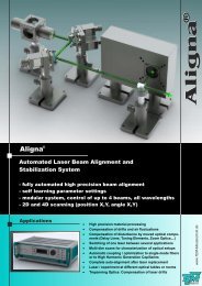
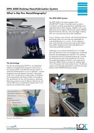
Product Drawings<br />
Dimensions in mm [inches]<br />
110.7 [4.36]<br />
Gate monitor skt<br />
(behind grommet)<br />
Air in top grill<br />
Air out, side grills<br />
52.0 [2.05]<br />
O-ring 53.7 I.D [2.11]<br />
2.0 [0.08] wide, (BS034)<br />
•<br />
90.0 [3.54]<br />
47.0 [1.85]<br />
Dry gas purge<br />
for intensifier input<br />
window, push fit<br />
for 6.0 mm [0.24] O.D.<br />
plastic hose<br />
(vent opposite side)<br />
137.2 [5.40]<br />
33.5 [1.32]<br />
10.0 [0.39]<br />
231.0 [9.09]<br />
Access points for allen key<br />
to 4 off mounting screws<br />
(90 x 52 grid on faceplate)<br />
Water connectors<br />
quick release<br />
to suit 1/4" i.d<br />
soft PVC hose<br />
23.3 [0.92]<br />
Air in<br />
(out opposite side)<br />
Weight: 4.2 kg [9 lb 4 oz]<br />
•= position of pixel 1,1<br />
50.8 [2.00]<br />
Connecting to the <strong>iStar</strong><br />
Camera Control<br />
Connector type: USB 2.0<br />
Logic Input / Output<br />
Connector type: SMA, provided with SMA - BNC cable<br />
5x outputs: FIRE pulse, Output A, B, C from DDG and ARM<br />
2x inputs: Camera trigger from 3 rd party source & direct gate for<br />
complete, direct external control of intensifier gating<br />
I 2 C connector<br />
Compatible with Fischer SC102A054-130, pin-outs as follow:<br />
1 = Shutter (5V CMOS level with 50 Ω impedance), 2 = I 2 C Clock<br />
(5V), 3 = I 2 C Data (5V), 4 = +5 Vdc, 5 = Ground<br />
Gate Monitor<br />
1x output: AC coupling to photocathode<br />
47.0 [1.85]<br />
58.9 [2.32]<br />
Mounting hole locations<br />
3 off 1/4-20 UNC<br />
mounting pillar holes<br />
External trigger<br />
Power<br />
socket<br />
On/Off<br />
switch<br />
Grounding point<br />
USB 2.0<br />
DDG outputs<br />
A B C<br />
Rear connector panel<br />
Fire<br />
Arm<br />
Direct gate<br />
Quick lock<br />
water connectors<br />
2<br />
I C<br />
Applications Guide Gen 2<br />
Gen 2 UV Enhanced<br />
(-05, -83, -E3)<br />
Gen 3*<br />
InGaAs<br />
Plasma Studies<br />
Laser Induced Fluorescence (LIF, PLIF)<br />
Time Resolved Luminescence Imaging & Spectroscopy<br />
Laser Induced Breakdown Spectroscopy (LIBS)<br />
Transient Absorption Imaging<br />
Time Resolved Photoluminescence Imaging<br />
Particle Image Velocimetry (PIV)<br />
* Gen 3 typically do not exhibit any UV response - Andor -C3 is constructed with an additional input phosphor interface to provide this UV response.<br />
= Suitable<br />
= Optimum<br />
www.andor.com<br />
Page 6 of 7<br />
discover new ways of seeing
<strong>iStar</strong> <strong>334T</strong> <strong>Series</strong><br />
13.3 x 13.3 mm<br />
1024 x 1024 pixel<br />
Time-Resolved ICCD<br />
Order Today<br />
Need more information? At Andor we are committed to finding<br />
the correct solution for you. With a dedicated team of technical<br />
advisors, we are able to offer you one-to-one guidance and<br />
technical support on all Andor products. For a full listing of our<br />
local sales offices, please see: www.andor.com/contact<br />
Our regional headquarters are:<br />
Europe<br />
Japan<br />
Belfast, Northern Ireland<br />
Tokyo<br />
Phone +44 (28) 9023 7126 Phone +81 (3) 3518 6488<br />
Fax +44 (28) 9031 0792 Fax +81 (3) 3518 6489<br />
North America<br />
China<br />
Connecticut, USA<br />
Beijing<br />
Phone +1 (860) 290 9211 Phone +86 (10) 5129 4977<br />
Fax +1 (860) 290 9566 Fax +86 (10) 6445 5401<br />
Items shipped with your camera<br />
Power Brick, 12V, 120W single line<br />
2x 2m BNC to SMA cable<br />
1x Gate Monitor cable<br />
3 Metre USB cable A to B type, shielded (1off)<br />
1x Quick launch guide<br />
1x CD containing Andor user guides<br />
1x Individual system performance booklet<br />
Regulatory Compliance<br />
Compliant with the requirements of the<br />
EU EMC and LV Directives through testing to<br />
EN 61326-1 and EN 61010-1.<br />
External power supply PSE-approved<br />
Footnotes: Specifications are subject to change without notice<br />
1. Figures are typical unless otherwise stated.<br />
2. Typical photocathode Quantum Efficiency and standard quartz input window transmission as measured by<br />
the tube manufacturer. MgF 2<br />
window allows extended operation down to 120 nm.<br />
3. Typical resolution of the image intensifier tube only, not the overall resolution of the system. As a rough<br />
guide, the smallest resolvable FWHM feature will be approximately 2x the CCD pixel size. This is a very<br />
important consideration for optical resolution calculations in spectrograph-based systems.<br />
4. Gen 2 High QE (H) option – Photocathode QE is inherently linked to the gating speed of the intensifier.<br />
High QE option (H) offers higher peak QE than Ultrafast (U) or Fast (F) intensifiers, while exhibiting minimum<br />
gating speed one order of magnitude slower.<br />
5. Actual measured minimum optical gating of the photocathode, reflecting not only the electrical pulse width<br />
applied to the photocathode but also its inherent irising time.<br />
6. Gain is software-selectable through a 12-bit DAC and varies exponentially with DAC setting. Value refers<br />
to the ratio of max to min intensifier gain as measured for individual cameras. Actual optical gain<br />
(counts/photoe - ) for a DAC setting is accessed by the multiplication of the relative gain (at that DAC value)<br />
by the minimum system gain (at DAC = 0, CCD e - /photoe - ) and divided by the sensitivity (CCD e - /count) at<br />
a given CCD PAG. Sensitivities are individually measured and reported for each system.<br />
7. Combination of -73 GaAsP photocathode with a lumogen-coated fibre-optic plate and protective<br />
MgF 2<br />
window. The latter additional optical interfaces are the reason for the lowered QE in the visible<br />
NIR region, for the -C3 model.<br />
8. Measured for the entire system. Combination of CCD readout noise and A/D noise - measurement<br />
is for single pixel readout with -30°C CCD cooling and at minimum exposure time under dark conditions.<br />
Values quoted are measured with highest available PAG setting.<br />
9. Linearity is measured from a plot of counts vs exposure time under constant photon flux up to the<br />
saturation point of the system.<br />
Minimum Computer Requirements:<br />
• 3.0 GHz single core or 2.4 GHz multi core processor<br />
• 2 GB RAM<br />
• 100 MB free hard disc to install software<br />
(at least 1 GB recommended for data spooling)<br />
• USB 2.0 High Speed Host Controller<br />
capable of sustained rate of 40MB/s<br />
• Windows (XP, Vista and 7) or Linux<br />
www.andor.com<br />
Operating & Storage Conditions<br />
Operating Temperature 0°C to 40°C ambient<br />
Relative Humidity < 70% (non-condensing)<br />
Storage Temperature -20°C to 55°C<br />
Power Requirements<br />
110 - 240 VAC, 50 - 60 Hz<br />
Page 7 of 7<br />
Windows is a registered trademark of Microsoft Corporation.<br />
Labview is a registered trademark of National Instruments.<br />
Matlab is a registered trademark of The MathWorks Inc.<br />
T<strong>iStar</strong><strong>334T</strong>SS 0611 R3<br />
discover new ways of seeing