HT 2016 - Digital jordmodstandsmĺling. - Elma Instruments
HT 2016 - Digital jordmodstandsmĺling. - Elma Instruments
HT 2016 - Digital jordmodstandsmĺling. - Elma Instruments

You also want an ePaper? Increase the reach of your titles
YUMPU automatically turns print PDFs into web optimized ePapers that Google loves.
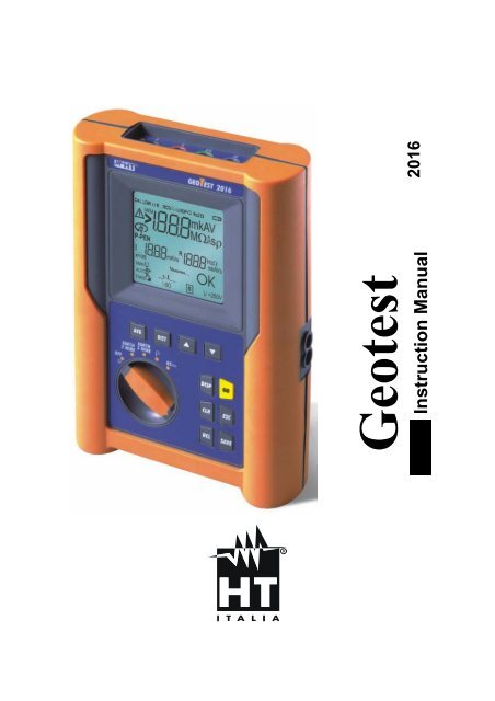
Instruction Manual<br />
<strong>2016</strong>
Geotest <strong>2016</strong><br />
Version EN 1.01 of 19/10/2000<br />
1. PRECAUTIONS AND SAFETY MEASURES..............................................................3<br />
1.1. PRELIMINARY INSTRUCTIONS ..................................................................................... 3<br />
1.2. DURING USE ................................................................................................................... 4<br />
1.3. AFTER USE...................................................................................................................... 4<br />
2. GENERAL DESCRIPTION..........................................................................................5<br />
2.1. INSTRUMENT DESCRIPTION......................................................................................... 6<br />
3. PREPARING THE INSTRUMENT...............................................................................8<br />
3.1. INITIAL CHECK ................................................................................................................ 8<br />
3.2. POWER SUPPLY ............................................................................................................. 8<br />
3.3. CALIBRATION.................................................................................................................. 8<br />
3.4. STORAGE ........................................................................................................................ 8<br />
4. SWITCH FUNCTIONS ................................................................................................9<br />
4.1. EARTH 2 WIRES..............................................................................................................9<br />
4.1.1. TWO WIRES EARTH RESISTANCE MEASUREMENT ON THE SOCKET ................................... 12<br />
4.2. EARTH 3 WIRES............................................................................................................ 13<br />
4.3. "ρ" MODE (Resistivity of the Earth) ................................................................................ 16<br />
4.4. ANOMALOUS SITUATIONS WHICH CAN OCCUR DURING TESTS........................... 21<br />
5. HOW TO SAVE, RECALL AND CANCEL DATA.......................................................24<br />
5.1. TO SAVE: KEY "SAVE"................................................................................................. 24<br />
5.2. TO RECALL: KEY "RCL"................................................................................................ 25<br />
5.3. TO CANCEL: KEY "CLR" ............................................................................................... 26<br />
6. RESET AND DEFAULT PARAMETERS...................................................................28<br />
6.1. HARD RESET................................................................................................................. 28<br />
6.2. DEFAULT PARAMETERS.............................................................................................. 28<br />
6.2.1. DEFAULT PARAMETERS................................................................................................ 28<br />
7. CONNECTING THE INSTRUMENT TO A PC ..........................................................29<br />
8. MAINTENANCE ........................................................................................................30<br />
8.1. GENERAL....................................................................................................................... 30<br />
8.2. BATTERY REPLACEMENT ........................................................................................... 30<br />
8.3. CLEANING ..................................................................................................................... 30<br />
9. TECHNICAL SPECIFICATIONS ...............................................................................31<br />
9.1. TECHNICAL FEATURES ............................................................................................... 31<br />
9.1.1. SAFETY STANDARDS .................................................................................................... 32<br />
9.1.2. GENERAL FEATURES.................................................................................................... 32<br />
9.2. OPERATING CONDITIONS ........................................................................................... 33<br />
9.2.1. ENVIRONMENTAL CONDITIONS ...................................................................................... 33<br />
9.2.2. EMC .......................................................................................................................... 33<br />
9.3. ACCESSORIES.............................................................................................................. 33<br />
9.3.1. STANDARD AND OPTIONAL ACCESSORIES...................................................................... 33<br />
10. AFTER-SALE SERVICE ...........................................................................................34<br />
10.1. WARRANTY ................................................................................................................... 34<br />
10.2. SERVICE ........................................................................................................................ 34<br />
11. PRACTICAL CARDS TO CARRY OUT ELECTRICAL TESTS .................................35<br />
11.1. EARTH RESISTANCE MEASUREMENT....................................................................... 35<br />
11.2. EARTH RESISTIVITY MEASUREMENT........................................................................ 38<br />
EN - 2
1. PRECAUTIONS AND SAFETY MEASURES<br />
Geotest <strong>2016</strong><br />
Version EN 1.01 of 19/10/2000<br />
This instrument complies with EN61557-1, EN61557-5 and EN 61010-1 standards.<br />
ν WARNING:<br />
For your safety as well as that of the apparatus you are<br />
recommended to follow the procedures described in this<br />
instruction manual and carefully read all the notes preceded by<br />
the symbol .<br />
Before and during measurements please keep very diligently to the instructions below:<br />
Do not measure in wet or dusty places;<br />
Do not measure in presence of gas, explosive materials or combustibles;<br />
Do not touch the circuit under test if no measurement is being taken;<br />
Do not touch exposed metal parts, unused terminals, circuits and so on;<br />
Do not use the instrument if it seems malfunctioning (i.e. if you notice deformations,<br />
breaks, leakage of substances, absence of messages on the display and so on);<br />
Be particularly careful when measuring voltages higher than 25V in special places<br />
(such as building sites, swimming pools and so on) and higher than 50V in ordinary<br />
places to avoid the risk of electrical shocks.<br />
The following symbols are used in this manual:<br />
Warning: Should you fail to keep to the prescribed instructions you could<br />
damage the instrument and/or its components or endanger your safety.<br />
Switch<br />
1.1. PRELIMINARY INSTRUCTIONS<br />
This instrument has been designed to be used in places with pollution 2.<br />
It can be used for tests on installations of excess voltage category III max 250V (phase to<br />
earth).<br />
Always keep to the usual safety standards aimed at:<br />
- protecting you against dangerous currents;<br />
- protecting the instrument against incorrect operations.<br />
Only the accessories supplied with the instrument guarantee compliance with the<br />
safety standards. Accordingly, they must be in good conditions and, if necessary, they<br />
must be replaced with identical models.<br />
Do not take measurements on circuits exceeding the specified current and voltage<br />
limits.<br />
Do not take measurements in conditions exceeding the limits stated at paragraphs<br />
9.2.1 and 9.2.2.<br />
Make sure that the batteries are well inserted.<br />
EN - 3
Geotest <strong>2016</strong><br />
Version EN 1.01 of 19/10/2000<br />
Before connecting the crocodiles to the circuit under test, make sure that the switch is<br />
well positioned.<br />
Make sure that display and switch show the same function.<br />
1.2. DURING USE<br />
Please read carefully:<br />
ν WARNING:<br />
Should you fail to keep to the prescribed instructions you could<br />
damage the instrument and/or its components or endanger your<br />
safety.<br />
Before positioning the switch disconnect the crocodiles from the circuit under test.<br />
When the instrument is connected to the circuit under test do not touch any unused<br />
terminal.<br />
Do not take resistance measurements in presence of external voltages; even if the<br />
instrument is protected, an excessive voltage could cause malfunctioning.<br />
ν WARNING: If during use the symbol appears, suspend the test and<br />
replace the batteries (see paragraph 8.2). The instrument is<br />
able to keep memorised the data previously saved for<br />
approx 10 minutes.<br />
1.3. AFTER USE<br />
After use, position the switch on OFF.<br />
If you expect not to use the instrument for a long time remove the batteries.<br />
EN - 4
2. GENERAL DESCRIPTION<br />
Geotest <strong>2016</strong><br />
Version EN 1.01 of 19/10/2000<br />
The instrument you have just purchased will grant you accurate and reliable measurements<br />
provided that it is used according to these manual’s instructions<br />
Geotest <strong>2016</strong> is able to measure:<br />
EARTH 2 WIRES: 2 wires earth resistance<br />
EARTH 3 WIRES: 3 wires earth resistance<br />
ρ: 4 wire earth resistivity<br />
EN - 5
2.1. INSTRUMENT DESCRIPTION<br />
Geotest <strong>2016</strong><br />
Version EN 1.01 of 19/10/2000<br />
DIST<br />
AVG<br />
σ<br />
σ<br />
Rotary switch:<br />
it permits to select<br />
the desired function<br />
OFF<br />
DISP<br />
GO<br />
CLR<br />
ESC<br />
RCL<br />
SAVE<br />
picture 1: front panel<br />
EN - 6
AVG<br />
<br />
Geotest <strong>2016</strong><br />
Version EN 1.01 of 19/10/2000<br />
to display the medium value of the earth resistivity, calculated on the<br />
basis of all the valid measurements taken.<br />
DIST to select the distance D between the earth rods (ρ resistivity test).<br />
σ<br />
<br />
to increase the value of the parameter D or to run over the memorised<br />
test results.<br />
τ<br />
<br />
to decrease the value of the parameter D or to run over the memorised<br />
test results.<br />
GO to start a measurement.<br />
ESC<br />
<br />
to leave the selected function or mode.<br />
SAVE to save the test results.<br />
RCL<br />
<br />
to recall the memorised test results.<br />
DISP<br />
<br />
to display the tests effected and memorised.<br />
CLR<br />
<br />
to cancel the the medium value, the number of the tests inside the<br />
medium value and memorised test results.<br />
EN - 7
3. PREPARING THE INSTRUMENT<br />
Geotest <strong>2016</strong><br />
Version EN 1.01 of 19/10/2000<br />
3.1. INITIAL CHECK<br />
This instrument has been checked before shipment from an electrical and mechanical<br />
point of view.<br />
All possible precautions have been taken in order to deliver it in perfect conditions.<br />
Notwithstanding, on receipt of the instrument we suggest you to check it summarily to<br />
make sure that no damage has occurred in transit. Should you find anomalies please<br />
contact the carrier immediately.<br />
Furthermore, please make sure that the parcel contains all the accessories and parts listed<br />
at paragraph 9.3.1. In case of discrepancies please contact your dealer.<br />
Should it be necessary to return the instrument to the supplier please keep to the<br />
instructions given at paragraph 10.<br />
3.2. POWER SUPPLY<br />
The instrument is powered by 6 batteries 1.5V – LR6 – AA – AM3 – MN 1500 not included<br />
in the package. For the battery autonomy see paragraph 0.<br />
For a correct inserting of the batteries see paragraph 8.2.<br />
When the batteries are low the symbol<br />
paragraph 8.2.<br />
appears. For a correct replacement see<br />
3.3. CALIBRATION<br />
The instrument complies with the standards mentioned in this manual. Its performances<br />
are guaranteed for one year from the purchase date.<br />
3.4. STORAGE<br />
To guarantee accurate measurements, after a long storage period in severe environmental<br />
conditions wait until the instrument resumes its normal conditions (see environmental<br />
conditions listed at paragraph 9.2.1).<br />
EN - 8
4. SWITCH FUNCTIONS<br />
Geotest <strong>2016</strong><br />
Version EN 1.01 of 19/10/2000<br />
4.1. EARTH 2 WIRES<br />
Whenever it’s not possible to drive rods into the ground to take a 3-wire measurement (i.e.<br />
in historical towns), in case of TT installations it’s possible to use the simplified 2-wire<br />
method (picture 2) which gives an excess value (therefore safer).<br />
To carry out the test a suitable auxiliary rod is necessary; a rod is “suitable” when its<br />
earth resistance is negligible and it is independent of the earth equipment under test.<br />
In picture 2 a water pipe has been used as auxiliary rod. However, any metal body driven<br />
into the ground can be used, provided that the above said requirements are met.<br />
Although this test is not provided for by CEI 64.8 at present, it gives a value which many 3-<br />
wires comparison tests proved to be revealing for earth resistance.<br />
E S ES H<br />
picture 2: 2 wires earth resistance measurement<br />
Measuring procedure:<br />
Insert the 4 connectors (black, red, blue and green) of the measure cables into the<br />
corresponding input terminals of the instrument (E, S, H, ES).<br />
Connect the crocodiles as shown in picture 2.<br />
<br />
Position the switch on EARTH 2 WIRES.<br />
Display outlook:<br />
Secondary display on the lefthand<br />
side:<br />
In this stage it displays the<br />
eventual interfering voltage<br />
present on the circuit<br />
---<br />
0 V -<br />
- -<br />
Main display<br />
Secondary display on the<br />
right-hand side<br />
EN - 9
GO<br />
Geotest <strong>2016</strong><br />
Version EN 1.01 of 19/10/2000<br />
Press GO to take the measurement and read the result on the display. At the<br />
end of the test a screen similar to the following will be displayed.<br />
NOTE!<br />
If you keep pressing GO, the instrument takes more measurements<br />
consecutively. When a new value is acquired, the symbol Ω blinks on the main<br />
display, the instrument emits a short sound and the counter shown on the<br />
secondary display on the left-hand side is updated. This counter indicates the<br />
quantity of measurements calculated on the basis of the medium resistance<br />
value.<br />
No. of earth resistance<br />
measurements<br />
included in the<br />
calculation of the<br />
medium resistance<br />
0.96 Ω<br />
2<br />
0.93 Ω<br />
Value of the<br />
resistance<br />
Medium value of the resistance calculated<br />
as:<br />
(Val1+Val2+…+Valn)/(No. measurements)<br />
ν WARNING:<br />
When the message “Measuring” appears on the display, the<br />
instrument is measuring. Do not disconnect the crocodiles<br />
during the measurement.<br />
Ex.:<br />
if the operator takes three measurements consecutively, the instrument will<br />
display:<br />
- 1 st measurement:<br />
main display = measured resistance value (Ex: 0.90Ω)<br />
secondary display on the left-hand side = 001 (no. of measurements = 1<br />
means that 1 earth measurement has been taken)<br />
secondary display on the right-hand side = average of the measurements<br />
taken (in case just one measurement has been taken the medium value is<br />
equal to the measured value, in this case 0.90Ω)<br />
- 2 nd measurement:<br />
main display = measured resistance value (Ex: 0.96Ω)<br />
secondary display on the left-hand side = 002 (no. of measurements = 2<br />
means that 2 earth measurements have been taken consecutively)<br />
secondary display on the right-hand side = average of the measurements<br />
taken ((Val1+Val2)/no. of measurements = (0.90+0.96)/2 = 0.93Ω)<br />
- 3 rd measurement:<br />
main display = measured resistance value (Ex: 0.93Ω)<br />
EN - 10
Geotest <strong>2016</strong><br />
Version EN 1.01 of 19/10/2000<br />
secondary display on the left-hand side = 003 (no. of measurements = 3<br />
means that 3 earth measurements have been taken consecutively)<br />
secondary display on the right-hand side = average of the measurements<br />
taken ((Val1+Val2)/no. of measurements = (0.90+0.96+0.93)/3 = 0.93Ω)<br />
NOTE!<br />
The test with result over 700Ω is not inserted in the calculation of medium<br />
value.<br />
Example:<br />
1 st measurement<br />
Main display: 1,07Ω<br />
Secondary display on the left-hand side: 1<br />
Secondary display on the right-hand side: 1,07Ω<br />
2 st measurement<br />
Main display: 4,15Ω<br />
Secondary display on the left-hand side: 2<br />
Secondary display on the right-hand side: 2,61Ω<br />
3 st measurement (not inserted in the medium value)<br />
Main display: 1018Ω<br />
Secondary display on the left-hand side: 2<br />
Secondary display on the right-hand side: 2,61Ω<br />
CLR<br />
Press CLR if you want to cancel the medium value of the resistance and the no.<br />
of measurements which are included in the calculation (displayed on the<br />
secondary displays on the right-hand side and on the left-hand side<br />
respectively). A screen similar to the following will be displayed:<br />
0.96 Ω<br />
Last value of resistance<br />
measured<br />
- - -<br />
- - -<br />
SAVE<br />
The test results can be memorised by pressing SAVE (see paragraph 5.1).<br />
NOTE!<br />
The resistance measurement is taken according to a 4-wires voltmetric method.<br />
Therefore, it’s not affected by the resistance value of the cables used: it’s not<br />
necessary to calibrate the cables or their extension.<br />
EN - 11
4.1.1. Two wires earth resistance measurement on the socket<br />
EARTH 2 WIRES<br />
Geotest <strong>2016</strong><br />
Version EN 1.01 of 19/10/2000<br />
On TT installations it’s possible to take an earth measurement with a simplified method,<br />
which gives an excess value (therefore safer), using the NEUTRAL of the national Energy<br />
Board taken directly from a socket as an auxiliary rod; if also the earth connection is<br />
available, naturally the measurement can be taken on the socket directly, between<br />
NEUTRAL and EARTH.<br />
Although this test is not provided for by CEI 64.8 at present, it gives a value which many 3-<br />
wires comparison tests proved to be revealing for earth resistance.<br />
E S ES H<br />
picture 3<br />
NOTE!<br />
If you want to take the measurement using the neutral and the earth of a normal<br />
socket, you may happen to connect to the phase. In this case the display will<br />
show the voltage, the symbol (wrong inserting) and won’t take any<br />
measurement even if GO is pressed.<br />
EN - 12
4.2. EARTH 3 WIRES<br />
Geotest <strong>2016</strong><br />
Version EN 1.01 of 19/10/2000<br />
The measurement is taken according to what prescribed for CEI 64.8, IEC 781, VDE 0413,<br />
EN61557-5.<br />
CAT III<br />
440 V P-N-PE<br />
250 V<br />
H<br />
E S ES<br />
H<br />
Small earth plant:<br />
- current probe positioned a<br />
distance from the earth<br />
equipment outline corresponding<br />
to five times the diagonal of the<br />
area of the earth equipment.<br />
Big earth plant:<br />
- current probe positioned a<br />
distance from the earth<br />
equipment outline corresponding<br />
the diagonal of the area of the<br />
earth equipment.<br />
picture 4: 3 wires earth resistance measurement<br />
Measuring procedure:<br />
Insert the 4 connectors (black, red, blue and green) of the cables of KITTERR4C into<br />
the corresponding input terminals of the instrument (E, S, H, ES).<br />
Connect the crocodiles as shown in picture 3.<br />
<br />
Position the switch on EARTH 3 WIRES.<br />
Display outlook:<br />
Secondary display on the lefthand<br />
side:<br />
In this stage it displays the<br />
eventual interfering voltage<br />
present on the circuit<br />
---<br />
0 V -<br />
- -<br />
Main display<br />
Secondary display on the<br />
right-hand side<br />
GO<br />
Press GO to take the measurement and read the value on the display. At the<br />
end of the test a screen similar to the one beside will be displayed.<br />
NOTE!<br />
If you keep pressing GO, the instrument takes more measurements<br />
consecutively. When a new value is displayed, the symbol Ω blinks on the main<br />
display, the instrument emits a short sound and the counter shown on the<br />
EN - 13
Geotest <strong>2016</strong><br />
Version EN 1.01 of 19/10/2000<br />
secondary display on the left-hand side is updated. This counter indicates the<br />
quantity of measurements included in the calculation of the medium resistance<br />
value.<br />
No. of earth resistance<br />
measurements included in the<br />
calculation of the medium resistance<br />
0.96 Ω<br />
2<br />
0.93 Ω<br />
Value of the resistance<br />
measured<br />
Medium value of the resistance calculated<br />
as:<br />
(Val1+Val2+…+Valn)/(no. measurements)<br />
ν WARNING:<br />
When the message “Measuring” appears on the display, the<br />
instrument is measuring. Do not disconnect the crocodiles<br />
during the measurement.<br />
Ex.:<br />
if the operator takes three measurements consecutively, the instrument will<br />
display:<br />
- 1 st measurement:<br />
main display = measured resistance value (Ex: 0.90Ω)<br />
secondary display on the left-hand side = 001 (no. of measurements = 1<br />
means that 1 earth measurement has been taken)<br />
secondary display on the right-hand side = average of the measurements<br />
taken (in case just one measurement has been taken the medium value is<br />
equal to the measured value, in this case 0.90Ω)<br />
- 2 nd measurement:<br />
main display = measured resistance value (Ex: 0.96Ω)<br />
secondary display on the left-hand side = 002 (no. of measurements = 2<br />
means that 2 earth measurements have been taken consecutively)<br />
secondary display on the right-hand side = average of the measurements<br />
taken ((Val1+Val2)/no. of measurements = (0.90+0.96)/2 = 0.93Ω)<br />
- 3 rd measurement:<br />
main display = measured resistance value (Ex: 0.93Ω)<br />
secondary display on the left-hand side = 003 (no. of measurements = 3<br />
means that 3 earth measurements have been taken consecutively)<br />
secondary display on the right-hand side = average of the measurements<br />
taken ((Val1+Val2)/no. of measurements = (0.90+0.96+0.93)/3 = 0.93Ω)<br />
EN - 14
Geotest <strong>2016</strong><br />
Version EN 1.01 of 19/10/2000<br />
NOTE!<br />
The test with result over 700Ω is not inserted in the calculation of medium<br />
value.<br />
Example:<br />
1 st measurement<br />
Main display: 1,07Ω<br />
Secondary display on the left-hand side: 1<br />
Secondary display on the right-hand side: 1,07Ω<br />
2 st measurement<br />
Main display: 4,15Ω<br />
Secondary display on the left-hand side: 2<br />
Secondary display on the right-hand side: 2,61Ω<br />
3 st measurement (not inserted in the medium value)<br />
Main display: 1018Ω<br />
Secondary display on the left-hand side: 2<br />
Secondary display on the right-hand side: 2,61Ω<br />
CLR<br />
Press CLR if you want to cancel the medium resistance value and the no. of<br />
measurements which are included in the calculation (displayed on the<br />
secondary displays on the right-hand side and on the left-hand side<br />
respectively). A screen similar to the following will be displayed:<br />
0.96 Ω<br />
Last resistance value<br />
measured<br />
- - -<br />
- - -<br />
NOTE!<br />
The resistance measurement is taken according to a 4-wires voltmetric method.<br />
Therefore, it’s not affected by the resistance value of the cabled used: it’s not<br />
necessary to calibrate the cables or their extension.<br />
SAVE<br />
The test results can be memorised by pressing SAVE (see paragraph 5.1)<br />
EN - 15
4.3. "ρ" MODE (Resistivity of the Earth)<br />
Geotest <strong>2016</strong><br />
Version EN 1.01 of 19/10/2000<br />
The measurement is taken according to CEI 64.8, IEC 781, VDE 0413, EN61557-5.<br />
Measuring procedure:<br />
Drive the 4 earth rods into the ground at the same distance D. The distance D<br />
between the rods is usually 1 to 3 meters.<br />
The distance D between the rods determines the depth at which the earth<br />
resistivity is measured. In order to identify the distance (and therefore depth)<br />
corresponding to the lowest resistivity value, the test must be repeated several<br />
times, positioning the rods at different distances. This depth will then have to be<br />
physically reached by the rods of the earth equipment.<br />
Insert the 4 connectors (black, red, blue and green) of the cables of KITTERR4C into<br />
the corresponding input terminals of the instrument (E, S, H, ES).<br />
Connect the crocodiles as shown in picture 4.<br />
E<br />
S<br />
ES<br />
H<br />
CAT III<br />
440 V P-N-PE<br />
250 V<br />
H<br />
a<br />
a<br />
a<br />
picture 5: 4 wires earth resistivity measurement<br />
Position the switch on ρ.<br />
Display outlook:<br />
-- ρ<br />
0 V<br />
010 m<br />
DIST<br />
To select the distance D between the rods. This parameter can take the<br />
following values (expressed in meters):<br />
EN - 16
1, 2, 3, 4, 5, 6, 7, 8, 9, 10<br />
Geotest <strong>2016</strong><br />
Version EN 1.01 of 19/10/2000<br />
EN - 17
Geotest <strong>2016</strong><br />
Version EN 1.01 of 19/10/2000<br />
τ<br />
σ<br />
Press σ and τ to select the value of the parameter D:<br />
006 mρ<br />
Value of the parameter D<br />
ESC<br />
Press ESC to confirm the value previously set.<br />
GO<br />
Press GO to take the measurement and read the value on the display. At the<br />
end of the test a screen similar to the one following will be displayed.<br />
36.5 Ωm ρ<br />
Measured earth resistivity value<br />
ν WARNING:<br />
When the message “Measuring” appears on the display, the<br />
instrument is measuring. Do not disconnect the crocodiles<br />
during the measurement.<br />
NOTE!<br />
If you keep pressing GO, the instrument takes more measurements<br />
consecutively. When a new value is acquired, the symbol Ω blinks on the main<br />
display, the instrument emits a short sound and, if the measured value is<br />
inserted in the calculation of the medium resistivity value, the message “Add”<br />
appears on the secondary display on the right-hand side.<br />
EN - 18
Geotest <strong>2016</strong><br />
Version EN 1.01 of 19/10/2000<br />
The earth resistivity value is an indispensable parameter to calculate the resistance value<br />
of the rods which will be used for the earth equipment (see paragraph 11.2).<br />
AVG<br />
Use AVG to display the medium resistivity value measured. This key is enabled<br />
only when the message “Add” appears on the secondary display on the lefthand<br />
side.<br />
NOTE!<br />
The value of the resistivity corresponding to a resistance value over 700Ω is not<br />
inserted in the calculation of medium value.<br />
Example:<br />
1 st measurement<br />
Main display: 6.6Ωm<br />
Secondary display on the right-hand side: empty<br />
2 st measurement<br />
Main display: 26.Ω<br />
Secondary display on the right-hand side: Add<br />
Press AVG: main display: 16.4Ωm<br />
secondary display on the left-hand side: 2<br />
secondary display on the right-hand side: Add<br />
3 st measurement (not inserted in the medium value)<br />
Main display: 6.39kΩm<br />
Secondary display on the right-hand side: Add<br />
Press AVG: main display: 16.4Ωm<br />
secondary display on the left-hand side: 2<br />
secondary display on the right-hand side: Add<br />
ESC<br />
Use ESC to leave the screen showing the medium value and return back to the<br />
screen corresponding to the last measurement taken.<br />
SAVE<br />
Press SAVE twice to memorise the test results (see paragraph 5.1).<br />
Example:<br />
You position the rods at a distance D of 1 meter and take 3 resistivity measurements:<br />
7.7 Ωm<br />
ρ<br />
7.1 Ωm 7.1 Ωm<br />
ρ<br />
ρ<br />
Add<br />
Add<br />
1 st meas. 2 nd meas. 3 rd meas<br />
a) 1 st measurement: you see the measured value but not the message “Add”.<br />
EN - 19
Geotest <strong>2016</strong><br />
Version EN 1.01 of 19/10/2000<br />
b) 2 nd measurement: you see the message “Add”. It means that the second measurement<br />
is included in the calculation of the average; by pressing AVG you will get also the<br />
medium value calculated.<br />
7.4 Ωm<br />
ρ<br />
This screen appears<br />
after press in AVG<br />
002<br />
Add<br />
002 indicates that 7.4Ωm is the medium value calculated as average between the two<br />
values previously measured.<br />
Press ESC to return back to the screen corresponding to the second measurement.<br />
Once returned back to the second measurement, press CLR if you want to cancel the<br />
medium value calculated and the corresponding counter.<br />
c) 3 rd measurement: we could repeat what stated at point b) but the medium value is<br />
calculated as average between the three values measured.<br />
7.3Ωm ρ<br />
This screen appears afterr<br />
pressing AVG<br />
003<br />
Add<br />
003 indicates that 7.3Ωm is the medium value calculated as average between the<br />
three values previously measured.<br />
EN - 20
Geotest <strong>2016</strong><br />
Version EN 1.01 of 19/10/2000<br />
4.4. ANOMALOUS SITUATIONS WHICH CAN OCCUR DURING TESTS<br />
<br />
If the voltmetric circuit (red and green<br />
cables) is interrupted, when pressing<br />
GO the instrument doesn’t manage to<br />
read the minimum voltage, therefore<br />
a screen similar to the one beside<br />
appears. Make sure that the terminals<br />
are connected correctly and that the<br />
voltmetric rod (red conductor) has not<br />
been driven into a gravelly or scarcely<br />
conductive ground. If necessary, pour<br />
water around the rod.<br />
- - -<br />
P<br />
- - -<br />
WARNING<br />
rP indicates an high resistance value.<br />
SAVE<br />
THIS RESULT CANNOT BE SAVED.<br />
<br />
If the amperometric circuit is<br />
interrupted, when pressing GO the<br />
instrument doesn’t manage to read<br />
the minimum current, therefore a<br />
screen similar to the one beside<br />
appears. Make sure that the terminals<br />
are connected correctly and that the<br />
amperometric rod (blue conductor)<br />
has not been driven into a gravelly or<br />
scarcely conductive ground. If<br />
necessary, pour water around the<br />
rod.<br />
- - -<br />
- - - c<br />
WARNING<br />
rC indicates an high resistance value.<br />
SAVE<br />
THIS RESULT CANNOT BE SAVED.<br />
EN - 21
Geotest <strong>2016</strong><br />
Version EN 1.01 of 19/10/2000<br />
<br />
In case both the amperometric<br />
circuit and the voltmetric circuit<br />
are interrupted, when pressing GO<br />
the instrument doesn’t manage to<br />
read the minimum current nor the<br />
minimum voltage, therefore a screen<br />
similar to the one beside appears.<br />
Make sure that the terminals are<br />
connected correctly and that the<br />
amperometric and voltmetric rods<br />
(blue and red conductors) has not<br />
been driven into a gravelly or<br />
scarcely conductive ground. If<br />
necessary, pour water around the<br />
rod.<br />
- - -<br />
P<br />
c<br />
WARNING<br />
rC and rP indicate an high resistance<br />
value both for the voltmetric circuit and<br />
for the amperometric circuit.<br />
SAVE<br />
THIS RESULT CANNOT BE SAVED.<br />
<br />
If the resistance measured is higher<br />
than the full scale of the instrument,<br />
when pressing GO the instrument<br />
performs the test and a screen similar<br />
to the one beside appears.<br />
- - -<br />
- - -<br />
1999Ω is the full scale of the instrument.<br />
>1999 Ω<br />
WARNING<br />
SAVE<br />
THIS RESULT CANNOT BE SAVED.<br />
<br />
If the instrument measures an<br />
interfering voltage higher than 30V<br />
on the amperometric circuit, it<br />
doesn’t perform the test and a screen<br />
similar to the one beside appears.<br />
UC indicates the presence of too an high<br />
voltage on the amperometric circuit.<br />
- - -<br />
UC<br />
- - -<br />
WARNING<br />
SAVE<br />
THIS RESULT CANNOT BE SAVED.<br />
EN - 22
Geotest <strong>2016</strong><br />
Version EN 1.01 of 19/10/2000<br />
<br />
If the instrument measures an<br />
interfering voltage higher than 5V<br />
on the voltmetric circuit, it doesn’t<br />
perform the test and a screen similar<br />
to the one beside appears.<br />
Interfering voltage measured.<br />
- - -<br />
230v - --<br />
WARNING<br />
SAVE<br />
THIS RESULT CANNOT BE SAVED.<br />
EN - 23
5. HOW TO SAVE, RECALL AND CANCEL DATA<br />
Geotest <strong>2016</strong><br />
Version EN 1.01 of 19/10/2000<br />
5.1. TO SAVE: KEY "SAVE"<br />
If you want to save the test results:<br />
SAVE<br />
Press SAVE once.<br />
A screen similar to the one beside is<br />
displayed for 3 seconds, the<br />
instruments emits an acoustic sound<br />
then the screen corresponding to the<br />
last measurement taken is displayed.<br />
MEM<br />
003<br />
No. of memory location where the measure<br />
has been memorised.<br />
EN - 24
5.2. TO RECALL: KEY "RCL"<br />
Geotest <strong>2016</strong><br />
Version EN 1.01 of 19/10/2000<br />
If you want to consult the test results:<br />
1. Press RCL.<br />
RCL<br />
If the memory contains<br />
measurements, a screen similar to<br />
the one beside will be displayed.<br />
MEM<br />
003<br />
No. of last memory location occupied.<br />
If the memory is empty, a screen<br />
similar to the one beside will be<br />
displayed.<br />
MEM<br />
Message “rEc ord”:<br />
the memory contains no values,<br />
therefore it’s impossible to recall them.<br />
EC<br />
τ<br />
2. Press τ, σ to select the no. of memory location you wish to consult.<br />
σ<br />
3. DISP Press DISP to display the test result associated to the selected<br />
memory location.<br />
τ<br />
4. Press τ, σ to run over the memorised results.<br />
σ<br />
5. Press DISP again to consult the memory locations again.<br />
DISP<br />
6. Press ESC whenever to leave the memory and return to the selected<br />
ESC<br />
measuring function.<br />
EN - 25
5.3. TO CANCEL: KEY "CLR"<br />
Geotest <strong>2016</strong><br />
Version EN 1.01 of 19/10/2000<br />
If you want to cancel the test results:<br />
1. Press RCL. A screen similar to the following will be displayed:<br />
RCL<br />
No. of the last memory location occupied.<br />
MEM<br />
3<br />
τ<br />
2. Press τ, σ to select the no. of memory location.<br />
σ<br />
NOTE!<br />
when you cancel data the instrument cancels all the<br />
memorised data from the SELECTED location to the last<br />
memory location occupied.<br />
3. DISP Press DISP to display the test result associated to the selected<br />
memory location. Press DSP again to run over the memory locations.<br />
4. Press CLR. The secondary displays are blinking.<br />
CLR<br />
No. of last memory location which will be<br />
cancelled.<br />
No. of the last memory location occupied. If you press CLR<br />
twice the instrument will cancel the memory locations from<br />
no. 2 to no. 8.<br />
MEM<br />
02<br />
08 C i<br />
At this point you have two possibilities:<br />
CLR<br />
ESC<br />
Press CLR again to cancel the test results from the<br />
selected location (main display) until the last location<br />
memorised (secondary display on the left-hand side)<br />
Press ESC once to annul the cancellation and return to<br />
the no. of memory location.<br />
EN - 26
Geotest <strong>2016</strong><br />
Version EN 1.01 of 19/10/2000<br />
5. Press ESC again to return to the measuring function selected.<br />
ESC<br />
Ex.:<br />
97 test results have been memorised.<br />
You want to cancel from the 43 rd<br />
th to the 97 .<br />
- Press RCL.<br />
- Select the 43 rd memory location using τ and σ.<br />
- Press CLR. The symbol “ C i ” will blink on the secondary display on<br />
the right-hand. The no. 43 will appear on the main display and the no. 97 will<br />
appear on the secondary display on the left-hand side.<br />
rd th<br />
- Press CLR to cancel definitively from the 43 to the 97 .<br />
EN - 27
6. RESET AND DEFAULT PARAMETERS<br />
Geotest <strong>2016</strong><br />
Version EN 1.01 of 19/10/2000<br />
This paragraph describes the HARD RESET procedure and the default parameters set<br />
when a HARD RESET procedure is effected.<br />
6.1. HARD RESET<br />
NOTE!<br />
BEFORE RESETTING, TRANSFER THE DATA TO A PC.<br />
1. Turn on the instrument by keeping CLR pressed and rotating the switch.<br />
2.<br />
This screen is displayed for 5<br />
seconds.<br />
The reset has been effected.<br />
The screen corresponding to the<br />
selected function is displayed.<br />
E SE<br />
NOTE!<br />
further to the HARD RESET procedure all the memorised data are cancelled<br />
and the parameter DST (distance between the rods, resistivity measurement)<br />
becomes a default value.<br />
6.2. DEFAULT PARAMETERS<br />
The default parameters automatically set when a HARD RESET procedure is effected are<br />
the following:<br />
6.2.1. Default parameters<br />
Parameter<br />
Parameter DST = distance<br />
between the rods, resistivity<br />
measurement<br />
Test results contained in the<br />
memory<br />
Default parameter set with the RESET procedure<br />
DST = 1<br />
Memory empty<br />
EN - 28
7. CONNECTING THE INSTRUMENT TO A PC<br />
Geotest <strong>2016</strong><br />
Version EN 1.01 of 19/10/2000<br />
Connect the instrument to a PC through the optoinsulated cable part of the optional<br />
management software.<br />
Before connecting, select on the PC the COM port used for the transmission and the<br />
correct baud rate. In order to set these parameters install the management software and<br />
consult the Help on Line of the programme.<br />
ν WARNING:<br />
The selected output must NOT be used by other devices or<br />
applications (i.e. mouse, modem and so on).<br />
In order to transfer the memorised data to a PC follow this procedure:<br />
Position the switch on RS232.<br />
Proceed as indicated in the manual of the management software.<br />
se<br />
NOTE!<br />
the transmission speed to be set in the software to download data is 9600 baud<br />
(see software manual).<br />
NOTE!<br />
On RS232, the instrument will be switch off 2 minutes later last selecting<br />
command from a PC. .<br />
EN - 29
8. MAINTENANCE<br />
Geotest <strong>2016</strong><br />
Version EN 1.01 of 19/10/2000<br />
8.1. GENERAL<br />
Geotest <strong>2016</strong> is a precision instrument. During its use and for its storage follow the<br />
recommendations and instructions contained in this manual in order to avoid possible<br />
damages or dangers.<br />
Never use the instrument in environments with a high humidity or temperature.<br />
Do not expose the instrument to direct sun light.<br />
Always turn off the instrument after use. If you expect not to use it for a long period,<br />
remove the batteries.<br />
8.2. BATTERY REPLACEMENT<br />
When the symbol<br />
appears, the batteries must be replaced.<br />
ν WARNING:<br />
Only qualified technicians can effect this operation.<br />
Before replacing the fuse/fuses disconnect the crocodiles from<br />
circuit under voltage in order to avoid electrical shocks. The<br />
tester is capable of keeping the values stored for approx.<br />
10 minutes.<br />
1. Disconnect the cables from the input terminals.<br />
2. Position the switch on OFF.<br />
3. Unscrew the screws of the battery cover and remove the cover.<br />
4. Replace the batteries with 6 new ones of the same type (1.5V – LR6 – AA – AM3 – MN<br />
1500).<br />
5. Reposition the cover and fix it with the proper screw.<br />
8.3. CLEANING<br />
Use a soft dry cloth to clean the instrument. Do not use wet clothes, solvents, water and so<br />
on.<br />
EN - 30
9. TECHNICAL SPECIFICATIONS<br />
Geotest <strong>2016</strong><br />
Version EN 1.01 of 19/10/2000<br />
9.1. TECHNICAL FEATURES<br />
Resistance measurement<br />
Range<br />
Resolution<br />
(Ω)<br />
(Ω)<br />
Accuracy (*)<br />
0.01 ÷ 19.99<br />
0.01<br />
20.0 ÷ 199.9 0.1 ±(2% reading + 3 digits)<br />
200 ÷ 1999<br />
1<br />
(*) If R P > 100R E , RC > 100R E , R P > 50kΩ, RC > 50kΩ the accuracy of the instrument is ±(10%Reading)<br />
R P = resistance of the voltage rod<br />
R C = resistance of the current rod<br />
R E = earth resistance<br />
Measuring frequency<br />
125Hz / 75Hz/ 41.66Hz 6 1Hz<br />
Measuring current<br />
[10mA<br />
Open-terminal measuring voltage<br />
[25Vrms<br />
Waveform of measuring voltage:<br />
sin wave<br />
Interfering voltage:<br />
- amperometric circuit: the measurement is taken with the declared accuracy if the interfering voltage is ≤<br />
3V, while for interfering voltages included between 3 and 30V the accuracy decreases progressively; with<br />
an interfering voltage of about 30V the instrument does not perform the test.<br />
- voltmetric circuit: the measurement is taken if the interfering voltage is ≤ 3V; in case of higher voltages<br />
the instrument does not perform the test.<br />
Resistivity measurement ρ<br />
Range Resolution Accuracy (*)<br />
0.6-125.6 Ωm 0.1 Ωm ±(2% reading + 3 digits)<br />
0.125 – 1.256 kΩm 0.001 kΩm<br />
1.25-19.99 kΩm 0.01 kΩm<br />
20.0 – 199.9 kΩm 0.1 kΩm<br />
(*) If R P > 100R E , RC > 100R E , R P > 50kΩ, RC > 50kΩ the accuracy of the instrument is ±(10%Reading)<br />
R P = resistance of the voltage rod<br />
R C = resistance of the current rod<br />
R E = earth resistance<br />
ρ = 2πDR E = calculated resistivity<br />
Measuring frequency<br />
125Hz / 75Hz/ 41.66Hz 6 1Hz<br />
Measuring current<br />
[10mA<br />
Open-terminal measuring voltage<br />
[25Vrms<br />
Waveform of measuring voltage:<br />
sin wave<br />
Interfering voltage:<br />
- amperometric circuit: the measurement is taken with the declared accuracy if the interfering voltage is ≤<br />
3V, while for interfering voltages included between 3 and 30V the accuracy decreases progressively; with<br />
an interfering voltage of about 30V the instrument does not perform the test.<br />
- voltmetric circuit: the measurement is taken if the interfering voltage is ≤ 3V; in case of higher voltages<br />
the instrument does not perform the test.<br />
EN - 31
Interfering voltage measurement<br />
Geotest <strong>2016</strong><br />
Version EN 1.01 of 19/10/2000<br />
Range<br />
(V)<br />
Resolution<br />
(V)<br />
Accuracy<br />
500 1 ±(2% reading + 2 digits)<br />
Safety standards<br />
This instruments complies with EN 61010, EN 61557-1, EN 61557-5.<br />
Insulation<br />
class 2, double insulation<br />
Pollution 2<br />
Max altitude<br />
2000m<br />
Surge voltage category<br />
CAT III 250V (phase to earth)<br />
General features<br />
Mechanical features<br />
Dimensions:<br />
Weight (batteries included):<br />
222 (L) x 162 (W) x 57 (H) mm<br />
about 1000g<br />
Power supply<br />
Batteries: 6 batteries 1.5 V – LR6 – AA – AM3 – MN 1500<br />
Low battery indication: The symbol appears on the display when the<br />
voltage supplied by the batteries is low.<br />
Battery life:<br />
Auto Power Off:<br />
about 300 measurements<br />
the instrument will be switched off 2 minutes later<br />
last selecting function or PC command.<br />
Display<br />
Features:<br />
Memory:<br />
Interfaces:<br />
standard LCD 65mm x 65mm.<br />
999 memory locations<br />
optoinsulated serial output RS232 to transfer data<br />
to a PC.<br />
EN - 32
9.2. OPERATING CONDITIONS<br />
Geotest <strong>2016</strong><br />
Version EN 1.01 of 19/10/2000<br />
9.2.1. Environmental conditions<br />
Reference temperature: 23° ± 5°C<br />
Operating temperature: -10°C ÷ 50 °C<br />
Relative humidity:
10. AFTER-SALE SERVICE<br />
Geotest <strong>2016</strong><br />
Version EN 1.01 of 19/10/2000<br />
10.1. WARRANTY<br />
This instrument is guaranteed against any defects in material and manufacturing, in<br />
compliance with the general sale terms and conditions. During the warranty period all<br />
defective parts may be replaced, but the manufacturer reserves the right to repair or<br />
replace the product.<br />
If the instrument is to be returned to the after-sale service or to a dealer, its transport<br />
expenses must be borne by the customer. Shipment shall be however agreed upon.<br />
A report must always accompany the returned product, stating the reasons of its return.<br />
For shipping the instrument, exclusively use the original packaging material; any damage<br />
that may be due to non-original packing shall be charged to the customer.<br />
The manufacturer disclaims any responsibility for damages caused to people and/or<br />
objects.<br />
Guarantee is not applied in the following cases:<br />
• Any repair and/or replacement of accessories and the battery (not covered by the<br />
guarantee).<br />
• Any repair that might be necessary as a consequence of a misuse of the instrument or<br />
of its use with non compatible devices.<br />
• Any repair that might be necessary as a consequence of improper packaging.<br />
• Any repair that might be necessary as a consequence of service interventions carried<br />
out by unauthorised personnel.<br />
• Any change to the instrument carried out without the express authorisation of the<br />
manufacturer.<br />
• Use not provided for among the instrument specifications or in the instruction manual.<br />
The content of this manual cannot be reproduced in any form whatsoever without express<br />
authorisation of the manufacturer.<br />
All our products are patented and their trade marks registered. The manufacturer<br />
reserves the right to modify the product specifications and price, if this is aimed at a<br />
technological improvement.<br />
10.2. SERVICE<br />
If the instrument does not work properly, before contacting the after-sale service check the<br />
cables and replace them, if necessary.<br />
Should the instrument still operate improperly, check that the operation procedure is<br />
correct and corresponds to the instructions given in this manual.<br />
If the instrument is to be returned to the after-sale service or to a dealer, its transportation<br />
is on the customer’s behalf. Shipment shall be however agreed upon.<br />
A report must always accompany the returned product, stating the reasons of its return.<br />
For shipping the instrument, exclusively use the original packaging material; any damage<br />
that may be due to non-original packing shall be charged to the customer.<br />
EN - 34
11. PRACTICAL REPORTS FOR ELECTRICAL TESTS<br />
11.1. EARTH RESISTANCE MEASUREMENT<br />
PURPOSE OF THE TEST<br />
Geotest <strong>2016</strong><br />
Version EN 1.01 of 19/10/2000<br />
This test is carried out to make sure that the protective device is co-ordinated with the<br />
earth resistance value. You cannot take offhand a limit earth resistance value as a<br />
reference for the test result: time by time you must make sure that the prescribed coordination<br />
is respected.<br />
EQUIPMENT PARTS TO BE TESTED<br />
The earth equipment and its working conditions. The test must be carried out without<br />
disconnecting the earth references.<br />
ADMISSIBLE VALUES<br />
The earth resistance value, however measured, must meet the following requirement:<br />
R E < 50 / I a<br />
where: R E= measured resistance of the earth equipment. The value can be<br />
determined with the following tests:<br />
- earth resistance with 3-wire voltmetric method<br />
- loop impedance (see (*))<br />
- 2-wire earth resistance (see (**))<br />
- 2-wire earth resistance in the socket (see (**))<br />
- earth resistance given by the contact voltage U t (see (**)).<br />
- earth resistance given by tripping time of RCDs (A, AC), RCD S (A,<br />
AC) (see (**)).<br />
I a=<br />
tripping tiem in 5s of the automatic switch; nominal tripping current of the<br />
RCD (in case of RCD S 2 IΔn).<br />
50= Limit safety voltage (reduced to 25V for special places).<br />
(*) In presence of a RCD the test must be carried out on the RCD upstream<br />
or downstream, bypassing it to avoid its intervention.<br />
(**) These methods, even if not yet prescribed for by CEI 64.8, give values<br />
which many 3-wires comparison tests proved to be revealing for earth<br />
resistance.<br />
EN - 35
EXAMPLE OF EARTH RESISTANCE MEASUREMENT<br />
Geotest <strong>2016</strong><br />
Version EN 1.01 of 19/10/2000<br />
You must test an equipment protected by a RCD at 30 mA. Measure the earth resistance<br />
according to one of the above described methods. In order to check whether the<br />
resistance complies to the standards in force, multiply the value for 0.03A (30 mA). If the<br />
result is lower than 50V (or 25V for special places) the equipment is to be considered as<br />
co-ordinated as it meets the above stated requirement.<br />
In case of RCDs at 30 mA (used for nearly the totality of civil equipment) the maximum<br />
earth resistance admitted is 50/0.03=1666Ω. This permits to use also the simplified<br />
methods described, which give an approximate value (although not extremely precise) for<br />
the calculation of the co-ordination.<br />
VOLTAMPEROMETRIC METHOD<br />
For small earth plant<br />
Let a current circulate between the earth rod and a current probe positioned at a distance<br />
from the earth equipment outline corresponding to fivefold the diagonal of the area<br />
delimiting the earth equipment (see picture 6). Position the voltage probe at half-way<br />
between the earth rod and the current probe, then measure the voltage between the two.<br />
Use several rods in parallel and<br />
moisten the surrounding ground if<br />
the instrument does not manage to<br />
supply the current necessary to<br />
perform the test because of an high<br />
earth resistance.<br />
Re d<br />
Green<br />
Bla c k<br />
Blue<br />
picture 6:<br />
earth resistance measurement (voltamperometric method<br />
for small earth plant)<br />
EN - 36
For big earth plant<br />
Geotest <strong>2016</strong><br />
Version EN 1.01 of 19/10/2000<br />
Also this procedure is based on the voltamperometric method, but it’s mainly used when<br />
it’s difficult to position the auxiliary current rod at a distance corresponding to fivefold the<br />
diagonal of the area of the earth equipment. Position the current probe at a distance equal<br />
to the diagonal of the area of the earth equipment (see ). To make sure that the voltage<br />
probe is positioned outside the area affected by the rod under test, take more<br />
measurements, first positioning the voltage probe at half-way between the rod and the<br />
current probe, then moving the probe both towards the earth rod and towards the current<br />
probe.<br />
Use several rods in parallel and<br />
moisten the surrounding ground if<br />
the instrument does not manage<br />
to supply the current necessary to<br />
perform the test because of an<br />
high earth resistance.<br />
Re d<br />
Green<br />
Bla c k<br />
Blue<br />
picture 7:<br />
earth resistance measurement (voltamperometric method for big earth<br />
plant)<br />
EN - 37
11.2. EARTH RESISTIVITY MEASUREMENT<br />
Geotest <strong>2016</strong><br />
Version EN 1.01 of 19/10/2000<br />
PURPOSE OF THE TEST<br />
This test aims at analysing the resistivity value of the ground in order to define the type of<br />
rods to be used.<br />
EQUIPMENT PARTS TO BE TESTED<br />
For the resistivity test admissible values do not exist. The various values measured by<br />
positioning the rods at growing distances “a” must be quoted in a graph. According to the<br />
resulting curve, suitable rods will be chosen. As the test result can be affected by metal<br />
parts buried (such as pipes, cables or other rods), in case of doubts take a second<br />
measurement positioning the rods at an equal distance "a", but rotating their axis by 90°.<br />
2° measurement:<br />
compared to the previous<br />
measurement the rods are<br />
rotated by 90°.<br />
1° measurement:<br />
the rods are positioned<br />
at a distance “a”<br />
90°<br />
a<br />
Black<br />
Green<br />
Red<br />
Blue<br />
a<br />
a<br />
a<br />
a<br />
a<br />
Red<br />
Black<br />
Blue<br />
Green<br />
The resistivity value is calculated with the following formula:<br />
where:<br />
ρ=2πaR<br />
ρ= specific resistivity of the ground<br />
a= distance between the rods (m)<br />
R= resistance measured by the instrument (Ω)<br />
EN - 38
Geotest <strong>2016</strong><br />
Version EN 1.01 of 19/10/2000<br />
The measuring method allows to define the specific resistance up to the depth<br />
corresponding approximately to the distance “a” between the rods. If you increase the<br />
distance “a” you can reach deeper ground layers and check the ground homogeneity. After<br />
several ρ measurements, at growing distances “a”, you can trace a profile like the following<br />
ones, according to which the most suitable rod is chosen:<br />
Curve1: as ρ decreases only in depth, it’s possible to use only a rod in depth.<br />
Curve2: as ρ decreases only until the depth A, it’s not useful to increase the depth of the<br />
rod beyond A.<br />
Curve3: even at a superior depth, ρ does not decrease, therefore a ring rod must be used.<br />
APPROXIMATE EVALUATION OF THE CONTRIBUTION OF INTENTIONAL RODS (64-<br />
12 2.4.1)<br />
The resistance of a rod Rd can be calculated with the following formulas (ρ = medium<br />
resistivity of the ground).<br />
a) resistance of a vertical rod<br />
Rd = ρ / L<br />
L= length of the element touching the ground<br />
b) resistance of an horizontal rod<br />
Rd = 2ρ / L<br />
L= length of the element touching the ground<br />
c) resistance of linked elements<br />
The resistance of a complex system with more elements in parallel is always higher<br />
than the resistance which could result from a simple calculation of elements in<br />
EN - 39
Geotest <strong>2016</strong><br />
Version EN 1.01 of 19/10/2000<br />
parallel, especially if those elements are close and therefore interactive. For this<br />
reason, in case of a linked system the following formula is quicker and more effective<br />
than the calculation of the single horizontal and vertical elements:<br />
Rd = ρ / 4r<br />
r= radius of the circle which circumscribes the link.<br />
EN - 40
Via Righi 126<br />
48018 – Faenza (RA)- Italy<br />
Tel: +39-0546-621002 (4 linee r.a.)<br />
Fax: +39-0546-621144<br />
email: ht@htitalia.it<br />
http://www.htitalia.com