Inverter MICROMASTER 440 - MAWOS
Inverter MICROMASTER 440 - MAWOS
Inverter MICROMASTER 440 - MAWOS

Create successful ePaper yourself
Turn your PDF publications into a flip-book with our unique Google optimized e-Paper software.
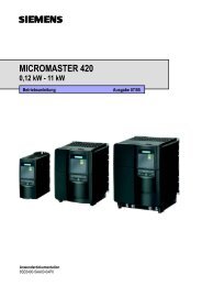
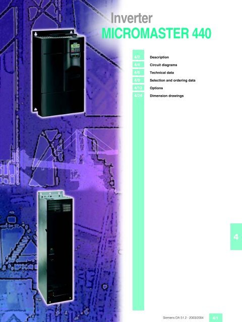
<strong>Inverter</strong><br />
<strong>MICROMASTER</strong> <strong>440</strong><br />
4/2 Description<br />
4/4 Circuit diagrams<br />
4/6 Technical data<br />
4/9 Selection and ordering data<br />
4/12 Options<br />
4/24 Dimension drawings<br />
4<br />
Siemens DA 51.2 · 2003/2004 4/1
<strong>MICROMASTER</strong> <strong>440</strong><br />
Description<br />
4<br />
■ Applications ■ Design ■ Main characteristics<br />
The <strong>MICROMASTER</strong> <strong>440</strong> inverter<br />
is suitable for a variety<br />
of variable-speed drive applications.<br />
Its flexibility provides<br />
for a wide spectrum of applications.<br />
These also include<br />
cranes and hoisting gear,<br />
high-bay warehouses, production<br />
machines for food,<br />
beverages and tobacco,<br />
packaging machines etc.; i.e.<br />
applications which require the<br />
frequency inverter to have a<br />
higher functionality and dynamic<br />
response than usual.<br />
The inverter is especially characterized<br />
by its customer-oriented<br />
performance and easeof-use.<br />
Its large mains voltage<br />
range enables it to be used all<br />
over the world.<br />
The <strong>MICROMASTER</strong> <strong>440</strong> inverter<br />
has a modular design.<br />
The operator panels and modules<br />
can be easily exchanged.<br />
■ International standards<br />
■ The <strong>MICROMASTER</strong> <strong>440</strong><br />
inverter complies with the<br />
requirements of the EU lowvoltage<br />
guideline<br />
■ The <strong>MICROMASTER</strong> <strong>440</strong><br />
inverter has the > marking<br />
■ acc. to u and cu certified<br />
■ c-tick ●✔<br />
Note:<br />
■ See Appendix for standards.<br />
■ Easy, guided start-up<br />
■ Modular construction allows<br />
maximum configuration<br />
flexibility<br />
■ Six programmable isolated<br />
digital inputs<br />
■ Two scaleable analog inputs<br />
(0 V to 10 V, 0 mA to<br />
20 mA) can also be used as<br />
a 7th/8th digital input<br />
■ Two programmable analog<br />
outputs (0 mA to 20 mA)<br />
■ Three programmable relay<br />
outputs (30 V DC/5 A resistive<br />
load; 250 V AC/2A inductive<br />
load)<br />
■ Low-noise motor operation<br />
thanks to high pulse frequencies,<br />
adjustable (observe<br />
derating if necessary)<br />
■ Complete protection for<br />
motor and inverter.<br />
■ Options (overview)<br />
■ EMC filter, Class A/B<br />
■ LC filter<br />
■ Line commutating chokes<br />
■ Output chokes<br />
■ Gland plates<br />
■ Basic Operator Panel<br />
(BOP) for parameterizing<br />
the inverter<br />
■ Plain text Advanced Operator<br />
Panel (AOP) with multilanguage<br />
display<br />
■ Plain text Asian Advanced<br />
Operator Panel (AAOP)<br />
with Chinese and English<br />
display<br />
■ Communication modules<br />
– PROFIBUS<br />
– DeviceNet<br />
–CANopen<br />
■ Pulse encoder evaluation<br />
module<br />
■ PC connection kits<br />
■ Mounting kits for installing<br />
the operator panels in the<br />
control cabinet doors<br />
■ PC start-up tools executable<br />
under Windows 95/98<br />
and NT/2000/<br />
XP Professional.<br />
■ TIA integration with<br />
Drive ES<br />
4/2 Siemens DA 51.2 · 2003/2004
<strong>MICROMASTER</strong> <strong>440</strong><br />
Description<br />
■ Mechanical features ■ Performance features ■ Protection features<br />
■ Modular design<br />
■ Operating temperature<br />
0.12 kW to 75 kW:<br />
–10 °C to +50 °C<br />
(+14 °F to +122 °F)<br />
90 kW to 200 kW:<br />
0 °C to +40 °C<br />
(+32 °F to +104 °F)<br />
■ Compact housing as a result<br />
of high power density<br />
■ Easy cable connection,<br />
mains and motor connections<br />
are separated for optimum<br />
electromagnetic compatibility<br />
■ Detachable operator<br />
panels<br />
■ Screwless control terminals<br />
on detachable I/O board.<br />
■ Latest IGBT technology<br />
■ Digital microprocessor<br />
control<br />
■ High-quality Vector Control<br />
system<br />
■ Flux Current Control (FCC)<br />
for improved dynamic response<br />
and optimized motor<br />
control<br />
■ Linear V/f characteristic<br />
■ Quadratic V/f characteristic<br />
■ Multipoint characteristic<br />
(programmable V/f characteristic)<br />
■ Torque control<br />
■ Flying restart<br />
■ Slip compensation<br />
■ Automatic restart following<br />
mains failure or fault<br />
■ User-definable function<br />
blocks for logic and arithmetic<br />
operations<br />
■ Kinetic buffering<br />
■ Positioning ramp down<br />
■ High-grade PID controller<br />
for simple internal process<br />
control (autotuning)<br />
■ Programmable acceleration/deceleration,<br />
0 s to<br />
650 s<br />
■ Ramp smoothing<br />
■ Fast Current Limit (FCL) for<br />
trip-free operation<br />
■ Fast, repeatable digital input<br />
response time<br />
■ Fine adjustment using two<br />
high-resolution 10-bit analog<br />
inputs<br />
■ Compound braking for controlled<br />
rapid braking<br />
■ Integrated brake chopper<br />
(for 0.12 kW to 75 kW inverters)<br />
■ Four skip frequencies<br />
■ Removable “Y” capacitor<br />
for use on IT systems (with<br />
non-grounded mains supplies,<br />
the “Y” capacitor<br />
must be removed and an<br />
output choke installed).<br />
■ Overload capability<br />
–CT mode<br />
0.12 kW to 75 kW:<br />
Overload current 1.5 x<br />
rated output current (i.e.<br />
150 % overload capability)<br />
for 60 s, cycle time<br />
300 s, and 2 x rated output<br />
current (i.e. 200 %<br />
overload capability) for<br />
3 s, cycle time 300 s<br />
90 kW to 200 kW:<br />
Overload current 1.36 x<br />
rated output current (i.e.<br />
136 % overload capability)<br />
for 57 s, cycle time<br />
300 s, and 1.6 x rated output<br />
current (i.e. 160 %<br />
overload capability) for<br />
3 s, cycle time 300 s<br />
–VT mode<br />
5.5 kW to 90 kW:<br />
Overload current 1.4 x<br />
rated output current (i.e.<br />
140 % overload capability)<br />
for 3 s, and 1.1 x rated<br />
output current (i.e. 110 %<br />
overload capability) for<br />
60 s, cycle time 300 s<br />
110 kW to 250 kW:<br />
Overload current 1.5 x<br />
rated output current (i.e.<br />
150 % overload capability)<br />
for 1 s, and 1.1 x rated<br />
output current (i.e. 110 %<br />
overload capability) for<br />
59 s, cycle time 300 s<br />
■ Overvoltage/undervoltage<br />
protection<br />
■ <strong>Inverter</strong> overtemperature<br />
protection<br />
■ Special direct connection<br />
for PTC or KTY to protect<br />
the motor<br />
■ Earth fault protection<br />
■ Short-circuit protection<br />
■ I 2 t motor thermal protection<br />
■ Locked motor protection<br />
■ Stall prevention<br />
■ Parameter interlock.<br />
4<br />
Siemens DA 51.2 · 2003/2004 4/3
<strong>MICROMASTER</strong> <strong>440</strong><br />
Circuit diagrams<br />
■ General circuit diagram<br />
F A H= J HF = A F JE <br />
1 <br />
C 2<br />
J " 8 ! ) +<br />
! & J " & 8 ! ) + <br />
# J $ 8 ! ) + <br />
2 -<br />
5 <br />
<br />
8<br />
8<br />
" % 9<br />
) 1 <br />
!<br />
)<br />
) 1 <br />
,<br />
"<br />
) 1 <br />
<br />
)<br />
) 1 <br />
,<br />
<br />
, 1 <br />
#<br />
, 1<br />
$<br />
, 1 !<br />
%<br />
, 1 "<br />
, 1 #<br />
&<br />
$<br />
, 1 $<br />
%<br />
2 2<br />
H<br />
'<br />
2 <br />
2 6 + )<br />
&<br />
)<br />
J H<br />
"<br />
2 6 + 6 ;<br />
2 6 + *<br />
,<br />
#<br />
F J EI = JE <br />
K JF K J " 8 <br />
EI = JA @ <br />
K JF K J 8 <br />
EI = JA @ <br />
+ 2 7<br />
* 2<br />
5 A HE= <br />
2 H J ? <br />
2 -<br />
) +<br />
<br />
<br />
H<br />
!<br />
, +<br />
* <br />
, + <br />
* , + <br />
H= @ @ EJE = @ EC EJ= E F K JI<br />
, 1 % , 1 & A N JA H = <br />
? A ? JE I I D K @ > A = @ A <br />
, 1 %<br />
<br />
!<br />
"<br />
, 1 &<br />
<br />
<br />
<br />
JA I <br />
9 D A = = = C E F K JEI<br />
? BEC K HA @ = I = @ EC EJ= E F K J<br />
JD A JD HA I D @ L = K A I = HA = I<br />
B M I <br />
% # 8 , + BB<br />
! % 8 , + <br />
) 1 8 J 8 ) J )<br />
= @ 8 J 8<br />
) 1 8 J 8<br />
= @ ) J )<br />
* H= E C<br />
HA I EI J H<br />
' 9 J 9 E L A HJA HI @ J<br />
D = L A = E JA C H= JA @ > H= E C ? D F F A H<br />
4<br />
) <br />
= N # 9<br />
) <br />
= N # 9<br />
K JF K JHA = O<br />
? J= ? JI<br />
# 8 ) + = N )<br />
E @ K ? JEL A = @ <br />
! 8 , + = N # )<br />
HA I EI JEL A = @ <br />
9 D A = ? K E? = JE I<br />
@ K A EI ? A ? JA @ <br />
JD A I A HE= E JA HB= ? A<br />
@ A I JM H <br />
) 7 6 <br />
) 7 6 <br />
) 7 6 <br />
) 7 6 <br />
4 +<br />
4 *<br />
4 )<br />
4 +<br />
4 *<br />
4 ! +<br />
4 ! *<br />
4 ! )<br />
2 <br />
<br />
<br />
!<br />
$<br />
%<br />
<br />
'<br />
&<br />
<br />
#<br />
"<br />
!<br />
'<br />
! <br />
)<br />
)<br />
,<br />
,<br />
4 5 " & #<br />
4 <br />
4 <br />
4 !<br />
$ 0 <br />
J<br />
K I A @<br />
# 0 <br />
<br />
, 12 5 M EJ? D A I<br />
+ JH * = H@ <br />
)<br />
) 1 ) 1<br />
8<br />
<br />
, 12 5 M EJ? D A I<br />
1 * = H@ <br />
, +<br />
2 -<br />
) +<br />
7 8 9<br />
) +<br />
, +<br />
, +<br />
) +<br />
, <br />
+ <br />
+ A ? JE <br />
B H<br />
A N JA H = <br />
> H= E C<br />
K EJ<br />
/ , ) # - # " C<br />
<br />
! <br />
4/4 Siemens DA 51.2 · 2003/2004
<strong>MICROMASTER</strong> <strong>440</strong><br />
Circuit diagrams<br />
■ Terminal connection diagram<br />
Example, frame size FX<br />
Mains connections<br />
View A<br />
Motor connections<br />
View A<br />
<br />
<br />
<br />
<br />
<br />
<br />
<br />
<br />
<br />
<br />
<br />
<br />
<br />
<br />
<br />
<br />
<br />
<br />
<br />
<br />
<br />
<br />
4<br />
<br />
<br />
<br />
<br />
<br />
<br />
<br />
<br />
<br />
<br />
<br />
<br />
Siemens DA 51.2 · 2003/2004 4/5
<strong>MICROMASTER</strong> <strong>440</strong><br />
Technical data<br />
■ <strong>MICROMASTER</strong> <strong>440</strong> inverter<br />
4<br />
Mains voltage and<br />
power ranges 1 AC 200 V to 240 V ± 10%<br />
3 AC 200 V to 240 V ± 10 %<br />
3 AC 380 V to 480 V ± 10 %<br />
3 AC 500 V to 600 V ± 10%<br />
Input frequency<br />
47 Hz to 63 Hz<br />
Output<br />
0.12 kW to 75 kW 0 Hz to 650 Hz (in V/f mode)<br />
frequency 90 kW to 200 kW 0 Hz to 267 Hz (in V/f mode)<br />
Power factor ˜ 0.95<br />
<strong>Inverter</strong> efficiency 96 % to 97 %<br />
Overload capability<br />
– CT mode 0.12 kW to 75 kW<br />
90 kW to 200 kW<br />
– VT mode 5.5 kW to 90 kW<br />
110 kW to 250 kW<br />
CT (constant torque)<br />
0.12 kW to 3 kW<br />
0.12 kW to 45 kW<br />
0.37 kW to 200 kW<br />
0.75 kW to 75 kW<br />
0 Hz to 200 Hz (in vector mode)<br />
0 Hz to 200 Hz (in vector mode)<br />
VT (variable torque)<br />
–<br />
5.5 kW to 45 kW<br />
7.5 kW to 250 kW<br />
1.5 kW to 90 kW<br />
Overload current 1.5 x rated output current (i.e. 150 % overload capability) for 60 s, cycle time 300 s<br />
and 2 x rated output current (i.e. 200 % overload capability) for 3 s, cycle time 300 s<br />
Overload current 1.36 x rated output current (i.e. 136 % overload capability) for 57 s, cycle time 300 s<br />
and 1.6 x rated output current (i.e. 160 % overload capability) for 3 s, cycle time 300 s<br />
Overload current 1.4 x rated output current (i.e. 140% overload capability) for 3 s,<br />
and 1.1 x rated output current (i.e. 110 % overload capability) for 60 s, cycle time 300 s<br />
Overload current 1.5 x rated output current (i.e. 150 % overload capability) for 1 s,<br />
and 1.1 x rated output current (i.e. 110 % overload capability) for 59 s, cycle time 300 s<br />
Inrush current<br />
not higher than rated input current<br />
Control method<br />
Vector control, torque control, linear V/f characteristic; quadratic V/f characteristic;<br />
Multipoint characteristic (programmable V/f characteristic); flux current control (FCC)<br />
Pulse frequency 0.12 kW to 75 kW<br />
90 kW to 200 kW<br />
4 kHz (standard); 16 kHz (standard with 230 V inverters 0.12 kW to 5.5 kW)<br />
2 kHz to 16 kHz (in 2 kHz steps)<br />
2 kHz (standard with VT mode); 4 kHz (standard with CT mode)<br />
2 kHz to 4 kHz (in 2 kHz steps)<br />
Fixed frequencies<br />
15, programmable<br />
Skip frequency ranges<br />
4, programmable<br />
Setpoint resolution<br />
0.01 Hz digital<br />
0.01 Hz serial<br />
10 bit analog<br />
Digital inputs<br />
6 fully programmable isolated digital inputs; switchable PNP/NPN<br />
Analog inputs<br />
2 programmable analog inputs<br />
• 0 V to 10 V, 0 mA to 20 mA and –10 V to +10 V (AIN1)<br />
• 0 V to 10 V and 0 mA to 20 mA (AIN2)<br />
• both can be used as 7th/8th digital input<br />
Relay outputs<br />
3, programmable, 30 V DC/5 A (resistive load); 250 V AC/2A (inductive load)<br />
Analog outputs<br />
2, programmable (0/4 mA to 20 mA)<br />
Serial interfaces<br />
RS-485, optional RS-232<br />
Motor cable lengths<br />
without output choke<br />
with output choke<br />
0.12 – 75 kW<br />
90 – 250 kW<br />
Electromagnetic compatibility<br />
(see Selection and Ordering Data)<br />
Braking<br />
Degree of protection<br />
Operating 0.12 kW to 75 kW<br />
temperature<br />
(without derating) 90 kW to 200 kW<br />
Storage temperature<br />
Relative humidity<br />
Installation altitude 0.12 kW to 75 kW<br />
90 kW to 200 kW<br />
max. 50 m (shielded), max. 100 m (unshielded)<br />
max. 100 m (shielded), max. 150 m (unshielded)<br />
(see variant dependent options)<br />
EMC filter, Class A or Class B to EN 55 011 available as an option<br />
<strong>Inverter</strong> with internal filter Class A available<br />
Resistance braking with DC braking, compound braking, integrated brake chopper<br />
(integrated brake chopper only with 0.12 kW to 75 kW inverters)<br />
IP20<br />
CT: –10 °C to +122.00 °F (+14 °F to +122 °F)<br />
VT: –10 °C to +40 °C (+14 °F to +104 °F)<br />
0 °C to +40 °C (+32 °F to +104 °F)<br />
–40 °C to +70 °C (–40 °F to +158 °F)<br />
95% (non-condensing)<br />
up to 1000 m above sea level without derating<br />
up to 2000 m above sea level without derating<br />
Protection features for<br />
Undervoltage, overvoltage, overload, earth faults, short-circuits, stall prevention, locked motor protection,<br />
motor over-temperature, inverter overtemperature, parameter change protection<br />
Compliance with standards<br />
u, cu, >, c-tick ●✔<br />
> marking Conformity with low-voltage directive 73/23/EEC<br />
Dimensions and weights<br />
(without options)<br />
Frame size (FS)<br />
A<br />
B<br />
C<br />
D<br />
E<br />
F without filter<br />
F with filter<br />
FX<br />
GX<br />
H x W x D, max. (mm)<br />
173 x 73 x 149<br />
202 x 149 x 172<br />
245 x 185 x 195<br />
520 x 275 x 245<br />
650 x 275 x 245<br />
850 x 350 x 320<br />
1150 x 350 x 320<br />
1400 x 326 x 356<br />
1533 x 326 x 545<br />
Weight, approx. (kg)<br />
1.3<br />
3.4<br />
5.7<br />
17<br />
22<br />
56<br />
75<br />
116<br />
176<br />
4/6 Siemens DA 51.2 · 2003/2004
<strong>MICROMASTER</strong> <strong>440</strong><br />
Technical data<br />
■ Derating data<br />
Pulse frequency<br />
Output<br />
Rated output current in A<br />
for a pulse frequency of<br />
kW 4 kHz 6 kHz 8 kHz 10 kHz 12 kHz 14 kHz 16 kHz<br />
Mains voltage 1/3 AC 200 V<br />
0.12 to 5.5 Values correspond to the 4 kHz standard values.<br />
No derating, since 16 kHz standard.<br />
7.5 28.0 26.6 25.2 22.4 19.6 16.8 14.0<br />
11 42.0 37.8 33.6 29.4 25.2 21.0 16.8<br />
15 54.0 48.6 43.2 37.8 32.4 27.0 21.6<br />
18.5 68.0 64.6 61.2 54.4 47.6 40.8 34.0<br />
22 80.0 72.0 64.0 56.0 48.0 40.0 32.0<br />
30 104.0 91.0 78.0 70.2 62.4 57.2 52.0<br />
37 130.0 113.8 97.5 87.8 78.0 71.5 65.0<br />
45 154.0 134.8 115.5 104.0 92.4 84.7 77.0<br />
Mains operating voltage 3 AC 400 V<br />
0.37 1.3 1.3 1.3 1.3 1.3 1.2 1.0<br />
0.55 1.7 1.7 1.7 1.6 1.5 1.4 1.2<br />
0.75 2.2 2.2 2.2 2.0 1.8 1.5 1.3<br />
1.1 3.1 2.9 2.8 2.5 2.2 1.9 1.6<br />
1.5 4.1 3.7 3.3 2.9 2.5 2.1 1.6<br />
2.2 5.9 5.6 5.3 4.7 4.1 3.5 3.0<br />
3.0 7.7 6.9 6.2 5.4 4.6 3.9 3.1<br />
4.0 10.2 9.2 8.2 7.1 6.1 5.1 4.1<br />
5.5 13.2 11.9 10.6 9.2 7.9 6.6 5.3<br />
7.5 19.0 18.1 17.1 15.2 13.3 11.4 9.5<br />
11.0 26.0 23.4 20.8 18.2 15.6 13.0 10.4<br />
15.0 32.0 30.4 28.8 25.6 22.4 19.2 16.0<br />
18.5 38.0 34.2 30.4 26.6 22.8 19.0 15.2<br />
22 45.0 40.5 36.0 31.5 27.0 22.5 18.0<br />
30 62.0 58.9 55.8 49.6 43.4 37.2 31.0<br />
37 75.0 67.5 60.0 52.5 45.0 37.5 30.0<br />
45 90.0 76.5 63.0 51.8 40.5 33.8 27.0<br />
55 110.0 93.5 77.0 63.3 49.5 41.3 33.0<br />
75 145.0 112.4 79.8 68.9 58.0 50.8 43.5<br />
90 178.0 – – – – – –<br />
110 205.0 – – – – – –<br />
132 250.0 – – – – – –<br />
160 302.0 – – – – – –<br />
200 370.0 – – – – – –<br />
Mains operating voltage 3 AC 500 V<br />
0.75 1.4 1.2 1.0 0.8 0.7 0.6 0.6<br />
1.5 2.7 2.2 1.6 1.4 1.1 0.9 0.8<br />
2.2 3.9 2.9 2.0 1.6 1.2 1.0 0.8<br />
4.0 6.1 4.6 3.1 2.4 1.8 1.5 1.2<br />
5.5 9.0 6.8 4.5 3.6 2.7 2.3 1.8<br />
7.5 11.0 8.8 6.6 5.5 4.4 3.9 3.3<br />
11.0 17.0 12.8 8.5 6.8 5.1 4.3 3.4<br />
15.0 22.0 17.6 13.2 11.0 8.8 7.7 6.6<br />
18.5 27.0 20.3 13.5 10.8 8.1 6.8 5.4<br />
22 32.0 24.0 16.0 12.8 9.6 8.0 6.4<br />
30 41.0 32.8 24.6 20.5 16.4 14.4 12.3<br />
37 52.0 39.0 26.0 20.8 15.6 13.0 10.4<br />
45 62.0 52.7 43.4 40.3 37.2 32.6 27.9<br />
55 77.0 67.4 57.8 52.0 46.2 42.4 38.5<br />
75 99.0 84.2 69.3 64.4 59.4 52.0 44.6<br />
4<br />
Siemens DA 51.2 · 2003/2004 4/7
<strong>MICROMASTER</strong> <strong>440</strong><br />
Technical data<br />
■ Derating data (continued)<br />
Operating temperature<br />
<strong>Inverter</strong> 0.12 kW to 75 kW<br />
Rated output current<br />
100<br />
%<br />
80<br />
70<br />
60<br />
50<br />
40<br />
20<br />
G_DA51_EN_05026c<br />
VT<br />
CT<br />
<strong>Inverter</strong> 90 kW to 200 kW<br />
4 = JA @ K JF K J? K HHA J<br />
<br />
& #<br />
& <br />
<br />
$ <br />
" <br />
<br />
) , ) # # " % =<br />
0<br />
-10 0 10 20 30 40 50 60 °C 70<br />
Operating temperature<br />
<br />
<br />
<br />
! " " # + # #<br />
F A H= JE C JA F A H= JK HA<br />
Installation height above sea level<br />
Permissible output current<br />
in % of the rated output current<br />
<strong>Inverter</strong> 0.12 kW to 75 kW<br />
<strong>Inverter</strong> 90 kW to 200 kW<br />
Rated output current<br />
100<br />
%<br />
80<br />
60<br />
40<br />
20<br />
ADA51-5018c<br />
<br />
<br />
<br />
<br />
<br />
<br />
<br />
<br />
<br />
0<br />
0 1000 2000 3000 m 4000<br />
Operational altitude<br />
<br />
<br />
<br />
<br />
<br />
Permissible mains voltage<br />
in % of the max. possible mains voltage<br />
4<br />
<strong>Inverter</strong> 0.12 kW to 75 kW<br />
Mains voltage<br />
100<br />
%<br />
80<br />
77<br />
ADA51-5019b<br />
60<br />
40<br />
20<br />
0<br />
0 1000 2000 3000 m 4000<br />
Operational altitude<br />
<strong>Inverter</strong> 90 kW to 200 kW<br />
Mains voltage<br />
100<br />
%<br />
80<br />
77<br />
ADA51-5019b<br />
60<br />
40<br />
20<br />
0<br />
0 1000 2000 3000 m 4000<br />
Operational altitude<br />
4/8 Siemens DA 51.2 · 2003/2004
<strong>MICROMASTER</strong> <strong>440</strong><br />
Selection and ordering data<br />
■ <strong>MICROMASTER</strong> <strong>440</strong> inverter without filter 2 )<br />
CT (constant torque) VT (variable torque) <strong>MICROMASTER</strong> <strong>440</strong> without filter 2 )<br />
Output Rated input Rated output Output Rated input Rated output Frame Weight, Order No.<br />
current 1 ) current<br />
current 1 ) current size approx.<br />
kW hp A A kW hp A A (FS) kg<br />
Mains voltage 1 AC 200 V to 240 V<br />
0.12 0.16 2.3 0.9 – – – – A 1.3 6SE6<strong>440</strong>-2UC11-2AA1<br />
0.25 0.33 4.3 1.7 – – – – A 1.3 6SE6<strong>440</strong>-2UC12-5AA1<br />
0.37 0.50 5.9 2.3 – – – – A 1.3 6SE6<strong>440</strong>-2UC13-7AA1<br />
0.55 0.75 7.7 3.0 – – – – A 1.3 6SE6<strong>440</strong>-2UC15-5AA1<br />
0.75 1.0 10.1 3.9 – – – – A 1.3 6SE6<strong>440</strong>-2UC17-5AA1<br />
1.1 1.5 15.0 5.5 – – – – B 3.3 6SE6<strong>440</strong>-2UC21-1BA1<br />
1.5 2 18.6 7.4 – – – – B 3.3 6SE6<strong>440</strong>-2UC21-5BA1<br />
2.2 3 26.8 10.4 – – – – B 3.3 6SE6<strong>440</strong>-2UC22-2BA1<br />
3.0 4 35.9 13.6 – – – – C 5.5 6SE6<strong>440</strong>-2UC23-0CA1<br />
Mains operating voltage 3 AC 200 V to 240 V<br />
0.12 0.16 1.1 0.9 – – – – A 1.3 6SE6<strong>440</strong>-2UC11-2AA1<br />
0.25 0.33 2.2 1.7 – – – – A 1.3 6SE6<strong>440</strong>-2UC12-5AA1<br />
0.37 0.50 3.0 2.3 – – – – A 1.3 6SE6<strong>440</strong>-2UC13-7AA1<br />
0.55 0.75 3.9 3.0 – – – – A 1.3 6SE6<strong>440</strong>-2UC15-5AA1<br />
0.75 1.0 5.2 3.9 – – – – A 1.3 6SE6<strong>440</strong>-2UC17-5AA1<br />
1.1 1.5 7.6 5.5 – – – – B 3.3 6SE6<strong>440</strong>-2UC21-1BA1<br />
1.5 2.0 10.2 7.4 – – – – B 3.3 6SE6<strong>440</strong>-2UC21-5BA1<br />
2.2 3.0 14.1 10.4 – – – – B 3.3 6SE6<strong>440</strong>-2UC22-2BA1<br />
3.0 4.0 18.4 13.6 – – – – C 5.5 6SE6<strong>440</strong>-2UC23-0CA1<br />
4.0 5.0 23.3 17.5 5.5 7.5 28.3 22 C 5.5 6SE6<strong>440</strong>-2UC24-0CA1<br />
5.5 7.5 28.0 22 7.5 10 34.2 28 C 5.5 6SE6<strong>440</strong>-2UC25-5CA1<br />
7.5 10 34.0 28 11.0 15 48.7 42 D 16 6SE6<strong>440</strong>-2UC27-5DA1<br />
11.0 15 50.6 42 15.0 20 63.1 54 D 16 6SE6<strong>440</strong>-2UC31-1DA1<br />
15.0 20 64.9 54 18.5 25 80.2 68 D 16 6SE6<strong>440</strong>-2UC31-5DA1<br />
18.5 25 83.0 68 22 30 96.0 80 E 20 6SE6<strong>440</strong>-2UC31-8EA1<br />
22 30 100.0 80 30 40 127.0 104 E 20 6SE6<strong>440</strong>-2UC32-2EA1<br />
30 40 140.0 104 37 50 171.0 130 F 55 6SE6<strong>440</strong>-2UC33-0FA1<br />
37 50 177.0 130 45 60 206.0 154 F 55 6SE6<strong>440</strong>-2UC33-7FA1<br />
45 60 204.0 154 – – – – F 55 6SE6<strong>440</strong>-2UC34-5FA1<br />
Mains operating voltage 3 AC 380 V to 480 V<br />
0.37 0.50 1.5 1.3 – – – – A 1.3 6SE6<strong>440</strong>-2UD13-7AA1<br />
0.55 0.75 1.9 1.7 – – – – A 1.3 6SE6<strong>440</strong>-2UD15-5AA1<br />
0.75 1.0 2.4 2.2 – – – – A 1.3 6SE6<strong>440</strong>-2UD17-5AA1<br />
1.1 1.5 3.7 3.1 – – – – A 1.3 6SE6<strong>440</strong>-2UD21-1AA1<br />
1.5 2.0 4.8 4.1 – – – – A 1.3 6SE6<strong>440</strong>-2UD21-5AA1<br />
2.2 3.0 6.5 5.9 – – – – B 3.3 6SE6<strong>440</strong>-2UD22-2BA1<br />
3.0 4.0 8.6 7.7 – – – – B 3.3 6SE6<strong>440</strong>-2UD23-0BA1<br />
4.0 5.0 11.6 10.2 – – – – B 3.3 6SE6<strong>440</strong>-2UD24-0BA1<br />
5.5 7.5 15.6 13.2 7.5 10 20.2 19 C 5.5 6SE6<strong>440</strong>-2UD25-5CA1<br />
7.5 10 22.0 19 11.0 15 29.0 26 C 5.5 6SE6<strong>440</strong>-2UD27-5CA1<br />
11.0 15 32.3 26 15.0 20 39.0 32 C 5.5 6SE6<strong>440</strong>-2UD31-1CA1<br />
15.0 20 38.5 32 18.5 25 45.2 38 D 16 6SE6<strong>440</strong>-2UD31-5DA1<br />
18.5 25 47.1 38 22 30 54.7 45 D 16 6SE6<strong>440</strong>-2UD31-8DA1<br />
22 30 56.3 45 30 40 74.8 62 D 16 6SE6<strong>440</strong>-2UD32-2DA1<br />
30 40 78.0 62 37 50 91.0 75 E 20 6SE6<strong>440</strong>-2UD33-0EA1<br />
37 50 95.0 75 45 60 111.0 90 E 20 6SE6<strong>440</strong>-2UD33-7EA1<br />
45 60 122.0 90 55 75 143.0 110 F 56 6SE6<strong>440</strong>-2UD34-5FA1<br />
55 75 148.0 110 75 100 190.0 145 F 56 6SE6<strong>440</strong>-2UD35-5FA1<br />
75 100 188.0 145 90 125 223.0 178 F 56 6SE6<strong>440</strong>-2UD37-5FA1<br />
4<br />
1) Supplementary conditions:<br />
Input current at rated operating<br />
point, applicable at short-circuit<br />
voltage of the supply<br />
U sc = 1 % with reference to the<br />
inverter rated power and rated<br />
mains operating voltage of<br />
240 V or 400 V without a line<br />
commutating choke.<br />
When a line commutating choke<br />
is used, the specified values are<br />
reduced in the case of<br />
200 V–240 V to between 55% to<br />
70% and in the case of<br />
380 V–480 V to between 70%<br />
and 80%.<br />
2) Generally suited to heavy<br />
industrial applications. For details<br />
please refer to Appendix on<br />
page A/4.<br />
Siemens DA 51.2 · 2003/2004 4/9
<strong>MICROMASTER</strong> <strong>440</strong><br />
Selection and ordering data<br />
■ <strong>MICROMASTER</strong> <strong>440</strong> inverter without filter 3 ) (continued)<br />
CT (constant torque) VT (variable torque) <strong>MICROMASTER</strong> <strong>440</strong> without filter 3 )<br />
Output Rated input Rated output Output Rated input Rated output Frame Weight, Order No.<br />
current current<br />
current current size approx.<br />
kW hp A A kW hp A A (FS) kg<br />
Mains operating voltage 3 AC 380 V to 480 V<br />
90 125 168.5 1 ) 178 110 150 204.5 1 ) 205 FX 110 6SE6<strong>440</strong>-2UD38-8FA1<br />
110 150 204.0 1 ) 205 132 200 244.5 1 ) 250 FX 116 6SE6<strong>440</strong>-2UD41-1FA1<br />
132 200 244.5 1 ) 250 160 250 296.4 1 ) 302 GX 170 6SE6<strong>440</strong>-2UD41-3GA1<br />
160 250 296.4 1 ) 302 200 300 354.0 1 ) 370 GX 174 6SE6<strong>440</strong>-2UD41-6GA1<br />
200 300 354.0 1 ) 370 250 350 442.0 1 ) 477 GX 176 6SE6<strong>440</strong>-2UD42-0GA1<br />
Mains operating voltage 3 AC 500 V to 600 V<br />
0.75 1.0 2.0 2 ) 1.4 1.5 2.0 3.8 2 ) 2.7 C 5.5 6SE6<strong>440</strong>-2UE17-5CA1<br />
1.5 2.0 3.7 2 ) 2.7 2.2 3.0 5.3 2 ) 3.9 C 5.5 6SE6<strong>440</strong>-2UE21-5CA1<br />
2.2 3.0 5.3 2 ) 3.9 4.0 5.0 8.2 2 ) 6.1 C 5.5 6SE6<strong>440</strong>-2UE22-2CA1<br />
4.0 5.0 8.1 2 ) 6.1 5.5 7.5 11.2 2 ) 9 C 5.5 6SE6<strong>440</strong>-2UE24-0CA1<br />
5.5 7.5 11.1 2 ) 9 7.5 10 13.3 2 ) 11 C 5.5 6SE6<strong>440</strong>-2UE25-5CA1<br />
7.5 10 14.4 2 ) 11 11.0 15 21.7 2 ) 17 C 5.5 6SE6<strong>440</strong>-2UE27-5CA1<br />
11.0 15 21.5 2 ) 17 15.0 20 26.8 2 ) 22 C 5.5 6SE6<strong>440</strong>-2UE31-1CA1<br />
15.0 20 27.6 2 ) 22 18.5 25 32.7 2 ) 27 D 16 6SE6<strong>440</strong>-2UE31-5DA1<br />
18.5 25 33.6 2 ) 27 22 30 39.9 2 ) 32 D 16 6SE6<strong>440</strong>-2UE31-8DA1<br />
22 30 40.1 2 ) 32 30 40 50.5 2 ) 41 D 16 6SE6<strong>440</strong>-2UE32-2DA1<br />
30 40 52.0 2 ) 41 37 50 64.0 2 ) 52 E 20 6SE6<strong>440</strong>-2UE33-0EA1<br />
37 50 67.0 2 ) 52 45 60 78.0 2 ) 62 E 20 6SE6<strong>440</strong>-2UE33-7EA1<br />
45 60 85.0 2 ) 62 55 75 103.0 2 ) 77 F 56 6SE6<strong>440</strong>-2UE34-5FA1<br />
55 75 106.0 2 ) 77 75 100 132.0 2 ) 99 F 56 6SE6<strong>440</strong>-2UE35-5FA1<br />
75 100 130.0 2 ) 99 90 120 160.0 2 ) 125 F 56 6SE6<strong>440</strong>-2UE37-5FA1<br />
See Appendix for note on<br />
ordering.<br />
All <strong>MICROMASTER</strong> <strong>440</strong> inverters<br />
are supplied with a Status<br />
Display Panel (SDP). A BOP,<br />
AOP or other options have to<br />
be ordered separately (see<br />
Pages 4/14 to 4/20).<br />
■ Motors for<br />
<strong>MICROMASTER</strong> <strong>440</strong><br />
Catalog M 11 contains selection<br />
and ordering data for motors<br />
which are particularly suitable<br />
for operation with the<br />
<strong>MICROMASTER</strong> <strong>440</strong> inverters<br />
(see Appendix for overview).<br />
This catalog is suitable for IEC<br />
motors. For motors according<br />
to US standards (NEMA)<br />
please refer to:<br />
http://www.sea.siemens.com/<br />
motors<br />
4<br />
1) Supplementary conditions:<br />
Input current at rated operating<br />
point, applicable at short-circuit<br />
voltage of the supply<br />
U sc = 2.33 % with reference to<br />
the inverter rated power and<br />
rated mains operating voltage<br />
of 400 V.<br />
2) Supplementary conditions:<br />
Input current at rated operating<br />
point, applicable at short-circuit<br />
voltage of the supply<br />
U SC = 1 % with reference to the<br />
inverter rated power and rated<br />
mains operating voltage of<br />
500 V without a line commutating<br />
choke.<br />
If a line commutating choke is<br />
used, the specified values at<br />
500 V to 600 V are reduced to<br />
between 80% and 90%.<br />
3) Generally suited to heavy<br />
industrial applications. For details<br />
please refer to Appendix on<br />
page A/4.<br />
4/10 Siemens DA 51.2 · 2003/2004
<strong>MICROMASTER</strong> <strong>440</strong><br />
Selection and ordering data<br />
■ <strong>MICROMASTER</strong> <strong>440</strong> inverter with internal filter Class A<br />
CT (constant torque) VT (variable torque) <strong>MICROMASTER</strong> <strong>440</strong><br />
with internal filter Class A 2 )<br />
Output<br />
Rated input<br />
current 1 )<br />
Rated output<br />
current<br />
Output<br />
Rated input<br />
current 1 )<br />
Rated output<br />
current<br />
Frame<br />
size<br />
kW hp A A kW hp A A (FS) kg<br />
Weight,<br />
approx.<br />
Order No.<br />
Mains operating voltage 1 AC 200 V to 240 V<br />
0.12 0.16 2.3 0.9 – – – – A 1.3 6SE6<strong>440</strong>-2AB11-2AA1<br />
0.25 0.33 4.3 1.7 – – – – A 1.3 6SE6<strong>440</strong>-2AB12-5AA1<br />
0.37 0.50 5.9 2.3 – – – – A 1.3 6SE6<strong>440</strong>-2AB13-7AA1<br />
0.55 0.75 7.7 3.0 – – – – A 1.3 6SE6<strong>440</strong>-2AB15-5AA1<br />
0.75 1.0 10.1 3.9 – – – – A 1.3 6SE6<strong>440</strong>-2AB17-5AA1<br />
1.1 1.5 15.0 5.5 – – – – B 3.4 6SE6<strong>440</strong>-2AB21-1BA1<br />
1.5 2 18.6 7.4 – – – – B 3.4 6SE6<strong>440</strong>-2AB21-5BA1<br />
2.2 3 26.8 10.4 – – – – B 3.4 6SE6<strong>440</strong>-2AB22-2BA1<br />
3.0 4 35.9 13.6 – – – – C 5.7 6SE6<strong>440</strong>-2AB23-0CA1<br />
Mains operating voltage 3 AC 200 V to 240 V<br />
3.0 4.0 18.4 13.6 4.0 5.0 21.0 17.5 C 5.7 6SE6<strong>440</strong>-2AC23-0CA1<br />
4.0 5.0 23.3 17.5 5.5 7.5 28.3 22 C 5.7 6SE6<strong>440</strong>-2AC24-0CA1<br />
5.5 7.5 28.0 22.0 7.5 10.0 34.2 28 C 5.7 6SE6<strong>440</strong>-2AC25-5CA1<br />
Mains operating voltage 3 AC 380 V to 480 V<br />
2.2 3.0 6.5 5.9 – – – – B 3.4 6SE6<strong>440</strong>-2AD22-2BA1<br />
3.0 4.0 8.6 7.7 – – – – B 3.4 6SE6<strong>440</strong>-2AD23-0BA1<br />
4.0 5.0 11.6 10.2 – – – – B 3.4 6SE6<strong>440</strong>-2AD24-0BA1<br />
5.5 7.5 15.6 13.2 7.5 10 20.2 19 C 5.7 6SE6<strong>440</strong>-2AD25-5CA1<br />
7.5 10 22.0 18.4 11.0 15 29.0 26 C 5.7 6SE6<strong>440</strong>-2AD27-5CA1<br />
11.0 15 32.3 26 15.0 20 39.0 32 C 5.7 6SE6<strong>440</strong>-2AD31-1CA1<br />
15.0 20 38.5 32 18.5 25 45.2 38 D 17 6SE6<strong>440</strong>-2AD31-5DA1<br />
18.5 25 47.1 38 22 30 54.7 45 D 17 6SE6<strong>440</strong>-2AD31-8DA1<br />
22 30 56.3 45 30 40 74.8 62 D 17 6SE6<strong>440</strong>-2AD32-2DA1<br />
30 40 78.0 62 37 50 91.0 75 E 22 6SE6<strong>440</strong>-2AD33-0EA1<br />
37 50 95.0 75 45 60 111.0 90 E 22 6SE6<strong>440</strong>-2AD33-7EA1<br />
45 60 122.0 90 55 75 143.0 110 F 75 6SE6<strong>440</strong>-2AD34-5FA1<br />
55 75 148.0 110 75 100 190.0 145 F 75 6SE6<strong>440</strong>-2AD35-5FA1<br />
75 100 188.0 145 90 125 223.0 178 F 75 6SE6<strong>440</strong>-2AD37-5FA1<br />
See Appendix for note on ordering.<br />
All <strong>MICROMASTER</strong> <strong>440</strong> inverters<br />
are supplied with a Status<br />
Display Panel (SDP). A BOP,<br />
AOP or other options have to<br />
be ordered separately (see<br />
Pages 4/14 to 4/20).<br />
■ Motors for<br />
<strong>MICROMASTER</strong> <strong>440</strong><br />
Catalog M 11 contains selection<br />
and ordering data for motors<br />
which are particularly suitable<br />
for operation with the<br />
<strong>MICROMASTER</strong> <strong>440</strong> inverters<br />
(see Appendix for overview).<br />
This catalog is suitable for IEC<br />
motors. For motors according<br />
to US standards (NEMA)<br />
please refer to:<br />
http://www.sea.siemens.com/<br />
motors<br />
4<br />
1) Supplementary conditions:<br />
Input current at rated operating<br />
point, applicable at short-circuit<br />
voltage of the supply<br />
U sc = 1 % with reference to the<br />
inverter rated power and rated<br />
mains operating voltage of<br />
240 V or 400 V without a line<br />
commutating choke.<br />
When a line commutating choke<br />
is used, the specified values are<br />
reduced in the case of<br />
200 V–240 V to between 55% to<br />
70% and in the case of<br />
380 V–480 V to between 70%<br />
and 80%.<br />
2) Use of <strong>MICROMASTER</strong> inverters<br />
with internal filter is not permissible<br />
on non-grounded<br />
mains supplies.<br />
Siemens DA 51.2 · 2003/2004 4/11
<strong>MICROMASTER</strong> <strong>440</strong><br />
Options<br />
Variant dependent options<br />
■ Overview<br />
EMC filter, Class A<br />
Filter for inverters without an<br />
internal filter for<br />
• 3 AC 200 V to 240 V,<br />
frame sizes A and B<br />
• 3 AC 380 V to 480 V,<br />
frame size A, FX, GX<br />
Filters for frame sizes FX and<br />
GX are only permitted to be<br />
used in combination with a line<br />
commutating choke.<br />
All other inverters can be supplied<br />
with an internal Class A<br />
filter.<br />
The requirements are fulfilled<br />
using shielded cables with a<br />
max. length of 25 m.<br />
4<br />
EMC filter, Class B<br />
Filter for inverters without an<br />
internal filter for<br />
• 3 AC 200 V to 240 V,<br />
frame sizes A and B<br />
• 3 AC 380 V to 480 V,<br />
frame size A.<br />
The requirements are fulfilled<br />
using shielded cables with a<br />
max. length of 25 m.<br />
For inverters 15 kW to 75 kW<br />
without filters, EMC filters of<br />
Class B from Schaffner can be<br />
used.<br />
The requirements are fulfilled<br />
using shielded cables with a<br />
max. length of 25 m to 50 m<br />
(depending on the type, details<br />
on request).<br />
With this filter, the inverter<br />
complies with the emission<br />
standard EN 55 011, Class B.<br />
Additional EMC filter,<br />
Class B<br />
Available for inverters with an<br />
internal Class A EMC filter,<br />
frame sizes A, B and C.<br />
The requirements are fulfilled<br />
using shielded cables with a<br />
max. length of 25 m.<br />
With this filter, the inverter<br />
complies with the emission<br />
standard EN 55 011, Class B.<br />
Filter Class B with low<br />
leakage currents<br />
EMC filter for 1 AC 200 V to<br />
240 V inverters, frame sizes A<br />
and B, without an internal EMC<br />
filter Class A.<br />
With this filter, the inverter<br />
complies with the emission<br />
standard EN 55 011, Class B.<br />
The leakage currents are reduced<br />
to < 3.5 mA.<br />
The requirements are fulfilled<br />
using shielded cables with a<br />
max. length of 5 m.<br />
Leakage currents:<br />
The leakage currents of the inverters<br />
with/without filter (internal/external)<br />
may exceed<br />
30 mA. Typical values in practice<br />
are between 10 mA and<br />
50 mA. The exact values depend<br />
on the design, environment<br />
and cable lengths. Interference-free<br />
operation with residual<br />
current operated devices<br />
with a trigger value of<br />
30 mA cannot be guaranteed.<br />
However, operation with residual<br />
current circuit-breakers<br />
with a trigger value of 300 mA<br />
is possible. Please refer to the<br />
Instruction Manual for details.<br />
LC filter<br />
The LC filter limits the rate of<br />
rise of voltage and the capacitive<br />
charge/discharge currents<br />
which usually occur with<br />
inverter operation. This means<br />
that much longer shielded motor<br />
cables are possible when<br />
using LC filters and the service<br />
life of the motor achieves<br />
values similar to those with direct<br />
mains operation.<br />
The LC filters can be used for<br />
all <strong>MICROMASTER</strong> <strong>440</strong> inverters<br />
of frame sizes A to F.<br />
• Frame sizes A and B:<br />
A maximum of two footprint<br />
components plus inverter<br />
are permissible. The LC filter<br />
must be mounted as the lowest<br />
component.<br />
•Frame size C:<br />
Only one footprint component<br />
is permissible for frame<br />
size C. If a line choke and LC<br />
filter are used, the line choke<br />
must be located on the left of<br />
the inverter. Required spacing:<br />
75 mm.<br />
• Frame sizes D to F:<br />
The LC filters, frame sizes D<br />
to F, are designed for<br />
mounting upright in the control<br />
cabinet. Due to leakage<br />
flux lines caused by physical<br />
sources, a minimum distance<br />
of 50 mm to adjacent<br />
modules and metal parts is<br />
recommended.<br />
Please note when using<br />
LC filters:<br />
•Only V/f, FCC control<br />
permissible<br />
• Increased inverter load:<br />
approx. 10 % to 15 %<br />
• Operation only permissible<br />
with 4 kHz pulse frequency<br />
The output frequency is limited<br />
to 150 Hz.<br />
Line commutating choke<br />
Line commutating chokes are<br />
used to smooth voltage peaks<br />
or to bridge commutating<br />
dips. In addition, line commutating<br />
chokes reduce the effects<br />
of harmonics on the inverter<br />
and the power supply. If<br />
the line impedance is < 1 %, a<br />
line commutating choke must<br />
be used in order to reduce the<br />
current peaks.<br />
In line with EN 61 000-3-2 regulations<br />
“Limits for harmonic<br />
currents with device input current<br />
ˆ16 A per phase”, there<br />
are special aspects for drives<br />
with 250 W to 550 W and 230 V<br />
single-phase supplies which<br />
can be used in non-industrial<br />
applications (1st environment).<br />
For devices with 250 W and<br />
350 W, it is necessary either to<br />
fit the recommended input<br />
chokes or to apply to the<br />
power utility company for<br />
authorization to connect the<br />
devices to the public power<br />
supply.<br />
No limits are currently defined<br />
in the EN 61 000-3-2 standard<br />
for professionally used devices<br />
with a connected load<br />
>1 kW which means that the<br />
inverters with an output power<br />
˜ 0.75 kW comply with the<br />
EN 61 000-3-2 standard.<br />
Output choke<br />
Output chokes can be supplied<br />
for reducing the capacitive<br />
compensation currents<br />
and dV/dt in the case of motor<br />
cables >50 m (shielded) or<br />
>100 m (unshielded).<br />
For max. permissible cable<br />
lengths, see the Technical<br />
Data.<br />
Brake resistors<br />
The brake resistors are designed<br />
for use with the<br />
<strong>MICROMASTER</strong> <strong>440</strong> inverter<br />
series, frame sizes A to F, with<br />
internal brake chopper and<br />
enable loads with a large moment<br />
of inertia to be braked<br />
quickly. During braking of the<br />
motor and the load, excess<br />
energy is fed back to the inverter.<br />
This causes the voltage<br />
to rise in the DC link. The inverter<br />
transfers the excess energy<br />
to the externally mounted<br />
braking resistor.<br />
For <strong>MICROMASTER</strong> <strong>440</strong> inverters<br />
of frame sizes FX and<br />
GX, external SIMOVERT<br />
MASTERDRIVES brake units<br />
and the appropriate brake resistors<br />
can be used (see<br />
Catalog DA 65.10).<br />
Gland plate<br />
Gland plates are available for<br />
inverters of frame sizes A, B<br />
and C. In frame sizes D onwards,<br />
the gland plates are integrated.<br />
The gland plate enables the<br />
shields of the power and control<br />
cables to be terminated<br />
ensuring optimum EMC performance.<br />
4/12 Siemens DA 51.2 · 2003/2004
<strong>MICROMASTER</strong> <strong>440</strong><br />
Options<br />
Variant dependent options<br />
■ Technical data<br />
LC filter<br />
Mains voltage 3 AC 380 V to 480 V 3 AC 500 V to 600 V<br />
Current (at 40 °C/50 °C)<br />
For frame size A (0.37 to 1.5 kW)<br />
For frame size B (2.2 to 4 kW)<br />
For frame size C (0.75 to 4 kW)<br />
For frame size C (5.5 to 11 kW)<br />
For frame size D (15 kW)<br />
For frame size D (18.5 kW)<br />
For frame size D (22 kW)<br />
For frame size E (30 kW)<br />
For frame size E (37 kW)<br />
For frame size F (45 kW)<br />
For frame size F (55 kW)<br />
For frame size F (75 kW)<br />
Limiting of motor overvoltage<br />
dV/dt limiting<br />
Pulse frequency<br />
Max. motor frequency<br />
Max. permissible motor cable lengths Shielded<br />
Unshielded<br />
4.5 A/4.1 A –<br />
11.2 A/10.2 A –<br />
– 9.0 A/6.1 A<br />
32.6 A/29.7 A 22.4 A/17 A<br />
38.8 A/32 A 27.5 A/22 A<br />
32.6 A/38 A 22.4 A/27 A<br />
63.2 A/45 A 41.8 A/32 A<br />
76.5 A/62 A 53 A/41 A<br />
112.2 A/90 A 63.2 A/52 A<br />
112.2 A/90 A 78.5 A/62 A<br />
147.9 A/110 A 101 A/77 A<br />
181.6 A/145 A 127.5 A/99 A<br />
ˆ 1078 V<br />
ˆ 500 V/ms<br />
4 kHz<br />
150 Hz<br />
200 m<br />
300 m<br />
Insulation strength Overvoltage category III to VDE 0110<br />
Electromagnetic compatibility<br />
Up to 200 m motor cable length with emissions to Class A according to EN 55 011 in conjunction<br />
with filtered inverters and unshielded cables<br />
Conformity<br />
CE according to the low-voltage directive 73/23/EEC<br />
Approvals<br />
UL available soon<br />
Strain resistance EN 60 068-2-31<br />
Humidity<br />
95 % humidity, non-condensing<br />
Degree of protection<br />
Frame sizes A to C<br />
Frame sizes D to F<br />
IP20 (to EN 60 529)<br />
IP00 / IP20 (to EN 60 529 with terminal covers)<br />
Insulation class<br />
H (180 °C)<br />
Temperature range<br />
Operation –10 °C to +40 °C (+14 °F to +104 °F) 100 % P n<br />
to +50 °C (to +122 °F)<br />
80 % P n<br />
Storage –25 °C to +70 °C (–13 °F to +158 °F)<br />
Installation altitude<br />
Frame sizes A to C Up to 2000 m: 100 % P n<br />
2000 to 4000 m: 62.5 % P n<br />
Frame sizes D to F: Up to 1000 m: 100 % P n<br />
1000 to 4000 m: 12.5 % derating for each 1000 m<br />
Mounting position<br />
Vertical<br />
Ventilation clearances<br />
Top<br />
Bottom<br />
Side<br />
100 mm<br />
100 mm<br />
100 mm<br />
Connection system Input, litz wire or terminal<br />
Output, terminals<br />
1U1, 1V1, 1W1<br />
1U2, 1V2, 1W2<br />
Torque for<br />
conductor connections<br />
Weight, approx.<br />
Frame sizes A to C<br />
Frame sizes D to F<br />
for frame size A<br />
for frame size B<br />
for frame size C<br />
for frame size D<br />
for frame size E<br />
for frame size F<br />
Terminal cross-section Torque<br />
– 1.5 Nm to 1.8 Nm<br />
16 mm 2 2.0 Nm to 4.0 Nm<br />
35 mm 2 2.5 Nm to 5.0 Nm<br />
50 mm 2 3.0 Nm to 6.0 Nm<br />
95 mm 2 6.0 Nm to 12.0 Nm<br />
150 mm 2 10.0 Nm to 20.0 Nm<br />
7 kg<br />
11 kg<br />
8.5 kg to 29 kg<br />
21 kg to 42 kg<br />
49.5 kg to 67 kg<br />
67 kg to 125.5 kg<br />
4<br />
Max. permissible cable lengths from the motor to the inverter when using output chokes<br />
The following table shows the<br />
maximum permissible cable<br />
lengths from the motor to the<br />
inverter when using output<br />
chokes.<br />
Frame size Output choke Max. permissible motor cable lengths (shielded/unshielded)<br />
for a mains voltage of<br />
(FS) Type 200 V to 240 V ± 10 % 380 V to 400 V ± 10 % 401 V to 480 V ± 10 % 500 V to 600 V ± 10 %<br />
A 6SE6400-3TC00-4AD3 200 m/300 m – – –<br />
A 6SE6400-3TC00-4AD2 200 m/300 m 150 m/225 m 100 m/150 m –<br />
B 6SE6400-3TC01-0BD3 200 m/300 m 150 m/225 m 100 m/150 m –<br />
C 6SE6400-3TC03-2CD3 200 m/300 m 200 m/300 m 100 m/150 m –<br />
C 6SE6400-3TC01-8CE3 – – – 100 m/150 m<br />
D to F 6SE6400-3TC. .-. . . . 200 m/300 m 200 m/300 m 200 m/300 m 200 m/300 m<br />
FX/GX Available soon<br />
Siemens DA 51.2 · 2003/2004 4/13
<strong>MICROMASTER</strong> <strong>440</strong><br />
Options<br />
Variant dependent options<br />
■ Selection and ordering data<br />
The options listed here (filters,<br />
chokes, brake resistors, gland<br />
plates, fuses and circuitbreakers)<br />
must be selected to<br />
match the respective inverter.<br />
The inverter and the associated<br />
options have the same voltage<br />
ratings.<br />
All options are certified to<br />
u, except fuses.<br />
The 3NE1 fuses are u-listed<br />
(equivalent to U).<br />
*) Must be used in combination with<br />
a line commutating choke.<br />
4<br />
Mains<br />
voltage<br />
1 AC 200 V<br />
to 240 V<br />
3 AC 200 V<br />
to 240 V<br />
3 AC 380 V<br />
to 480 V<br />
3 AC 500 V<br />
to 600 V<br />
Output<br />
<strong>Inverter</strong><br />
Order No. of the options<br />
without filter<br />
EMC filter,<br />
EMC filter,<br />
LC filter<br />
kW hp<br />
Class A<br />
Class B<br />
0.12 0.16 6SE6<strong>440</strong>-2UC11-2AA1 – 6SE6400-2FL01-0AB0 –<br />
0.25 0.33 6SE6<strong>440</strong>-2UC12-5AA1 – with low leakage currents –<br />
0.37 0.50 6SE6<strong>440</strong>-2UC13-7AA1 – –<br />
0.55 0.75 6SE6<strong>440</strong>-2UC15-5AA1 – –<br />
0.75 1.0 6SE6<strong>440</strong>-2UC17-5AA1 – –<br />
1.1 1.5 6SE6<strong>440</strong>-2UC21-1BA1 – 6SE6400-2FL02-6BB0 –<br />
1.5 2.0 6SE6<strong>440</strong>-2UC21-5BA1 – with low leakage currents –<br />
2.2 3.0 6SE6<strong>440</strong>-2UC22-2BA1 – –<br />
3.0 4.0 6SE6<strong>440</strong>-2UC23-0CA1 – – –<br />
0.12 0.16 6SE6<strong>440</strong>-2UC11-2AA1 6SE6400-2FA00-6AD0 6SE6400-2FB00-6AD0 –<br />
0.25 0.33 6SE6<strong>440</strong>-2UC12-5AA1 –<br />
0.37 0.50 6SE6<strong>440</strong>-2UC13-7AA1 –<br />
0.55 0.75 6SE6<strong>440</strong>-2UC15-5AA1 –<br />
0.75 1.0 6SE6<strong>440</strong>-2UC17-5AA1 –<br />
1.1 1.5 6SE6<strong>440</strong>-2UC21-1BA1 6SE6400-2FA01-4BC0 6SE6400-2FB01-4BC0 –<br />
1.5 2.0 6SE6<strong>440</strong>-2UC21-5BA1 –<br />
2.2 3.0 6SE6<strong>440</strong>-2UC22-2BA1 –<br />
3.0 4.0 6SE6<strong>440</strong>-2UC23-0CA1 – – –<br />
4.0 5.0 6SE6<strong>440</strong>-2UC24-0CA1 – – –<br />
5.5 7.5 6SE6<strong>440</strong>-2UC25-5CA1 – – –<br />
7.5 10 6SE6<strong>440</strong>-2UC27-5DA1 – – –<br />
11.0 15 6SE6<strong>440</strong>-2UC31-1DA1 – – –<br />
15.0 20 6SE6<strong>440</strong>-2UC31-5DA1 – – –<br />
18.5 25 6SE6<strong>440</strong>-2UC31-8EA1 – – –<br />
22 30 6SE6<strong>440</strong>-2UC32-2EA1 – – –<br />
30 40 6SE6<strong>440</strong>-2UC33-0FA1 – – –<br />
37 50 6SE6<strong>440</strong>-2UC33-7FA1 – – –<br />
45 60 6SE6<strong>440</strong>-2UC34-5FA1 – – –<br />
0.37 0.50 6SE6<strong>440</strong>-2UD13-7AA1 6SE6400-2FA00-6AD0 6SE6400-2FB00-6AD0 6SE6400-3TD00-4AD0<br />
0.55 0.75 6SE6<strong>440</strong>-2UD15-5AA1<br />
0.75 1.0 6SE6<strong>440</strong>-2UD17-5AA1<br />
1.1 1.5 6SE6<strong>440</strong>-2UD21-1AA1<br />
1.5 2.0 6SE6<strong>440</strong>-2UD21-5AA1<br />
2.2 3.0 6SE6<strong>440</strong>-2UD22-2BA1 – – 6SE6400-3TD01-0BD0<br />
3.0 4.0 6SE6<strong>440</strong>-2UD23-0BA1 – –<br />
4.0 5.0 6SE6<strong>440</strong>-2UD24-0BA1 – –<br />
5.5 7.5 6SE6<strong>440</strong>-2UD25-5CA1 – – 6SE6400-3TD03-2CD0<br />
7.5 10 6SE6<strong>440</strong>-2UD27-5CA1 – –<br />
11.0 15 6SE6<strong>440</strong>-2UD31-1CA1 – –<br />
15.0 20 6SE6<strong>440</strong>-2UD31-5DA1 – EMC filter,<br />
6SE6400-3TD03-7DD0<br />
18.5 25 6SE6<strong>440</strong>-2UD31-8DA1 – Class B,<br />
6SE6400-3TD04-8DD0<br />
22 30 6SE6<strong>440</strong>-2UD32-2DA1 – available from Schaffner 6SE6400-3TD06-1DD0<br />
30 40 6SE6<strong>440</strong>-2UD33-0EA1 – 6SE6400-3TD07-2ED0<br />
37 50 6SE6<strong>440</strong>-2UD33-7EA1 – 6SE6400-3TD11-5FD0<br />
45 60 6SE6<strong>440</strong>-2UD34-5FA1 –<br />
55 75 6SE6<strong>440</strong>-2UD35-5FA1 – 6SE6400-3TD15-0FD0<br />
75 100 6SE6<strong>440</strong>-2UD37-5FA1 – 6SE6400-3TD18-0FD0<br />
90 125 6SE6<strong>440</strong>-2UD38-8FA1 6SL3000-0BE32-5AA0 *) – Available soon<br />
110 150 6SE6<strong>440</strong>-2UD41-1FA1 6SL3000-0BE34-4AA0 *) –<br />
132 200 6SE6<strong>440</strong>-2UD41-3GA1 –<br />
160 250 6SE6<strong>440</strong>-2UD41-6GA1 –<br />
200 300 6SE6<strong>440</strong>-2UD42-0GA1 6SL3000-0BE36-0AA0 *) –<br />
0.75 1.0 6SE6<strong>440</strong>-2UE17-5CA1 – – 6SE6400-3TD01-0CE0<br />
1.5 2.0 6SE6<strong>440</strong>-2UE21-5CA1 – –<br />
2.2 3.0 6SE6<strong>440</strong>-2UE22-2CA1 – –<br />
4.0 5.0 6SE6<strong>440</strong>-2UE24-0CA1 – –<br />
5.5 7.5 6SE6<strong>440</strong>-2UE25-5CA1 – – 6SE6400-3TD02-3CE0<br />
7.5 10 6SE6<strong>440</strong>-2UE27-5CA1 – –<br />
11.0 15 6SE6<strong>440</strong>-2UE31-1CA1 – –<br />
15.0 20 6SE6<strong>440</strong>-2UE31-5DA1 – – 6SE6400-3TD02-3DE0<br />
18.5 25 6SE6<strong>440</strong>-2UE31-8DA1 – – 6SE6400-3TD03-2DE0<br />
22 30 6SE6<strong>440</strong>-2UE32-2DA1 – – 6SE6400-3TD03-7DE0<br />
30 40 6SE6<strong>440</strong>-2UE33-0EA1 – – 6SE6400-3TD04-8EE0<br />
37 50 6SE6<strong>440</strong>-2UE33-7EA1 – – 6SE6400-3TD06-1EE0<br />
45 60 6SE6<strong>440</strong>-2UE34-5FA1 – – 6SE6400-3TD07-1FE0<br />
55 75 6SE6<strong>440</strong>-2UE35-5FA1 – – 6SE6400-3TD10-0FE0<br />
75 100 6SE6<strong>440</strong>-2UE37-5FA1 – – 6SE6400-3TD11-5FE0<br />
4/14 Siemens DA 51.2 · 2003/2004
<strong>MICROMASTER</strong> <strong>440</strong><br />
Options<br />
Variant dependent options<br />
■ Selection and ordering data (continued)<br />
Mains<br />
voltage<br />
1 AC 200 V<br />
to 240 V<br />
3 AC 200 V<br />
to 240 V<br />
3 AC 380 V<br />
to 480 V<br />
3 AC 500 V<br />
to 600 V<br />
Output<br />
kW<br />
<strong>Inverter</strong><br />
without filter<br />
Order No. of the options<br />
Line commutating choke Output choke Brake resistors<br />
hp<br />
0.12 0.16 6SE6<strong>440</strong>-2UC11-2AA1 6SE6400-3CC00-4AB3 6SE6400-3TC00-4AD3 6SE6400-4BC05-0AA0<br />
0.25 0.33 6SE6<strong>440</strong>-2UC12-5AA1<br />
0.37 0.50 6SE6<strong>440</strong>-2UC13-7AA1 6SE6400-3CC01-0AB3<br />
0.55 0.75 6SE6<strong>440</strong>-2UC15-5AA1<br />
0.75 1.0 6SE6<strong>440</strong>-2UC17-5AA1<br />
1.1 1.5 6SE6<strong>440</strong>-2UC21-1BA1 6SE6400-3CC02-6BB3 6SE6400-3TC01-0BD3 6SE6400-4BC11-2BA0<br />
1.5 2.0 6SE6<strong>440</strong>-2UC21-5BA1<br />
2.2 3.0 6SE6<strong>440</strong>-2UC22-2BA1<br />
3.0 4.0 6SE6<strong>440</strong>-2UC23-0CA1 6SE6400-3CC03-5CB3 6SE6400-3TC03-2CD3 6SE6400-4BC12-5CA0<br />
0.12 0.16 6SE6<strong>440</strong>-2UC11-2AA1 6SE6400-3CC00-3AC3 6SE6400-3TC00-4AD3 6SE6400-4BC05-0AA0<br />
0.25 0.33 6SE6<strong>440</strong>-2UC12-5AA1<br />
0.37 0.50 6SE6<strong>440</strong>-2UC13-7AA1 6SE6400-3CC00-5AC3<br />
0.55 0.75 6SE6<strong>440</strong>-2UC15-5AA1<br />
0.75 1.0 6SE6<strong>440</strong>-2UC17-5AA1<br />
1.1 1.5 6SE6<strong>440</strong>-2UC21-1BA1 6SE6400-3CC00-8BC3 6SE6400-3TC01-0BD3 6SE6400-4BC11-2BA0<br />
1.5 2.0 6SE6<strong>440</strong>-2UC21-5BA1 6SE6400-3CC01-4BD3<br />
2.2 3.0 6SE6<strong>440</strong>-2UC22-2BA1<br />
3.0 4.0 6SE6<strong>440</strong>-2UC23-0CA1 6SE6400-3CC01-7CC3 6SE6400-3TC03-2CD3 6SE6400-4BC12-5CA0<br />
4.0 5.0 6SE6<strong>440</strong>-2UC24-0CA1 6SE6400-3CC03-5CD3 6SE6400-4BC13-0CA0<br />
5.5 7.5 6SE6<strong>440</strong>-2UC25-5CA1<br />
7.5 10 6SE6<strong>440</strong>-2UC27-5DA1 6SE6400-3CC05-2DD0 6SE6400-3TC05-4DD0 6SE6400-4BC18-0DA0<br />
11.0 15 6SE6<strong>440</strong>-2UC31-1DA1<br />
15.0 20 6SE6<strong>440</strong>-2UC31-5DA1<br />
18.5 25 6SE6<strong>440</strong>-2UC31-8EA1 6SE6400-3CC08-8EC0 6SE6400-3TC08-0ED0 6SE6400-4BC21-2EA0<br />
22 30 6SE6<strong>440</strong>-2UC32-2EA1<br />
30 40 6SE6<strong>440</strong>-2UC33-0FA1 6SE6400-3CC11-7FD0 6SE6400-3TC15-4FD0 6SE6400-4BC22-5FA0<br />
37 50 6SE6<strong>440</strong>-2UC33-7FA1<br />
45 60 6SE6<strong>440</strong>-2UC34-5FA1<br />
0.37 0.50 6SE6<strong>440</strong>-2UD13-7AA1 6SE6400-3CC00-2AD3 6SE6400-3TC00-4AD2 6SE6400-4BD11-0AA0<br />
0.55 0.75 6SE6<strong>440</strong>-2UD15-5AA1<br />
0.75 1.0 6SE6<strong>440</strong>-2UD17-5AA1 6SE6400-3CC00-4AD3<br />
1.1 1.5 6SE6<strong>440</strong>-2UD21-1AA1<br />
1.5 2.0 6SE6<strong>440</strong>-2UD21-5AA1 6SE6400-3CC00-6AD3<br />
2.2 3.0 6SE6<strong>440</strong>-2UD22-2BA1 6SE6400-3CC01-0BD3 6SE6400-3TC01-0BD3 6SE6400-4BD12-0BA0<br />
3.0 4.0 6SE6<strong>440</strong>-2UD23-0BA1<br />
4.0 5.0 6SE6<strong>440</strong>-2UD24-0BA1 6SE6400-3CC01-4BD3<br />
5.5 7.5 6SE6<strong>440</strong>-2UD25-5CA1 6SE6400-3CC02-2CD3 6SE6400-3TC03-2CD3 6SE6400-4BD16-5CA0<br />
7.5 10 6SE6<strong>440</strong>-2UD27-5CA1<br />
11.0 15 6SE6<strong>440</strong>-2UD31-1CA1 6SE6400-3CC03-5CD3<br />
15.0 20 6SE6<strong>440</strong>-2UD31-5DA1 6SE6400-3CC04-4DD0 6SE6400-3TC05-4DD0 6SE6400-4BD21-2DA0<br />
18.5 25 6SE6<strong>440</strong>-2UD31-8DA1 6SE6400-3TC03-8DD0<br />
22 30 6SE6<strong>440</strong>-2UD32-2DA1 6SE6400-3CC05-2DD0 6SE6400-3TC05-4DD0<br />
30 40 6SE6<strong>440</strong>-2UD33-0EA1 6SE6400-3CC08-3ED0 6SE6400-3TC08-0ED0 6SE6400-4BD22-2EA0<br />
37 50 6SE6<strong>440</strong>-2UD33-7EA1 6SE6400-3TC07-5ED0<br />
45 60 6SE6<strong>440</strong>-2UD34-5FA1 6SE6400-3CC11-2FD0 6SE6400-3TC14-5FD0 6SE6400-4BD24-0FA0<br />
55 75 6SE6<strong>440</strong>-2UD35-5FA1 6SE6400-3TC15-4FD0<br />
75 100 6SE6<strong>440</strong>-2UD37-5FA1 6SE6400-3CC11-7FD0 6SE6400-3TC14-5FD0<br />
90 125 6SE6<strong>440</strong>-2UD38-8FA1 6SL3000-0CE32-3AA0 Available soon –<br />
110 150 6SE6<strong>440</strong>-2UD41-1FA1 6SL3000-0CE32-8AA0 –<br />
132 200 6SE6<strong>440</strong>-2UD41-3GA1 6SL3000-0CE33-3AA0 –<br />
160 250 6SE6<strong>440</strong>-2UD41-6GA1 6SL3000-0CE35-1AA0 –<br />
200 300 6SE6<strong>440</strong>-2UD42-0GA1 –<br />
0.75 1.0 6SE6<strong>440</strong>-2UE17-5CA1 6SE6400-3CC00-4CE3 6SE6400-3TC01-8CE3 6SE6400-4BE14-5CA0<br />
1.5 2.0 6SE6<strong>440</strong>-2UE21-5CA1<br />
2.2 3.0 6SE6<strong>440</strong>-2UE22-2CA1 6SE6400-3CC00-8CE3<br />
4.0 5.0 6SE6<strong>440</strong>-2UE24-0CA1<br />
5.5 7.5 6SE6<strong>440</strong>-2UE25-5CA1 6SE6400-3CC02-4CE3<br />
7.5 10 6SE6<strong>440</strong>-2UE27-5CA1 6SE6400-4BE16-5CA0<br />
11.0 15 6SE6<strong>440</strong>-2UE31-1CA1<br />
15.0 20 6SE6<strong>440</strong>-2UE31-5DA1 6SE6400-3CC04-4DD0 6SE6400-3TC03-2DE0 6SE6400-4BE21-3DA0<br />
18.5 25 6SE6<strong>440</strong>-2UE31-8DA1<br />
22 30 6SE6<strong>440</strong>-2UE32-2DA1<br />
30 40 6SE6<strong>440</strong>-2UE33-0EA1 6SE6400-3CC08-3ED0 6SE6400-3TC06-2FE0 6SE6400-4BE21-8EA0<br />
37 50 6SE6<strong>440</strong>-2UE33-7EA1<br />
45 60 6SE6<strong>440</strong>-2UE34-5FA1 6SE6400-3CC11-2FD0 6SE6400-4BE24-2FA0<br />
55 75 6SE6<strong>440</strong>-2UE35-5FA1 6SE6400-3TC08-8FE0<br />
75 100 6SE6<strong>440</strong>-2UE37-5FA1<br />
4<br />
Siemens DA 51.2 · 2003/2004 4/15
<strong>MICROMASTER</strong> <strong>440</strong><br />
Options<br />
Variant dependent options<br />
■ Selection and ordering data (continued)<br />
4<br />
Mains<br />
voltage<br />
1 AC 200 V<br />
to 240 V<br />
3 AC 200 V<br />
to 240 V<br />
3 AC 380 V<br />
to 480 V<br />
3 AC 500 V<br />
to 600 V<br />
l Use in America requires<br />
u-listed fuses such as<br />
the Class NON range<br />
from Bussmann.<br />
Output<br />
<strong>Inverter</strong><br />
Order No. of options<br />
without filter<br />
Gland plate Fuses (see LV 10)<br />
Circuit-breaker<br />
kW hp<br />
3NA3 3NE1 (U) (see Catalog LV 10)<br />
0.12 0.16 6SE6<strong>440</strong>-2UC11-2AA1 6SE6400-0GP00-0AA0 3NA3803 l 3RV1021-1EA10<br />
0.25 0.33 6SE6<strong>440</strong>-2UC12-5AA1 3RV1021-1HA10<br />
0.37 0.50 6SE6<strong>440</strong>-2UC13-7AA1 3RV1021-1JA10<br />
0.55 0.75 6SE6<strong>440</strong>-2UC15-5AA1 3NA3805 3RV1021-1KA10<br />
0.75 1.0 6SE6<strong>440</strong>-2UC17-5AA1 3RV1021-4AA10<br />
1.1 1.5 6SE6<strong>440</strong>-2UC21-1BA1 6SE6400-0GP00-0BA0 3NA3807 3RV1021-4DA10<br />
1.5 2.0 6SE6<strong>440</strong>-2UC21-5BA1 3RV1031-4EA10<br />
2.2 3.0 6SE6<strong>440</strong>-2UC22-2BA1 3NA3812 3RV1031-4FA10<br />
3.0 4.0 6SE6<strong>440</strong>-2UC23-0CA1 6SE6400-0GP00-0CA0 3NA3817 3RV1041-4JA10<br />
0.12 0.16 6SE6<strong>440</strong>-2UC11-2AA1 6SE6400-0GP00-0AA0 3NA3803 l 3RV1021-1BA10<br />
0.25 0.33 6SE6<strong>440</strong>-2UC12-5AA1 3RV1021-1DA10<br />
0.37 0.50 6SE6<strong>440</strong>-2UC13-7AA1 3RV1021-1FA10<br />
0.55 0.75 6SE6<strong>440</strong>-2UC15-5AA1 3NA3805 3RV1021-1GA10<br />
0.75 1.0 6SE6<strong>440</strong>-2UC17-5AA1 3RV1021-1HA10<br />
1.1 1.5 6SE6<strong>440</strong>-2UC21-1BA1 6SE6400-0GP00-0BA0 3NA3807 3RV1021-1KA10<br />
1.5 2.0 6SE6<strong>440</strong>-2UC21-5BA1 3RV1021-4AA10<br />
2.2 3.0 6SE6<strong>440</strong>-2UC22-2BA1 3NA3810 3RV1021-4CA10<br />
3.0 4.0 6SE6<strong>440</strong>-2UC23-0CA1 6SE6400-0GP00-0CA0 3RV1031-4EA10<br />
4.0 5.0 6SE6<strong>440</strong>-2UC24-0CA1 3NA3812 3RV1031-4FA10<br />
5.5 7.5 6SE6<strong>440</strong>-2UC25-5CA1 3NA3814 3RV1031-4HA10<br />
7.5 10 6SE6<strong>440</strong>-2UC27-5DA1 Integrated as standard 3NA3820 3NE1817-0 3RV1042-4JA10<br />
11.0 15 6SE6<strong>440</strong>-2UC31-1DA1 3NA3824 3NE1820-0 3RV1042-4LA10<br />
15.0 20 6SE6<strong>440</strong>-2UC31-5DA1 3VL1712- . DD33- . . . .<br />
18.5 25 6SE6<strong>440</strong>-2UC31-8EA1 3NA3830 3NE1021-0<br />
22 30 6SE6<strong>440</strong>-2UC32-2EA1 3NA3832 3NE1022-0 3VL1716- . DD33- . . . .<br />
30 40 6SE6<strong>440</strong>-2UC33-0FA1 3NA3140 3NE1225-0 3VL3725- . DC36- . . . .<br />
37 50 6SE6<strong>440</strong>-2UC33-7FA1 3NA3142 3NE1225-0 3VL4731- . DC36- . . . .<br />
45 60 6SE6<strong>440</strong>-2UC34-5FA1 3NA3144 3NE1227-0<br />
0.37 0.50 6SE6<strong>440</strong>-2UD13-7AA1 6SE6400-0GP00-0AA0 3NA3803 l 3RV1021-1CA10<br />
0.55 0.75 6SE6<strong>440</strong>-2UD15-5AA1 3RV1021-1DA10<br />
0.75 1.0 6SE6<strong>440</strong>-2UD17-5AA1 3RV1021-1FA10<br />
1.1 1.5 6SE6<strong>440</strong>-2UD21-1AA1 3RV1021-1GA10<br />
1.5 2.0 6SE6<strong>440</strong>-2UD21-5AA1 3RV1021-1JA10<br />
2.2 3.0 6SE6<strong>440</strong>-2UD22-2BA1 6SE6400-0GP00-0BA0 3NA3805 3RV1021-1KA10<br />
3.0 4.0 6SE6<strong>440</strong>-2UD23-0BA1 3RV1021-4AA10<br />
4.0 5.0 6SE6<strong>440</strong>-2UD24-0BA1 3NA3807 3RV1021-4BA10<br />
5.5 7.5 6SE6<strong>440</strong>-2UD25-5CA1 6SE6400-0GP00-0CA0 3RV1031-4EA10<br />
7.5 10 6SE6<strong>440</strong>-2UD27-5CA1 3NA3812 3RV1031-4FA10<br />
11.0 15 6SE6<strong>440</strong>-2UD31-1CA1 3NA3814 3RV1031-4HA10<br />
15.0 20 6SE6<strong>440</strong>-2UD31-5DA1 Integrated as standard 3NA3820 3NE1817-0 3RV1042-4KA10<br />
18.5 25 6SE6<strong>440</strong>-2UD31-8DA1 3NA3822 3NE1818-0<br />
22 30 6SE6<strong>440</strong>-2UD32-2DA1 3NA3824 3NE1820-0 3RV1042-4MA10<br />
30 40 6SE6<strong>440</strong>-2UD33-0EA1 3NA3830 3NE1021-0 3VL1712- . DD33- . . . .<br />
37 50 6SE6<strong>440</strong>-2UD33-7EA1 3NA3832 3NE1022-0 3VL1716- . DD33- . . . .<br />
45 60 6SE6<strong>440</strong>-2UD34-5FA1 3NA3836 3NE1224-0 3VL3720- . DC36- . . . .<br />
55 75 6SE6<strong>440</strong>-2UD35-5FA1 3NA3140 3NE1225-0 3VL3725- . DC36- . . . .<br />
75 100 6SE6<strong>440</strong>-2UD37-5FA1 3NA3144 3NE1227-0 3VL4731- . DC36- . . . .<br />
90 125 6SE6<strong>440</strong>-2UD38-8FA1 – On request<br />
110 150 6SE6<strong>440</strong>-2UD41-1FA1 – 3NE1230-0<br />
132 200 6SE6<strong>440</strong>-2UD41-3GA1 – 3NE1332-0<br />
160 250 6SE6<strong>440</strong>-2UD41-6GA1 – 3NE1333-0<br />
200 300 6SE6<strong>440</strong>-2UD42-0GA1 – 3NE1435-0<br />
0.75 1.0 6SE6<strong>440</strong>-2UE17-5CA1 6SE6400-0GP00-0CA0 3NA3803-6 l 3RV1021-1EA10<br />
1.5 2.0 6SE6<strong>440</strong>-2UE21-5CA1 3RV1021-1GA10<br />
2.2 3.0 6SE6<strong>440</strong>-2UE22-2CA1 3RV1021-1JA10<br />
4.0 5.0 6SE6<strong>440</strong>-2UE24-0CA1 3NA3805-6 3RV1021-4AA10<br />
5.5 7.5 6SE6<strong>440</strong>-2UE25-5CA1 3RV1021-4BA10<br />
7.5 10 6SE6<strong>440</strong>-2UE27-5CA1 3NA3810-6 3RV1021-4DA10<br />
11.0 15 6SE6<strong>440</strong>-2UE31-1CA1 3NA3812-6 3RV1031-4FA10<br />
15.0 20 6SE6<strong>440</strong>-2UE31-5DA1 Integrated as standard 3NA3814-6 3NE1803-0 3RV1031-4HA10<br />
18.5 25 6SE6<strong>440</strong>-2UE31-8DA1 3NA3820-6 3NE1817-0 3RV1042-4JA10<br />
22 30 6SE6<strong>440</strong>-2UE32-2DA1 3NA3822-6 3NE1818-0 3RV1042-4KA10<br />
30 40 6SE6<strong>440</strong>-2UE33-0EA1 3NA3824-6 3NE1820-0 3RV1042-4MA10<br />
37 50 6SE6<strong>440</strong>-2UE33-7EA1 3VL1712- . DD33- . . . .<br />
45 60 6SE6<strong>440</strong>-2UE34-5FA1 3NA3132-6 3NE1022-0 3VL1716- . DD33- . . . .<br />
55 75 6SE6<strong>440</strong>-2UE35-5FA1 3NA3136-6 3NE1224-0 3VL3720- . DC36- . . . .<br />
75 100 6SE6<strong>440</strong>-2UE37-5FA1 3VL3725- . DC36- . . . .<br />
4/16 Siemens DA 51.2 · 2003/2004
<strong>MICROMASTER</strong> <strong>440</strong><br />
Options<br />
Variant dependent options<br />
■ Selection and ordering data (continued)<br />
Mains<br />
voltage<br />
1 AC 200 V<br />
to 240 V<br />
3 AC 200 V<br />
to 240 V<br />
3 AC 380 V<br />
to 480 V<br />
Mains<br />
voltage<br />
1 AC 200 V<br />
to 240 V<br />
3 AC 200 V<br />
to 240 V<br />
3 AC 380 V<br />
to 480 V<br />
Output<br />
<strong>Inverter</strong><br />
Order No. of options<br />
with internal filter Additional EMC filter, LC filter<br />
Line commutating<br />
kW hp Class A<br />
Class B<br />
choke<br />
0.12 0.16 6SE6<strong>440</strong>-2AB11-2AA1 6SE6400-2FS01-0AB0 – 6SE6400-3CC00-4AB3<br />
0.25 0.33 6SE6<strong>440</strong>-2AB12-5AA1 –<br />
0.37 0.50 6SE6<strong>440</strong>-2AB13-7AA1 – 6SE6400-3CC01-0AB3<br />
0.55 0.75 6SE6<strong>440</strong>-2AB15-5AA1 –<br />
0.75 1.0 6SE6<strong>440</strong>-2AB17-5AA1 –<br />
1.1 1.5 6SE6<strong>440</strong>-2AB21-1BA1 6SE6400-2FS02-6BB0 – 6SE6400-3CC02-6BB3<br />
1.5 2.0 6SE6<strong>440</strong>-2AB21-5BA1 –<br />
2.2 3.0 6SE6<strong>440</strong>-2AB22-2BA1 –<br />
3.0 4.0 6SE6<strong>440</strong>-2AB23-0CA1 6SE6400-2FS03-5CB0 – 6SE6400-3CC03-5CB3<br />
3.0 4.0 6SE6<strong>440</strong>-2AC23-0CA1 6SE6400-2FS03-8CD0 – 6SE6400-3CC01-7CC3<br />
4.0 5.0 6SE6<strong>440</strong>-2AC24-0CA1 – 6SE6400-3CC03-5CD3<br />
5.5 7.5 6SE6<strong>440</strong>-2AC25-5CA1 –<br />
2.2 3.0 6SE6<strong>440</strong>-2AD22-2BA1 6SE6400-2FS01-6BD0 6SE6400-3TD01-0BD0 6SE6400-3CC01-0BD3<br />
3.0 4.0 6SE6<strong>440</strong>-2AD23-0BA1<br />
4.0 5.0 6SE6<strong>440</strong>-2AD24-0BA1 6SE6400-3CC01-4BD3<br />
5.5 7.5 6SE6<strong>440</strong>-2AD25-5CA1 6SE6400-2FS03-8CD0 6SE6400-3TD03-2CD0 6SE6400-3CC02-2CD3<br />
7.5 10 6SE6<strong>440</strong>-2AD27-5CA1<br />
11.0 15 6SE6<strong>440</strong>-2AD31-1CA1 6SE6400-3CC03-5CD3<br />
15.0 20 6SE6<strong>440</strong>-2AD31-5DA1 An inverter without filter 6SE6400-3TD03-7DD0 6SE6400-3CC04-4DD0<br />
18.5 25 6SE6<strong>440</strong>-2AD31-8DA1 must be selected to satisfy 6SE6400-3TD04-8DD0<br />
the EMC requirements of<br />
22 30 6SE6<strong>440</strong>-2AD32-2DA1 6SE6400-3TD06-1DD0 6SE6400-3CC05-2DD0<br />
Class B.<br />
30 40 6SE6<strong>440</strong>-2AD33-0EA1 In addition, an appropriate 6SE6400-3TD07-2ED0 6SE6400-3CC08-3ED0<br />
37 50 6SE6<strong>440</strong>-2AD33-7EA1 EMC filter of Class B from 6SE6400-3TD11-5FD0<br />
45 60 6SE6<strong>440</strong>-2AD34-5FA1 Schaffner is required.<br />
6SE6400-3CC11-2FD0<br />
55 75 6SE6<strong>440</strong>-2AD35-5FA1 6SE6400-3TD15-0FD0<br />
75 100 6SE6<strong>440</strong>-2AD37-5FA1 6SE6400-3TD18-0FD0 6SE6400-3CC11-7FD0<br />
Output<br />
<strong>Inverter</strong><br />
Order No. of options<br />
with internal filter Output choke Brake resistors Gland plate<br />
kW hp Class A<br />
0.12 0.16 6SE6<strong>440</strong>-2AB11-2AA1 6SE6400-3TC00-4AD3 6SE6400-4BC05-0AA0 6SE6400-0GP00-0AA0<br />
0.25 0.33 6SE6<strong>440</strong>-2AB12-5AA1<br />
0.37 0.50 6SE6<strong>440</strong>-2AB13-7AA1<br />
0.55 0.75 6SE6<strong>440</strong>-2AB15-5AA1<br />
0.75 1.0 6SE6<strong>440</strong>-2AB17-5AA1<br />
1.1 1.5 6SE6<strong>440</strong>-2AB21-1BA1 6SE6400-3TC01-0BD3 6SE6400-4BC11-2BA0 6SE6400-0GP00-0BA0<br />
1.5 2.0 6SE6<strong>440</strong>-2AB21-5BA1<br />
2.2 3.0 6SE6<strong>440</strong>-2AB22-2BA1<br />
3.0 4.0 6SE6<strong>440</strong>-2AB23-0CA1 6SE6400-3TC03-2CD3 6SE6400-4BC12-5CA0 6SE6400-0GP00-0CA0<br />
3.0 4.0 6SE6<strong>440</strong>-2AC23-0CA1 6SE6400-3TC03-2CD3 6SE6400-4BC12-5CA0 6SE6400-0GP00-0CA0<br />
4.0 5.0 6SE6<strong>440</strong>-2AC24-0CA1 6SE6400-4BC13-0CA0<br />
5.5 7.5 6SE6<strong>440</strong>-2AC25-5CA1<br />
2.2 3.0 6SE6<strong>440</strong>-2AD22-2BA1 6SE6400-3TC01-0BD3 6SE6400-4BD12-0BA0 6SE6400-0GP00-0BA0<br />
3.0 4.0 6SE6<strong>440</strong>-2AD23-0BA1<br />
4.0 5.0 6SE6<strong>440</strong>-2AD24-0BA1<br />
5.5 7.5 6SE6<strong>440</strong>-2AD25-5CA1 6SE6400-3TC03-2CD3 6SE6400-4BD16-5CA0 6SE6400-0GP00-0CA0<br />
7.5 10 6SE6<strong>440</strong>-2AD27-5CA1<br />
11.0 15 6SE6<strong>440</strong>-2AD31-1CA1<br />
15.0 20 6SE6<strong>440</strong>-2AD31-5DA1 6SE6400-3TC05-4DD0 6SE6400-4BD21-2DA0 Integrated as standard<br />
18.5 25 6SE6<strong>440</strong>-2AD31-8DA1 6SE6400-3TC03-8DD0<br />
22 30 6SE6<strong>440</strong>-2AD32-2DA1 6SE6400-3TC05-4DD0<br />
30 40 6SE6<strong>440</strong>-2AD33-0EA1 6SE6400-3TC08-0ED0 6SE6400-4BD22-2EA0<br />
37 50 6SE6<strong>440</strong>-2AD33-7EA1 6SE6400-3TC07-5ED0<br />
45 60 6SE6<strong>440</strong>-2AD34-5FA1 6SE6400-3TC14-5FD0 6SE6400-4BD24-0FA0<br />
55 75 6SE6<strong>440</strong>-2AD35-5FA1 6SE6400-3TC15-4FD0<br />
75 100 6SE6<strong>440</strong>-2AD37-5FA1 6SE6400-3TC14-5FD0<br />
4<br />
Siemens DA 51.2 · 2003/2004 4/17
<strong>MICROMASTER</strong> <strong>440</strong><br />
Options<br />
Variant dependent options<br />
■ Selection and ordering data (continued)<br />
Mains<br />
voltage<br />
1 AC 200 V<br />
to 240 V<br />
3 AC 200 V<br />
to 240 V<br />
3 AC 380 V<br />
to 480 V<br />
Output<br />
<strong>Inverter</strong><br />
Order No. of the options<br />
with internal filter<br />
Fuses (see Catalog LV 10)<br />
kW hp Class A<br />
3NA3 3NE1 (U)<br />
Circuit-breaker<br />
(see Catalog LV 10)<br />
0.12 0.16 6SE6<strong>440</strong>-2AB11-2AA1 3NA3803 l 3RV1021-1EA10<br />
0.25 0.33 6SE6<strong>440</strong>-2AB12-5AA1 3RV1021-1HA10<br />
0.37 0.50 6SE6<strong>440</strong>-2AB13-7AA1 3RV1021-1JA10<br />
0.55 0.75 6SE6<strong>440</strong>-2AB15-5AA1 3NA3805 3RV1021-1KA10<br />
0.75 1.0 6SE6<strong>440</strong>-2AB17-5AA1 3RV1021-4AA10<br />
1.1 1.5 6SE6<strong>440</strong>-2AB21-1BA1 3NA3807 3RV1021-4DA10<br />
1.5 2.0 6SE6<strong>440</strong>-2AB21-5BA1 3RV1031-4EA10<br />
2.2 3.0 6SE6<strong>440</strong>-2AB22-2BA1 3NA3812 3RV1031-4FA10<br />
3.0 4.0 6SE6<strong>440</strong>-2AB23-0CA1 3NA3817 3RV1041-4JA10<br />
3.0 4.0 6SE6<strong>440</strong>-2AC23-0CA1 3NA3810 l 3RV1031-4EA10<br />
4.0 5.0 6SE6<strong>440</strong>-2AC24-0CA1 3NA3812 3RV1031-4FA10<br />
5.5 7.5 6SE6<strong>440</strong>-2AC25-5CA1 3NA3814 3RV1031-4HA10<br />
2.2 3.0 6SE6<strong>440</strong>-2AD22-2BA1 3NA3805 l 3RV1021-1KA10<br />
3.0 4.0 6SE6<strong>440</strong>-2AD23-0BA1 3RV1021-4AA10<br />
4.0 5.0 6SE6<strong>440</strong>-2AD24-0BA1 3NA3807 3RV1021-4BA10<br />
5.5 7.5 6SE6<strong>440</strong>-2AD25-5CA1 3RV1031-4EA10<br />
7.5 10 6SE6<strong>440</strong>-2AD27-5CA1 3NA3812 3RV1031-4FA10<br />
11.0 15 6SE6<strong>440</strong>-2AD31-1CA1 3NA3814 3RV1031-4HA10<br />
15.0 20 6SE6<strong>440</strong>-2AD31-5DA1 3NA3820 3NE1817-0 3RV1042-4KA10<br />
18.5 25 6SE6<strong>440</strong>-2AD31-8DA1 3NA3822 3NE1818-0<br />
22 30 6SE6<strong>440</strong>-2AD32-2DA1 3NA3824 3NE1820-0 3RV1042-4MA10<br />
30 40 6SE6<strong>440</strong>-2AD33-0EA1 3NA3830 3NE1021-0 3VL1712- . DD33- . . . .<br />
37 50 6SE6<strong>440</strong>-2AD33-7EA1 3NA3832 3NE1022-0 3VL1716- . DD33- . . . .<br />
45 60 6SE6<strong>440</strong>-2AD34-5FA1 3NA3836 3NE1224-0 3VL3720- . DC36- . . . .<br />
55 75 6SE6<strong>440</strong>-2AD35-5FA1 3NA3140 3NE1225-0 3VL3725- . DC36- . . . .<br />
75 100 6SE6<strong>440</strong>-2AD37-5FA1 3NA3144 3NE1227-0 3VL4731- . DC36- . . . .<br />
l Use in America requires<br />
u-listed fuses such as the<br />
Class NON range from<br />
Bussmann.<br />
4<br />
4/18 Siemens DA 51.2 · 2003/2004
<strong>MICROMASTER</strong> <strong>440</strong><br />
Options<br />
Variant independent options<br />
■ Overview<br />
Basic Operator Panel (BOP)<br />
With the BOP, individual parameter<br />
settings can be made.<br />
Values and units are shown on<br />
a 5-digit display.<br />
Basic Operator Panel (BOP)<br />
A BOP can be used for several<br />
inverters. It can be directly<br />
mounted on the inverter or in a<br />
control cabinet door using a<br />
mounting kit.<br />
Advanced Operator Panel<br />
(AOP)<br />
The AOP enables<br />
<strong>MICROMASTER</strong> <strong>440</strong> parameter<br />
kits to be easily read and<br />
modified. In contrast to the<br />
BOP, the value and meaning<br />
of the parameters can be directly<br />
displayed as plain text<br />
in several langauges by fast<br />
scrolling of the address.<br />
The AOP is directly plugged<br />
into the inverter, or communicates<br />
with the latter through a<br />
door mounting kit. Together<br />
with the “AOP door mounting<br />
kit for multiple inverters”, the<br />
AOP permits bus communication<br />
with up to 30 inverters at a<br />
transmission rate of 38 kbaud.<br />
(RS485, USS).<br />
For servicing purposes, the<br />
AOP furthermore supports the<br />
download and upread of complete<br />
parameter kits.<br />
Asian Advanced<br />
Operator Panel (AAOP)<br />
The AAOP is the Chinese version<br />
of the AOP operator panel.<br />
It has an enhanced display<br />
and supports the operating<br />
languages of Chinese (simplified)<br />
and English.<br />
Asian Advanced Operator Panel<br />
(AAOP)<br />
PROFIBUS module<br />
For a complete PROFIBUS<br />
connection with up to<br />
ˆ 12 Mbaud. Remote control<br />
of the inverter is possible with<br />
the PROFIBUS module. Remote<br />
control and operation at<br />
the inverter can be combined<br />
using an operator panel<br />
plugged onto the PROFIBUS<br />
module. The PROFIBUS module<br />
can be supplied by an external<br />
24 V DC power supply<br />
and is thus also active when<br />
the inverter is disconnected<br />
from the power supply.<br />
Connection by means of a<br />
9-pin Sub-D connector (available<br />
as an option).<br />
DeviceNet module<br />
For networking the inverters to<br />
the DeviceNet fieldbus system<br />
widely used on the American<br />
market. A maximum transmission<br />
rate of 500 kbaud is possible.<br />
Remote control of the inverter<br />
is possible with the DeviceNet<br />
module. Remote control<br />
and operation at the inverter<br />
can be combined using an<br />
operator panel plugged onto<br />
the DeviceNet module.<br />
The connection to the<br />
DeviceNet bus system is<br />
made using a 5-pin connector<br />
with terminal strip.<br />
CANopen module<br />
Using the CANopen communications<br />
module, an inverter<br />
can be linked to the CANopen<br />
fieldbus system and remote<br />
control is then possible.<br />
Remote control and operation<br />
at the inverter can be combined<br />
using an operator panel<br />
plugged onto the CANopen<br />
module.<br />
The module is connected to<br />
the bus system through a<br />
9-pin Sub-D connector.<br />
Pulse encoder evaluation<br />
module<br />
The pulse encoder evaluation<br />
module permits direct connection<br />
of the most widely encountered<br />
digital pulse encoders<br />
to the inverter.<br />
They offer the following functions:<br />
■ Zero speed at full load<br />
torque<br />
■ Extremely accurate speed<br />
control<br />
■ Increased dynamic response<br />
of speed and<br />
torque control.<br />
This module can be used with<br />
HTL and TTL pulse encoders<br />
(High voltage Transistor<br />
Logic, 24 V and Transistor<br />
Logic, 5 V).<br />
4<br />
Advanced Operator Panel (AOP)<br />
Siemens DA 51.2 · 2003/2004 4/19
<strong>MICROMASTER</strong> <strong>440</strong><br />
Options<br />
Variant independent options<br />
■ Overview (continued)<br />
Connection kit for<br />
PC to inverter<br />
For controlling an inverter directly<br />
from a PC if the appropriate<br />
software has been installed<br />
(e.g. STARTER). Isolated<br />
RS-232 adapter module for<br />
reliable point-to-point connection<br />
to a PC. Includes a Sub-D<br />
connector and an RS-232<br />
standard cable (3 m).<br />
Connection kit for PC<br />
to AOP<br />
For connecting a PC to an<br />
AOP or AAOP. Offline programming<br />
of inverters and<br />
archiving of parameter kits<br />
possible. Includes a desktop<br />
attachment kit for an AOP or<br />
AAOP, an RS-232 standard<br />
cable (3 m) with Sub-D connectors<br />
and a universal power<br />
supply unit.<br />
Operator panel door mounting<br />
kit for single inverter<br />
For mounting an operator<br />
panel in a control cabinet<br />
door. Degree of protection<br />
IP56. Contains a cable<br />
adapter module with screwless<br />
terminals for use with<br />
user’s own RS-232 cables 1 ).<br />
AOP door mounting kit for<br />
multiple inverters (USS)<br />
For mounting an AOP or AAOP<br />
in a control cabinet door.<br />
Degree of protection IP56.<br />
The AOP or AAOP can communicate<br />
with several inverters<br />
by means of the RS-485<br />
USS protocol. The 4-pin connecting<br />
cable from the AOP or<br />
AAOP to the RS-485 terminals<br />
of the inverter and to the 24 V<br />
user terminal strip is not included<br />
2 ).<br />
1) A shielded cable of type<br />
Belden 8132 (28 AWG) is recommended.<br />
The maximum<br />
cable length is 5 m for RS-232.<br />
2) A shielded cable of type<br />
Belden 8/32 (28 AWG) is recommended.<br />
The maximum<br />
cable length is 10 m for<br />
RS-485.<br />
Start-up tools<br />
•STARTER<br />
Starter is graphic start-up<br />
software for guided start-up<br />
for <strong>MICROMASTER</strong> 410/<br />
420/430/<strong>440</strong> frequency inverters<br />
under Windows NT/<br />
2000/XP Professional. Parameter<br />
lists can be read<br />
out, altered, stored, entered<br />
and printed.<br />
• DriveMonitor<br />
is a start-up software for listoriented<br />
programming of<br />
frequency inverters. This<br />
program executes under<br />
Windows 95/98/NT/2000/<br />
XP Professional.<br />
Both programs are included<br />
on the Docu CD which is provided<br />
with every inverter.<br />
■ Selection and ordering data<br />
The options listed here are<br />
suitable for all<br />
<strong>MICROMASTER</strong> <strong>440</strong> inverters.<br />
Options<br />
Basic Operator Panel (BOP)<br />
Advanced Operator Panel (AOP)<br />
Asian Advanced Operator Panel (AAOP)<br />
PROFIBUS module<br />
DeviceNet module<br />
CANopen module<br />
Pulse encoder evaluation module<br />
RS485/PROFIBUS bus connector<br />
Connection kit for PC to inverter<br />
Connection kit for PC to AOP<br />
Operator panel door mounting kit for single inverter<br />
AOP door mounting kit for multiple inverters (USS)<br />
Order No.<br />
6SE6400-0BP00-0AA0<br />
6SE6400-0AP00-0AA1<br />
6SE6400-0AP00-0AB0<br />
6SE6400-1PB00-0AA0<br />
6SE6400-1DN00-0AA0<br />
6SE6400-1CB00-0AA0<br />
6SE6400-0EN00-0AA0<br />
6GK1500-0FC00<br />
6SE6400-1PC00-0AA0<br />
6SE6400-0PA00-0AA0<br />
6SE6400-0PM00-0AA0<br />
6SE6400-0MD00-0AA0<br />
4<br />
4/20 Siemens DA 51.2 · 2003/2004
<strong>MICROMASTER</strong> <strong>440</strong><br />
Options<br />
Variant independent options<br />
■ Technical data<br />
PROFIBUS module<br />
6SE6400-1PB00-0AA0<br />
DeviceNet module<br />
6SE6400-1DN00-0AA0<br />
Size (height x width x depth)<br />
161 mm x 73 mm x 46 mm<br />
Degree of protection<br />
IP20<br />
Degree of pollution<br />
2 to IEC 60 664-1 (DIN VDE 0110/T1), no condensation permitted during operation<br />
Strain resistance<br />
• Stationary<br />
•Transport<br />
Deflection<br />
Acceleration<br />
Deflection<br />
Acceleration<br />
to IEC 60 068-2-6 (if module is installed correctly)<br />
0.15 mm in the frequency range of 10 Hz to 58 Hz<br />
19.6 m/s 2 in the frequency range of 58 Hz to 500 Hz<br />
3.5 mm in the frequency range of 5 Hz to 9 Hz<br />
9.8 m/s 2 in the frequency range of 9 Hz to 500 Hz<br />
Climatic category (during operation) 3K3 to IEC 60 721-3-3<br />
Cooling method<br />
Natural air cooling<br />
Permissible ambient or cooling agent temperature<br />
• Operation<br />
• Storage and transport<br />
Relative humidity (permissible<br />
humidity rating)<br />
• Operation<br />
• Storage and transport<br />
Electromagnetic compatibility Emission<br />
Interference<br />
Power supply<br />
Output voltage<br />
–10 °C to +50 °C (+14 °F to +122 °F)<br />
–25 °C to +70 °C (–13 °F to +158 °F)<br />
ˆ 85 % (non-condensing)<br />
ˆ 95 %<br />
to EN 55 011 (1991) Class A<br />
to IEC 60 801-3 and EN 61 000-4-3<br />
6.5 V ± 5 %, max. 300 mA,<br />
internal from inverter or<br />
24 V ± 10 %, max. 350 mA, external<br />
5 V ± 10 %, max. 100 mA,<br />
galvanically isolated supply<br />
• for terminating the serial interface bus or<br />
• for supplying the OLP (Optical Link Plug)<br />
6.5 V ± 5 %, max. 300 mA<br />
internal from inverter or<br />
24 V, max. 60 mA from DeviceNet-Bus<br />
Data transmission rate max. 12 Mbaud 125, 250 and 500 Kbaud<br />
–<br />
4<br />
Siemens DA 51.2 · 2003/2004 4/21
<strong>MICROMASTER</strong> <strong>440</strong><br />
Options<br />
Variant independent options<br />
■ Technical data (continued)<br />
CANopen module<br />
6SE6400-1CB00-0AA0<br />
Pulse encoder evaluation module<br />
6SE6400-0EN00-0AA0<br />
Size (height x width x depth) 161 mm x 73 mm x 46 mm 161 mm x 73 mm x 42 mm<br />
Degree of protection<br />
IP20<br />
Degree of pollution<br />
2 to IEC 60 664-1 (DIN VDE 0110/T1), no condensation permitted during operation<br />
Strain resistance<br />
• Stationary<br />
•Transport<br />
Deflection<br />
Acceleration<br />
Deflection<br />
Acceleration<br />
Climatic category (during operation) 3K3 to IEC 60 721-3-3<br />
Cooling method<br />
Natural air cooling<br />
Permissible ambient or cooling agent temperature<br />
• Operation<br />
•Storage<br />
• Transportation<br />
Electromagnetic compatibility Emission<br />
Interference<br />
Relative humidity (permissible humidity rating)<br />
• Operation<br />
• Storage and transport<br />
Power supply<br />
Data transmission rate<br />
to IEC 60 068-2-6 (if module is installed correctly)<br />
0.15 mm in the frequency range of 10 Hz to 58 Hz<br />
19.6 m/s 2 in the frequency range of >58 Hz to 500 Hz<br />
3.5 mm in the frequency range of 5 Hz to 9 Hz<br />
9.8 m/s 2 in the frequency range of 9 Hz to 500 Hz<br />
–10 °C to +50 °C (+14 °F to +122 °F)<br />
–40 °C to +70 °C (–40 °F to +158 °F)<br />
–25 °C to +70 °C (–13 °F to +158 °F)<br />
to EN 55 011 (1991) Class A<br />
to IEC 60 801-3 and EN 61 000-4-3<br />
ˆ 85 % (non-condensing)<br />
ˆ 95 %<br />
The CAN bus is supplied from the inverter<br />
power supply<br />
10, 20, 50, 125, 250, 500, 800 kbaud<br />
and 1 Mbaud<br />
Pulse frequency – max. 300 kHz<br />
–10 °C to +50 °C (+14 °F to +122 °F)<br />
–20 °C to +70 °C (–14 °F to +158 °F)<br />
–20 °C to +70 °C (–14 °F to +158 °F)<br />
5 V ± 5 %, 330 mA or 18 V non-regulated,<br />
140 mA, short-circuit proof<br />
–<br />
4<br />
4/22 Siemens DA 51.2 · 2003/2004
<strong>MICROMASTER</strong> <strong>440</strong><br />
Documentation<br />
■ Selection and ordering data<br />
Type of documentation Language Order No.<br />
Docu pack,<br />
supplied with each inverter,<br />
containing CD-ROM 1 ) and<br />
Getting Started Guide 2 )<br />
(paper version)<br />
Multilanguage 6SE6400-5AD00-1AP0<br />
Operating instructions 2 )<br />
(paper version)<br />
Parameter list 2 )<br />
(paper version)<br />
German<br />
English<br />
French<br />
Italian<br />
Spanish<br />
German<br />
English<br />
French<br />
Italian<br />
Spanish<br />
6SE6400-5AW00-0AP0<br />
6SE6400-5AW00-0BP0<br />
6SE6400-5AW00-0DP0<br />
6SE6400-5AW00-0CP0<br />
6SE6400-5AW00-0EP0<br />
6SE6400-5BB00-0AP0<br />
6SE6400-5BB00-0BP0<br />
6SE6400-5BB00-0DP0<br />
6SE6400-5BB00-0CP0<br />
6SE6400-5BB00-0EP0<br />
4<br />
1) The CD-ROM contains operating<br />
instructions, parameter list,<br />
commissioning tools STARTER<br />
and DriveMonitor, multilanguage<br />
2) Available on the Internet at<br />
http://www.siemens.com/<br />
micromaster<br />
Siemens DA 51.2 · 2003/2004 4/23
<strong>MICROMASTER</strong> <strong>440</strong><br />
Dimension drawings<br />
■ <strong>MICROMASTER</strong> <strong>440</strong> inverter<br />
Frame size 1/3 AC 200 V to 240 V 3 AC 380 V to 480 V 3 AC 500 V to 600 V<br />
A 0.12 kW to 0.75 kW 0.37 kW to 1.5 kW – The specified outputs<br />
B 1.1 kW to 2.2 kW 2.2 kW to 4 kW –<br />
are valid for CT mode.<br />
C 3 kW to 5.5 kW 5.5 kW to 11 kW 0.75 kW to 11 kW<br />
Drill and fixing pattern<br />
147 (5.79)<br />
73<br />
(2.87)<br />
149<br />
(5.87)<br />
<strong>Inverter</strong> frame size A<br />
173 (6.81)<br />
DIN Rail<br />
ADA51-5000e<br />
58<br />
(2.28)<br />
160 (6.29)<br />
Fixing with<br />
2 x M4 bolts, 2 x M4 nuts,<br />
2 x M4 washers<br />
or by snapping onto a rail<br />
Tightening torque with washers fitted:<br />
2.5 Nm<br />
Ventilation clearance required<br />
Top and bottom: 100 mm<br />
195 (7.68)<br />
ADA51-5007c<br />
<strong>Inverter</strong> frame size A with gland plate<br />
Drill pattern<br />
202 (7.95)<br />
G_DA51_EN_05001d<br />
174 (6.85)<br />
258 (10.16)<br />
ADA51-5008b<br />
149 (5.87)<br />
<strong>Inverter</strong> frame size B<br />
172<br />
(6.77)<br />
138 (5.43)<br />
Fixing with<br />
4 x M4 bolts, 4 x M4 nuts,<br />
4 x M4 washers<br />
Tightening torque with washers fitted:<br />
2.5 Nm<br />
Ventilation clearance required<br />
Top and bottom: 100 mm<br />
<strong>Inverter</strong> frame size B with gland plate<br />
Drill pattern<br />
4<br />
245 (9.65)<br />
ADA51-5002d<br />
204 (8.03)<br />
309 (12.16)<br />
ADA51-5009b<br />
185 (7.28)<br />
<strong>Inverter</strong> frame size C<br />
195<br />
(7.68)<br />
174 (6.85)<br />
Fixing with<br />
4 x M5 bolts, 4 x M5 nuts,<br />
4 x M5 washers<br />
Tightening torque with washers fitted:<br />
3.0 Nm<br />
Ventilation clearance required<br />
Top and bottom: 100 mm<br />
<strong>Inverter</strong> frame size C with gland plate<br />
With the communications module, the mounting depth increases by 23 mm<br />
(0.91 inches). If a pulse encoder evaluation module is mounted in addition,<br />
the installation depth increases by another 23 mm (0.91 inches).<br />
All dimensions in mm (values in brackets are in inches)<br />
4/24 Siemens DA 51.2 · 2003/2004
<strong>MICROMASTER</strong> <strong>440</strong><br />
Dimension drawings<br />
■ <strong>MICROMASTER</strong> <strong>440</strong> inverter (continued)<br />
Frame size 3 AC 200 V to 240 V 3 AC 380 V to 480 V 3 AC 500 V to 600 V<br />
D 7.5 kW to 15 kW 15 kW to 22 kW 15 kW to 22 kW The specified outputs<br />
E 18.5 kW to 22 kW 30 kW to 37 kW 30 kW to 37 kW<br />
are valid for<br />
F 30 kW to 45 kW 45 kW to 75 kW 45 kW to 75 kW<br />
CT mode.<br />
Drill pattern<br />
Drill pattern<br />
520 (20.47)<br />
486 (19.13)<br />
650 (25.59)<br />
616.4 (24.27)<br />
ADA51-5020b<br />
275 (10.82)<br />
245<br />
(9.65)<br />
<strong>Inverter</strong> frame size D<br />
235 (9.25)<br />
Fixing with<br />
4 x M8 bolts, 4 x M8 nuts,<br />
4 x M8 washers<br />
Tightening torque with washers<br />
fitted: 3.0 Nm<br />
Ventilation clearance required<br />
Top and bottom: 300 mm<br />
ADA51-5021b<br />
275 (10.82)<br />
245<br />
(9.65)<br />
<strong>Inverter</strong> frame size E<br />
235 (9.25)<br />
Fixing with<br />
4 x M8 bolts, 4 x M8 nuts,<br />
4 x M8 washers<br />
Tightening torque with washers fitted:<br />
3.0 Nm<br />
Ventilation clearance required<br />
Top and bottom: 300 mm<br />
Drill pattern<br />
Drill pattern<br />
850 (33.46)<br />
810 (31.89)<br />
1150 (45.28)<br />
1110 (43.70)<br />
4<br />
ADA51-5022b<br />
350 (13.78)<br />
<strong>Inverter</strong> frame size F<br />
without filter<br />
320<br />
(12.6)<br />
300 (11.81)<br />
Fixing with<br />
4 x M8 bolts, 4 x M8 nuts,<br />
4 x M8 washers<br />
Tightening torque with washers<br />
fitted: 3.0 Nm<br />
Ventilation clearance required<br />
Top and bottom: 350 mm<br />
ADA51-5023b<br />
350 (13.78)<br />
<strong>Inverter</strong> frame size F<br />
with filter<br />
320<br />
(12.6)<br />
300 (11.81)<br />
Fixing with<br />
4 x M8 bolts, 4 x M8 nuts,<br />
4 x M8 washers<br />
Tightening torque with washers<br />
fitted: 3.0 Nm<br />
Ventilation clearance required<br />
Top and bottom: 350 mm<br />
All dimensions in mm (values in brackets are in inches)<br />
Siemens DA 51.2 · 2003/2004 4/25
<strong>MICROMASTER</strong> <strong>440</strong><br />
Dimension drawings<br />
■ <strong>MICROMASTER</strong> <strong>440</strong> inverter (continued)<br />
Frame size 3 AC 380 V to 480 V The specified outputs<br />
FX<br />
90 kW to 110 kW<br />
are valid for<br />
GX<br />
132 kW to 200 kW<br />
CT mode.<br />
Drill pattern<br />
Drill pattern<br />
125 125<br />
(4.92) (4.92)<br />
125 125<br />
(4.92) (4.92)<br />
1400 (55.12)<br />
1375 (54.13)<br />
1533 (60.35)<br />
G_DA51_EN_05074<br />
1508 (59.37)<br />
326<br />
(12.83)<br />
356<br />
(14.06)<br />
<strong>Inverter</strong> frame size FX<br />
125<br />
(4.92) (4.92)<br />
125<br />
Fixing with<br />
6 x M8 bolts<br />
6 x M8 nuts<br />
6 x M8 washers<br />
Tightening torque<br />
with washers<br />
fitted: 13.0 Nm<br />
Ventilation clearance<br />
required:<br />
at top: 250 mm<br />
at bottom: 150 mm<br />
in front: 40 mm<br />
G_DA51_EN_05075<br />
326<br />
(12.83)<br />
545<br />
(21.46)<br />
<strong>Inverter</strong> frame size GX<br />
125<br />
(4.92) (4.92)<br />
125<br />
Fixing with<br />
6 x M8 bolts<br />
6 x M8 nuts<br />
6 x M8 washers<br />
Tightening torque<br />
with washers<br />
fitted: 13.0 Nm<br />
Ventilation clearance<br />
required:<br />
at top: 250 mm<br />
at bottom: 150 mm<br />
in front: 50 mm<br />
4<br />
All dimensions in mm (values in brackets are in inches)<br />
4/26 Siemens DA 51.2 · 2003/2004
<strong>MICROMASTER</strong> <strong>440</strong><br />
Dimension drawings<br />
■ EMC filter<br />
23.5<br />
(0.93)<br />
73<br />
56<br />
(2.87)<br />
(2.2)<br />
24<br />
(0.94)<br />
149 (5.87)<br />
120 (4.72)<br />
38<br />
(1.5)<br />
4 x M5<br />
185 (7.28)<br />
156 (6.14)<br />
200 (7.87)<br />
160 (6.3)<br />
2 x M4<br />
ADA51-5010e<br />
174 (6.85)<br />
187 (7.36)<br />
213 (8.39)<br />
174 (6.85)<br />
4 x M4<br />
ADA51-5011c<br />
187 (7.36)<br />
200 (7.87)<br />
245 (9.65)<br />
204 (8.03)<br />
ADA51-5012c<br />
42.5 (1.67)<br />
EMC filter for frame size A<br />
For frame size B<br />
b 1<br />
c<br />
n 4<br />
b<br />
G_DA51_XX_05103<br />
n 3<br />
219 (8.62)<br />
232 (9.13)<br />
a 1<br />
a<br />
138<br />
(5.43)<br />
49.5 (1.95)<br />
174<br />
(6.85)<br />
54 (2.13)<br />
For frame size C<br />
EMC filter<br />
Class A<br />
Type<br />
6SL3000-<br />
for inverter<br />
Frame size<br />
(FS)<br />
0BE32-5AA0 FX 270<br />
(10.63)<br />
0BE34-4AA0 GX/GX 270<br />
(10.63)<br />
0BE36-0AA0 GX 310<br />
(12.2)<br />
Dimensions<br />
Weight,<br />
approx<br />
a a 1 b b 1 c n 3 n 4 kg<br />
360<br />
(14.17)<br />
360<br />
(14.17)<br />
400<br />
(15.75)<br />
200<br />
(7.87)<br />
200<br />
(7.87)<br />
215<br />
(8.46)<br />
240<br />
(9.45)<br />
240<br />
(9.45)<br />
265<br />
(10.43)<br />
116<br />
(4.57)<br />
116<br />
(4.57)<br />
140<br />
(5.51)<br />
210<br />
(8.27)<br />
210<br />
(8.27)<br />
250<br />
(9.84)<br />
220<br />
(8.66)<br />
220<br />
(8.66)<br />
240<br />
(9.45)<br />
12.3<br />
12.3<br />
19.0<br />
4<br />
EMC filter for frame sizes FX and GX<br />
All dimensions in mm (values in brackets are in inches)<br />
Siemens DA 51.2 · 2003/2004 4/27
<strong>MICROMASTER</strong> <strong>440</strong><br />
Dimension drawings<br />
■ LC filter<br />
110<br />
(4.3)<br />
75.5<br />
(2.97)<br />
Drill pattern<br />
56<br />
(2.2)<br />
100<br />
(3.9)<br />
150 (5.9)<br />
Drill pattern<br />
138<br />
(5.43)<br />
334 (13.15)<br />
300 (11.81)<br />
G_DA51_EN_05076<br />
287 (11.3)<br />
56<br />
(2.2)<br />
G_DA51_EN_05079<br />
340 (13.38)<br />
293 (11.53)<br />
G_DA51_EN_05077<br />
280 (11.02)<br />
120<br />
(4.72)<br />
G_DA51_EN_05080<br />
Fixing with M4 bolts<br />
Fixing with M4 bolts<br />
LC filter for frame size A<br />
For frame size B<br />
140<br />
(5.51)<br />
185 (7.28)<br />
Drill pattern<br />
174 (6.85)<br />
320 (12.6)<br />
4<br />
382 (15.04)<br />
335 (13.19)<br />
G_DA51_EN_05078a<br />
156 (6.14)<br />
Fixing with M5 bolts<br />
G_DA51_EN_05081<br />
LC filter for frame size C<br />
All dimensions in mm (values in brackets are in inches)<br />
4/28 Siemens DA 51.2 · 2003/2004
<strong>MICROMASTER</strong> <strong>440</strong><br />
Dimension drawings<br />
■ LC filter<br />
a<br />
b<br />
c<br />
n 1<br />
n 2<br />
Fixing with M10 bolts<br />
LC filter for frame sizes D to F<br />
G_DA51_XX_05082<br />
LC filter<br />
Type<br />
for inverter<br />
Frame size<br />
(FS)<br />
Dimensions<br />
6SE6400-3TD03-7DD0 D 278<br />
(10.94)<br />
6SE6400-3TD04-8DD0 D 290<br />
(11.42)<br />
6SE6400-3TD06-1DD0 D 345<br />
(13.58)<br />
6SE6400-3TD02-3DE0 D 280<br />
(11.02)<br />
6SE6400-3TD03-2DE0 D 300<br />
(11.81)<br />
6SE6400-3TD03-7DE0 D 310<br />
(12.2)<br />
6SE6400-3TD07-2ED0 E 355<br />
(13.98)<br />
6SE6400-3TD04-8EE0 E 345<br />
(13.58)<br />
6SE6400-3TD06-1EE0 E 345<br />
(13.58)<br />
6SE6400-3TD11-5FD0 E/F 460<br />
(18.11)<br />
6SE6400-3TD15-0FD0 F 460<br />
(18.11)<br />
6SE6400-3TD18-0FD0 F 520<br />
(20.47)<br />
6SE6400-3TD07-1FE0 F 380<br />
(14.96)<br />
6SE6400-3TD10-0FE0 F 460<br />
(18.11)<br />
6SE6400-3TD11-5FE0 F 515<br />
(20.28)<br />
a b c n 1 n 2<br />
240 230 115<br />
(9.45) (9.06) (4.53)<br />
240<br />
(9.45)<br />
300<br />
(11.81)<br />
240<br />
(9.45)<br />
300<br />
(11.81)<br />
300<br />
(11.81)<br />
300<br />
(11.81)<br />
300<br />
(11.81)<br />
300<br />
(11.81)<br />
360<br />
(14.17)<br />
360<br />
(14.17)<br />
420<br />
(16.54)<br />
300<br />
(11.81)<br />
360<br />
(14.17)<br />
420<br />
(16.54)<br />
240<br />
(9.45)<br />
220<br />
(8.66)<br />
240<br />
(9.45)<br />
235<br />
(9.25)<br />
250<br />
(9.84)<br />
235<br />
(9.25)<br />
260<br />
(10.24)<br />
275<br />
(10.83)<br />
235<br />
(9.25)<br />
250<br />
(9.84)<br />
290<br />
(11.42)<br />
285<br />
(11.22)<br />
250<br />
(9.84)<br />
290<br />
(11.42)<br />
125<br />
(4.92)<br />
120<br />
(4.72)<br />
125<br />
(4.92)<br />
133<br />
(5.24)<br />
145<br />
(5.71)<br />
145<br />
(5.71)<br />
160<br />
(6.3)<br />
171<br />
(6.73)<br />
125<br />
(4.92)<br />
140<br />
(5.51)<br />
173<br />
(6.81)<br />
171<br />
(6.73)<br />
140<br />
(5.11)<br />
173<br />
(6.81)<br />
190<br />
(7.48)<br />
190<br />
(7.48)<br />
240<br />
(9.45)<br />
190<br />
(7.48)<br />
240<br />
(9.45)<br />
240<br />
(9.45)<br />
240<br />
(9.45)<br />
240<br />
(9.45)<br />
240<br />
(9.45)<br />
264<br />
(10.39)<br />
264<br />
(10.39)<br />
316<br />
(12.44)<br />
240<br />
(9.45)<br />
264<br />
(10.39)<br />
316<br />
(12.44)<br />
4<br />
All dimensions in mm (values in brackets are in inches)<br />
Siemens DA 51.2 · 2003/2004 4/29
<strong>MICROMASTER</strong> <strong>440</strong><br />
Dimension drawings<br />
■ Line commutating chokes<br />
a<br />
c b<br />
DA51-5013e<br />
Line commutating choke for frame size A<br />
a<br />
c<br />
b<br />
For frame sizes B and C<br />
G_DA51_XX_05014e<br />
Line commutating<br />
choke for<br />
Frame size A 200<br />
Frame size B 213<br />
Frame size C<br />
(380–480 V)<br />
Frame size C<br />
(500–600 V,<br />
0.75–1.5 kW)<br />
Frame size C<br />
(500–600 V,<br />
2.2–4 kW)<br />
Frame size C<br />
(500–600 V,<br />
5.5–11 kW)<br />
Dimensions Weight<br />
(max.)<br />
a b c kg<br />
75.5 50 0.8<br />
(7.87) (2.97) (1.97)<br />
150 50 1.3<br />
(8.39) (5.91) (1.97)<br />
245 185 50 2.3<br />
(9.65) (7.28) (1.97)<br />
245<br />
(9.65)<br />
245<br />
(9.65)<br />
245<br />
(9.65)<br />
185<br />
(7.28)<br />
185<br />
(7.28)<br />
185<br />
(7.28)<br />
50<br />
(1.97)<br />
50<br />
(1.97)<br />
80<br />
(3.15)<br />
4.4<br />
5.0<br />
6.8<br />
c<br />
b<br />
a<br />
DA51-5051<br />
Line commutating<br />
choke for<br />
Frame size D 520<br />
(20.47)<br />
Frame size E 650<br />
(25.59)<br />
Dimensions<br />
Weight<br />
(max.)<br />
a b c kg<br />
275<br />
(10.83)<br />
275<br />
(10.83)<br />
85<br />
(3.35)<br />
95<br />
(3.74)<br />
9.5<br />
17.0<br />
Line commutating choke for frame sizes D and E<br />
c<br />
b<br />
a<br />
DA51-5052<br />
Line commutating<br />
choke<br />
Type<br />
6SE6400-<br />
for inverter<br />
Frame size<br />
(FS)<br />
3CC11-.... F 210<br />
(8.27)<br />
Dimensions<br />
Weight<br />
(max.)<br />
a b c n 1 n 2 kg<br />
240<br />
(9.45)<br />
141<br />
(5.55)<br />
109<br />
(4.29)<br />
190<br />
(7.48)<br />
25.0<br />
4<br />
n 1<br />
n 2<br />
Line commutating choke for inverter frame size F<br />
b<br />
c<br />
a<br />
DA51-5053<br />
Line commutating<br />
choke<br />
Type<br />
6SL3000-<br />
for inverter<br />
Frame size<br />
(FS)<br />
0CE32-.... FX 248<br />
(9.76)<br />
0CE33-.... GX 248<br />
(9.76)<br />
0CE35-.... GX 269<br />
(10.59)<br />
Dimensions<br />
Weight<br />
(max.)<br />
a b c n 1 n 2 kg<br />
255<br />
(10.04)<br />
255<br />
(10.04)<br />
275<br />
(10.83)<br />
203<br />
(7.99)<br />
203<br />
(7.99)<br />
210<br />
(8.27)<br />
101<br />
(3.98)<br />
101<br />
(3.98)<br />
118<br />
(4.65)<br />
200<br />
(7.87)<br />
200<br />
(7.87)<br />
224<br />
(8.82)<br />
24.0<br />
25.0<br />
35.0<br />
n 1<br />
n 2<br />
Line commutating choke for inverters of frame sizes FX and GX<br />
All dimensions in mm (values in brackets are in inches)<br />
4/30 Siemens DA 51.2 · 2003/2004
<strong>MICROMASTER</strong> <strong>440</strong><br />
Dimension drawings<br />
■ Output chokes<br />
c<br />
b<br />
c<br />
b<br />
Output choke<br />
Type 6SE6400-<br />
Dimensions<br />
Weight<br />
(max.)<br />
a b c kg<br />
a<br />
DA51-5049<br />
a<br />
G_DA51_XX_05050a<br />
3TC00-4AD2 200<br />
(7.87)<br />
3TC00-4AD3 200<br />
(7.87)<br />
3TC01-0BD3 213<br />
(8.39)<br />
75.5<br />
(2.97)<br />
75.5<br />
(2.97)<br />
150<br />
(5.91)<br />
110<br />
(4.33)<br />
50<br />
(1.97)<br />
70<br />
(2.76)<br />
1.95<br />
0.8<br />
3.4<br />
3TC01-8CE3 245<br />
(9.65)<br />
185<br />
(7.28)<br />
150<br />
(5.91)<br />
9.6<br />
3TC03-2CD3 245<br />
(9.65)<br />
185<br />
(7.28)<br />
80<br />
(3.15)<br />
5.6<br />
Output choke<br />
for frame size A<br />
6SE6400-3TC00-4AD2<br />
6SE6400-3TC00-4AD3<br />
For frame sizes B and C<br />
6SE6400-3TC01-0BD3<br />
6SE6400-3TC01-8CE3<br />
6SE6400-3TC03-2CD3<br />
c<br />
b<br />
a<br />
DA51-5052<br />
n 2<br />
n 1<br />
Output choke<br />
Type 6SE6400-<br />
for inverter Dimensions Weight (max.)<br />
Frame size<br />
to DIN 41 308<br />
(FS)<br />
a b c n 1 n 2 kg<br />
225<br />
179<br />
76<br />
176<br />
19.2<br />
(8.86) (7.05) (2.99) (6.93)<br />
3TC03-2DE0 D 210<br />
(8.27)<br />
3TC03-8DD0 D 210<br />
(8.27)<br />
3TC05-4DD0 D 210<br />
(8.27)<br />
3TC06-2FE0 F 269<br />
(10.59)<br />
3TC07-5ED0 E 248<br />
(9.76)<br />
3TC08-0ED0 E 210<br />
(8.27)<br />
3TC08-8FE0 F 321<br />
(12.64)<br />
3TC14-5FD0 F 321<br />
(12.64)<br />
3TC15-4FD0 F 210<br />
(8.27)<br />
225<br />
(8.86)<br />
225<br />
(8.86)<br />
300<br />
(11.81)<br />
270<br />
(10.63)<br />
225<br />
(8.86)<br />
350<br />
(13.78)<br />
350<br />
(13.78)<br />
225<br />
(8.86)<br />
179<br />
(7.05)<br />
150<br />
(5.91)<br />
220<br />
(8.66)<br />
209<br />
(8.23)<br />
150<br />
(5.91)<br />
288<br />
(11.34)<br />
288<br />
(11.34)<br />
150<br />
(5.91)<br />
76<br />
(2.99)<br />
76<br />
(2.99)<br />
100<br />
(3.94)<br />
88<br />
(3.46)<br />
76<br />
(2.99)<br />
120<br />
(4.72)<br />
120<br />
(4.72)<br />
76<br />
(2.99)<br />
176<br />
(6.93)<br />
176<br />
(6.93)<br />
224<br />
(8.82)<br />
200<br />
(7.87)<br />
176<br />
(6.93)<br />
264<br />
(10.39)<br />
264<br />
(10.39)<br />
176<br />
(6.93)<br />
19.1<br />
11.3<br />
37.2<br />
26.7<br />
12.2<br />
53.2<br />
55.9<br />
24.0<br />
4<br />
Output chokes for inverters of frame sizes D, E and F<br />
All dimensions in mm (values in brackets are in inches)<br />
Siemens DA 51.2 · 2003/2004 4/31
<strong>MICROMASTER</strong> <strong>440</strong><br />
Dimension drawings<br />
■ Brake resistors<br />
Fig. 1: Fig. 2:<br />
Fig. 3:<br />
c<br />
b<br />
n 4<br />
DA51-5055a<br />
a<br />
n 3<br />
c<br />
b<br />
n 4<br />
DA51-5069<br />
a<br />
n 3<br />
a<br />
c<br />
n 4<br />
b<br />
n 2<br />
c 1<br />
DA51-5056<br />
n 1<br />
c 0<br />
n 3<br />
4<br />
Brake<br />
resistors<br />
Type<br />
6SE6400-<br />
Resistor<br />
for inverter Fig-<br />
Dimensions<br />
Weight<br />
Frame size ure<br />
For floor mounting For wall mounting (max.)<br />
(FS) No.<br />
Ohm a b c c 0 c 1 n 1 n 2 n 3 n 4 kg<br />
72 43.5 – – – – 217 56 1.0<br />
(2.83) (1.71)<br />
(8.54) (2.20)<br />
4BC05-0AA0 180 A 1 230<br />
(9.06)<br />
4BC11-2BA0 68 B 2 239<br />
(9.41)<br />
4BC12-5CA0 39 C 3 285<br />
(11.22)<br />
4BC13-0CA0 27 C 3 285<br />
(11.22)<br />
4BC18-0DA0 10 D 3 515<br />
(20.28)<br />
4BC21-2EA0 6.8 E 3 645<br />
(25.39)<br />
4BC22-5FA0 3.3 F 3 650<br />
(25.59)<br />
4BD11-0AA0 390 A 1 230<br />
(9.06)<br />
4BD12-0BA0 160 B 2 239<br />
(9.41)<br />
4BD16-5CA0 56 C 3 285<br />
(11.22)<br />
4BD21-2DA0 27 D 3 515<br />
(20.28)<br />
4BD22-2EA0 15 E 3 645<br />
(25.39)<br />
4BD24-0FA0 8.2 F 3 650<br />
(25.59)<br />
4BE14-5CA0 120 C 3 285<br />
(11.22)<br />
4BE16-5CA0 82 C 3 285<br />
(11.22)<br />
4BE21-3DA0 39 D 3 515<br />
(20.28)<br />
4BE21-8EA0 27 E 3 645<br />
(25.39)<br />
4BE24-2FA0 12 F 3 650<br />
(25.59)<br />
149<br />
(5.87)<br />
185<br />
(7.28)<br />
185<br />
(7.28)<br />
270<br />
(10.63)<br />
270<br />
(10.63)<br />
400<br />
(15.75)<br />
72<br />
(2.83)<br />
149<br />
(5.87)<br />
185<br />
(7.28)<br />
270<br />
(10.63)<br />
270<br />
(10.63)<br />
400<br />
(15.75)<br />
185<br />
(7.28)<br />
185<br />
(7.28)<br />
270<br />
(10.63)<br />
270<br />
(10.63)<br />
400<br />
(15.75)<br />
43.5<br />
(1.71)<br />
150<br />
(5.91)<br />
150<br />
(5.91)<br />
175<br />
(6.89)<br />
175<br />
(6.89)<br />
315<br />
(12.40)<br />
43.5<br />
(1.71)<br />
43.5<br />
(1.71)<br />
150<br />
(5.91)<br />
175<br />
(6.89)<br />
175<br />
(6.89)<br />
315<br />
(12.40)<br />
150<br />
(5.91)<br />
150<br />
(5.91)<br />
175<br />
(6.89)<br />
175<br />
(6.89)<br />
315<br />
(12.40)<br />
– – – – 226<br />
(8.90)<br />
185<br />
(7.28)<br />
185<br />
(7.28)<br />
210<br />
(8.27)<br />
210<br />
(8.27)<br />
382<br />
(15.04)<br />
217<br />
(8.54)<br />
217<br />
(8.54)<br />
242<br />
(9.53)<br />
242<br />
(9.53)<br />
382<br />
(15.04)<br />
170<br />
(6.69)<br />
170<br />
(6.69)<br />
195<br />
(7.68)<br />
195<br />
(7.68)<br />
335<br />
(13.19)<br />
145<br />
(5.71)<br />
145<br />
(5.71)<br />
205<br />
(8.07)<br />
205<br />
(8.07)<br />
270<br />
(10.63)<br />
200<br />
(7.87)<br />
200<br />
(7.87)<br />
350<br />
(13.78)<br />
480<br />
(18.90)<br />
510<br />
(20.08)<br />
– – – – 217<br />
(8.54)<br />
– – – – 226<br />
(8.90)<br />
185<br />
(7.28)<br />
210<br />
(8.27)<br />
210<br />
(8.27)<br />
382<br />
(15.04)<br />
185<br />
(7.28)<br />
185<br />
(7.28)<br />
210<br />
(8.27)<br />
210<br />
(8.27)<br />
382<br />
(15.04)<br />
217<br />
(8.54)<br />
242<br />
(9.53)<br />
242<br />
(9.53)<br />
382<br />
(15.04)<br />
217<br />
(8.54)<br />
217<br />
(8.54)<br />
242<br />
(9.53)<br />
242<br />
(9.53)<br />
382<br />
(15.04)<br />
170<br />
(6.69)<br />
195<br />
(7.68)<br />
195<br />
(7.68)<br />
335<br />
(13.19)<br />
170<br />
(6.69)<br />
170<br />
(6.69)<br />
195<br />
(7.68)<br />
195<br />
(7.68)<br />
335<br />
(13.19)<br />
145<br />
(5.71)<br />
205<br />
(8.07)<br />
205<br />
(8.07)<br />
270<br />
(10.63)<br />
145<br />
(5.71)<br />
145<br />
(5.71)<br />
205<br />
(8.07)<br />
205<br />
(8.07)<br />
270<br />
(10.63)<br />
200<br />
(7.87)<br />
350<br />
(13.78)<br />
480<br />
(18.90)<br />
510<br />
(20.08)<br />
200<br />
(7.87)<br />
200<br />
(7.87)<br />
350<br />
(13.78)<br />
480<br />
(18.90)<br />
510<br />
(20.08)<br />
138<br />
(5.43)<br />
230<br />
(9.06)<br />
230<br />
(9.06)<br />
315<br />
(12.40)<br />
315<br />
(12.40)<br />
435<br />
(17.13)<br />
56<br />
(2.20)<br />
138<br />
(5.43)<br />
230<br />
(9.06)<br />
315<br />
(12.40)<br />
315<br />
(12.40)<br />
435<br />
(17.13)<br />
230<br />
(9.06)<br />
230<br />
(9.06)<br />
315<br />
(12.40)<br />
315<br />
(12.40)<br />
435<br />
(17.13)<br />
1.6<br />
3.8<br />
3.8<br />
7.4<br />
10.6<br />
16.7<br />
1.0<br />
1.6<br />
3.8<br />
7.4<br />
10.6<br />
16.7<br />
3.8<br />
3.8<br />
7.4<br />
10.6<br />
16.7<br />
Brake resistors for inverters of frame sizes A to F<br />
All dimensions in mm (values in brackets are in inches)<br />
4/32 Siemens DA 51.2 · 2003/2004
<strong>MICROMASTER</strong> <strong>440</strong><br />
Dimension drawings<br />
■ Assembly of inverter and options<br />
G_DA51_XX_05016c<br />
Example:<br />
Assembly of inverter,<br />
filter and choke<br />
If additional options are<br />
required, they must be<br />
mounted on the side.<br />
4<br />
Siemens DA 51.2 · 2003/2004 4/33