LASER ION SOURCE DEVELOPMENT FOR THE - raraf
LASER ION SOURCE DEVELOPMENT FOR THE - raraf
LASER ION SOURCE DEVELOPMENT FOR THE - raraf

You also want an ePaper? Increase the reach of your titles
YUMPU automatically turns print PDFs into web optimized ePapers that Google loves.
<strong>THE</strong> RADIOLOGICAL RESEARCH ACCELERATOR FACILITY<br />
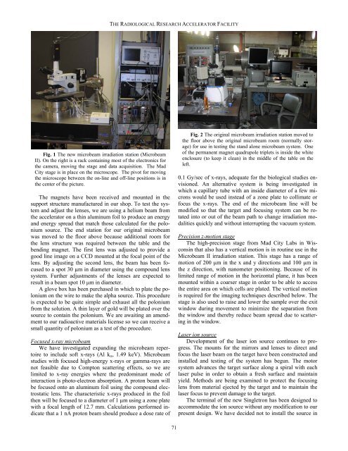
Fig. 1 The new microbeam irradiation station (Microbeam<br />
II). On the right is a rack containing most of the electronics for<br />
the camera, moving the stage and data acquisition. The Mad<br />
City stage is in place on the microscope. The pivot for moving<br />
the microscope between the on-line and off-line positions is in<br />
the center of the picture.<br />
The magnets have been received and mounted in the<br />
support structure manufactured in our shop. To test the system<br />
and adjust the lenses, we are using a helium beam from<br />
the accelerator on a thin aluminum foil to produce an energy<br />
and energy spread that match those calculated for the polonium<br />
source. The end station for our original microbeam<br />
was moved to the floor above because additional room for<br />
the lens structure was required between the table and the<br />
bending magnet. The first lens was adjusted to provide a<br />
good line image on a CCD mounted at the focal point of the<br />
lens. By adjusting the second lens, the beam has been focused<br />
to a spot 30 µm in diameter using the compound lens<br />
system. Further adjustments of the lenses are expected to<br />
result in a beam spot 10 µm in diameter.<br />
A glove box has been purchased in which to plate the polonium<br />
on the wire to make the alpha source. This procedure<br />
is expected to be quite simple and exhaust all the polonium<br />
from the solution. A thin layer of gold will be plated over the<br />
source to contain the polonium. We are awaiting an amendment<br />
to our radioactive materials license so we can receive a<br />
small quantity of polonium as a test of the procedure.<br />
Focused x-ray microbeam<br />
We have investigated expanding the microbeam repertoire<br />
to include soft x-rays (Al k α , 1.49 keV). Microbeam<br />
studies with focused high-energy x-rays or gamma-rays are<br />
not feasible due to Compton scattering effects, so we are<br />
limited to x-ray energies where the predominant mode of<br />
interaction is photo-electron absorption. A proton beam will<br />
be focused onto an aluminum foil using the compound electrostatic<br />
lens. The characteristic x-rays produced in the foil<br />
then will be focused to a diameter of 1 µm using a zone plate<br />
with a focal length of 12.7 mm. Calculations performed indicate<br />
that a 1 nA proton beam should produce a dose rate of<br />
Fig. 2 The original microbeam irradiation station moved to<br />
the floor above the original microbeam room (normally storage)<br />
for use in testing the stand alone microbeam system. One<br />
of the permanent magnet quadrupole triplets is inside the white<br />
enclosure (to keep it clean) in the middle of the table on the<br />
left.<br />
0.1 Gy/sec of x-rays, adequate for the biological studies envisioned.<br />
An alternative system is being investigated in<br />
which a capillary tube with an inside diameter of a few microns<br />
would be used instead of a zone plate to collimate or<br />
focus the x-rays. The end of the microbeam line will be<br />
modified so that the target and focusing system can be rotated<br />
into or out of the beam path to change irradiation modalities<br />
quickly and without interrupting the vacuum system.<br />
Precision z-motion stage<br />
The high-precision stage from Mad City Labs in Wisconsin<br />
that also has a vertical motion is in routine use in the<br />
Microbeam II irradiation station. This stage has a range of<br />
motion of 200 µm in the x and y directions and 100 µm in<br />
the z direction, with nanometer positioning. Because of its<br />
limited range of motion in the horizontal plane, it has been<br />
mounted within a coarser stage in order to be able to access<br />
the entire area on which cells are plated. The vertical motion<br />
is required for the imaging techniques described below. The<br />
stage is also used to raise and lower the sample over the exit<br />
window during movement to minimize the separation from<br />
the window and thereby reduce beam spread due to scattering<br />
in the window.<br />
Laser ion source<br />
Development of the laser ion source continues to progress.<br />
The mounts for the mirrors and lenses to direct and<br />
focus the laser beam on the target have been constructed and<br />
installed and testing of the system has begun. The motor<br />
system advances the target surface along a spiral with each<br />
laser pulse in order to obtain a fresh surface and maintain<br />
yield. Methods are being examined to protect the focusing<br />
lens from material ejected by the target and to maintain the<br />
laser focus to prevent damage to the target.<br />
The terminal of the new Singletron has been designed to<br />
accommodate the ion source without any modification to our<br />
present design. We have decided not to install the source in<br />
71