

BD Turbo Guard / Blow-Off Valve Installation Manual - BD Power
BD Turbo Guard / Blow-Off Valve Installation Manual - BD Power
BD Turbo Guard / Blow-Off Valve Installation Manual - BD Power

You also want an ePaper? Increase the reach of your titles
YUMPU automatically turns print PDFs into web optimized ePapers that Google loves.
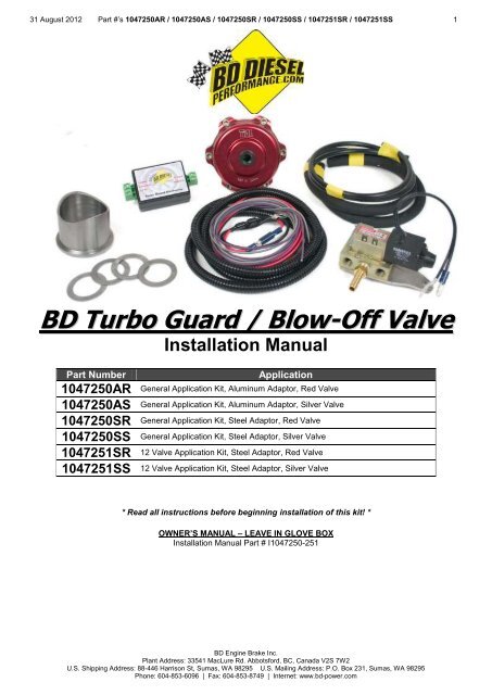
31 August 2012 Part #’s 1047250AR / 1047250AS / 1047250SR / 1047250SS / 1047251SR / 1047251SS 1<br />
<strong>BD</strong> <strong>Turbo</strong> <strong>Guard</strong> / <strong>Blow</strong>-<strong>Off</strong> <strong>Valve</strong><br />
<strong>Installation</strong> <strong>Manual</strong><br />
Part Number<br />
Application<br />
1047250AR General Application Kit, Aluminum Adaptor, Red <strong>Valve</strong><br />
1047250AS General Application Kit, Aluminum Adaptor, Silver <strong>Valve</strong><br />
1047250SR General Application Kit, Steel Adaptor, Red <strong>Valve</strong><br />
1047250SS General Application Kit, Steel Adaptor, Silver <strong>Valve</strong><br />
1047251SR 12 <strong>Valve</strong> Application Kit, Steel Adaptor, Red <strong>Valve</strong><br />
1047251SS 12 <strong>Valve</strong> Application Kit, Steel Adaptor, Silver <strong>Valve</strong><br />
* Read all instructions before beginning installation of this kit! *<br />
OWNER’S MANUAL – LEAVE IN GLOVE BOX<br />
<strong>Installation</strong> <strong>Manual</strong> Part # I1047250-251<br />
<strong>BD</strong> Engine Brake Inc.<br />
Plant Address: 33541 MacLure Rd. Abbotsford, BC, Canada V2S 7W2<br />
U.S. Shipping Address: 88-446 Harrison St, Sumas, WA 98295 U.S. Mailing Address: P.O. Box 231, Sumas, WA 98295<br />
Phone: 604-853-6096 | Fax: 604-853-8749 | Internet: www.bd-power.com
31 August 2012 Part #’s 1047250AR / 1047250AS / 1047250SR / 1047250SS / 1047251SR / 1047251SS 2<br />
TABLE OF CONTENTS<br />
Welcome ................................................................................................................... 3<br />
Special Tools Required ............................................................................................. 3<br />
Pre-<strong>Installation</strong> .......................................................................................................... 4<br />
Dodge 12/24V Auto Trans Install .............................................................................. 4<br />
Intercooler Tube Removal ......................................................................................... 6<br />
Intercooler Tube <strong>Installation</strong> ...................................................................................... 8<br />
Spool <strong>Valve</strong> <strong>Installation</strong> ............................................................................................. 9<br />
Dodge 12V <strong>Manual</strong> Trans Install ............................................................................. 11<br />
Throttle Switch ............................................................................................... 11<br />
Wiring & Plumbing Diagram ........................................................................... 14<br />
Wiring & Plumbing Diagram ........................................................................... 15<br />
Duramax Install (2001- 2004).................................................................................. 16<br />
Wiring And Plumbing Diagram ....................................................................... 18<br />
Duramax Install LLY,LBZ,LMM (2004.5- ................................................................. 19<br />
Wiring And Plumbing Diagram ....................................................................... 20<br />
Ford 7.3/ 6.0L (R/S) <strong>Installation</strong> .............................................................................. 21<br />
Wiring And Plumbing Diagram ....................................................................... 23<br />
Ford <strong>Power</strong>stroke 6.4.............................................................................................. 24<br />
Wiring And Plumbing Diagram ....................................................................... 26<br />
TGE Adjustment & Testing ..................................................................................... 27<br />
Troubleshooting ...................................................................................................... 30<br />
OPERATING GUIDELINES .................................................................................... 30<br />
<strong>BD</strong> Engine Brake Inc.<br />
Plant Address: 33541 MacLure Rd. Abbotsford, BC, Canada V2S 7W2<br />
U.S. Shipping Address: 88-446 Harrison St, Sumas, WA 98295 U.S. Mailing Address: P.O. Box 231, Sumas, WA 98295<br />
Phone: 604-853-6096 | Fax: 604-853-8749 | Internet: www.bd-power.com
31 August 2012 Part #’s 1047250AR / 1047250AS / 1047250SR / 1047250SS / 1047251SR / 1047251SS 3<br />
Welcome<br />
Thank you for purchasing a <strong>BD</strong> <strong>Turbo</strong> <strong>Guard</strong> kit. This manual is divided into<br />
different areas to assist you with your installation of the different kits and operation<br />
of the <strong>Turbo</strong> <strong>Guard</strong>.<br />
The <strong>BD</strong> <strong>Turbo</strong> <strong>Guard</strong> is one of the nicest units on the market. The body and all<br />
internal components are CNC machined from 6061 aluminum alloys. It features the<br />
one of the largest dump valves at a whopping 1.98” (50.5 mm), which gives you the<br />
highest flow in the industry. A V-Band clamping system allows easy installation and<br />
removal.<br />
The valve seal utilizes a Viton O-ring that is clamped in place to prevent the<br />
possibility of sticking to the seat and pulling out. The valve stem and guide are<br />
Teflon lubricated and hard anodize coated for wear resistance.<br />
Special Tools Required<br />
Drill with 1 7/8” hole saw<br />
Crimping Pliers<br />
Test light<br />
¼” Drive Socket set<br />
Small Blade tip screwdriver<br />
MIG or TIG Welder (Aluminum feed for the Duramax kit)<br />
Teflon tape or putty<br />
5/32” Allen key<br />
<strong>BD</strong> Engine Brake Inc.<br />
Plant Address: 33541 MacLure Rd. Abbotsford, BC, Canada V2S 7W2<br />
U.S. Shipping Address: 88-446 Harrison St, Sumas, WA 98295 U.S. Mailing Address: P.O. Box 231, Sumas, WA 98295<br />
Phone: 604-853-6096 | Fax: 604-853-8749 | Internet: www.bd-power.com
31 August 2012 Part #’s 1047250AR / 1047250AS / 1047250SR / 1047250SS / 1047251SR / 1047251SS 4<br />
Pre-<strong>Installation</strong><br />
** PLEASE READ THIS MANUAL COMPLETELY BEFORE<br />
INSTALLING THE BLOW-OFF VALVE **<br />
To prevent damage to electronic components, it is recommended that you<br />
disconnect both negative battery terminals before starting.<br />
Dodge 12/24V Auto Trans Install<br />
This kit is designed for the Dodge Cummins 12 or 24 <strong>Valve</strong> with an APPS/TPS<br />
voltage source. You will be using the new <strong>Turbo</strong> <strong>Guard</strong> Electronics (TGE) module<br />
to determine when to activate the valve. It is recommended that you mount this<br />
module underneath the steering column inside the cab to keep out any moisture or<br />
dirt from under the hood.<br />
Locate a switched 12 Volt power source in the fuse panel with a test light. You can<br />
also use the supplied fuse tap and flag connector for another power source as well.<br />
<strong>BD</strong> Engine Brake Inc.<br />
Plant Address: 33541 MacLure Rd. Abbotsford, BC, Canada V2S 7W2<br />
U.S. Shipping Address: 88-446 Harrison St, Sumas, WA 98295 U.S. Mailing Address: P.O. Box 231, Sumas, WA 98295<br />
Phone: 604-853-6096 | Fax: 604-853-8749 | Internet: www.bd-power.com
31 August 2012 Part #’s 1047250AR / 1047250AS / 1047250SR / 1047250SS / 1047251SR / 1047251SS 5<br />
This 12 volt switched power should go to the “Switched <strong>Power</strong>” input on the TGE<br />
module using the supplied red wire.<br />
You will need to use a set of crimping pliers to connect the connectors on the power<br />
side of the red wire.<br />
When connecting the power wire to the TGE, there are special quick<br />
connectors that allow an easy installation. Trim the proper amount of<br />
insulation off of the wire and be sure to tighten the locking screw on the green<br />
quick connector. Be careful that there are no cross shorts between cables.<br />
Also check to make sure that the green connection block is firmly inserted<br />
into the TGE case.<br />
You also need to locate a clean ground location which should be wired into the<br />
“Ground” input on the TGE module using the supplied black wire and ring<br />
connector. Usually a bolt will protrude from the firewall, which makes a good<br />
ground. Please again trim excess wire.<br />
Route the gray and violet wires through the firewall and into the engine<br />
compartment. The violet wire should be connected to the TGE input labeled<br />
“APPS” and the grey wire should be wired into the TGE output labeled “Output”.<br />
Location Year Wire Color<br />
2004-05 Brown w/ White Tracer<br />
APPS/TPS Sensor<br />
2003 Yellow<br />
Or at ECM<br />
1994-2002 Light Blue w/ Black Tracer<br />
PCM 1994-2003+ Orange w/ Dark Blue Tracer<br />
The violet wire from the <strong>Turbo</strong> <strong>Guard</strong> kit should be connected to the APPS signal.<br />
Reference to the chart above for which wire to tap onto. This signal is located at the<br />
driver’s side front of the Cummins 24 valve engine above the injection pump on<br />
vehicles 98-03. On the 2004+ vehicles this wire will be located at APPS sensor on<br />
the throttle pedal.<br />
Use the supplied Posi-Tap to tap into the wire. Note that you may also tap into<br />
this wire at the PCM and as well at the Cummins ECM. This wire should range from<br />
approximately 0.5 volts to 5 volts depending on how far the pedal is depressed. At<br />
idle the voltage should be near the 0.5 to 1.0 volt scale and at full throttle it should<br />
read close to 3-5 volts.<br />
On 12 <strong>Valve</strong> engines the APPS/TPS is at the rear of the P7100 injection pump.<br />
Use the supplied Posi-Tap to tap into this wire and connect it to the violet wire. You<br />
may have to trim the excess wire.<br />
<strong>BD</strong> Engine Brake Inc.<br />
Plant Address: 33541 MacLure Rd. Abbotsford, BC, Canada V2S 7W2<br />
U.S. Shipping Address: 88-446 Harrison St, Sumas, WA 98295 U.S. Mailing Address: P.O. Box 231, Sumas, WA 98295<br />
Phone: 604-853-6096 | Fax: 604-853-8749 | Internet: www.bd-power.com
31 August 2012 Part #’s 1047250AR / 1047250AS / 1047250SR / 1047250SS / 1047251SR / 1047251SS 6<br />
Once the Violet APPS wire has been routed connect the Grey wire to the bullet<br />
connector on the spool valve that you mounted to the intake horn earlier. You will<br />
need crimping pliers to attach the opposite gender bullet connector to the grey wire.<br />
Route the wire inside of the supplied loom. Please be careful of routing the wires<br />
away from any heat sources or any moving parts.<br />
Intercooler Tube Removal<br />
Before welding the <strong>Blow</strong>-<strong>Off</strong> <strong>Valve</strong><br />
adapter onto the cool side of the<br />
intercooler tube (driver side), you<br />
must remove it.<br />
Remove the two clamps located<br />
on the intercooler boots. Use a<br />
7/16” deep socket to remove the<br />
top and bottom boot clamp.<br />
The adapter will be installed on<br />
the upper portion of the tube<br />
furthest away from the intercooler.<br />
Using a tape measure, measure<br />
about 2½ - 3” from the upper edge<br />
of the tube and mark a drill spot. This mark should be the center of the adapter.<br />
As you can see from the picture above, the edge of the adapter should be within a<br />
½ inch from the second raised lip. Once you have marked your drill location, use a<br />
center punch and drill a pilot hole. Use a 1-7/8” hole saw and drill out the remainder<br />
of the hole.<br />
Place the adapter and the tube in<br />
a vice in order to hold the adapter<br />
tight against the tube while<br />
welding. You can tack-weld the<br />
adapter if you are unsure of its<br />
proper location. After the weld is<br />
complete, be absolutely certain<br />
that the weld is strong and there<br />
are no air leaks.<br />
Warning: Ensure the weld is<br />
clean on the inside of the tube.<br />
If any slag is left there is a<br />
chance of engine damage.<br />
<strong>BD</strong> Engine Brake Inc.<br />
Plant Address: 33541 MacLure Rd. Abbotsford, BC, Canada V2S 7W2<br />
U.S. Shipping Address: 88-446 Harrison St, Sumas, WA 98295 U.S. Mailing Address: P.O. Box 231, Sumas, WA 98295<br />
Phone: 604-853-6096 | Fax: 604-853-8749 | Internet: www.bd-power.com
31 August 2012 Part #’s 1047250AR / 1047250AS / 1047250SR / 1047250SS / 1047251SR / 1047251SS 7<br />
After the weld has been cleaned, a nice coat of black paint is recommended to<br />
eliminate any tarnishing.<br />
<strong>BD</strong> Engine Brake Inc.<br />
Plant Address: 33541 MacLure Rd. Abbotsford, BC, Canada V2S 7W2<br />
U.S. Shipping Address: 88-446 Harrison St, Sumas, WA 98295 U.S. Mailing Address: P.O. Box 231, Sumas, WA 98295<br />
Phone: 604-853-6096 | Fax: 604-853-8749 | Internet: www.bd-power.com
31 August 2012 Part #’s 1047250AR / 1047250AS / 1047250SR / 1047250SS / 1047251SR / 1047251SS 8<br />
Intercooler Tube <strong>Installation</strong><br />
Use the supplied aluminum V band clamp to attach the<br />
<strong>Blow</strong>-<strong>Off</strong> <strong>Valve</strong> to the newly welded adapter. Do not forget<br />
to use the supplied Viton O-ring to seal the valve to the<br />
adapter.<br />
Be very careful not to over-extend the V band clamp, as<br />
damage will result.<br />
Tighten the Allen bolt with a 5/32” Allen key so that the<br />
valve is securely fastened to<br />
the adapter.<br />
Re-install the intercooler tube<br />
in the reverse order that it<br />
was removed.<br />
Be sure that all the<br />
intercooler boot clamps are<br />
securely tightened. Rotate<br />
the tube so that the <strong>Blow</strong>-<strong>Off</strong><br />
<strong>Valve</strong> is facing towards the<br />
front the truck.<br />
<strong>BD</strong> Engine Brake Inc.<br />
Plant Address: 33541 MacLure Rd. Abbotsford, BC, Canada V2S 7W2<br />
U.S. Shipping Address: 88-446 Harrison St, Sumas, WA 98295 U.S. Mailing Address: P.O. Box 231, Sumas, WA 98295<br />
Phone: 604-853-6096 | Fax: 604-853-8749 | Internet: www.bd-power.com
31 August 2012 Part #’s 1047250AR / 1047250AS / 1047250SR / 1047250SS / 1047251SR / 1047251SS 9<br />
<strong>Turbo</strong> <strong>Blow</strong>-off <strong>Valve</strong> installed in intercooler tube<br />
Spool <strong>Valve</strong> <strong>Installation</strong><br />
Remove the bolt holding the intake horn using a 10mm socket. Install the spool<br />
valve assembly ensuring the valve connections are the same as in the picture.<br />
Diode Assembly<br />
Ground<br />
Hollow Manifold<br />
Bolt<br />
<strong>BD</strong> Engine Brake Inc.<br />
Plant Address: 33541 MacLure Rd. Abbotsford, BC, Canada V2S 7W2<br />
U.S. Shipping Address: 88-446 Harrison St, Sumas, WA 98295 U.S. Mailing Address: P.O. Box 231, Sumas, WA 98295<br />
Phone: 604-853-6096 | Fax: 604-853-8749 | Internet: www.bd-power.com
31 August 2012 Part #’s 1047250AR / 1047250AS / 1047250SR / 1047250SS / 1047251SR / 1047251SS 10<br />
When securing the spool valve assembly with the long 10mm bolt, connect the<br />
spool valve ground (ring connector) between the intake horn and the spool valve<br />
assembly. Be sure to re-torque the 10mm bolt, or a boost leak may occur. Install<br />
the “Free Wheeling” Diode pigtail assembly. Route the power through the red wire<br />
and then into the spool valve. The black wire of the assembly should be mounted to<br />
ground using the ring connector.<br />
Use the rubber hose to connect the <strong>Blow</strong>-<strong>Off</strong> <strong>Valve</strong> to the brass push-on connector<br />
on the spool valve. Secure the connection using the supplied hose clamps at each<br />
connection point. Keep the hoses as short as possible.<br />
Remove the 10mm bolt that holds the intake manifold plate in place. Install the<br />
supplied hollow manifold bolt with the blue or green “quick-connect” connector in<br />
place.<br />
It is recommended that a small amount of sealing putty be used on the manifold<br />
bolt. Route the hard plastic tube from the manifold connector to the blue or green<br />
“quick-connect” connector in the spool valve.<br />
Please verify the following connection points as each connection is numbered in the<br />
picture.<br />
Conn. Description<br />
1<br />
Engine Boost<br />
Pressure via<br />
“quick-connect”<br />
connector.<br />
2 N/C<br />
3 N/C<br />
4<br />
<strong>Blow</strong>-<strong>Off</strong> <strong>Valve</strong><br />
via rubber air<br />
hose<br />
5 N/C<br />
<strong>BD</strong> Engine Brake Inc.<br />
Plant Address: 33541 MacLure Rd. Abbotsford, BC, Canada V2S 7W2<br />
U.S. Shipping Address: 88-446 Harrison St, Sumas, WA 98295 U.S. Mailing Address: P.O. Box 231, Sumas, WA 98295<br />
Phone: 604-853-6096 | Fax: 604-853-8749 | Internet: www.bd-power.com
31 August 2012 Part #’s 1047250AR / 1047250AS / 1047250SR / 1047250SS / 1047251SR / 1047251SS 11<br />
If you are unsure about any connection, look through the next couple of pages and<br />
find your kit number. In your kit’s section you will find a wiring schematic that will<br />
assist your installation.<br />
Tighten the banjo bolt on top of the <strong>Blow</strong>-<strong>Off</strong> <strong>Valve</strong> securing the hose connection.<br />
You may also notice some pre-wired circuits connecting the ground to the power<br />
side of the spool valve. There should be a short diode harness wired as well. This<br />
is to remove any inductive spikes caused by the spool valve.<br />
Please trim any excess tubing or hose, trying to make the installation clean as<br />
possible.<br />
You will also notice that you received 4 shims in the kit as well. These shims are<br />
used to adjust the valve opening and closing pressure. The more shims you use,<br />
the higher the opening pressure.<br />
Dodge 12V <strong>Manual</strong> Trans Install<br />
This kit is designed for the Dodge Cummins 12 <strong>Valve</strong> with a standard transmission.<br />
A throttle pedal micro-switch is required for this application due to the fact that there<br />
is no TPS voltage. The purpose of this throttle switch is to indicate when then<br />
throttle is at the idle position.<br />
Throttle Switch<br />
At the throttle pedal, locate the nuts on the large aluminum bracket, just up from<br />
and to the left of the pedal. These nuts secure the aluminum bracket to the firewall<br />
and are the mount for the throttle and brake pedal. Remove the lower nut and<br />
loosen off the top nut. In the kit you will find the long throttle switch bracket, which<br />
has two long slots for the throttle switch.<br />
Slide the top end of the bracket (with the cut out slot) under the loosened upper nut<br />
and lay against the aluminum bracket so the stud that was exposed when you<br />
<strong>BD</strong> Engine Brake Inc.<br />
Plant Address: 33541 MacLure Rd. Abbotsford, BC, Canada V2S 7W2<br />
U.S. Shipping Address: 88-446 Harrison St, Sumas, WA 98295 U.S. Mailing Address: P.O. Box 231, Sumas, WA 98295<br />
Phone: 604-853-6096 | Fax: 604-853-8749 | Internet: www.bd-power.com
31 August 2012 Part #’s 1047250AR / 1047250AS / 1047250SR / 1047250SS / 1047251SR / 1047251SS 12<br />
removed the lower nut protrudes through the other slot on the Throttle Switch<br />
Bracket.<br />
Screw the lower nut<br />
back onto the stud, but<br />
do not tighten the nuts<br />
yet. In the kit, find the<br />
small 2-3/8” long<br />
bracket with two holes.<br />
The arm of the throttle<br />
pedal starts off wide,<br />
then angles off into a<br />
thinner section further<br />
up the pedal.<br />
Just before the pedals<br />
arm angles to the<br />
thinner section, place<br />
the middle hole of the<br />
bracket on the still wide<br />
section, close to the<br />
edge and angle the<br />
bracket towards the throttle switch on the other bracket you installed above.<br />
Ensure sufficient clearance between the long throttle switch bracket and throttle<br />
pedal by sliding the bracket as far to the left as possible, to eliminate any possibility<br />
of the pedal catching on the bracket.<br />
Adjust both brackets so that the small bracket you are holding on the pedal arm is<br />
going to make good contact with the throttle switch when the pedal is in its<br />
resting/idle position.<br />
Mark and drill the two holes on the pedal arm and screw or pop rivet the small<br />
bracket to the arm. Tighten the nuts for the aluminum bracket and make any<br />
necessary final adjustments to the throttle switch bracket on the aluminum bracket.<br />
Make sure the screws supporting the throttle switch and screws for the electrical<br />
wires on the switch are tight. Periodic adjustment of the throttle switch might be<br />
required to maintain proper contact with the bracket on the throttle pedal.<br />
Use the supplied line tapper or fuse tapper and find a 12v fused ignition switch<br />
power source and attach one side of the throttle pedal micro switch to the power<br />
source using the supplied red wire.<br />
Attach the long grey wire to the last connection on the throttle pedal micro switch<br />
and route the wire through the firewall. Continue to route the wire in a discrete<br />
<strong>BD</strong> Engine Brake Inc.<br />
Plant Address: 33541 MacLure Rd. Abbotsford, BC, Canada V2S 7W2<br />
U.S. Shipping Address: 88-446 Harrison St, Sumas, WA 98295 U.S. Mailing Address: P.O. Box 231, Sumas, WA 98295<br />
Phone: 604-853-6096 | Fax: 604-853-8749 | Internet: www.bd-power.com
31 August 2012 Part #’s 1047250AR / 1047250AS / 1047250SR / 1047250SS / 1047251SR / 1047251SS 13<br />
fashion to the bullet connector on the spool valve that you installed earlier on the<br />
intake horn of the engine.<br />
You will have to use a crimping tool to connect the bullet connector to the grey wire.<br />
Be conscious of moving or hot engine parts when routing the wire. Once all of the<br />
connections have been finalized and you are confident that everything is correct you<br />
may test all the connections. Turn the key to the “ON” position (KOEO).<br />
Press the throttle pedal up and down. As the accelerator pedal is applied, the spool<br />
valve should deactivate. A small click should be heard as the pedal is released and<br />
the spool valve should activate once again.<br />
You can test the circuit with a voltmeter or a test light. You must remember that<br />
when the key is “ON” and the throttle pedal is at an idle state the spool valve will be<br />
energized. As soon as the throttle is slightly pressed past idle position, the spool<br />
valve will deactivate. Refer to the diagram on the next page.<br />
<strong>BD</strong> Engine Brake Inc.<br />
Plant Address: 33541 MacLure Rd. Abbotsford, BC, Canada V2S 7W2<br />
U.S. Shipping Address: 88-446 Harrison St, Sumas, WA 98295 U.S. Mailing Address: P.O. Box 231, Sumas, WA 98295<br />
Phone: 604-853-6096 | Fax: 604-853-8749 | Internet: www.bd-power.com
31 August 2012 Part #’s 1047250AR / 1047250AS / 1047250SR / 1047250SS / 1047251SR / 1047251SS 14<br />
Wiring & Plumbing Diagram<br />
Turn to page 20 to continue with the <strong>Turbo</strong> <strong>Guard</strong> installation.<br />
<strong>BD</strong> Engine Brake Inc.<br />
Plant Address: 33541 MacLure Rd. Abbotsford, BC, Canada V2S 7W2<br />
U.S. Shipping Address: 88-446 Harrison St, Sumas, WA 98295 U.S. Mailing Address: P.O. Box 231, Sumas, WA 98295<br />
Phone: 604-853-6096 | Fax: 604-853-8749 | Internet: www.bd-power.com
31 August 2012 Part #’s 1047250AR / 1047250AS / 1047250SR / 1047250SS / 1047251SR / 1047251SS 15<br />
Wiring & Plumbing Diagram<br />
Turn to page 20 to continue with the <strong>Turbo</strong> <strong>Guard</strong> installation.<br />
<strong>BD</strong> Engine Brake Inc.<br />
Plant Address: 33541 MacLure Rd. Abbotsford, BC, Canada V2S 7W2<br />
U.S. Shipping Address: 88-446 Harrison St, Sumas, WA 98295 U.S. Mailing Address: P.O. Box 231, Sumas, WA 98295<br />
Phone: 604-853-6096 | Fax: 604-853-8749 | Internet: www.bd-power.com
31 August 2012 Part #’s 1047250AR / 1047250AS / 1047250SR / 1047250SS / 1047251SR / 1047251SS 16<br />
Duramax Install (2001- 2004)<br />
The installation of the turbo guard for the Duramax is slightly different as the other<br />
applications although the concept is still the same. It is highly recommended that<br />
you read over the Dodge installation portion of this manual.<br />
The intercooler tubes that you will be mounting the blow-off valve adapter to are<br />
made of aluminum; hence you will need an aluminum welder to mount the aluminum<br />
adapter. The intercooler tube of choice is the turbocharger compressor outlet tube,<br />
which is located on the driver side. If you cannot mount it there, then the passenger<br />
side engine inlet will do, although you may suffer some response time.<br />
You will need to use the brass three-way adapter to tap into the wastegate line as a<br />
boost source. The APPS/TPS wire that you are looking for is Dark Blue - it can be<br />
found on the accelerator pedal assembly inside the truck.<br />
A suggested location for the spool valve is on the trucks firewall over top of the<br />
engine ground strap. Remember to keep the plastic & rubber hoses as short as<br />
possible.<br />
Use a ground strap<br />
bolt to mount the<br />
spool valve.<br />
Use a wastegate<br />
line as a boost<br />
source.<br />
Mount the valve on the<br />
compressor outlet of<br />
the intercooler tube<br />
(before the<br />
intercooler)<br />
<strong>BD</strong> Engine Brake Inc.<br />
Plant Address: 33541 MacLure Rd. Abbotsford, BC, Canada V2S 7W2<br />
U.S. Shipping Address: 88-446 Harrison St, Sumas, WA 98295 U.S. Mailing Address: P.O. Box 231, Sumas, WA 98295<br />
Phone: 604-853-6096 | Fax: 604-853-8749 | Internet: www.bd-power.com
31 August 2012 Part #’s 1047250AR / 1047250AS / 1047250SR / 1047250SS / 1047251SR / 1047251SS 17<br />
Secondary mounting<br />
location. When using<br />
this location you will<br />
need to find a<br />
mounting bolt for the<br />
spool valve.<br />
You will also notice that you received 4 shims in the kit as well. These shims are<br />
used to adjust the valve opening pressure. The more shims you use the higher the<br />
opening pressure.<br />
<strong>BD</strong> Engine Brake Inc.<br />
Plant Address: 33541 MacLure Rd. Abbotsford, BC, Canada V2S 7W2<br />
U.S. Shipping Address: 88-446 Harrison St, Sumas, WA 98295 U.S. Mailing Address: P.O. Box 231, Sumas, WA 98295<br />
Phone: 604-853-6096 | Fax: 604-853-8749 | Internet: www.bd-power.com
31 August 2012 Part #’s 1047250AR / 1047250AS / 1047250SR / 1047250SS / 1047251SR / 1047251SS 18<br />
Wiring And Plumbing Diagram<br />
<strong>BD</strong> Engine Brake Inc.<br />
Plant Address: 33541 MacLure Rd. Abbotsford, BC, Canada V2S 7W2<br />
U.S. Shipping Address: 88-446 Harrison St, Sumas, WA 98295 U.S. Mailing Address: P.O. Box 231, Sumas, WA 98295<br />
Phone: 604-853-6096 | Fax: 604-853-8749 | Internet: www.bd-power.com
31 August 2012 Part #’s 1047250AR / 1047250AS / 1047250SR / 1047250SS / 1047251SR / 1047251SS 19<br />
Duramax Install LLY,LBZ,LMM (2004.5-<br />
Being that you have a VGT turbocharger you will not be able to pull boost pressure<br />
from the turbocharger waste gate line. Ideally it is best to install the unit on the<br />
turbocharger outlet tube (driver’s side). For the LLY you may have no choice but to<br />
install the unit into engine inlet pipe (passenger’s side). In the case of the LBZ and<br />
LMM you don’t have a choice and must install the unit on the turbocharger outlet<br />
pipe (driver’s side).<br />
Also it is very important that the boost pressure source for the top of the BOV be<br />
from the turbocharger outlet side.<br />
To install the boost pressure source there should be a nutsert included with the kit.<br />
You will need to remove the turbocharger outlet pipe and install the nutsert in it.<br />
Once this pipe is removed, drill a 3/8” hole on the top of the pipe closest to the<br />
turbo. Use a file or de-burring wheel to clean to hole. Coat the nutsert with a<br />
moderate temperature silicon or gasket maker. Insert the coated nutsert into the<br />
3/8” hole in the pipe. Insert the Allen head screw through the install nut with the<br />
serrated end facing towards the nutsert. Use a wrench to hold the nut in place while<br />
tightening the Allen screw with the provided Allen key. Continue to tighten the Allen<br />
key until the force needed to turn it drastically increases. Reinstall the tube into<br />
place on the truck, making sure the all the intercooler boots are clean of oil and the<br />
clamps are tight. Route the black nylon house over to the switch valve.<br />
<strong>BD</strong> Engine Brake Inc.<br />
Plant Address: 33541 MacLure Rd. Abbotsford, BC, Canada V2S 7W2<br />
U.S. Shipping Address: 88-446 Harrison St, Sumas, WA 98295 U.S. Mailing Address: P.O. Box 231, Sumas, WA 98295<br />
Phone: 604-853-6096 | Fax: 604-853-8749 | Internet: www.bd-power.com
31 August 2012 Part #’s 1047250AR / 1047250AS / 1047250SR / 1047250SS / 1047251SR / 1047251SS 20<br />
Wiring And Plumbing Diagram<br />
<strong>BD</strong> Engine Brake Inc.<br />
Plant Address: 33541 MacLure Rd. Abbotsford, BC, Canada V2S 7W2<br />
U.S. Shipping Address: 88-446 Harrison St, Sumas, WA 98295 U.S. Mailing Address: P.O. Box 231, Sumas, WA 98295<br />
Phone: 604-853-6096 | Fax: 604-853-8749 | Internet: www.bd-power.com
31 August 2012 Part #’s 1047250AR / 1047250AS / 1047250SR / 1047250SS / 1047251SR / 1047251SS 21<br />
Ford 7.3/ 6.0L (R/S) <strong>Installation</strong><br />
The installation of the turbo guard for the Ford is slightly different as the other<br />
‘T’ into boost sensor line<br />
Mount valve in this location.<br />
applications although the concept is still the same. It is highly recommended that<br />
you read over the Dodge installation portion of this manual.<br />
Although the installation pictures show a 6.0L the concept is still the same for the<br />
7.3L.<br />
The intercooler tubes that you will be mounting the blow-off valve adapter to are<br />
made of steel; ideally a TIG welder looks the nicest but a MIG welder will do. The<br />
intercooler tube of choice is the turbocharger compressor outlet tube, which is<br />
located on the driver side (7.3L) and on the passenger side (6.0L). If you cannot<br />
mount it there, then the opposite side (engine inlet) will do, although you may suffer<br />
some response time.<br />
You will need to use the brass three-way adapter to tap into the boost sensor line as<br />
a boost source. The APPS/TPS wire that you are looking for is mounted inside the<br />
cab just off the pedal. Use the table to locate the proper color wire.<br />
<strong>BD</strong> Engine Brake Inc.<br />
Plant Address: 33541 MacLure Rd. Abbotsford, BC, Canada V2S 7W2<br />
U.S. Shipping Address: 88-446 Harrison St, Sumas, WA 98295 U.S. Mailing Address: P.O. Box 231, Sumas, WA 98295<br />
Phone: 604-853-6096 | Fax: 604-853-8749 | Internet: www.bd-power.com
31 August 2012 Part #’s 1047250AR / 1047250AS / 1047250SR / 1047250SS / 1047251SR / 1047251SS 22<br />
Vehicle Year APPS/TPS Wire Color<br />
1999.5-02 7.3L Grey w/White<br />
2003-04 6.0L Yellow w/White<br />
2005-07 6.0L White w/Red<br />
A suggested location for the spool valve is on the trucks firewall. Remember to<br />
keep the plastic & rubber hoses as short as possible and away from any heat<br />
source.<br />
You will also notice that you received 4 shims in the kit as well. These shims are<br />
used to adjust the valve opening pressure. The more shims you use the higher the<br />
opening pressure.<br />
<strong>BD</strong> Engine Brake Inc.<br />
Plant Address: 33541 MacLure Rd. Abbotsford, BC, Canada V2S 7W2<br />
U.S. Shipping Address: 88-446 Harrison St, Sumas, WA 98295 U.S. Mailing Address: P.O. Box 231, Sumas, WA 98295<br />
Phone: 604-853-6096 | Fax: 604-853-8749 | Internet: www.bd-power.com
31 August 2012 Part #’s 1047250AR / 1047250AS / 1047250SR / 1047250SS / 1047251SR / 1047251SS 23<br />
Wiring And Plumbing Diagram<br />
<strong>BD</strong> Engine Brake Inc.<br />
Plant Address: 33541 MacLure Rd. Abbotsford, BC, Canada V2S 7W2<br />
U.S. Shipping Address: 88-446 Harrison St, Sumas, WA 98295 U.S. Mailing Address: P.O. Box 231, Sumas, WA 98295<br />
Phone: 604-853-6096 | Fax: 604-853-8749 | Internet: www.bd-power.com
31 August 2012 Part #’s 1047250AR / 1047250AS / 1047250SR / 1047250SS / 1047251SR / 1047251SS 24<br />
Ford <strong>Power</strong>stroke 6.4<br />
Being that you have twin turbocharger’s, you will not be able to pull boost pressure<br />
from the turbocharger waste gate line. In your case you will need to pull the boost<br />
srouce from the turbocharger compressor outlet pipe located on the driver’s side.<br />
While the valve should be located on the manifold air intake side located on the<br />
passenger side.<br />
BOV Location<br />
Boost Source<br />
To install the boost pressure source there should be a nutsert included with the kit.<br />
You will need to remove the turbocharger outlet pipe and install the nutsert in it (You<br />
can install nutsert without removing the pipe but you will need to ensure that none of<br />
the drill debris is left in the pipe). Once this pipe is removed, drill a 3/8” hole on the<br />
top of the pipe closest to the turbo. Use a file or de-burring wheel to clean to hole.<br />
Coat the nutsert with a moderate temperature silicon or gasket maker. Insert the<br />
coated nutsert into the 3/8” hole in the pipe. Insert the Allen head screw through the<br />
install nut with the serrated end facing towards the nutsert. Use a wrench to hold the<br />
nut in place while tightening the Allen screw with the provided Allen key. Continue to<br />
tighten the Allen key until the force needed to turn it drastically increases. Reinstall<br />
the tube into place on the truck, making sure the all the intercooler boots are clean<br />
of oil and the clamps are tight. Route the black nylon house over to the switch<br />
valve.<br />
<strong>BD</strong> Engine Brake Inc.<br />
Plant Address: 33541 MacLure Rd. Abbotsford, BC, Canada V2S 7W2<br />
U.S. Shipping Address: 88-446 Harrison St, Sumas, WA 98295 U.S. Mailing Address: P.O. Box 231, Sumas, WA 98295<br />
Phone: 604-853-6096 | Fax: 604-853-8749 | Internet: www.bd-power.com
31 August 2012 Part #’s 1047250AR / 1047250AS / 1047250SR / 1047250SS / 1047251SR / 1047251SS 25<br />
<strong>BD</strong> Engine Brake Inc.<br />
Plant Address: 33541 MacLure Rd. Abbotsford, BC, Canada V2S 7W2<br />
U.S. Shipping Address: 88-446 Harrison St, Sumas, WA 98295 U.S. Mailing Address: P.O. Box 231, Sumas, WA 98295<br />
Phone: 604-853-6096 | Fax: 604-853-8749 | Internet: www.bd-power.com
31 August 2012 Part #’s 1047250AR / 1047250AS / 1047250SR / 1047250SS / 1047251SR / 1047251SS 26<br />
Wiring And Plumbing Diagram<br />
<strong>BD</strong> Engine Brake Inc.<br />
Plant Address: 33541 MacLure Rd. Abbotsford, BC, Canada V2S 7W2<br />
U.S. Shipping Address: 88-446 Harrison St, Sumas, WA 98295 U.S. Mailing Address: P.O. Box 231, Sumas, WA 98295<br />
Phone: 604-853-6096 | Fax: 604-853-8749 | Internet: www.bd-power.com
31 August 2012 Part #’s 1047250AR / 1047250AS / 1047250SR / 1047250SS / 1047251SR / 1047251SS 27<br />
TGE Adjustment & Testing<br />
The unit is abundant with features as it offers the user the most advanced custom<br />
functions available. The unit works by monitoring the APPS/TPS signals and<br />
quickly reacts to the decrease in voltage associated to a quick release of the<br />
throttle.<br />
To achieve the correct setting for the activation of the <strong>Blow</strong>-<strong>Off</strong> valve in relation to<br />
the throttle pedal, the TGE module must be calibrated for your vehicle. The<br />
adjustable settings are: APPS, TIME, RE-APPLY, PULSE, and CLUTCH CANCEL.<br />
The adjustment screws are accessed by removing the cover from the module. To<br />
remove the cover, trim away the center of the sticker on the top of the module so<br />
you can access the cover screw. Remove the screw & the cover will lift off. See<br />
photo on page 29.<br />
APPS<br />
This option allows the user to adjust the amount of voltage (APPS/TPS) that needs<br />
to be dropped before the valve will open and discharge boost. Turn the unit<br />
clockwise to increase the voltage or amount of throttle that has to be lifted. Turn the<br />
unit counter-clockwise to initiate a faster or quicker activation with less of a TPS<br />
drop.<br />
TIME<br />
This setting allows the user to adjust the period of time that the APPS/TPS setting<br />
must be initiated in to activate the valve. It controls the amount of time that the<br />
microprocessor monitors the APPS/TPS signal.<br />
If you would like to increase the time frame (Volts/Seconds) then you would turn the<br />
potentiometer in the clockwise direction. To decrease the scanning period, turn the<br />
potentiometer in the counter-clockwise direction. Increasing the scanning timing<br />
tends to slow down the response. Most likely you will only need to adjust this<br />
setting once; usually the factory default setting is fine.<br />
For example, a decrease of 0.5 Volts in 0.25 seconds would respond faster than a<br />
decrease of 0.5 Volts in 1 second.<br />
The next diagram is a simulation of the APPS/TPS voltage over time on what<br />
typically happens when the throttle is quickly released. You can see by adjusting<br />
the APPS/TPS sensitivity you can control when the valve activates based on the<br />
amount of voltage dropped. The TIME setting controls activation assuring the<br />
voltage drop occurred in the right period of time. This eliminates any valve<br />
activations that are not quick or fast.<br />
<strong>BD</strong> Engine Brake Inc.<br />
Plant Address: 33541 MacLure Rd. Abbotsford, BC, Canada V2S 7W2<br />
U.S. Shipping Address: 88-446 Harrison St, Sumas, WA 98295 U.S. Mailing Address: P.O. Box 231, Sumas, WA 98295<br />
Phone: 604-853-6096 | Fax: 604-853-8749 | Internet: www.bd-power.com
APPS (Voltage)<br />
This is adjusted by the APPS<br />
adjustment POT<br />
31 August 2012 Part #’s 1047250AR / 1047250AS / 1047250SR / 1047250SS / 1047251SR / 1047251SS 28<br />
This is adjusted by the TIME adjustment POT<br />
Time (Seconds)<br />
RE-APPLY<br />
This setting basically allows the user to adjust how much of a re-apply APPS/TPS<br />
voltage to allow before canceling the valve activation. If this setting were not<br />
present every time the throttle was re-applied while the valve was open you would<br />
be dumping boost. With this setting the user will cancel that valve activation when<br />
the throttle is pressed which allows for a faster transition and less wasted energy.<br />
The stock setting should be appropriate. Turn the potentiometer counter-clockwise<br />
for less APPS apply, and Clockwise for a more APPS apply.<br />
PULSE<br />
This is the length of time that the valve should be pulsed open for. Turn the<br />
potentiometer counter-clockwise for less time, and Clockwise for a longer pulse.<br />
CLUTCH CANCEL<br />
This option basically cancels any operation whenever 12 volts is applied to this<br />
input. If a user wanted they could hook a 12-volt switch up to this input to cancel<br />
the operations when shifting or if they wanted to turn the unit off. This option is not<br />
normally used.<br />
DEFAULT SETTINGS<br />
You’ll notice that there are small arrows on the dials of the potentiometers, in the<br />
graphic below these arrows have been emphasized to show the default settings.<br />
<strong>BD</strong> Engine Brake Inc.<br />
Plant Address: 33541 MacLure Rd. Abbotsford, BC, Canada V2S 7W2<br />
U.S. Shipping Address: 88-446 Harrison St, Sumas, WA 98295 U.S. Mailing Address: P.O. Box 231, Sumas, WA 98295<br />
Phone: 604-853-6096 | Fax: 604-853-8749 | Internet: www.bd-power.com
31 August 2012 Part #’s 1047250AR / 1047250AS / 1047250SR / 1047250SS / 1047251SR / 1047251SS 29<br />
When setting this unit up it is advised to<br />
have the Key On, Engine <strong>Off</strong> (KOEO).<br />
Have the unit mounted underneath the<br />
dash in an easy to reach location. First<br />
depress the pedal and rapidly release<br />
to see if the TGE activates. You will not<br />
only hear the solenoid energize but you<br />
will also see a red LED that will mimic<br />
the <strong>Blow</strong>-<strong>Off</strong> valve.<br />
It is best to have the unit sensitive<br />
enough to control a turbo surge when<br />
approximately 25% of the throttle is<br />
quickly released. The value can be customized for any application.<br />
Screw Post<br />
Now adjust the APPS potentiometer to reflect your desired activation point based on<br />
the amount of throttle released. Remember if you would like the valve to activate<br />
only when a large amount of throttle is release turn the dial clockwise. Conversely<br />
turn the dial counter clockwise if you want the valve to activate on smaller amount of<br />
throttle release.<br />
Note if you have turned the APPS dial to its minimum you may get oscillations or an<br />
unstable valve opening.<br />
The TIME setting is by far the most misunderstood. Basically this value controls the<br />
amount of time that the APPS setting must be release in. Say if you set the TIME<br />
dial for an unusually large time, say 1 second, this would setup the TGE to activate<br />
the valve when the APPS voltage (say 2 volts) had been released in 1 second. As<br />
you know 1 second is a long period of time, and this setting would not be very<br />
reasonable.<br />
Note if you have turned the TIME dial to its minimum you may get oscillations or an<br />
unstable valve opening.<br />
When adjusting the PULSE setting, you must keep in mind that you want the valve<br />
open for the least amount of time. This is dependant on how badly your<br />
turbocharger surges. If the valve pulse time is too long the valve may stick open<br />
while accelerating. The REAPPLY setting typically does not need to be adjusted.<br />
In some instances the valve may stick open, if this does happen reduce the PULSE<br />
time setting and use the shims.<br />
When the valve first opens, there maybe some stickition between the valve seat and<br />
the oring. To prevent this you can use a mild grease or lubricant.<br />
<strong>BD</strong> Engine Brake Inc.<br />
Plant Address: 33541 MacLure Rd. Abbotsford, BC, Canada V2S 7W2<br />
U.S. Shipping Address: 88-446 Harrison St, Sumas, WA 98295 U.S. Mailing Address: P.O. Box 231, Sumas, WA 98295<br />
Phone: 604-853-6096 | Fax: 604-853-8749 | Internet: www.bd-power.com
31 August 2012 Part #’s 1047250AR / 1047250AS / 1047250SR / 1047250SS / 1047251SR / 1047251SS 30<br />
Troubleshooting<br />
Following the diagrams in this manual, tracing hoses and wiring, checking continuity<br />
through electric components or checking for any lines that are disconnected, should<br />
solve any problems that may arise. If you have any problems or need replacement<br />
parts, call us at 1-800-887-5030, between 8:30am and 4:30pm Pacific Time.<br />
Use the table below to troubleshoot some common problems<br />
Large boost leak<br />
o The <strong>Blow</strong>-<strong>Off</strong> valve is being powered while the throttle is depressed.<br />
This is the opposite of what should happen. Check the voltage at the<br />
spool valve, as well as check the adjustment of the TGE or throttle<br />
switch.<br />
o The spool valve air input/outputs is incorrect. Please check the<br />
schematic of the applicable part number.<br />
Small Boost leak<br />
o Check hose clamps and rubber hose that connect the spool valve to the<br />
<strong>Blow</strong>-<strong>Off</strong> <strong>Valve</strong><br />
o Check quick connects and the hard plastic tubing<br />
o Check that all the mounting bolts have been tightened (i.e. intake horn<br />
10mm bolts and intake manifold plate bolt).<br />
o Check the welded <strong>Blow</strong>-<strong>Off</strong> <strong>Valve</strong> flange.<br />
<strong>Blow</strong>-<strong>Off</strong> valve does not open<br />
o Check adjustment of TGE or throttle switch<br />
o Check for <strong>Power</strong> and ground continuity<br />
<strong>Blow</strong>-<strong>Off</strong> <strong>Valve</strong> sticks open<br />
o Adjust activation point or reduce “Pulse” time<br />
o Install shims<br />
OPERATING GUIDELINES<br />
The higher performance aftermarket turbo chargers that are being used today offer<br />
very large horsepower levels that were unthinkable just years ago, but unfortunately<br />
with their high flow numbers, their reliability has been of some concern.<br />
The larger turbo chargers are more susceptible to an off-throttle surge. Typically<br />
this surge is referred to as a “bark”. This is caused from the engine not consuming<br />
enough air from the turbo, which then causes the compressed air to stall or stop the<br />
compressor wheel.<br />
<strong>BD</strong> Engine Brake Inc.<br />
Plant Address: 33541 MacLure Rd. Abbotsford, BC, Canada V2S 7W2<br />
U.S. Shipping Address: 88-446 Harrison St, Sumas, WA 98295 U.S. Mailing Address: P.O. Box 231, Sumas, WA 98295<br />
Phone: 604-853-6096 | Fax: 604-853-8749 | Internet: www.bd-power.com
31 August 2012 Part #’s 1047250AR / 1047250AS / 1047250SR / 1047250SS / 1047251SR / 1047251SS 31<br />
This surge can have catastrophic effects on the turbo. Typically, the thrust bearings<br />
will wear out or even cause the wheel to move in the bore, which may result in a<br />
snapped shaft. Both of these effects severely hurt the longevity of the turbo<br />
charger. This “<strong>Off</strong> Throttle Surge” is caused once the throttle is cut, the air that the<br />
engine was consuming stops, then almost reverses its direction and stalls or stops<br />
the compressor wheel.<br />
The <strong>Blow</strong>-<strong>Off</strong> valve helps this problem by dumping the airflow before it has a chance<br />
to stall the compressor wheel. Once you quickly lift off of the throttle, the <strong>Blow</strong>-<strong>Off</strong><br />
valve opens and exhausts all the compressed air quickly. After installing this kit you<br />
will notice that the throttle has to be cut back all the way to an idle position for the<br />
<strong>Blow</strong>-<strong>Off</strong> valve to effective.<br />
<strong>BD</strong> Engine Brake Inc.<br />
Plant Address: 33541 MacLure Rd. Abbotsford, BC, Canada V2S 7W2<br />
U.S. Shipping Address: 88-446 Harrison St, Sumas, WA 98295 U.S. Mailing Address: P.O. Box 231, Sumas, WA 98295<br />
Phone: 604-853-6096 | Fax: 604-853-8749 | Internet: www.bd-power.com


