Compact Mini EGC Amplifier 93230 and 93240 Mounting ... - Cisco
Compact Mini EGC Amplifier 93230 and 93240 Mounting ... - Cisco
Compact Mini EGC Amplifier 93230 and 93240 Mounting ... - Cisco

Create successful ePaper yourself
Turn your PDF publications into a flip-book with our unique Google optimized e-Paper software.
<strong>Mounting</strong> Instruction<br />
<strong>Compact</strong> <strong>Mini</strong> <strong>EGC</strong> <strong>Amplifier</strong> <strong>93230</strong> <strong>and</strong> <strong>93240</strong><br />
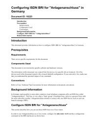
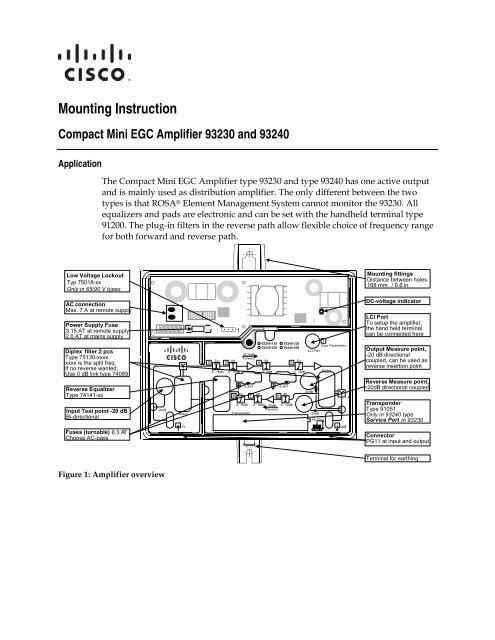
Application<br />
The <strong>Compact</strong> <strong>Mini</strong> <strong>EGC</strong> <strong>Amplifier</strong> type <strong>93230</strong> <strong>and</strong> type <strong>93240</strong> has one active output<br />
<strong>and</strong> is mainly used as distribution amplifier. The only different between the two<br />
types is that ROSA ® Element Management System cannot monitor the <strong>93230</strong>. All<br />
equalizers <strong>and</strong> pads are electronic <strong>and</strong> can be set with the h<strong>and</strong>held terminal type<br />
91200. The plug-in filters in the reverse path allow flexible choice of frequency range<br />
for both forward <strong>and</strong> reverse path.<br />
Low Voltage Lockout<br />
Typ 75018-xx<br />
Only in 65/90 V types<br />
<strong>Mounting</strong> fittings<br />
Distance between holes<br />
168 mm. / 6.6 in.<br />
AC connection<br />
Max. 7 A at remote supply<br />
Power Supply Fuse<br />
3.15 AT at remote supply<br />
2.0 AT at mains supply<br />
Diplex filter 2 pcs<br />
Type 75130-xxxx<br />
xxxx is the split freq.<br />
If no reverse wanted;<br />
Use 0 dB link type 74089<br />
Reverse Equalizer<br />
Type 74141-xx<br />
Input Test point -20 dB<br />
Bi-directional<br />
Fuses (turnable) 6.3 A T<br />
Choose AC-pass<br />
-20dB<br />
Diplex<br />
in<br />
1<br />
<strong>93240</strong>-138<br />
<strong>93240</strong>-238<br />
<strong>93240</strong>-338<br />
<strong>93240</strong>-938<br />
28/38dB<br />
Forward<br />
Eq Att Att Eq<br />
2 3 4<br />
5<br />
-9 ? 18dB 0 ? 18dB 0 ? 6dB<br />
6.3AT<br />
Eq Att<br />
8 7 6<br />
0 ? 15dB<br />
Transponder<br />
0 ? 18dB 25dB<br />
Reverse<br />
6.3AT<br />
Att<br />
0 ? 20dB<br />
0 ? 15dB<br />
1<br />
Copy Parameters<br />
LCI Port<br />
-20dB<br />
-20dB<br />
i n . 21 m m a x . 24 m m<br />
Diplex<br />
out<br />
DC- voltage indicator<br />
LCI Port<br />
To setup the amplifier,<br />
the h<strong>and</strong> held terminal<br />
can be connected here<br />
Output Measure point,<br />
-20 dB directional<br />
coupled, can be used as<br />
reverse insertion point<br />
Reverse Measure point,<br />
-20dB directional coupled<br />
Transponder<br />
Type 91051<br />
Only in <strong>93240</strong> type<br />
Service Port in <strong>93230</strong><br />
Connector<br />
PG11 at input <strong>and</strong> output<br />
Terminal for earthing<br />
Figure 1: <strong>Amplifier</strong> overview
<strong>Compact</strong> <strong>Mini</strong> <strong>EGC</strong> <strong>Amplifier</strong> <strong>93230</strong> <strong>and</strong> <strong>93240</strong><br />
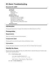
Housing Dimensions<br />
The st<strong>and</strong>ard housing dimensions are 7.3 inches/185 mm x 5.7 inches/145 mm x 3.7<br />
inches/95 mm.<br />
The distance from the top edge of the amplifier to its bottom edge is also 7.3<br />
inches/185 mm, as long as its length.<br />
The distance between two RF ports is 6.5 inches/116 mm.<br />
The diagram below shows the dimensions of the amplifier housing.<br />
2 <strong>Mounting</strong> Instructions <strong>Compact</strong> <strong>Mini</strong> <strong>EGC</strong> <strong>Amplifier</strong> <strong>93230</strong> <strong>and</strong> <strong>93240</strong> 4010069 Rev F
<strong>Compact</strong> <strong>Mini</strong> <strong>EGC</strong> <strong>Amplifier</strong> <strong>93230</strong> <strong>and</strong> <strong>93240</strong><br />
To Mount the <strong>Amplifier</strong><br />
CAUTION:<br />
Be aware of the size <strong>and</strong> weight of the amplifier when mounting. Ensure that<br />
the mounting location has a stable flat surface, <strong>and</strong> can safely support the<br />
amplifier’s maximum weight. Please use the appropriate type of screws <strong>and</strong><br />
screwdrivers, depending on the mounting method.<br />
<strong>Mounting</strong> Material:<br />
The amplifier should be mounted vertically with the cable input underneath, to allow<br />
natural ventilation <strong>and</strong> to secure the best possible operation conditions. Use a 4 mm<br />
Allen key for screw in lid <strong>and</strong> fasten with 5 Nm. The pin length of the PG 11 cable<br />
connector at input <strong>and</strong> output is shown on the cover plate of the amplifier. The<br />
amplifier can be mounted on the wall of concrete, brick, wood, metal, etc., or in the<br />
cabinet.<br />
<strong>Mounting</strong> Steps:<br />
1 Use two mounting screws to mount the amplifier. The screw size is M5 <strong>and</strong><br />
the distance between two mounting screws is 166 mm.<br />
2 Tighten the two mounting screws. Make sure the amplifier is fixed steadily.<br />
See the following diagram for instructions:<br />
4010069 Rev F <strong>Mounting</strong> Instructions <strong>Compact</strong> <strong>Mini</strong> <strong>EGC</strong> <strong>Amplifier</strong> <strong>93230</strong> <strong>and</strong> <strong>93240</strong> 3
<strong>Compact</strong> <strong>Mini</strong> <strong>EGC</strong> <strong>Amplifier</strong> <strong>93230</strong> <strong>and</strong> <strong>93240</strong><br />
Please Notice:<br />
Plug-in units<br />
This product can only be setup with a h<strong>and</strong> held terminal type A91200.11 or with a<br />
h<strong>and</strong> held terminal type A91200.10 containing the necessary driver for the <strong>EGC</strong><br />
amplifier. New drivers can be installed by means of download kit A91210.10.<br />
Three plug-in units are necessary.<br />
• Two diplex filters type 75130 with the required split frequency.<br />
Use two links type 74089 if the reverse path not is used.<br />
• Plug-in reverse equalizer type 74141 with the required filter frequency<br />
determines the frequency range for the built-in active reverse path.<br />
230 V AC<br />
DC<br />
AC or DC in<br />
DC<br />
0-18 dB<br />
Equalizer or<br />
Cable simulator<br />
-9 to18 dB<br />
0-6 dB<br />
0-15 dB<br />
µ-<br />
Controller<br />
TX<br />
Transponder<br />
RX<br />
-33dB<br />
-20dB<br />
0/6/∞<br />
0-18 dB<br />
Rev.Eq.<br />
0-15 dB<br />
0-20 dB<br />
-20dB<br />
TP<br />
-20dB<br />
TP<br />
-20dB<br />
Rev. TP<br />
IN OUT 1<br />
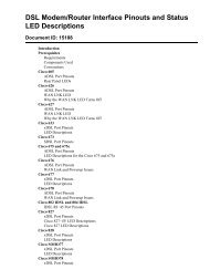
Figure 2: Block diagram for the amplifier type <strong>93230</strong> <strong>and</strong> type <strong>93240</strong>.<br />
The transponder <strong>and</strong> tri-state switch cannot be used in the amplifier type <strong>93230</strong><br />
4 <strong>Mounting</strong> Instructions <strong>Compact</strong> <strong>Mini</strong> <strong>EGC</strong> <strong>Amplifier</strong> <strong>93230</strong> <strong>and</strong> <strong>93240</strong> 4010069 Rev F
<strong>Compact</strong> <strong>Mini</strong> <strong>EGC</strong> <strong>Amplifier</strong> <strong>93230</strong> <strong>and</strong> <strong>93240</strong><br />
Power Supply<br />
230 V (or 115 V) Mains Supply<br />
The amplifier has factory mounted mains cable <strong>and</strong> plugs, which according to<br />
approval provisions may not be altered. The power unit is double insulated, <strong>and</strong><br />
supplies only this single amplifier. When the power unit DC voltage lights indicate<br />
the power unit is supplying correct DC voltage.<br />
Remote Supply 24-65 V AC (or 35-90 V AC)<br />
The amplifier can be supplied with 24-65 V AC either via coaxial cables (max. 5 A) or<br />
directly to the AC input (max. 7 A).<br />
AC Pass<br />
On delivery, ports are provided with insulating fuses. Desired AC pass is obtained<br />
by turning the fuse holder after connecting the cable or before disconnecting, to<br />
prevent damage of cable connectors.<br />
Permanent excess of max. Remote current implies a risk of damage.<br />
Low Voltage Lockout<br />
For all coax line powered power supplies an undervoltage switch type 75018-xx can<br />
be delivered that switches off the power supply if the voltage drops below the rated<br />
value (24 V or 35 V) thus, the network is not damaged due to increased current<br />
consumption.<br />
Setting up the amplifier<br />
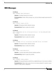
The h<strong>and</strong> held terminal type 91200 is used to set up the amplifier. Use the menu<br />
structure below to navigate through the different menus.<br />
Shortcuts<br />
Use the short cuts shown on the cover plate to do a fast selection of the required<br />
menu. Ex. The output equalizer is marked with 5 . By pressing the button”5” in<br />
approx. 1 sec. the terminal returns to the menu where the output equalizer can be is<br />
changed.<br />
The menu numbers can also be used as short cuts. Please see the menus structure<br />
below to determine the number for the required menu. Ex. Press”35” <strong>and</strong> the<br />
h<strong>and</strong>held terminal will return to the menu where the reverse switch can be set.<br />
4010069 Rev F <strong>Mounting</strong> Instructions <strong>Compact</strong> <strong>Mini</strong> <strong>EGC</strong> <strong>Amplifier</strong> <strong>93230</strong> <strong>and</strong> <strong>93240</strong> 5
<strong>Compact</strong> <strong>Mini</strong> <strong>EGC</strong> <strong>Amplifier</strong> <strong>93230</strong> <strong>and</strong> <strong>93240</strong><br />
Or use the following buttons:<br />
or<br />
or<br />
Is used to navigate to the<br />
submenus <strong>and</strong> to open a menu<br />
for editing. The value can then<br />
be changed. Additional the<br />
button can be used to reject a<br />
value entered by the keypad.<br />
Is used to navigate to the root<br />
menus <strong>and</strong> to delete wrong<br />
digits when a menu is open<br />
for editing. Additional the<br />
button can be used to reject a<br />
value entered by the keypad.<br />
Configuration<br />
1 Fw 28dB/862M<br />
Configuration<br />
1 Rv 25dB<br />
Forward<br />
2<br />
Toggling<br />
*<br />
Forward Gain<br />
11 28 dB<br />
Forward Freq.<br />
12 862 MHz<br />
Reverse Gain<br />
13 25 dB<br />
Input EQ<br />
21 + 5.0 dB<br />
Input Att<br />
22 + 5.0 dB<br />
Interstage Att<br />
23 + 5.0 dB<br />
Interstage Att 2<br />
24 + 5.0 dB<br />
Output EQ<br />
25 + 5.0 dB<br />
**<br />
1 2 3<br />
4 5 6<br />
7 8 9<br />
• 0 -<br />
E<br />
N<br />
TE<br />
R<br />
All numbers, ”.” <strong>and</strong> ”-” are<br />
used to enter values with. The<br />
numbers can also be used as<br />
short cuts.<br />
Is used to navigate through<br />
menus at the same level <strong>and</strong> to<br />
select the settings in some<br />
menus. Additional these<br />
buttons can be used to finetune<br />
some values.<br />
Is used to confirm a setting or<br />
a change.<br />
Reverse<br />
3<br />
Supply<br />
4<br />
Copy Parameters<br />
5<br />
Rev. Input Att 1<br />
31 + 5.0 dB<br />
Rev. Input Att 2<br />
32 + 5.0 dB<br />
Rev. Output Att<br />
33 + 5.0 dB<br />
Rev. Output EQ<br />
34 + 5.0 dB<br />
Rev. Switch<br />
35 0 dB<br />
Remote Supply<br />
41 Not Connected<br />
From Product<br />
51 To Product<br />
52<br />
Restore Default<br />
53<br />
**<br />
In the menu ”Copy Parameters” the<br />
setting of an amplifier can be saved<br />
(menu 51) <strong>and</strong> downloaded to another<br />
amplifier (menu 52).<br />
Identification<br />
6<br />
* old terminal design<br />
**<br />
Not avaiable for<br />
this amplifier<br />
*<br />
Model Number<br />
61 A<strong>93240</strong>.10238<br />
Serial Number<br />
62Time in 000423F0434<br />
Service<br />
63 Software ID 2 days<br />
64Terminal SW 7003460-A<br />
65 530445<br />
Transponder<br />
66 OK<br />
Lid Status<br />
67 Open<br />
Lid status menu only in <strong>93240</strong><br />
Figure 3: Menu structure<br />
6 <strong>Mounting</strong> Instructions <strong>Compact</strong> <strong>Mini</strong> <strong>EGC</strong> <strong>Amplifier</strong> <strong>93230</strong> <strong>and</strong> <strong>93240</strong> 4010069 Rev F
<strong>Compact</strong> <strong>Mini</strong> <strong>EGC</strong> <strong>Amplifier</strong> <strong>93230</strong> <strong>and</strong> <strong>93240</strong><br />
ROSA Element Management System in Type <strong>93240</strong><br />
Monitoring of the amplifier requires the installation of the transponder type 91051 in<br />
the amplifier. This transponder will communicate back to the head-end by means of<br />
the reverse path. The transponder signal is received at the test point at output. Please<br />
see fig. 2. The level measured by the transponder will be attenuated by approx. 33 dB<br />
relative to the output signal at output. The transponder transmitter level is adjusted<br />
to the same level as the other reverse signals. The level from the transponder will be<br />
attenuated by approx. 20 dB at the reverse path since it is inserted with a 20 dB<br />
coupler.<br />
With a transponder it is possible to monitor <strong>and</strong> control different parameters in the<br />
amplifier. As seen in Fig. 2, the built-in reverse path switch can be controlled in<br />
order to locate ingress noise in the reverse path – This can be useful in the search for<br />
errors in larger networks.<br />
Programming of a <strong>Compact</strong> Transponder type 91051 is done by using the H<strong>and</strong>held<br />
Terminal 91200. The transponder can be set with:<br />
SMC ID Transponder adress 1-65535<br />
TX FREQ Transmit frequency 5-65 MHz<br />
RX FREQ Receive frequency 45-174 MHz<br />
TX LEVEL Transmit level 84-110 dBµV<br />
BAUD RATE Data speed 9.6-19.2-38.4 kbps<br />
MODE Transponder mode IEP<br />
Accessories<br />
Test adapter, F type<br />
A71004<br />
Fuses<br />
2AT, for 230 Vac<br />
A38008<br />
2AT, for 115 VAC<br />
A38024<br />
3.15AT, for 24-65 V (35-90 V)<br />
A38010<br />
6.3 AT, for input/output port A38015<br />
4010069 Rev F <strong>Mounting</strong> Instructions <strong>Compact</strong> <strong>Mini</strong> <strong>EGC</strong> <strong>Amplifier</strong> <strong>93230</strong> <strong>and</strong> <strong>93240</strong> 7
For Information<br />
If You Have Questions<br />
Region Centers Customer Service Numbers<br />
North America USA • Toll-free: 1-800-722-2009<br />
Europe, Middle East, Africa Belgium • Telephone: 32-56-445-133 or 32-56-445-118<br />
Japan Japan • Telephone: 81-3-5908-2153 or +81-3-5908-2154<br />
Korea Korea • Telephone: 82-2-6205-6004<br />
China (mainl<strong>and</strong>) China • Telephone: 86-400-8108886 Press 4 at the prompt<br />
Other Asia-Pacific countries, Australia Hong Kong • Telephone: 852-2522-5059<br />
Brazil Brazil • Telephone: 55-11-3845-9154, ext 109<br />
Mexico, Central America, Caribbean Mexico • Telephone: 52-55-50-81-8425<br />
All other Latin America countries Argentina • Telephone: 770-236-5662<br />
<strong>Cisco</strong> Systems, Inc.<br />
5030 Sugarloaf Parkway, Box 465447<br />
Lawrenceville, GA 30042<br />
678 277-1120<br />
800 722-2009<br />
www.cisco.com<br />
<strong>Cisco</strong> <strong>and</strong> the <strong>Cisco</strong> logo are trademarks or registered trademarks of <strong>Cisco</strong> <strong>and</strong>/or its affiliates<br />
in the U.S. <strong>and</strong> other countries. A listing of <strong>Cisco</strong>'s trademarks can be found<br />
at www.cisco.com/go/trademarks.<br />
Third party trademarks mentioned are the property of their respective owners.<br />
The use of the word partner does not imply a partnership relationship between <strong>Cisco</strong> <strong>and</strong> any<br />
other company.<br />
(1009R)<br />
Specifications <strong>and</strong> product availability are subject to change without notice.<br />
© 2012 <strong>Cisco</strong> <strong>and</strong>/or its affiliates. All rights reserved.<br />
June 2012<br />
Part Number 4010069 Rev F