midi/smpte interface card installation & setup - Strand Lighting
midi/smpte interface card installation & setup - Strand Lighting
midi/smpte interface card installation & setup - Strand Lighting

Create successful ePaper yourself
Turn your PDF publications into a flip-book with our unique Google optimized e-Paper software.
Light Palette Control Console<br />
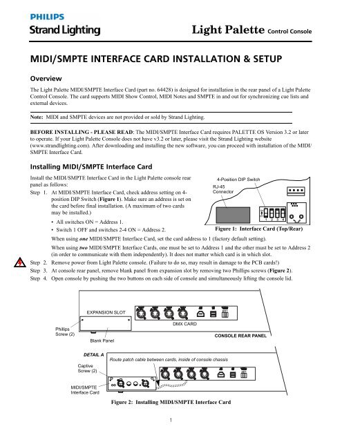
MIDI/SMPTE INTERFACE CARD INSTALLATION & SETUP<br />
Overview<br />
The Light Palette MIDI/SMPTE Interface Card (part no. 64428) is designed for <strong>installation</strong> in the rear panel of a Light Palette<br />
Control Console. The <strong>card</strong> supports MIDI Show Control, MIDI Notes and SMPTE in and out for synchronizing cue lists and<br />
external devices.<br />
Note: MIDI and SMPTE devices are not provided or sold by <strong>Strand</strong> <strong>Lighting</strong>.<br />
BEFORE INSTALLING - PLEASE READ: The MIDI/SMPTE Interface Card requires PALETTE OS Version 3.2 or later<br />
to operate. If your Light Palette Console does not have v3.2 or later, please visit the <strong>Strand</strong> <strong>Lighting</strong> website<br />
(www.strandlighting.com). After downloading and installing the new software, you can proceed with <strong>installation</strong> of the MIDI/<br />
SMPTE Interface Card.<br />
Installing MIDI/SMPTE Interface Card<br />
Install the MIDI/SMPTE Interface Card in the Light Palette console rear<br />
panel as follows:<br />
Step 1. At MIDI/SMPTE Interface Card, check address setting on 4-<br />
position DIP Switch (Figure 1). Make sure an address is set on<br />
the <strong>card</strong> before final <strong>installation</strong>. (A maximum of two <strong>card</strong>s<br />
may be installed.)<br />
• All switches ON = Address 1.<br />
• Switch 1 OFF and switches 2-4 ON = Address 2.<br />
4-Position DIP Switch<br />
RJ-45<br />
Connector<br />
Figure 1: Interface Card (Top/Rear)<br />
When using one MIDI/SMPTE Interface Card, set the <strong>card</strong> address to 1 (factory default setting).<br />
When using two MIDI/SMPTE Interface Cards, one must be set to Address 1 and the other must be set to Address 2<br />
(in order to communicate with them independently). It does not matter which <strong>card</strong> is in which slot.<br />
Step 2. Remove power from Light Palette console. (Failure to do so, may result in damage to the PCB <strong>card</strong>s!)<br />
Step 3. At console rear panel, remove blank panel from expansion slot by removing two Phillips screws (Figure 2).<br />
Step 4. Open console by pushing the two buttons on each side of console and simultaneously lifting the console lid.<br />
EXPANSION SLOT<br />
Phillips<br />
Screw (2)<br />
Blank Panel<br />
DMX CARD<br />
CONSOLE REAR PANEL<br />
DETAIL A<br />
Captive<br />
Screw (2)<br />
Route patch cable between <strong>card</strong>s, inside of console chassis<br />
MIDI/SMPTE<br />
Interface Card<br />
Figure 2: Installing MIDI/SMPTE Interface Card<br />
1
Light Palette Control Console<br />
Step 5. Connect RJ-45 Patch Cable (included) to any open RJ-45 connector at rear of DMX Card (not on the front of the<br />
<strong>card</strong>).<br />
Note: On Light Palette VL and Light Palette Live consoles, all open connectors on the DMX <strong>card</strong> may be in use. If you are<br />
installing this <strong>card</strong> in one of these consoles, please use any open connector on a submaster or button module panel.<br />
Step 6. Feed Patch Cable inside console chassis and route toward expansion slot as shown in Figure 2. Slide DMX Card<br />
back into its slot and secure by hand-tightening two captive screws.<br />
Step 7. Insert MIDI/SMPTE Interface Card into slot and secure by hand-tightening two captive screws.<br />
Step 8. Connect remaining end of Patch Cable to either RJ-45 connector at rear of <strong>card</strong>.<br />
Step 9. Close console lid.<br />
Connecting MIDI and SMPTE Devices<br />
The hardware will support up to two external SMPTE<br />
<strong>interface</strong> devices and the software additionally supports<br />
four internal SMPTE clocks and the Media Player Time<br />
Code.<br />
• MIDI devices connect using the industry standard MIDI<br />
connector (DIN 5).<br />
• SMPTE connects using a balanced line level signal<br />
through standard XLR connectors.<br />
• A potentiometer is provided to adjust the level of the<br />
SMPTE output signal.<br />
LED Operation<br />
SMPTE Out<br />
COM LED<br />
Level Adjustment<br />
Status LED<br />
SMPTE In<br />
MIDI Out<br />
MIDI In<br />
Figure 3: Connecting MIDI/SMPTE Devices<br />
During console operation, the MIDI/SMPTE Interface Card LEDs will indicate the following conditions:<br />
COM LED<br />
Green Flash = No MIDI/SMPTE<br />
Red Flash = Transmit SMPTE<br />
Green/Red = Receive SMPTE<br />
Status LED<br />
No LED = No power<br />
Solid Green = Power, CPU not running<br />
Amber/Green Slow Flash = No communication to console<br />
Amber/Green Fast Flash = Connected to console<br />
Refer to the Light Palette Help file for more information regarding MIDI or SMPTE operation.<br />
Customer Support<br />
Contact <strong>Strand</strong> <strong>Lighting</strong> Customer Service at: 1-800-4STRAND (U.S.) or 1-214-647-7880 (international).<br />
For a complete list of support and field service contacts, go to www.strandlighting.com, select the Support tab and then the<br />
"Support/Field Service Contacts" link.<br />
Philips<br />
<strong>Strand</strong> <strong>Lighting</strong><br />
10911 Petal Street<br />
Dallas, TX 75238 USA<br />
Tel: 214-647-7880 | Fax: 214-647-8031<br />
www.strandlighting.com<br />
©2011 Philips Group<br />
Document Number: 85-6147