KFX450 Dyna FS Ignition
KFX450 Dyna FS Ignition
KFX450 Dyna FS Ignition

Create successful ePaper yourself
Turn your PDF publications into a flip-book with our unique Google optimized e-Paper software.
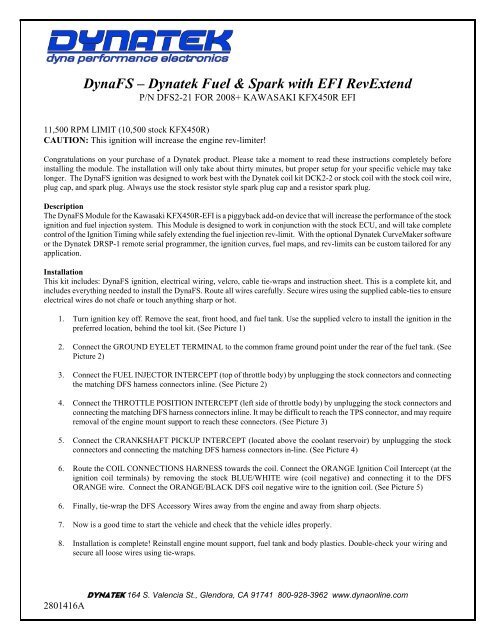
<strong>Dyna</strong><strong>FS</strong> – <strong>Dyna</strong>tek Fuel & Spark with EFI RevExtend<br />
P/N D<strong>FS</strong>2-21 FOR 2008+ KAWASAKI <strong>KFX450</strong>R EFI<br />
11,500 RPM LIMIT (10,500 stock <strong>KFX450</strong>R)<br />
CAUTION: This ignition will increase the engine rev-limiter!<br />
Congratulations on your purchase of a <strong>Dyna</strong>tek product. Please take a moment to read these instructions completely before<br />
installing the module. The installation will only take about thirty minutes, but proper setup for your specific vehicle may take<br />
longer. The <strong>Dyna</strong><strong>FS</strong> ignition was designed to work best with the <strong>Dyna</strong>tek coil kit DCK2-2 or stock coil with the stock coil wire,<br />
plug cap, and spark plug. Always use the stock resistor style spark plug cap and a resistor spark plug.<br />
Description<br />
The <strong>Dyna</strong><strong>FS</strong> Module for the Kawasaki <strong>KFX450</strong>R-EFI is a piggyback add-on device that will increase the performance of the stock<br />
ignition and fuel injection system. This Module is designed to work in conjunction with the stock ECU, and will take complete<br />
control of the <strong>Ignition</strong> Timing while safely extending the fuel injection rev-limit. With the optional <strong>Dyna</strong>tek CurveMaker software<br />
or the <strong>Dyna</strong>tek DRSP-1 remote serial programmer, the ignition curves, fuel maps, and rev-limits can be custom tailored for any<br />
application.<br />
Installation<br />
This kit includes: <strong>Dyna</strong><strong>FS</strong> ignition, electrical wiring, velcro, cable tie-wraps and instruction sheet. This is a complete kit, and<br />
includes everything needed to install the <strong>Dyna</strong><strong>FS</strong>. Route all wires carefully. Secure wires using the supplied cable-ties to ensure<br />
electrical wires do not chafe or touch anything sharp or hot.<br />
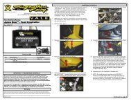
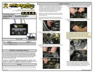
1. Turn ignition key off. Remove the seat, front hood, and fuel tank. Use the supplied velcro to install the ignition in the<br />
preferred location, behind the tool kit. (See Picture 1)<br />
2. Connect the GROUND EYELET TERMINAL to the common frame ground point under the rear of the fuel tank. (See<br />
Picture 2)<br />
3. Connect the FUEL INJECTOR INTERCEPT (top of throttle body) by unplugging the stock connectors and connecting<br />
the matching D<strong>FS</strong> harness connectors inline. (See Picture 2)<br />
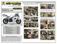
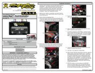
4. Connect the THROTTLE POSITION INTERCEPT (left side of throttle body) by unplugging the stock connectors and<br />
connecting the matching D<strong>FS</strong> harness connectors inline. It may be difficult to reach the TPS connector, and may require<br />
removal of the engine mount support to reach these connectors. (See Picture 3)<br />
5. Connect the CRANKSHAFT PICKUP INTERCEPT (located above the coolant reservoir) by unplugging the stock<br />
connectors and connecting the matching D<strong>FS</strong> harness connectors in-line. (See Picture 4)<br />
6. Route the COIL CONNECTIONS HARNESS towards the coil. Connect the ORANGE <strong>Ignition</strong> Coil Intercept (at the<br />
ignition coil terminals) by removing the stock BLUE/WHITE wire (coil negative) and connecting it to the D<strong>FS</strong><br />
ORANGE wire. Connect the ORANGE/BLACK D<strong>FS</strong> coil negative wire to the ignition coil. (See Picture 5)<br />
6. Finally, tie-wrap the D<strong>FS</strong> Accessory Wires away from the engine and away from sharp objects.<br />
7. Now is a good time to start the vehicle and check that the vehicle idles properly.<br />
8. Installation is complete! Reinstall engine mount support, fuel tank and body plastics. Double-check your wiring and<br />
secure all loose wires using tie-wraps.<br />
DYNATEK 164 S. Valencia St., Glendora, CA 91741 800-928-3962 www.dynaonline.com<br />
2801416A
Picture 1: Picture 2:<br />
Picture 3: Picture 4:<br />
Picture 5:<br />
DYNATEK 164 S. Valencia St., Glendora, CA 91741 800-928-3962 www.dynaonline.com<br />
2801416A
Calibration<br />
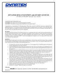
The <strong>Dyna</strong><strong>FS</strong> is pre-programmed with a performance advance curve, +4° over stock, and an 11,500 RPM rev-limit. A quicker<br />
throttle response and increased power over the stock curve is achieved. To select another advance curve, use the DRSP-1<br />
Programmer. For other advance curve information, see the attached Advance Chart. The <strong>Dyna</strong><strong>FS</strong> will allow the engine to rev to a<br />
higher RPM, and is adjustable to 12,000 RPM max by using the CurveMaker software. Because the rev limit is increased, the<br />
performance limits of other engine parts (valve train or piston for example) may be found. It may be necessary to replace these<br />
parts for best engine performance. The <strong>Dyna</strong><strong>FS</strong> is shipped from <strong>Dyna</strong>tek with 0% adjustments to all of the fuel injection settings.<br />
For more information on fuel settings, see the section on Using the DRSP-1 Remote Programmer, and the Fuel Curves Chart.<br />
Using the DRSP-1 Remote Serial Programmer<br />
The DRSP-1 Remote Serial Programmer (sold separately) is a plug-in programmer for adjusting the fuel injection and ignition<br />
advance curves. Simply plug the DRSP-1 into the D<strong>FS</strong> HARNESS and mount the Remote for easy access. The Remote<br />
allows adjustment to the stock fuel injections signal in multiple stages.<br />
NOTE: It is HIGHLY RECOMMENDED to use a wide band oxygen sensor and quality gauge (such as Dynojet’s Wide Band<br />
Commander) when tuning the fuel injection. Without a gauge, the air/fuel ratio cannot be determined and possible engine<br />
damage can occur.<br />
FUEL BASE – this setting will adjust the entire fuel map: 1 = 0% 2 = +10% 3 = +20% 4 = +40%<br />
FUEL LOW – this setting will adjust fuel from 0 rpm to 6,000 rpm, in the ranges of: -17.5% to 0% to +20%<br />
FUEL MID – this setting will adjust fuel from 6,001 rpm to 9,000 rpm, in the ranges of: -17.5% to 0% to +20%<br />
FUEL HIGH – this setting will adjust fuel from 9,001 rpm to 12,000 rpm, in the ranges of: -17.5% to 0% to +20%<br />
IGN CURVE – this setting will adjust the <strong>Ignition</strong> Curve, up to 4 selectable and all can be custom programmed using the<br />
CurveMaker Software. (see attached Curve Chart)<br />
NOTE: The DRSP-1 can be removed after adjusting the settings, and the <strong>Dyna</strong><strong>FS</strong> will keep the settings even with the battery<br />
disconnected. If the LED on the Remote does not turn on, or the LED flashes continuously after 10 seconds, then the ignition<br />
and Remote should be returned to <strong>Dyna</strong>tek for testing.<br />
Additional Features<br />
The D<strong>FS</strong> for the <strong>KFX450</strong>R has many additional features. These are pre-programmed and they all can be accessed using <strong>Dyna</strong>tek<br />
CurveMaker Software (not supplied with the ignition). If the ignition was not purchased directly from <strong>Dyna</strong>tek, the dealer may<br />
have programmed a custom set of ignition curves and fuel injection settings. The dealer should be consulted with any questions<br />
regarding the curves and settings that are programmed into the ignition.<br />
The D<strong>FS</strong> ignition for the Kawasaki <strong>KFX450</strong>R is shipped with additional leads coming out of the ignition. These leads allow the<br />
ignition to control other features. To program these features, follow the instructions in the programming kit.<br />
BLACK/YELLOW – Programmable Launch Limiter. Ground this wire to activate, preset at 4,500 RPM (0-10,000 RPM adjustable<br />
using CurveMaker software)<br />
BLUE – Optional 2-amp RPM window activated switch to ground, referenced as “RPM Switch 1” in PC Software.<br />
WHITE/BLUE – Optional 2-amp RPM window activated switch to ground, referenced as “RPM Switch 2” in PC Software.<br />
The Blue and White/Blue wires are 2-amp switches that can be used to activate a solenoid or relay. Connect the relay with hot<br />
+12v wired to one side of the relay coil, and the other side connected to Blue or White/Blue. When the rpm activates the switch, it<br />
will be grounded inside the ignition box, causing current to flow through the relay coil. DO NOT connect any device which<br />
requires more than 2 Amps (Amps=Volts/Resistance). See attached wiring diagram for wiring the relay.<br />
Data Recording<br />
The <strong>Dyna</strong>tek D<strong>FS</strong> will continuously record important engine operating parameters. This information can only be accessed through<br />
the <strong>Dyna</strong>tek CurveMaker in the Diagnostics Tab of the software (sold separately). The recorded data includes:<br />
Number of Engine Starts (recorded after 2.25min of run time)<br />
Total Time Engine at WOT (hours)<br />
Total Operating Time (hours)<br />
Longest Continuous WOT Operation (seconds)<br />
Histograph Bar Chart of Engine Speed VS. Time<br />
Maximum Engine Speed<br />
Time Near Rev Limit<br />
Programmed Rev Limit<br />
DYNATEK 164 S. Valencia St., Glendora, CA 91741 800-928-3962 www.dynaonline.com<br />
2801416A
Troubleshooting<br />
Troubleshooting the <strong>Dyna</strong> ignition is simple. If the dashboard “Check Engine Light” is ON, or the vehicle will not start or run at<br />
all, follow these 3 steps:<br />
1) Disconnect the Fuel Injector Intercept connectors and reconnect the stock connector to the fuel injector,<br />
2) Disconnect the D<strong>FS</strong> ORANGE/BLACK coil negative wire, and reconnect the stock BLUE/WHITE wire back to the<br />
ignition coil negative.<br />
If this fixes the problem, then the <strong>Dyna</strong> ignition should be returned to <strong>Dyna</strong>tek for testing. If this does not fix the problem, then the<br />
problem is somewhere else on the engine or vehicle. Follow the troubleshooting procedures outlined in your vehicle shop manual.<br />
If you are using non stock spark plug, or stator, replace them with OEM units. Then follow the procedures in the calibration<br />
section to set the <strong>Dyna</strong> ignition up to work with your vehicle. If calibration doesn't fix the problem, the ignition should be<br />
returned for testing. If the problem persists when using the stock ignition then the problem is external to the <strong>Dyna</strong> ignition.<br />
Examples of RPM Activated Switch wiring:<br />
DYNATEK 164 S. Valencia St., Glendora, CA 91741 800-928-3962 www.dynaonline.com<br />
2801416A<br />
FUEL4<br />
FUEL3<br />
FUEL2<br />
FUEL<br />
STOC K<br />
1<br />
DE OPEN<br />
ROTTLE<br />
L MAPS<br />
OT SHOWN
DYNATEK 164 S. Valencia St., Glendora, CA 91741 800-928-3962 www.dynaonline.com<br />
2801416A
DYNA D<strong>FS</strong>2-21 / KAWASAKI <strong>KFX450</strong>R - IGNITION CURVES<br />
RPM / 1000<br />
ALL BASE MODULES USE CURVE 2<br />
CURVE4 = STOCK ADVANCE<br />
(Assumes 10° base timing)<br />
PART-<br />
THROTTLE<br />
CURVE2<br />
CURVE1<br />
CURVE4<br />
STOCK<br />
CURVE3<br />
RETARD<br />
CURVE2<br />
ADVANCED<br />
WIDE OPEN<br />
THROTTLE<br />
(Curves 1-4)<br />
IGNITION ADVANCE (CRANKSHAFT DEGREES)<br />
DYNATEK 164 S. Valencia St., Glendora, CA 91741 800-928-3962 www.dynaonline.com<br />
2801416A