for R&S®EB500 Monitoring Receiver - Rohde & Schwarz Singapore
for R&S®EB500 Monitoring Receiver - Rohde & Schwarz Singapore
for R&S®EB500 Monitoring Receiver - Rohde & Schwarz Singapore

Create successful ePaper yourself
Turn your PDF publications into a flip-book with our unique Google optimized e-Paper software.
<br />
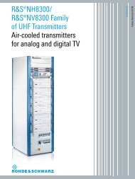
R&S®EB500<br />
<strong>Monitoring</strong> <strong>Receiver</strong><br />
High-per<strong>for</strong>mance<br />
radiomonitoring<br />
from 9 kHz to 6 GHz<br />
Radiomonitoring & Radiolocation<br />
Product Brochure | 03.01
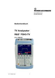
R&S®EB500<br />
<strong>Monitoring</strong> <strong>Receiver</strong><br />
At a glance<br />
The R&S®EB500 monitoring receiver is designed to<br />
meet the demanding requirements of ITU-compliant<br />
radiomonitoring tasks in stationary and mobile<br />
environments. The receiver is the ideal choice <strong>for</strong><br />
these tasks because it is capable of operation via<br />
the front panel or remote control software, per<strong>for</strong>ms<br />
high-speed signal searches in the spectrum,<br />
and gathers in<strong>for</strong>mation by means of wideband<br />
demodulation. In addition, the R&S®EB500 can be<br />
used <strong>for</strong> a variety of other applications.<br />
The R&S®EB500 monitoring receiver has an outstanding<br />
feature set <strong>for</strong> monitoring transmissions, detecting interference,<br />
locating unlicensed transmitters in the frequency<br />
spectrum, or even functioning as a search receiver. In addition,<br />
it is exceptionally compact and consumes relatively<br />
little power. The R&S®EB500 is the optimum solution <strong>for</strong><br />
systems that need a high specification receiver but only<br />
have limited available space. When combined with analysis<br />
software (such as R&S®GX430, <strong>for</strong> example), it provides<br />
users with a compact receiving and analysis system covering<br />
a wide frequency range from 9 kHz to 6 GHz.<br />
The receiver can be operated with diverse antennas such<br />
as broadband omnidirectional antennas and directional<br />
antennas. To limit overloading when used with omnidirectional<br />
antennas, the R&S®EB500 is equipped with a<br />
preselection stage (as recommended by ITU) that avoids<br />
intermodulation and overloading.<br />
Due to its compact size and excellent balance between<br />
per<strong>for</strong>mance and power consumption, the R&S®EB500<br />
is designed not just <strong>for</strong> stationary operation but also<br />
<strong>for</strong> installation in vehicles, in aircraft (as payload) or in<br />
unmanned aerial vehicles (UAV).<br />
Key facts<br />
❙❙Fast panorama scan with up to 12 GHz/s across the<br />
entire frequency range from 9 kHz to 6 GHz<br />
❙❙1 kHz to 20 MHz IF spectrum and parallel demodulation<br />
with bandwidths from 100 Hz to 20 MHz<br />
❙❙Spectrum and spectrogram (waterfall) display on receiver<br />
(model .03) or on PC via the R&S®EB500-Control software<br />
(model .02)<br />
❙❙Can be expanded into a direction finder<br />
❙❙Polychrome IF spectrum <strong>for</strong> reliable detection of pulsed<br />
signals<br />
❙❙1 Gbit LAN interface <strong>for</strong> remote control and data output<br />
❙❙Comparatively low power consumption <strong>for</strong> efficient<br />
DC operation, e.g. on a vehicle battery<br />
❙❙Space-saving system integration due to ½ 19" width and<br />
three height units<br />
❙❙Classification and analysis of signals up to 5 MHz<br />
bandwidth (analog and digital modulation) through<br />
evaluation of the I/Q data stream using the R&S®GX430IS<br />
software (in offline mode), <strong>for</strong> example<br />
❙❙Multichannel digital downconversion (DDC) within<br />
realtime bandwidth<br />
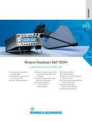
Front panel without control elements,<br />
remote control via LAN interface.<br />
2
R&S®EB500<br />
<strong>Monitoring</strong> <strong>Receiver</strong><br />
Applications<br />
Interference detection and location in professional<br />
radio networks<br />
❙❙Reliable detection of radio interference caused, <strong>for</strong><br />
example, by defective electronic equipment<br />
❙❙Fast and effective identification of interference sources,<br />
e.g. at airports<br />
▷▷<br />
page 5<br />
Comprehensive spectrum analysis with<br />
polychrome display<br />
❙❙Polychrome display <strong>for</strong> detection and analysis of shortduration<br />
signals<br />
▷▷<br />
page 6<br />
<strong>Monitoring</strong> of user-specific radio services<br />
❙❙<strong>Monitoring</strong> of a large number of radio services with<br />
different scan modes<br />
▷▷<br />
page 7<br />
Multichannel digital downconversion (DDC)<br />
❙❙Parallel monitoring of one plus three signals<br />
❙❙All DDC channels user-selectably distributed within<br />
realtime bandwidth<br />
❙❙Independent demodulation, level measurement and<br />
recording of each channel<br />
▷▷<br />
page 8<br />
Nationwide monitoring system <strong>for</strong> regulatory<br />
authorities<br />
❙❙ITU-compliant spectrum monitoring using the<br />
R&S®ARGUS system software<br />
■■<br />
When combined with the R&S®ARGUS spectrum<br />
monitoring software, the receiver reliably and<br />
efficiently per<strong>for</strong>ms all key measurements listed in<br />
the ITU spectrum monitoring handbook and related<br />
recommendations<br />
▷▷<br />
page 9<br />
Handoff receiver in networked systems<br />
❙❙Parallel demodulation of multiple narrowband signals and<br />
simultaneous broadband spectrum scanning<br />
▷▷<br />
page 11<br />
<strong>Rohde</strong> & <strong>Schwarz</strong> R&S®EB500 <strong>Monitoring</strong> <strong>Receiver</strong> 3
R&S®EB500<br />
<strong>Monitoring</strong> <strong>Receiver</strong><br />
Key features<br />
High receiver sensitivity, high signal resolution<br />
❙❙State-of-the-art FFT-based digital signal processing <strong>for</strong><br />
high receiver sensitivity and detection of extremely weak<br />
signals without any loss in processing speed<br />
❙❙Significantly superior receiver sensitivity and signal<br />
resolution (compared with conventional analog<br />
broadband receivers)<br />
▷▷<br />
page 15<br />
Retrieval of in<strong>for</strong>mation through demodulation<br />
and signal analysis in a compact system<br />
❙❙Online LAN transfer from an R&S®EB500 to a PC and the<br />
R&S®GX430 analysis software, <strong>for</strong> example, <strong>for</strong> operating<br />
an efficient small system <strong>for</strong> signal reception and analysis<br />
❙❙Online analysis or recording of captured data using<br />
R&S®GX430, provision of data <strong>for</strong> documentation, replay<br />
or subsequent additional evaluation<br />
❙❙ITU-compliant signal analysis in line with ITU-R SM.1600<br />
using R&S®GX430 and R&S®GX430IS, optimum tool<br />
<strong>for</strong> single-channel analysis and measurement of analog<br />
and digitally modulated signals in accordance with<br />
ITU requirements<br />
Efficient operation via remote control<br />
❙❙Remote control of all receiver functions via LAN interface<br />
(SCPI command set)<br />
❙❙LAN interface <strong>for</strong> providing the maximum measured<br />
data rate during receiver operation; efficient remote<br />
operation in unattended monitoring stations (interface<br />
essential, especially <strong>for</strong> systems integrators who need<br />
to incorporate the receiver into existing software<br />
environments)<br />
Convenient remote control with<br />
R&S®EB500‐Control software<br />
❙❙Short learning curve due to straight<strong>for</strong>ward menu<br />
structure and simple operation<br />
❙❙Alignment of displayed signals (depending on task),<br />
optimum display on screen<br />
❙❙Remote control of receiver via PC, recording of measured<br />
data on hard disk and replay of data on PC <strong>for</strong> analysis<br />
purposes<br />
❙❙Expansion of remote control software functionality<br />
through options and add-ons from the R&S®RAMON<br />
software suite<br />
▷▷<br />
page 12<br />
Precise direction finding of emissions (with<br />
R&S®EB500-DF direction finder upgrade kit)<br />
❙❙Fast, reliable direction finding due to high DF accuracy<br />
❙❙Direction finding up to 6 GHz<br />
▷▷<br />
page 14<br />
Future-ready investment<br />
❙❙Wide frequency range and outstanding per<strong>for</strong>mance<br />
❙❙Capable of receiving, demodulating and processing<br />
signals of current and future radio services<br />
4
Interference<br />
detection and<br />
location in<br />
professional radio<br />
networks<br />
Its high per<strong>for</strong>mance and wide range of special<br />
functions make the R&S®EB500 an ideal choice <strong>for</strong><br />
detecting all types of radio interference efficiently.<br />
Reliable detection of radio interference caused, <strong>for</strong><br />
example, by defective electronic equipment<br />
To master these tasks, the receiver includes special functions<br />
such as selectable measurement time and continuous<br />
or periodic level output. Since these functions are<br />
also effective in the panorama scan spectrum, even nonperiodic<br />
interferers can be easily detected. Such interferers<br />
are otherwise very difficult to detect due to their irregular<br />
appearance in a quickly changing spectrum.<br />
Fast and effective identification of interference<br />
sources, e.g. at airports<br />
The simultaneous use of the R&S®GX430 analysis software<br />
allows efficient differentiation between wanted signals and<br />
possible interference signals. Fast differentiation is especially<br />
important in security-critical radio scenarios (e.g. air<br />
traffic control, ATC) as it prevents high failure costs <strong>for</strong> the<br />
service provider. The combination of a fast panorama scan<br />
to acquire an overview of the situation with subsequent<br />
scanning and analysis in fixed-frequency mode based on<br />
I/Q data is particularly well suited to such applications.<br />
In the panorama scan mode, the frequency range of<br />
interest is scanned in steps of max. 20 MHz, and an FFT of<br />
suitable width is calculated <strong>for</strong> each step. The step width<br />
<strong>for</strong> the fast panorama scan can be selected to match the<br />
channel spacing used by a wide variety of radio services.<br />
The panorama scan provides high scan rates at narrow<br />
resolution bandwidths, yielding high sensitivity and signal<br />
resolution.<br />
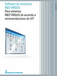
Interference in radiocommunications, e.g. at airports, not only impedes operation – it may even pose a threat to<br />
life.<br />
<strong>Rohde</strong> & <strong>Schwarz</strong> R&S®EB500 <strong>Monitoring</strong> <strong>Receiver</strong> 5
Comprehensive<br />
spectrum analysis<br />
with polychrome<br />
display<br />
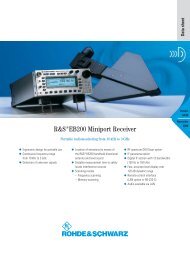
Polychrome display <strong>for</strong> detection and analysis of<br />
short-duration signals<br />
The polychrome IF spectrum color-codes the duration of a<br />
signal in the spectrum using multiple colors. Signals with<br />
a very short duration are displayed in blue while continuous<br />
signals appear in red. Overlapping short-duration and<br />
continuous signals in the spectrum can thus still be distinguished<br />
and displayed when this is no longer possible<br />
with conventional display modes such as max. hold and<br />
average.<br />
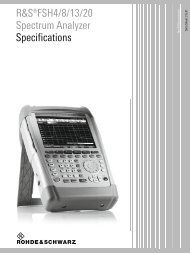
Polychrome IF spectrum: even signals with a low frequency of appearance<br />
are visible.<br />
Overlapping signals with the same frequency and timing are made visible<br />
using the polychrome spectrum.<br />
6
<strong>Monitoring</strong> of<br />
user-specific radio<br />
services<br />
The frequency scan mode is mainly intended <strong>for</strong><br />
monitoring radio services that use fixed channel<br />
spacing as compared to memory scan that is used<br />
<strong>for</strong> variable channel spacing.<br />
<strong>Monitoring</strong> of a large number of radio services<br />
with different scan modes<br />
In the frequency scan mode, a user-defined frequency<br />
range is scanned using fixed channel spacing. The receiver<br />
steps through the frequency range of interest and checks<br />
every channel <strong>for</strong> occupancy. If a signal is detected with<br />
a level exceeding the predefined threshold, the receiver<br />
dwells at the corresponding frequency <strong>for</strong> the set hold<br />
time, allowing <strong>for</strong> the signal to be demodulated and processed.<br />
In the case of analog modulation, the demodulated<br />
signal can be monitored via the headphones or<br />
loudspeaker.<br />
In the memory scan mode, predefined channels stored in<br />
memory locations are consecutively scanned and analyzed<br />
to see if any signals are present. The R&S®EB500 offers<br />
10 000 user-definable memory locations. Receive parameters<br />
can be assigned separately to each memory location.<br />
The memory scan mode is particularly useful <strong>for</strong> scanning<br />
individual frequencies that do not have a fixed channel<br />
spacing or that use different demodulation modes and<br />
bandwidths. The memory scan mode offers users a<br />
greater degree of freedom than the frequency scan mode<br />
in similar applications.<br />
Smooth operation of an organization’s own radio network is vital to ensure<br />
operational readiness — not only <strong>for</strong> government operators.<br />
<strong>Rohde</strong> & <strong>Schwarz</strong> R&S®EB500 <strong>Monitoring</strong> <strong>Receiver</strong> 7
Multichannel digital<br />
downconversion<br />
(DDC)<br />
Parallel monitoring and demodulation of<br />
one plus three signals within realtime bandwidth<br />
When equipped with the R&S®EB500-DDC digital<br />
downconverter option, the receiver has three additional<br />
digital downconverters in addition to the wideband demodulation<br />
path. These converters function entirely in parallel<br />
within the realtime bandwidth and can be parameterized<br />
independently of one another.<br />
Each of these digital downconverters features:<br />
❙❙AM, FM, PM, PULSE, I/Q, LSB, USB and CW<br />
demodulation mode<br />
❙❙Comprehensive set of 25 IF bandwidths from<br />
100 Hz to 1 MHz (100 Hz to 9 kHz <strong>for</strong> LSB, USB, CW)<br />
❙❙Automatic gain control (AGC)<br />
❙❙Squelch function<br />
Moreover, each DDC provides the complex baseband (I/Q),<br />
the associated signal level and an audio signal.<br />
The data streams output at the DDC channels can be<br />
either recorded internally in the receiver, or are available<br />
via LAN to be recorded by the remote control PC. Recording<br />
of four independent data streams is supported by the<br />
R&S®EB500-Control software package.<br />
Smooth one plus three demodulation channels can be user-distributed<br />
within the realtime bandwidth<br />
Control interface <strong>for</strong> managing of DDC in<strong>for</strong>mation output.<br />
8
Nationwide<br />
monitoring system<br />
<strong>for</strong> regulatory<br />
authorities<br />
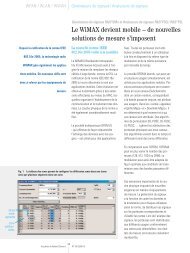
ITU-compliant spectrum monitoring using the<br />
R&S®ARGUS system software<br />
For more than 20 years, R&S®ARGUS has been a highly<br />
successful control software solution <strong>for</strong> ITU-compliant<br />
measurement and analysis tasks. It offers a variety of measuring<br />
modes designed to support typical measurement<br />
procedures and greatly simplify everyday tasks. It can also<br />
per<strong>for</strong>m a large number of analyses that enable detailed<br />
evaluation of measurements and the creation of precise,<br />
in-depth reports. These capabilities are now also available<br />
in combination with the R&S®EB500.<br />
Full access to receiver functions from a PC<br />
The user-friendly standard interface in R&S®ARGUS makes<br />
the entire range of R&S®EB500 functionality available on a<br />
PC. Measurement results are displayed in realtime in the<br />
<strong>for</strong>m of graphics and tables. The results are stored along<br />
with the receiver settings in an internal database to allow<br />
subsequent evaluation in line with ITU requirements.<br />
The entire system is calibrated, taking into account the<br />
frequency-dependent sensitivity of the antenna and<br />
attenuation and loss in cables and switches.<br />
Automatic identification of deviations from the<br />
desired state<br />
In combination with R&S®ARGUS, the R&S®EB500 can<br />
automatically identify whether the current signal scenario<br />
is consistent with expectations. Users can define a valid<br />
range of values <strong>for</strong> each measurement parameter depending<br />
on the frequency. If a measured value is outside the<br />
defined range, R&S®ARGUS immediately issues an alarm.<br />
New and unknown transmitters can thus be discovered<br />
just as easily as transmitters that exceed licensed broadcast<br />
parameters (e.g. excessive frequency deviation). This<br />
is especially important in connection with digitally modulated<br />
signals such as DAB and DVB-T. The implementation<br />
of vestigial sideband measurements in R&S®ARGUS in line<br />
with ITU recommendations (comparing the realtime signal<br />
against a spectrum mask) is particularly user-friendly (see<br />
figure).<br />
Guided measurements<br />
One unique feature in R&S®ARGUS are its guided measurement<br />
modes. Users simply choose a frequency range<br />
and the type of measurement task (field strength, spectrum<br />
occupancy or bandwidth, <strong>for</strong> example). R&S®ARGUS<br />
then configures the right device settings automatically and<br />
selects the appropriate antenna based on the frequency<br />
and polarization. This allows even relatively inexperienced<br />
users to conduct complex measurements with the<br />
R&S®EB500.<br />
Spectrum of a DVB-T transmitter with a mask overlay in line with<br />
ITU recommendations.<br />
<strong>Rohde</strong> & <strong>Schwarz</strong> R&S®EB500 <strong>Monitoring</strong> <strong>Receiver</strong> 9
Easy integration into existing R&S®ARGUS<br />
radiomonitoring systems<br />
The R&S®EB500 is quick and easy to integrate into existing<br />
infrastructures – as a replacement <strong>for</strong> existing equipment<br />
or to expand a station’s measurement capabilities.<br />
Importantly, the receiver can operate not just in combination<br />
and coordination with other equipment such as direction<br />
finders and specialized analysis devices but also as<br />
a hand-off receiver in a networked system. The ability to<br />
operate in parallel is not confined to the devices within a<br />
single radiomonitoring station: Multiple devices at separate<br />
stations can process several measurement tasks<br />
synchronously.<br />
Remote operation made easy<br />
Remote operability is a key requirement <strong>for</strong> radiomonitoring<br />
systems, and here, too, R&S®ARGUS sets standards.<br />
It has built-in sophisticated bandwidth management<br />
(SBM) that tunes the transmission rate to suit the available<br />
network bandwidth. If necessary, the software can<br />
reduce and compress data automatically. This ensures,<br />
<strong>for</strong> example, that the receiver’s IF spectrum and audio<br />
streams reach the central station in sufficiently high<br />
quality, even with narrowband connections.<br />
Station in<strong>for</strong>mation system (SIS) display<br />
Nationwide radiomonitoring network at a glance –<br />
R&S®ARGUS SIS<br />
Another advanced feature of R&S®ARGUS is its station in<strong>for</strong>mation<br />
system (SIS). The SIS shows the current status<br />
of every radiomonitoring system location on an electronic<br />
map. The in<strong>for</strong>mation provided includes the current connection<br />
status, the availability and utilization of measuring<br />
equipment, and ambient parameters such as t emperature,<br />
humidity and the power supply status in unattended<br />
radiomonitoring stations.<br />
UMS100-99992<br />
The map display also supports remote control features.<br />
When users click a symbol on the map, R&S®ARGUS<br />
automatically connects to the receiver in question. The<br />
R&S®EB500 in the remote station is then ready to accept<br />
measurement tasks.<br />
River police<br />
Headquarters at Munich airport<br />
(Germany)<br />
An example map showing a number of monitoring stations and their<br />
current status (indicated by different colors).<br />
10
Handoff receiver in<br />
networked systems<br />
Parallel demodulation of multiple narrowband<br />
signals and simultaneous broadband spectrum<br />
scanning<br />
Multiple R&S®EB500 devices can be combined with a fast<br />
and powerful search receiver (e.g. the R&S®ESMD) and<br />
operated as a system. The R&S®EB500 devices demodulate<br />
signals and produce audio or I/Q data streams, while<br />
the R&S®ESMD quickly searches <strong>for</strong> other signals with an<br />
extremely high level of sensitivity. A separate R&S®EB500<br />
is required <strong>for</strong> each signal that is to be processed in<br />
parallel.<br />
The handover of a signal from the R&S®ESMD to an<br />
R&S®EB500 is carried out from the user workstation running<br />
with R&S®RAMON system software. The major<br />
advantage of this system configuration is that the fast<br />
signal search across a wide frequency scenario and the<br />
narrowband production of multiple audio or I/Q data<br />
streams occur simultaneously. This allows the user to<br />
achieve optimum results in a minimum of time.<br />
Multiple R&S®EB500 devices can be operated together with<br />
an R&S®ESMD and operated as a system.<br />
Specifications in brief of the R&S®ESMD<br />
Frequency range<br />
Base unit<br />
20 MHz to 3.6 GHz<br />
HF option<br />
9 kHz to 32 MHz<br />
SHF option<br />
3.6 GHz to 26.5 GHz<br />
Linearity, third-order intercept, inband<br />
9 kHz to 32 MHz typ. 35 dBm (low distortion mode)<br />
20 MHz to 3.6 GHz typ. 25 dBm (low distortion mode)<br />
3.6 GHz to 26.5 GHz typ. 17 dB (attenuation > 0 dB)<br />
Noise figure<br />
400 kHz to 32 MHz typ. 12 dB (normal mode)<br />
20 MHz to 3.6 GHz typ. 9 dB (low noise mode)<br />
3.6 GHz to 26.5 GHz typ. 16 dB<br />
IF bandwidth<br />
Spectral path<br />
1 kHz to 20 MHz (80 MHz)<br />
Demodulation path<br />
100 Hz to 20 MHz (80 MHz <strong>for</strong> I/Q)<br />
Data interface<br />
1 Gbit LAN (Ethernet 1000BaseT)<br />
<strong>Rohde</strong> & <strong>Schwarz</strong> R&S®EB500 <strong>Monitoring</strong> <strong>Receiver</strong> 11
Convenient remote<br />
control with<br />
R&S®EB500‐Control<br />
software<br />
The R&S®EB500-Control remote control software<br />
is supplied free of charge with the R&S®EB500. It<br />
is part of the R&S®RAMON software family and<br />
enables convenient and efficient operation of the<br />
receiver from a PC workstation. The software offers<br />
a straight<strong>for</strong>ward menu structure and intuitive<br />
operation so that training requirements <strong>for</strong> operating<br />
personnel are minimal.<br />
Major functional features of R&S®EB500-Control<br />
Fast and simple operation<br />
The main functions can be accessed using shortcuts.<br />
The graphical display of results includes:<br />
❙❙IF spectrum with waterfall diagram<br />
❙❙Panorama scan spectrum with waterfall diagram<br />
❙❙Level indication based on demodulation path<br />
Users can adapt the colors of the display and the size and<br />
arrangement of the windows as required <strong>for</strong> a specific task<br />
or area of application. Easy-to-use measurement functions<br />
are available within the diagrams.<br />
Display, storage and playback of spectra and<br />
waterfall data<br />
R&S®EB500-Control enables the recording and playback<br />
of panorama scan and IF signal spectra. In addition, digital<br />
audio data and I/Q baseband data (digital IF) of up to<br />
5 MHz bandwidth can be stored, e.g. <strong>for</strong> the subsequent<br />
analysis of digitally modulated signals.<br />
Buffering of frequency scan data in a ring buffer<br />
Recording in the ring buffer can be stopped by a mouse<br />
click. The stored signals are then available in playback<br />
mode <strong>for</strong> analysis.<br />
Frequency list <strong>for</strong> marking signals<br />
With a mouse click, radio channels can be marked, saved<br />
in a list and graphically placed over the spectrum. The<br />
frequency list is available <strong>for</strong> storage and subsequent<br />
analysis.<br />
12
Display of IF spectrum and use of<br />
marker function.<br />
Wideband panorama scan with<br />
max. hold function and waterfall<br />
diagram.<br />
IF spectrum and waterfall diagram of<br />
a radar signal from Munich Airport<br />
( Germany).<br />
<strong>Rohde</strong> & <strong>Schwarz</strong> R&S®EB500 <strong>Monitoring</strong> <strong>Receiver</strong> 13
Precise direction<br />
finding of emissions<br />
(with R&S®EB500-<br />
DF direction finder<br />
upgrade kit)<br />
Fast, reliable direction finding due to high<br />
DF accuracy<br />
In the VHF/UHF range the R&S®EB500 with its direction<br />
finding function uses the correlative interferometer<br />
DF method. In contrast to simple amplitude comparison<br />
methods, the instrument there<strong>for</strong>e offers significantly<br />
higher, class A/B DF accuracy in line with ITU SMH 2002.<br />
This high DF accuracy relies on the precise measurement<br />
of the phase angles between the reference antenna element<br />
and the other elements. Measuring the phase difference<br />
between two signals normally requires two coherent<br />
receive paths. For this reason, most interferometer direction<br />
finders on the market use at least two receivers. In the<br />
R&S®EB500, the two receive paths are coherently linked<br />
in the DF antenna using a patented method. As a result,<br />
there is no need <strong>for</strong> a second interception processing<br />
channel that is customarily found in interferometer direction<br />
finders.<br />
In the HF range, the Watson-Watt direction finding<br />
method is used. The special advantage of this method is<br />
that small DF antennas can be deployed. Accordingly, the<br />
R&S®EB500 with its DF function is also very suitable <strong>for</strong><br />
mobile direction finding in this frequency range.<br />
Direction finding up to 6 GHz<br />
Together with the R&S®EB500-SHF option and the<br />
R&S®ADD075 UHF/SHF DF antenna, the R&S®EB500 delivers<br />
precise DF results up to 6 GHz. The compact instrument<br />
thus takes highly accurate bearings of signals above<br />
3 GHz such as:<br />
❙❙WLAN<br />
❙❙WiMAX<br />
❙❙Microwave links<br />
The DF function of the R&S®EB500 fully corresponds<br />
to that of the R&S®DDF205 digital direction finder<br />
(product brochure: PD 5214.3723.12, data sheet:<br />
PD 5214.3723.22).<br />
Display of DF results.<br />
14
Operating principle<br />
Frontend<br />
Signals are fed in via two separate antenna sockets. One<br />
of the sockets can be used <strong>for</strong> HF signals from 9 kHz to<br />
32 MHz, the other is a combined socket <strong>for</strong> HF/VHF/UHF<br />
signals from 9 kHz to 6 GHz. A switching system splits<br />
the input signals across three separate signal processing<br />
paths, based on frequency.<br />
Signals from 9 kHz to 32 MHz are routed directly to the<br />
A/D converter via an HF preselection block consisting of a<br />
tunable bandpass filter and a 32 MHz lowpass filter. Signals<br />
from 20 MHz to 650 MHz or from 650 MHz to 6 GHz<br />
are routed to the two-stage or three-stage IF section<br />
through the VHF/UHF preselection and a preamplifier (variable<br />
gain). The preselection and the low distortion mode<br />
effectively protect the IF sections against overloading.<br />
The two IF sections process the signals from 20 MHz to<br />
6 GHz <strong>for</strong> the subsequent A/D converter.<br />
Digital signal processing<br />
After A/D conversion of the signal (in each case, with a<br />
16-bit converter), the signal path is split up:<br />
In the first path, the IF spectrum is calculated using a digital<br />
downconverter (DDC), a digital filter and an FFT block.<br />
The bandwidth of the bandpass filter can be selected between<br />
1 kHz and 20 MHz. Be<strong>for</strong>e the IF spectrum is output<br />
via the LAN interface or on the display, results are postprocessed<br />
using the average, min. hold or max. hold function<br />
as selected by the user.<br />
In the second path, which also includes a DDC and digital<br />
filters, the signal is processed <strong>for</strong> level measurement or<br />
demodulation. To process the different signals with optimum<br />
signal-to-noise ratio, the receiver contains IF filters<br />
with demodulation bandwidths from 100 Hz to 20 MHz,<br />
which can be selected independently of the spectral IF<br />
bandwidth.<br />
Prior to the level measurement, the absolute value of the<br />
level is determined and weighted using the average, peak,<br />
RMS or fast (sample) function, as selected by the user.<br />
The measured level is then output on the display or via the<br />
LAN interface.<br />
To demodulate analog modulated signals, the complex<br />
baseband data passes through AM, FM, USB, LSB, ISB,<br />
pulse or CW demodulation stages after the bandpass filter<br />
and is subjected to automatic gain control (AGC) or<br />
manual gain control (MGC). After the AGC/MGC stage, the<br />
complex baseband data (up to 5 MHz of I/Q data) resulting<br />
from the digitally modulated signals is directly output <strong>for</strong><br />
further processing.<br />
The results obtained are available as digital data and can<br />
be output via the LAN interface as required <strong>for</strong> the particular<br />
task. Digital audio data is reconverted to analog signals<br />
<strong>for</strong> output via the headphone socket or loudspeaker.<br />
Block diagram of frontend<br />
HF input<br />
HF preselection filter bank<br />
Lowpass filter<br />
9 kHz to 32 MHz<br />
32 MHz<br />
to HF<br />
A/D converter<br />
HF/<br />
VHF/UHF<br />
input<br />
20 MHz to<br />
650 MHz<br />
Highpass filter<br />
20 MHz<br />
Preselection<br />
filter bank<br />
Variable preamplifier<br />
Lowpass filter<br />
650 MHz<br />
2-stage<br />
super-het<br />
receiver<br />
650 MHz to 6 GHz<br />
Highpass filter<br />
650 MHz<br />
Preselection<br />
filter bank<br />
Variable preamplifier<br />
Lowpass filter<br />
8 GHz<br />
3-stage<br />
super-het<br />
receiver<br />
57.4 MHz<br />
IF3 to<br />
A/D converter<br />
<strong>Rohde</strong> & <strong>Schwarz</strong> R&S®EB500 <strong>Monitoring</strong> <strong>Receiver</strong> 15
Analog signals are reconverted from the I/Q data by a<br />
16 bit D/A converter; they are then available as analog<br />
IF signals or analog video data.<br />
High receiver sensitivity, high signal resolution<br />
The R&S®EB500 features an IF bandwidth of up to<br />
20 MHz. This allows even very short signal pulses to be<br />
captured since the receiver displays the wide bandwidth<br />
of 20 MHz in a single spectrum around the set center frequency<br />
without any scanning being required.<br />
Using the AUTO setting, the widest IF bandwidth of<br />
20 MHz yields the widest spectral display; the narrowest<br />
IF bandwidth of 1 kHz yields maximum sensitivity and<br />
resolution.<br />
The receiver’s IF spectrum is digitally calculated using Fast<br />
Fourier Trans<strong>for</strong>m (FFT). The use of FFT computation at the<br />
IF offers a major advantage: The receiver sensitivity and<br />
signal resolution are clearly superior to those of a conventional<br />
analog receiver at the same spectral display width.<br />
IF spectrum<br />
FFT calculation of the IF spectrum is per<strong>for</strong>med in a number<br />
of steps. These are described below in simplified <strong>for</strong>m<br />
<strong>for</strong> an IF bandwidth of 20 MHz ( BW IF spectrum<br />
= 20 MHz),<br />
which yields high spectral display.<br />
Due to the finite edge steepness of the IF filter, the sampling<br />
rate f S<br />
must be larger than the selected IF bandwidth<br />
BW IF spectrum<br />
. The quotient of the sampling rate and the<br />
IF bandwidth is thus a value > 1 and is a measure of the<br />
edge steepness of the IF filter. This relationship is expressed<br />
by the following two <strong>for</strong>mulas (<strong>for</strong> the AUTO<br />
setting):<br />
or<br />
f s<br />
= const<br />
BW IF spectrum<br />
f S<br />
= BW IF spectrum<br />
× const<br />
The value of the constant is dependent on the selected<br />
IF bandwidth, i.e. it may vary as a function of the IF<br />
bandwidth.<br />
Block diagram of digital signal processing<br />
Clear/write<br />
HF direct<br />
16 bit<br />
A<br />
D<br />
IF panorama<br />
path<br />
DDC<br />
IF spectrum<br />
1 kHz to 20 MHz<br />
FFT<br />
4096 points<br />
Average<br />
Min.<br />
hold<br />
Max.<br />
hold<br />
Display and LAN<br />
IF spectrum<br />
3 IF<br />
A<br />
D<br />
16 bit<br />
Demodulation<br />
path<br />
DDC<br />
Demodulation<br />
bandwidths<br />
100 Hz to 5 MHz<br />
ABS<br />
value<br />
Fast<br />
Average<br />
RMS<br />
Level<br />
measurement<br />
ITU<br />
measurement<br />
Display and LAN<br />
Peak<br />
Video spectrum<br />
Lowpass filter<br />
Analog audio<br />
Video/IF<br />
analog output<br />
A<br />
D<br />
16 bit<br />
Digital upconverter<br />
Demod<br />
AGC<br />
MGC<br />
Digital audio<br />
via LAN<br />
I/Q data<br />
via LAN<br />
16
For an IF bandwidth of BW IF spectrum<br />
= 20 MHz, the constant<br />
has a value of 1.28. There<strong>for</strong>e, to display a 20 MHz<br />
IF spectrum, a sampling rate of f S<br />
= 25.6 MHz is required.<br />
The R&S®EB500 uses a maximum FFT length N of<br />
4096 points to generate the IF spectrum. To calculate<br />
these points, the 25.6 MHz sampling band in the above<br />
example is divided into 4096 equidistant frequency slices,<br />
which are also referred to as bins (see figure “Signal<br />
processing <strong>for</strong> IF spectrum”).<br />
The bandwidth BW bin<br />
of the frequency slices is obtained as<br />
follows:<br />
BW Bin<br />
f s<br />
25.6 MHz<br />
= =<br />
= 6.25 kHz<br />
4096 4096<br />
This means that in the above example only the calculated<br />
bandwidth of 6.25 kHz <strong>for</strong> each bin has to be taken into<br />
account as the noise bandwidth in the calculation of the<br />
displayed noise level (DNL) in accordance with the <strong>for</strong>mula<br />
below (the effect of the window function (Blackman<br />
window) of the FFT is not considered here <strong>for</strong> simplicity’s<br />
sake):<br />
DNL = –174 dBm + NF + 10 × log(BW bin<br />
/Hz)<br />
The quantity NF represents the overall noise figure of the<br />
receiver.<br />
The above example shows that, due to the use of the FFT,<br />
the actual resolution bandwidth (RBW) to be taken into account<br />
in DNL calculation is clearly smaller (i.e. BW bin<br />
) than<br />
would be expected <strong>for</strong> the wide (unscanned) display range<br />
of 20 MHz.<br />
Another advantage of the high spectral resolution used in<br />
the FFT calculation is that signals located close together<br />
(e.g. f 1<br />
, f 2<br />
and f 3<br />
) can be captured and represented in the<br />
IF spectrum as discrete signals (see figure “Signal display<br />
in IF spectrum”).<br />
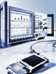
Signal processing <strong>for</strong> IF spectrum<br />
a in dBµV<br />
If, on an analog receiver, a resolution bandwidth equal to<br />
the set IF bandwidth were selected (RBW = BW IF spectrum<br />
),<br />
a sum signal f sum<br />
would be displayed instead of the three<br />
discrete signals f 1<br />
, f 2<br />
and f 3<br />
.<br />
n = 1 n = 4096<br />
f RX<br />
20 MHz<br />
25.6 MHz<br />
Frequency in MHz<br />
Actual sampling bandwidth compared with selected IF bandwidth.<br />
Signal display in IF spectrum<br />
a<br />
Input signal<br />
IF spectrum<br />
a<br />
a<br />
Input signal<br />
IF spectrum<br />
a<br />
IF<br />
bandwidth<br />
f 1<br />
f 2<br />
f 3<br />
f<br />
f 1<br />
f 2<br />
f 3<br />
f<br />
IF<br />
bandwidth<br />
Analog Digital<br />
f 1<br />
f 2<br />
f 3<br />
f<br />
f sum<br />
f<br />
Signal resolution in IF spectrum in digital and analog receiver concept.<br />
<strong>Rohde</strong> & <strong>Schwarz</strong> R&S®EB500 <strong>Monitoring</strong> <strong>Receiver</strong> 17
The realtime signal processing at the IF level also includes<br />
other high-per<strong>for</strong>mance capabilities, such as overlapping<br />
FFT <strong>for</strong> the optimum capture of pulsed signals and a configurable<br />
bin width <strong>for</strong> adjusting to the channel spacing<br />
of known radio services. These functions are described in<br />
detail in the user manual.<br />
Panorama scan<br />
The receiver’s maximum FFT bandwidth of 20 MHz makes<br />
it possible to per<strong>for</strong>m extremely fast scans across a wide<br />
frequency range (panorama scan). For this purpose, frequency<br />
windows of max. 20 MHz width are linked in succession,<br />
so that the complete, predefined scan range is<br />
traversed (see figure “Signal processing in panorama scan<br />
mode”). As is done <strong>for</strong> the IF spectrum, an FFT is used to<br />
process the broad window with a finer resolution.<br />
The width of the frequency window and the FFT length<br />
(number of FFT points) are variable and are selected by the<br />
receiver.<br />
In the panorama scan mode, the user can select among 24<br />
resolution bandwidths from 100 Hz to 2 MHz. The resolution<br />
bandwidth corresponds to the width of the frequency<br />
slices (bin width) mentioned under “IF spectrum”. Based<br />
on the selected bin width and start and stop frequency,<br />
the R&S®EB500 automatically determines the required FFT<br />
length and the width of the frequency window <strong>for</strong> each<br />
scan step. The receiver selects these internal parameters<br />
so that the optimum scan speed is achieved <strong>for</strong> each resolution<br />
bandwidth (see figure “Resolution in panorama scan<br />
mode”).<br />
In the panorama scan mode, the resolution bandwidth of<br />
2 MHz yields the maximum scan speed, while the resolution<br />
bandwidth of 100 Hz yields maximum sensitivity.<br />
The resolution bandwidth (bin width) <strong>for</strong> the panorama<br />
scan (selectable between 100 Hz and 2 MHz) there<strong>for</strong>e<br />
corresponds to the resolution bandwidth (BW bin<br />
) used in<br />
the DNL calculation <strong>for</strong> the IF spectrum (see DNL <strong>for</strong>mula<br />
under “IF spectrum”), and can be used <strong>for</strong> calculating the<br />
DNL <strong>for</strong> the panorama scan. Moreover, the user selects<br />
the resolution bandwidth to obtain the desired frequency<br />
resolution (see figure “Bin width and channel spacing”).<br />
The above explanations show that the use of digital signal<br />
processing in a radiomonitoring receiver offers decisive<br />
advantages. Extremely high sensitivity (due to very fine<br />
resolution) combined with a broad spectral overview and<br />
maximum scan speed significantly increases the probability<br />
of intercept in comparison with an analog receiver.<br />
Signal processing in panorama scan mode<br />
a in dBµV<br />
max. 20 MHz<br />
FFT window 1 FFT window 2<br />
n=1 n = X<br />
FFT window n<br />
f start<br />
f stop<br />
Frequency in MHz<br />
Basic sequence of steps in fast panorama scan mode.<br />
Resolution in panorama scan mode<br />
Bin width and channel spacing<br />
a in dBµV<br />
n = 1<br />
max. 20 MHz<br />
n = X<br />
a in dBµV<br />
Points <strong>for</strong> FFT calculation<br />
Bin<br />
width<br />
Channel<br />
spacing<br />
Bin width:<br />
min. 100 Hz<br />
max. 2 MHz<br />
Frequency in MHz<br />
f1<br />
f2<br />
Signal frequencies<br />
Frequency in MHz<br />
Selecting the panorama scan resolution by varying the bin width.<br />
Selecting a 12.5 kHz bin width to capture a radio service using 12.5 kHz<br />
channel spacing.<br />
18
Specifications in brief<br />
Specifications in brief<br />
Frequency<br />
Frequency range base unit 20 MHz to 3.6 GHz<br />
with R&S®EB500-HF option<br />
9 kHz to 3.6 GHz<br />
with R&S®EB500-FE option<br />
20 MHz to 6 GHz<br />
with R&S®EB500-HF and R&S®EB500-FE options 9 kHz to 6 GHz<br />
Demodulation<br />
Demodulation modes all IF bandwidths AM, FM, PM, PULSE, I/Q<br />
IF bandwidths ≤ 9 kHz<br />
LSB, USB, CW<br />
IF bandwidths ≥ 1 kHz<br />
ISB<br />
IF bandwidths<br />
Bandwidth<br />
demodulation, level and offset measurements<br />
(3 dB bandwidth), 34 filters<br />
100/150/300/600 Hz,<br />
1/1.5/2.1/2.4/2.7/3.1/4/4.8/6/9/12/15/30/50/<br />
120/150/250/300/500/800 kHz,<br />
1/1.25/1.5/2/5/8/10/12.5/15/20 MHz<br />
IF panorama<br />
FFT IF panorama up to 4096-point FFT dynamic, overlapping FFT<br />
operating modes<br />
automatic or variable with selectable frequency<br />
resolution<br />
0.625/1.25/2.5/3.125/6.25/12.5/25/31.25/50/62.5/<br />
100/125/200/250/312.5/500/625 Hz,<br />
1/1.25/2/2.5/3.125/5/6.25/8.333/10/12.5/20/<br />
25/50/100/200/500 kHz, 1 MHz, 2 MHz<br />
IF panorama span<br />
1/2/5/10/20/50/100/200/500 kHz,<br />
1/2/5/10/20 MHz<br />
Panorama display<br />
clear/write, average, max. hold, min. hold<br />
DF mode VHF/UHF/SHF range correlative interferometer<br />
HF range<br />
Watson-Watt<br />
Scan characteristics<br />
Memory scan<br />
10000 programmable memory locations<br />
speed<br />
up to 500 channels/s<br />
Frequency scan<br />
user-selectable start/stop frequency and step<br />
width<br />
speed<br />
up to 500 channels/s<br />
Panorama scan with R&S®EB500-PS option RF spectrum with user-selectable start/stop<br />
frequency and step width:<br />
100/125/200/250/500/625 Hz,<br />
1/1.25/2/2.5/3.125/5/6.25/8.333/10/12.5/20/<br />
25/50/100/200/500 kHz, 1 MHz, 2 MHz<br />
speed<br />
up to 12 GHz/s<br />
For data sheet, see PD 5214.3800.22 and www.rohde-schwarz.com.<br />
<strong>Rohde</strong> & <strong>Schwarz</strong> R&S®EB500 <strong>Monitoring</strong> <strong>Receiver</strong> 19
Ordering in<strong>for</strong>mation<br />
Designation Type, description Order No.<br />
<strong>Monitoring</strong> <strong>Receiver</strong>, with control front panel R&S®EB500 4072.5004.03<br />
frequency range from 20 MHz to 3.6 GHz, IF spectrum<br />
(max. 20 MHz), remote control software supplied with<br />
receiver<br />
<strong>Monitoring</strong> <strong>Receiver</strong>, without control front panel R&S®EB500 4072.5004.02<br />
frequency range from 20 MHz to 3.6 GHz, IF spectrum<br />
(max. 20 MHz), remote control software supplied with<br />
receiver<br />
Hardware options<br />
HF Frequency Range Extension R&S®EB500-HF 4072.8003.02<br />
frequency range from 9 kHz to 32 MHz<br />
Software options<br />
SHF Frequency Range Extension R&S®EB500-FE 4072.9300.02<br />
frequency range from 3.6 GHz to 6 GHz<br />
Panorama Scan R&S®EB500-PS 4072.9200.02<br />
RF scan, high-speed FFT scan across user-selectable<br />
range, selectable spectral resolution<br />
ITU Measurement R&S®EB500-IM 4072.9100.02<br />
ITU-compliant measurement of AM/FM-modulated signals<br />
in the R&S®EB500<br />
Digital Downconverter R&S®EB500-DDC 4072.9500.02<br />
three digital downconverters <strong>for</strong> user-defined placement<br />
within realtime bandwidth<br />
Direction Finder Upgrade Kit R&S®EB500-DF 4072.9400.02<br />
precise direction finding integrated in R&S®EB500<br />
Wideband Direction Finding R&S®EB500-WDF 4072.9651.02<br />
<strong>for</strong> parallel direction finding of all emitters within realtime<br />
bandwidth<br />
DF Error Correction R&S®EB500-COR 4072.9600.02<br />
Selective Call R&S®EB500-SL 4072.9800.02<br />
selective call analysis<br />
Software Package in line with ITU-R SM.1600<br />
(<strong>for</strong> ITU-compliant measurement of analog and<br />
digitally modulated signals)<br />
Accessories<br />
R&S®GX430IS<br />
(R&S®GX430 required <strong>for</strong> using R&S®GX430IS with<br />
R&S®EB500)<br />
4071.5817.02<br />
19" Rack Adapter R&S®ZZA-T04 1109.4187.00<br />
<strong>for</strong> mounting two R&S®EB500 in a 19" rack (both receivers<br />
side by side)<br />
19" Rack Adapter R&S®ZZA-T02 1109.4164.00<br />
<strong>for</strong> mounting one R&S®EB500 in a 19" rack (including one<br />
blind plate)<br />
DC Power Cable R&S®EB500-DCC 4072.7036.00<br />
DF antennas<br />
HF DF Antenna R&S®ADD119 4053.6509.02<br />
VHF/UHF DF Antenna R&S®ADD196 4077.3000.02<br />
Dual Polarized VHF/UHF DF Antenna R&S®ADD197 4068.1450.02<br />
Broadband VHF/UHF DF Antenna R&S®ADD295 4070.9002.12<br />
UHF DF Antenna R&S®ADD175 4079.4003.02<br />
UHF DF Antenna R&S®ADD071 4043.6006.02<br />
UHF/SHF DF Antenna R&S®ADD075 4069.6603.02<br />
System components<br />
For cables, antenna adapters, mast adapters, tripods, etc., see R&S®DDF205 data sheet (PD 5214.3723.22).<br />
Calibration documenting<br />
Documentation of Calibration Values R&S®EB500-DCV 4072.8403.02<br />
<strong>Rohde</strong> & <strong>Schwarz</strong> R&S®EB500 <strong>Monitoring</strong> <strong>Receiver</strong> 20
Service options<br />
Extended Warranty, one year R&S®WE1EB500 Please contact your local<br />
Extended Warranty, two years<br />
R&S®WE2EB500<br />
<strong>Rohde</strong> & <strong>Schwarz</strong> sales office.<br />
Extended Warranty, three years<br />
Extended Warranty, four years<br />
Extended Warranty with Calibration Coverage, one year<br />
Extended Warranty with Calibration Coverage, two years<br />
Extended Warranty with Calibration Coverage, three years<br />
Extended Warranty with Calibration Coverage, four years<br />
R&S®WE3EB500<br />
R&S®WE4EB500<br />
R&S®CW1EB500<br />
R&S®CW2EB500<br />
R&S®CW3EB500<br />
R&S®CW4EB500<br />
Your local <strong>Rohde</strong> & <strong>Schwarz</strong> expert will help you determine the optimum solution <strong>for</strong> your requirements.<br />
To find your nearest <strong>Rohde</strong> & <strong>Schwarz</strong> representative, visit<br />
www.sales.rohde-schwarz.com<br />
Rear view of the R&S®EB500. The power<br />
supply input, LAN interface and additional<br />
AUX interfaces are accessible from the rear<br />
<strong>for</strong> optimal rack installation.<br />
<strong>Rohde</strong> & <strong>Schwarz</strong> R&S®EB500 <strong>Monitoring</strong> <strong>Receiver</strong> 21
Service you can rely on<br />
❙ Worldwide<br />
❙ Local and personalized<br />
❙ Customized and flexible<br />
❙ Uncompromising quality<br />
❙ Long-term dependability<br />
About <strong>Rohde</strong> & <strong>Schwarz</strong><br />
<strong>Rohde</strong> & <strong>Schwarz</strong> is an independent group of companies<br />
specializing in electronics. It is a leading supplier of solutions<br />
in the fields of test and measurement, broadcasting,<br />
radiomonitoring and radiolocation, as well as secure<br />
communications. Established more than 75 years ago,<br />
<strong>Rohde</strong> & <strong>Schwarz</strong> has a global presence and a dedicated<br />
service network in over 70 countries. Company headquarters<br />
are in Munich, Germany.<br />
Environmental commitment<br />
❙❙Energy-efficient products<br />
❙❙Continuous improvement in environmental sustainability<br />
Certified Quality System<br />
ISO 9001<br />
<strong>Rohde</strong> & <strong>Schwarz</strong> GmbH & Co. KG<br />
www.rohde-schwarz.com<br />
Regional contact<br />
❙❙Europe, Africa, Middle East | +49 89 4129 12345<br />
customersupport@rohde-schwarz.com<br />
❙❙North America | 1 888 TEST RSA (1 888 837 87 72)<br />
customer.support@rsa.rohde-schwarz.com<br />
❙❙Latin America | +1 410 910 79 88<br />
customersupport.la@rohde-schwarz.com<br />
❙❙Asia/Pacific | +65 65 13 04 88<br />
customersupport.asia@rohde-schwarz.com<br />
❙❙China | +86 800 810 8228/+86 400 650 5896<br />
customersupport.china@rohde-schwarz.com<br />
R&S® is a registered trademark of <strong>Rohde</strong> & <strong>Schwarz</strong> GmbH & Co. KG<br />
Trade names are trademarks of the owners | Printed in Germany (sk)<br />
PD 5214.3800.12 | Version 03.01 | July 2012 | R&S®EB500<br />
Data without tolerance limits is not binding | Subject to change<br />
© 2010 - 2012 <strong>Rohde</strong> & <strong>Schwarz</strong> GmbH & Co. KG | 81671 München, Germany<br />
5214380012