Contents List of Figures List of tables - Porkka
Contents List of Figures List of tables - Porkka
Contents List of Figures List of tables - Porkka

You also want an ePaper? Increase the reach of your titles
YUMPU automatically turns print PDFs into web optimized ePapers that Google loves.
en<br />
en<br />
User manual<br />
PAROS<br />
1. UNLOADING<br />
The device should be transported in vertical position, and it should be properly secured and packed. The manufacturer<br />
ships the device on a special wooden platform, secured with cardboard angle sections and foil.<br />
2. PROPERTIES OF THE DEVICE<br />
2.1. Purpose<br />
“Paros” is a universal cooling device aimed for storing and displaying a vast range <strong>of</strong> grocery products previously cooled<br />
to storing temperature. Guaranteed temperature inside the display cabinet equals +2ºC/+8ºC with ambient temperature <strong>of</strong><br />
+15ºC/+25ºC and relative air humidity <strong>of</strong> up to 60%.<br />
2.2. Description <strong>of</strong> the device<br />
“Paros” display racks have dynamic cooling. All types <strong>of</strong> devices are furnished with automatic defrosting and electronic<br />
thermostat optionally cooperating with temperature recording module enabling to record and signal too low and too high<br />
temperature within the device. There also is an option with automatic condensate evaporation. They are adjusted and can<br />
be connected in sequences in the version with internal aggregate (mod/A) and to be mounted on central aggregate (mod/C).<br />
Racks are equipped with 4 or 5 display shelves (depending on the type <strong>of</strong> the device), with the possibility to change<br />
their height and angle. It is possible to order meat hooks, as well as fruit and vegetable baskets. The interior <strong>of</strong> the rack<br />
is illuminated. It is also possible to place additional illumination <strong>of</strong> each shelf. Our devices are made according to modern<br />
technologies and have all certificates required by law.<br />
<strong>Contents</strong><br />
1. UNLOADING 12<br />
2. PROPERTIES OF THE DEVICE 12<br />
2.1. Purpose 12<br />
2.2. Description <strong>of</strong> the device 12<br />
2.3. Technical data 14<br />
3. PREPARING THE DEVICE FOR EXPLOITATION 14<br />
3.1. Requirements concerning the place <strong>of</strong> installation 14<br />
3.2. Connection and actuation 14<br />
4. EXPLOITATION 17<br />
4.1. Temperature regulation 17<br />
5. MAINTENANCE 17<br />
5.1. Cleaning and maintenance 17<br />
6. SERVICE 19<br />
6.1. Fault identification and repair 19<br />
6.2. Service 20<br />
7. THERMOSTAT SERVICE 21<br />
7.1. „IGLOO” thermostat 21<br />
7.2. „CAREL” thermostat 22<br />
<strong>List</strong> <strong>of</strong> <strong>Figures</strong><br />
Fig.1 Construction <strong>of</strong> the device with internal aggregate 13<br />
Fig.2 Construction <strong>of</strong> the device to be mounted on central<br />
aggregate 13<br />
Fig.3 Removing the wooden platform 15<br />
Fig.4 Fixing the hook in the frame 15<br />
Fig.5 Rack shelf set 16<br />
Fig.6 Meat hooks rail 16<br />
Fig.7 Fruit and vegetable baskets 16<br />
Fig.8 Control panel 16<br />
Fig.9 Condensate container 18<br />
Fig.10 Cleaning the condenser 18<br />
Fig.11 Changing the fl uorescent lamp 18<br />
Fig.12 Assembly/disassembly <strong>of</strong> the glass side 19<br />
Fig.13 Data plate 20<br />
Fig.14 „Igloo” thermostat control panel 21<br />
Fig.15 „Carel” thermostat control panel 22<br />
<strong>List</strong> <strong>of</strong> <strong>tables</strong><br />
Table 1 Technical data 14<br />
This sign signifies information <strong>of</strong> particular meaning for user security and for proper device<br />
exploitation.<br />
12 User manual Paros www.igloo.pl
en<br />
Fig.1 Construction <strong>of</strong> the device with internal aggregate<br />
1<br />
2<br />
5<br />
13<br />
6<br />
4<br />
3<br />
14<br />
7<br />
15<br />
8<br />
16<br />
9<br />
10<br />
11<br />
19<br />
12<br />
17<br />
18<br />
Fig.2 Construction <strong>of</strong> the device to be mounted on central aggregate<br />
1<br />
2<br />
17<br />
13<br />
14<br />
4<br />
3<br />
6<br />
9<br />
10<br />
11<br />
12<br />
16<br />
www.igloo.pl<br />
User manual Paros<br />
13
en<br />
1 – Manual roller blind<br />
2 – Lighting <strong>of</strong> the upper panel<br />
3 – Upper panel plexiglas<br />
4 – Upper lighting - internal<br />
5 – Meat hooks (optional)<br />
6 – Display shelf – possibility to change height and<br />
angle<br />
7 – Fruit and vegetable basket (optional)<br />
8 – Front fender beam<br />
9 – Front panel<br />
10 – Basis <strong>of</strong> the rack<br />
11 – Wooden platform fixed for transport <strong>of</strong> the device<br />
12 – Device levelling feet<br />
13 – Data plate<br />
14 – ABS sides with glass<br />
15 – Rack screen (DO NOT BLOCK VENTILATION<br />
HOLES ensuring circulation <strong>of</strong> the cooled air!!!)<br />
16 – Roller handle<br />
17 – Control panel (temperature regulator/switches)<br />
18 – Wind brace (after removing – access to condenser<br />
<strong>of</strong> the lamellas) – DO NOT BLOCK THE<br />
HOLES!!!)<br />
19 – Condensate masking frame<br />
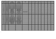
2.3. Technical data<br />
Table 1 Technical data<br />
Type <strong>of</strong> the<br />
device “PAROS”<br />
Rated<br />
voltage<br />
[V/Hz]<br />
Rated<br />
current [A]<br />
Rated<br />
lighting<br />
power<br />
[W]<br />
Electric<br />
energy<br />
consumption<br />
[kWh/24h]<br />
Cooling<br />
power<br />
demand<br />
[W/mb]<br />
Max shelf<br />
load<br />
[kg/mb]<br />
Weight <strong>of</strong><br />
the device<br />
[kg]<br />
1.0 230/50 2,9 60 9,3 x 33 150<br />
1.3 230/50 3,9 72 12,5 x 33 180<br />
1.6 230/50 5,3 116 17,2 x 33 210<br />
1.9 230/50 6,6 120 21,3 x 33 250<br />
2.5 230/50 6,8 144 22,0 x 33 290<br />
1.0 - mod/A 230/50 2,9 60 9,3 x 33 130<br />
1.3 - mod/A 230/50 3,9 72 12,5 x 33 160<br />
1.6 - mod/A 230/50 5,3 116 17,2 x 33 190<br />
1.9 - mod/A 230/50 6,6 120 21,3 x 33 230<br />
2.5 - mod/A 230/50 6,8 144 22,0 x 33 270<br />
1.0 - mod/C 230/50 0,5 60 1,5 800 33 115<br />
1.3 - mod/C 230/50 0,5 72 1,6 800 33 145<br />
1.6 - mod/C 230/50 0,8 116 2,5 800 33 175<br />
1.9 - mod/C 230/50 0,9 120 2,9 800 33 215<br />
2.5 - mod/C 230/50 1,0 144 3,2 800 33 255<br />
Rated lighting power in devices with illuminates shelves is greater than the one stated in the<br />
table!<br />
3. PREPARING THE DEVICE FOR EXPLOITATION<br />
3.1. Requirements concerning the place <strong>of</strong> installation<br />
• Verify whether the cross section <strong>of</strong> feeding conduits is proper for power consumption <strong>of</strong> the installed device.<br />
• It is forbidden to connect the device by extension rods or dividers.<br />
• The device should be connected to the separate, properly made electric circuit with plug-in socket with<br />
protecting pin (according to PBUE /Regulations concerning Electric Equipment Construction/)<br />
The device may be actuated solely after confi rmation <strong>of</strong> the fi re protection effi ciency with results <strong>of</strong><br />
measures performed according to binding regulations!<br />
3.2. Connection and actuation<br />
• Unpack the device and remove the wooden platform from the basis Fig.3 (p.15)<br />
• The device should be placed on an even and on a suffi ciently hard base, and then level it with the help<br />
<strong>of</strong> levelling feet.<br />
14 User manual Paros www.igloo.pl
en<br />
• Remove the protection foil from the elements <strong>of</strong> the device (f. ex. from the inside <strong>of</strong> the device, display shelves,<br />
front fender beam)<br />
• If the user shall obtain a device partially disassembled to secure it during transportation, perform the following<br />
operations:<br />
1. Fix hooks in frame rails Fig.4 (p.15)<br />
2. Place shelves and/or baskets on hooks Fig.5 (p.16) and/or Fig.7 (p.16)<br />
3. (Concerns the devices with internal aggregate) Place the condensate container on the basis <strong>of</strong> the aggregate,<br />
under water outfl ow hose (does not concern devices with automatic condensate evaporation) Fig.9 (p.18)<br />
4. (Concerns the devices to be mounted on central aggregate) Defrosting water outfl ow is located under the<br />
bottom <strong>of</strong> the body (about 10mm from the back <strong>of</strong> the rack, in the middle part <strong>of</strong> the body), which needs to<br />
allow water outfl ow to the sewage grit.<br />
• The fi rst cleaning <strong>of</strong> the device should be provide right after unpacking, and before turning it on. The unit should<br />
be cleaned with water at a temperature not exceeding 40°C with a neutral detergent. For washing and cleaning<br />
the equipment it is prohibited to use products containing chlorine and sodium varieties, which destroy the protective<br />
layer and components <strong>of</strong> the device! Any residue <strong>of</strong> adhesives or silicone on metal elements should be removed<br />
only with extraction naphtha (not applicable to items made <strong>of</strong> plastic !). Do not use other organic solvents.<br />
When cleaning the unit is prohibited to use water jet. The unit should be cleaned with a wet rag.<br />
After installation <strong>of</strong> the device at the destination place it should be left to rest for at least 2 hours before<br />
turning it on (for devices with built in compressor) to set the level <strong>of</strong> refrigerant in order to prevent problems<br />
with starting up the aggregate.<br />
WARNING: Keep out the cooling circuit from damage!<br />
• Place the plug <strong>of</strong> the connecting cable directly in plug-in socket (it is forbidden to connect the device by means<br />
<strong>of</strong> extension cords or dividers!)<br />
• Turn on the main switch Fig.8/2 (p.16), which activates the thermostat, and then aggregate <strong>of</strong> the device<br />
• Set the temperature on thermostat control panel Fig.8/1 (p.16) (thermostat service details on p.21 or 22)<br />
• Turn on the lighting switch Fig.8/3 (p.16)<br />
1 2 3<br />
Fig.3 Removing the wooden platform<br />
1 – Unscrew the feet from the platform<br />
2 – Remove the wooden platform<br />
3 – Screw the feet in nuts welded to the frame <strong>of</strong> the device<br />
Fig.4 Fixing the hook in the frame<br />
1 – Rack screen<br />
2 – Hook fi xing frame<br />
3 – Hook (adjusted to three level<br />
angle regulation)<br />
1<br />
2 3<br />
www.igloo.pl<br />
User manual Paros<br />
15
en<br />
3<br />
6 1<br />
2<br />
Fig.5 Rack shelf set<br />
1 – Shelf hook<br />
2 – Element securing the shelf<br />
against shifting<br />
3 – Rack shelf<br />
4 – Cool air steering wheel<br />
5 – Shelf price strip<br />
6 – Shelf limiter<br />
5<br />
4<br />
1<br />
2 3<br />
Fig.6 Meat hooks rail<br />
1 – Hook under the meat hook rail<br />
2 – Meat hook rail<br />
3 – Meat hooks<br />
2<br />
1<br />
2<br />
3<br />
1<br />
Fig.7 Fruit and vegetable<br />
baskets<br />
1 – Basket hook<br />
2 – Fruit and vegetable basket<br />
3 – 20x20x2 closed steel pr<strong>of</strong>i le<br />
connecting baskets (concerns<br />
racks 1.3 and 2.5)<br />
1<br />
2 3<br />
Fig.8 Control panel<br />
1 – Thermostat (temperature regulator) panel<br />
(service details in Chapter No. 7 p.21 or 22)<br />
2 – Main switch (turns on/<strong>of</strong>f the aggregate <strong>of</strong> the device)<br />
3 – Lighting switch<br />
16 User manual Paros www.igloo.pl
en<br />
4. EXPLOITATION<br />
Temperature <strong>of</strong> the cooled space and aggregate operating cycle may fluctuate. They depend on numerous factors,<br />
such as amount and temperature <strong>of</strong> products placed in the device and temperature <strong>of</strong> the surroundings.<br />
The device should be placed in a dry and well-ventilated place, ensuring proper air exchange (distance between the<br />
wall and the device – min. 10 cm), out <strong>of</strong> sunlight, kept far from heat sources and devices enforcing air flow (ceiling<br />
and portable ventilators, blow-in heaters). The device functions properly in a room, where temperature falls within<br />
appropriate climatic class stated on the data plate. The operation <strong>of</strong> the device may worsen when it shall operate in<br />
temperature lower or higher than the stated temperature range.<br />
Remarks and indications<br />
• It is necessary to properly level the rack, which will prevent the device from noisy operation and will ensure<br />
proper outflow <strong>of</strong> the water (condensate) during defrosting.<br />
• After transporting the device, wait about 2 hours before its actuation.<br />
• In order to ensure proper conditions for the stored products, do not load the shelves completely. It is necessary<br />
to ensure even load <strong>of</strong> shelves and not to exceed the maximum load.<br />
• The first filling <strong>of</strong> cooling space should be performed after its previous cooling to working temperature. This<br />
principle should also be observed after longer pause in exploitation.<br />
• Do not block any ventilation holes, which would hamper circulation <strong>of</strong> the cooled air (Do not place the<br />
products directly to the screen!). It is also necessary to ensure proper airflow around the device (aggregate<br />
ventilation holes cannot be covered).<br />
• Keep the condenser clean. Impurities may lead to overheating <strong>of</strong> the compressor and as a consequence<br />
may result in damage <strong>of</strong> the device, which is not covered by warranty.<br />
• Do not use electric devices inside grocery product storing chamber.<br />
• When the rack is used without the need to display goods (night work; closed post, shop) it is recommended<br />
to drop roller blinds in order to reduce consumption <strong>of</strong> electric energy<br />
4.1. Temperature regulation<br />
Service <strong>of</strong> “Igloo” and “Carel” thermostat (temperature regulators) is described in chapter 7 (p. 21<br />
and 22)<br />
The basic aim <strong>of</strong> a thermostat is to control the cooling aggregate to obtain the set temperature within the device<br />
and maintain it within the determined temperature ranges. The producer enters all settings <strong>of</strong> temperature regulators<br />
required for normal functioning <strong>of</strong> the device. Before primary actuation the user should control and possibly<br />
set the required temperature inside the device on the control panel.<br />
Digital display – displays the current temperature inside the device.<br />
It is forbidden to interfere with systemic parameters <strong>of</strong> the thermostat, as this can lead to serious<br />
consequences, including the damage <strong>of</strong> the cooling device!<br />
5. MAINTENANCE<br />
5.1. Cleaning and maintenance<br />
All maintenance services need to be performed after disconnecting the device from power supply!<br />
Protect electric installation against any damage or water spillage<br />
Do not use water stream to clean the device, only a wet cloth<br />
Do not use any sharp objects to remove fi lth!<br />
If the device is not equipped with automatic condensate evaporation, it is necessary to remove the condensate<br />
from the container when it is full Fig.9 (p.18). Frequency <strong>of</strong> removing condensate (number <strong>of</strong> removals) depends<br />
on device operating conditions (among others on air humidity, amount and temperature <strong>of</strong> placed products).<br />
www.igloo.pl<br />
User manual Paros<br />
17
en<br />
It is recommended to make a break in the exploitation <strong>of</strong> the device once a month in order to clean its interior,<br />
naturally defrost the evaporator and clean the condenser.<br />
Fig.9 Condensate container<br />
Fig.10 Cleaning the condenser<br />
It is essential to keep the condenser <strong>of</strong> the device clean. Dirt may hinder the heat exchange, causing mainly increase in electric<br />
energy consumption and may cause damage <strong>of</strong> aggregate compressor.<br />
In order to clean the condenser it is necessary to unscrew the sheet metal screws and pull the wind brace out <strong>of</strong> catch by lifting it<br />
up. Clean condenser lamellas with help <strong>of</strong> s<strong>of</strong>t brush or paint brush. If the condenser is extremely dirty (blocking <strong>of</strong> lamellas) it is<br />
indicated to use vacuum cleaner or compressed nitrogen to suck / blow the dirt from between lamellas.<br />
The producer shall not be held responsible for damages <strong>of</strong> the condenser aggregate resulting<br />
from non-observance <strong>of</strong> condenser cleanliness!<br />
Do not use mechanical agents to quicken the defrosting process!<br />
1<br />
2 3<br />
2 3 8 5 7 6<br />
2 4<br />
2<br />
Fig.11 Changing the fluorescent lamp<br />
1 – Upper panel plexiglas<br />
2 – Plexiglas fixing handles<br />
3 – Fluorescent lamp handle (upper panel lighting)<br />
4 – Fluorescent lamp handle (upper lighting, internal)<br />
5 – Fluorescent lamp<br />
6 – Casing <strong>of</strong> the fluorescent lamp and starting switch<br />
7 – Fluorescent lamp starting switch<br />
8 – Casing <strong>of</strong> the fluorescent lamp<br />
18 User manual Paros www.igloo.pl
en<br />
Elements <strong>of</strong> device can corrode when improper used and maintenance. To avoid that please<br />
follow the rules:<br />
• Do not allow contact <strong>of</strong> the surface <strong>of</strong> the device with substances containing chlorine and / or baking<br />
soda in different varieties, which destroy the protective layer and components <strong>of</strong> the device (also<br />
includes various stainless steel)<br />
3 2 1<br />
Fig.12 Assembly/disassembly <strong>of</strong> the glass side<br />
1- Holding down <strong>of</strong> the glass (glass side)<br />
2- Glass side<br />
3- ABS side<br />
During maintenance services it is necessary to<br />
pay attention not to damage the data place <strong>of</strong> the<br />
device Fig.13 (p.20), which contains signifi cant<br />
information for servicing organs and waste removal<br />
companies.<br />
6. SERVICE<br />
6.1. Fault identification and repair<br />
In case <strong>of</strong> any difficulties during actuation <strong>of</strong> the device or during its exploitation, please return to these chapters in this<br />
manual, which explain the performed operation. This aims to ensure that the device is properly operated. If you still<br />
experience difficulties, the following hints will help you solve the problem.<br />
The device is not working... – Make sure that:<br />
• The device is connected to the supply network<br />
• Voltage and frequency in the network are compliant with those recommended by the producer, 230V/50Hz<br />
• The main switch is turned on<br />
• Thermostat is turned on (This concerns the Igloo thermostat – If only two spots are visible on the display – turn on<br />
the thermostat)<br />
The device is operating, but the lighting is <strong>of</strong>f...– Make sure that:<br />
• Lighting switch is turned on<br />
• Fluorescent lamp or starting switch <strong>of</strong> the device are not burnt<br />
Water leakage from under the device<br />
• Check whether the device is properly levelled<br />
• Empty the condensate container<br />
The device does not reach the proper temperature, the lighting is on...– Make sure that:<br />
• The main switch is on<br />
• Temperature setting on the thermostat is properly set<br />
• Thermostat works properly<br />
• The condenser is clean, if necessary – clean the condenser<br />
• Ambient temperature does not exceed 25ºC<br />
• Enough time has passed for products to be cooled<br />
• Ventilation holes <strong>of</strong> the device are not blocked<br />
(This concerns the “IGLOO” thermostat) thermostat displays C0 or C1 or C2 instead <strong>of</strong> displaying temperature:<br />
This situation shall occur, when one <strong>of</strong> temperature regulation sensors has been destroyed. The following<br />
messages may be displayed in such case:<br />
• C0 – temperature sensors inside the chamber are damaged – call authorized service<br />
• C1 – failure <strong>of</strong> evaporator sensor - call authorized service<br />
• C2 – failure <strong>of</strong> condenser alarm sensors (or failure <strong>of</strong> second evaporator sensor) – call authorized service<br />
www.igloo.pl<br />
User manual Paros<br />
19
en<br />
(This concerns the “CAREL” thermostat) Thermostat displays E0 or E1 or L0 or HI or EE or Ed or DF instead<br />
<strong>of</strong> temperature:<br />
• E0 – failure <strong>of</strong> temperature sensor inside the chamber – call authorized service<br />
• E1 – failure <strong>of</strong> evaporator sensor – call authorized service<br />
• L0 – low temperature alarm (lower than temperature range set within the device – call authorized service<br />
• HI – high temperature alarm – call authorized service<br />
• EE – internal defect <strong>of</strong> the regulator – call authorized service<br />
• Ed – max. defrosting time exceeded<br />
• DF – defrosting in progress (this is not an alarm signal)<br />
(This concerns the “IGLOO” thermostat) The device is working, sound signalling is activated...– Make sure that:<br />
• The condenser is clean, if necessary – clean the condenser<br />
• Condenser ventilator is working properly<br />
• Ambient temperature does not exceed 25ºC<br />
The device is working too loud...– Make sure that:<br />
• The device is standing stably and is properly levelled<br />
• Furniture adjoining the device do not vibrate when the cooling aggregate compressor is working<br />
Noises made by the operating device are a normal phenomenon. The devices are equipped with ventilators,<br />
engines and compressors, which turn on and <strong>of</strong>f automatically. Each compressor makes certain<br />
noises when operating. These sounds are made by the aggregate engine and by cooling agent<br />
flowing through the circuit. This phenomenon constitutes a technical feature <strong>of</strong> cooling devices<br />
and it does not signify their faulty work.<br />
Steam precipitation on glasses <strong>of</strong> the device is a normal phenomenon in case <strong>of</strong> high relative air<br />
humidity exceeding 60% and does not require calling the service!<br />
6.2. Service<br />
IGLOO service telephone number: +48 (14) 662 19 56 or +48 605 606 071 e-mail: serwis@igloo.pl<br />
If after checking points described in chapter 6.1 “Fault identifi cation and repair” the device still does not work properly,<br />
please contact Technical Service <strong>of</strong> the Igloo company, stating the data from the data plate Fig.13 (p.20)<br />
• Serial number (NS)<br />
• Production date<br />
• Type (name <strong>of</strong> the device)<br />
and<br />
• Date when the device was purchased<br />
• Description <strong>of</strong> the problem<br />
• Your exact address and telephone number<br />
(with the code number)<br />
The data plate is located inside the device, on the<br />
screen, in its right upper corner<br />
The above figure shows a demonstrative data<br />
plate and the data stated on the plate are<br />
exemplary data, which are not related with<br />
“Paros” device!<br />
Fig.13 Data plate<br />
20 User manual Paros www.igloo.pl
en<br />
7. THERMOSTAT SERVICE<br />
7.1. „IGLOO” thermostat<br />
Fig.14 „Igloo” thermostat control panel<br />
1 2<br />
3 4 5 6<br />
1 – Cooling on/<strong>of</strong>f switch<br />
2 – Manual defrosting switch<br />
3 – Aggregate and defrosting operating control diode<br />
4 – Temperature monitoring switch on defrosting sensor<br />
5 – Temperature regulation switch (increase)<br />
6 – Temperature regulation switch (decrease)<br />
Verification <strong>of</strong> adjusted temperature (inside the device) – By pressing “▲” or “▼” switch once we can verify the adjusted<br />
temperature. The adjusted temperature shall be shown on the display with a visible red blinking spot (diode). The preview<br />
shall finish automatically after about 3 seconds.<br />
Lowering (or increasing) the temperature – press “▼” (or “▲”) switch and the adjusted temperature shall be visible on<br />
control panel. By pressing the “▼” switch we decrease the temperature to the desired value. The preview shall finish<br />
automatically after about 3 seconds.<br />
Manual defrosting – switch No. 2 enables to initiate the defrosting cycle at any moment when the device is working (regardless<br />
<strong>of</strong> the automatic defrosting function); the switch shall not operate when the temperature is higher than the final<br />
defrosting temperature.<br />
The user should switch on/ switch <strong>of</strong>f the aggregate only by means <strong>of</strong> the main switch <strong>of</strong> the device, and<br />
not by means <strong>of</strong> the direct switch on thermostat control panel. Switching on the main switch shall automatically<br />
initiate the thermostat!<br />
* Read more on www.igloo.pl<br />
www.igloo.pl<br />
User manual Paros<br />
21
en<br />
7.2. „CAREL” thermostat<br />
Fig.15 „Carel” thermostat control panel<br />
1<br />
2<br />
3<br />
4<br />
5<br />
WHAT DO DIODES ON CONTROL PANEL SIGNIFY<br />
Diode 1 is on - Compressor: the symbol is visible when the compressor is working. It is blinking when compressor<br />
actuation is delayed by security procedure. It blinks in the following cycle: two blinks – pause, when the constant working<br />
mode is activated.<br />
Diode 2 is on - Ventilator: the symbol is visible when evaporator ventilators are turned on. It blinks when the actuation<br />
<strong>of</strong> the ventilators is delayed by external disengagement or when another procedure is in progress.<br />
Diode 3 is on - Defrosting: the symbol is visible when the defrosting function is activated. It blinks when the actuation<br />
is delayed by external disengagement or when another procedure is in progress.<br />
Diode 4 is on - Alarm: the symbol is visible when the alarm is activated.<br />
5 – current temperature inside the device is displayed (decimal places displayed after the comma)<br />
SETTING THE DESIRED TEMPERATURE<br />
- press for 1 second leading value shall be displayed on the screen;<br />
- increase or decrease the leading value by means <strong>of</strong> and , switches, until the desired value shall be obtained;<br />
- press once again in order to confirm the new value <strong>of</strong> the setting point;<br />
MANUAL INPUT OF THE DEFROSTING CYCLE<br />
Defrosting shall be realised in an automatic mode. It is possible to force defrosting at any moment by pressing and holding<br />
the<br />
switch for minimum 5 seconds. Diode No. 1 shall blink during manual defrosting.<br />
* Read more on www.alfaco.pl<br />
NOTE: IN CASE OF NOT OBSERVING THE PRINCIPLES ON CONNECTING AND USING THE DEVICE INCLU-<br />
DED IN THIS MANUAL, THE PRODUCER SHALL RESERVE THE RIGHT TO RECEDE FROM OBLIGATIONS OF<br />
THE GUARANTOR!!!<br />
Information included in this document may be altered by “IGLOO” without noticing the user.<br />
Copying the present manual without the consent <strong>of</strong> the producer is forbidden.<br />
Images and drawings are <strong>of</strong> demonstrative character and may differ from the purchased device.<br />
22 User manual Paros www.igloo.pl