Nice F210 / F210B Photocells - Rolling Center
Nice F210 / F210B Photocells - Rolling Center
Nice F210 / F210B Photocells - Rolling Center

Create successful ePaper yourself
Turn your PDF publications into a flip-book with our unique Google optimized e-Paper software.
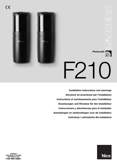
<strong>Photocells</strong><br />
<strong>F210</strong><br />
Installation instructions and warnings<br />
Istruzioni ed avvertenze per l’installatore<br />
Instructions et avertissements pour l'installateur<br />
Anweisungen und Hinweise für den Installateur<br />
Instrucciones y advertencias para el instalador<br />
Aanwijzingen en aanbevelingen voor de installateur<br />
Instrukcje i ostrzeżenia dla instalatora
1) Warnings<br />
This manual contains important information regarding safety during<br />
installation, therefore before starting installation, it is important that you<br />
read all the information contained herein. Store this manual in a safe<br />
place for future use.<br />
Due to the dangers which may arise during both the installation and use of<br />
the <strong>F210</strong>, installation must be carried out in full respect of the laws, provisions<br />
and rules currently in force in order to ensure maximum safety.<br />
According to the most recent European legislation, the automation<br />
of a door or gate is governed by the provisions listed in Directive<br />
98/37/CE (Machine Directive) and, more specifically, to provisions:<br />
EN 13241-1 (harmonized standard); EN 12445; EN 12453<br />
and EN 12635, which enable to declare the conformity of the<br />
product to the machine directive.<br />
Further information, risk analysis guidelines and how to draw up the<br />
Technical Documentation is available at: www.niceforyou.com. This manual<br />
has been especially written for use by qualified fitters, none of the<br />
information provided in this manual can be considered as being of interest<br />
to end users!<br />
• The use of <strong>F210</strong> which is not explicitly provided for in these instructions<br />
is not permitted. Improper use may cause damage and personal injury.<br />
• Do not modify any components unless such action is specified in these<br />
instructions. Operations of this kind are likely to lead to malfunctions.<br />
NICE disclaims any liability for damage resulting from modified products<br />
• <strong>F210</strong> must only function through TX-RX direct interpolation. Use<br />
through reflection is prohibited.<br />
• <strong>F210</strong> must be secured to a solid and vibration free surface.<br />
• Use suitable conductors for the electrical connections as specified in<br />
the “installation” chapter.<br />
• Make sure that the electrical power supply and the other use parameters<br />
correspond to the values indicated in “technical characteristics” table.<br />
Particular warnings concerning the suitable use of this product in relation<br />
to the 89/336/EEC “Electromagnetic Compatibility” Directive and subsequent<br />
modifications 92/31/EEC and 93/68/EEC: This product has been<br />
subjected to tests regarding the electromagnetic compatibility in the<br />
most critical of use conditions, in the configurations foreseen in this<br />
instructions manual and in combination with articles present in the <strong>Nice</strong><br />
S.p.a. product catalogue. The electromagnetic compatibility may not be<br />
guaranteed if used in configurations or with other products that have not<br />
been foreseen; the use of the product is prohibited in these situations<br />
until the correspondence to the requirements foreseen by the directive<br />
have been verified by those performing the installation.<br />
2) Product description and applications<br />
The <strong>F210</strong> directional photocells are presence detectors (type D according<br />
to the EN12453 standard) that can be used in gate, door and similar<br />
automation systems, which allow the detection of obstacles present on<br />
the optical axis between the transmitter (TX) and the receiver (RX).<br />
Because the <strong>F210</strong> photocells have a horizontal scope of 210° and a vertical<br />
scope of 30°, they can also be applied on uneven surfaces where<br />
the correct alignment between TX and RX is not possible (see fig, 1).<br />
An additional vandal-proof metal container is also available on request,<br />
code FA1.<br />
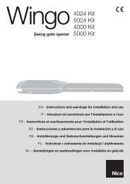
3) Installation<br />
! The system must be disconnected from the mains power supply<br />
during installation. If buffer batteries are present, these must<br />
also be disconnected.<br />
Check the following points before proceeding with the installation:<br />
1. If the photocells have a 12V power supply, a solder jumper must be<br />
made between the two “12V” points on the weld side of the TX and<br />
of the RX (see details A and B of fig. 2). To access the jumpers, separate<br />
the electronic board from the base using a screwdriver to lever<br />
the three clips as indicated in fig. 9.<br />
2. If the distance between TX and RX is greater than 10 m, cut the<br />
jumper between the points “>10m” of the RX, as indicated in detail C<br />
of fig. 2.<br />
3. The TX transmitter of the photocell emits a beam with an angle of<br />
approximately 8°. If there are two devices close to one another the<br />
beam could interfere with the other receiver (fig, 3 and fig. 4) thereby<br />
not guaranteeing an adequate level of safety. In order to rectify this<br />
problem, a synchronism system can be implemented that allows two<br />
pairs of photocells to function alternately, if an alternating current power<br />
supply is available. In order to use this system the “SYNC” synchronism<br />
jumper on the two TX must be cut (see detail D of fig. 2) and<br />
the first pair of photocells (TX and RX) must be supplied with the phases<br />
inverted in relation to the second pair (see fig. 5).<br />
4. Depending on the type of installation, the cable can be introduced either<br />
from the base or from the lower edge. In this case a “PG9” type cable<br />
clip must be added (as shown in fig. 6 and 7).<br />
5. Fix the photocell as shown in fig. 8.<br />
To separate the electronic board from the base, use a screwdriver to<br />
lever the three clips as indicated in fig. 9.<br />
6. Following that indicated in the control unit manual and that indicated<br />
in fig. 10, make the electrical connections based on the requested<br />
functions.<br />
7. Direct the lenses as in fig. 11 in order to obtain the correct alignment<br />
between the TX and RX.<br />
4) Testing<br />
Each individual component of the automation system requires a specific<br />
testing phase. Perform the following sequence of operations for the testing<br />
of the <strong>F210</strong>.<br />
1. Make sure that the provisions contained in this manual, in particular<br />
chapter 1 “WARNINGS”, have been carefully observed.<br />
2. Connect the power supply to the TX and RX of the <strong>F210</strong>, make sure<br />
there are no obstacles between the TX and RX and check the photocell<br />
status in table 1 based on the type of LED “L” signals, (see fig.11).<br />
Table 1<br />
LED “L” Meaning Output status Action<br />
Off OK signal = No obstacle Active All OK<br />
Slow flash Weak signal = No obstacle Active Improve centring<br />
Rapid flash Poor signal = No obstacle Active Check centring, cleanliness and surroundings<br />
Always on No signal = Obstacle present Alarm Remove obstacl<br />
2
3. If necessary, improve the alignment by changing the direction of the<br />
TX and RX lenses as in fig. 11<br />
Follow the signals of indicator “L”: the slower the flash the better the<br />
alignment.<br />
The best alignment is obtained when the indicator is off or when the<br />
flashes are very slow, which is in any case acceptable, whereas the<br />
alignment is at risk when the indicator flashes rapidly.<br />
4. To check the photocells and make sure that there is no interference<br />
with other devices, pass a 5 cm diameter cylinder across the optical<br />
axis, first near TX, then near RX and finally between the two (see fig.<br />
12) and make sure that in all these cases the device is triggered,<br />
switching from the active status to the alarm status and vice-versa;<br />
finally, that it causes the intended action in the control unit on the<br />
automation system, for example that it causes the reversal of the<br />
movement during the closing manoeuvre.<br />
5. The control of the correct obstacle detection is performed with the<br />
700x300x200mm test parallelepiped with 3 black sides and 3 polished<br />
white or mirrored sides, according to the EN 12445 standard<br />
(see fig. 13).<br />
GB<br />
5) Maintenance<br />
The photocells do not require any particular maintenance, however a<br />
control should be performed at least once every six months to check the<br />
integrity of the photocells (presence of dampness, rust, etc), cleaning of<br />
the external casing and testing as described in chapter 4 “Testing”.<br />
The photocells have been designed to function under normal conditions<br />
for at least 10 years, therefore maintenance should be performed more<br />
frequently once this period has expired.<br />
6) Disposal<br />
This product is made of various types of material, some of which can be<br />
recycled. Enquire about the recycling or disposal systems available in<br />
compliance with regulations locally in force.<br />
! Some electronic components may contain polluting substances;<br />
do not pollute the environment and do not discard<br />
together with household refuse. Use the disposal methods in<br />
compliance with local regulations.<br />
7) Accessories<br />
Two accessories are available on request:<br />
1. Metal vandal-proof casing (code FA1), fitted as in fig. 14);<br />
2. Fixing brackets (code FA2) for “MOCF” posts, fitted as in fig. 15;<br />
8) Technical characteristics<br />
In order to improve its products, NICE S.p.a. reserves the right to modify them at any time without prior notice. In any case, the manufacturer guarantees<br />
their functionality and fitness for the intended purposes<br />
Note: all the technical characteristics refer to a temperature of 20°C.<br />
<strong>F210</strong> directional photocell<br />
Product type<br />
Presence detector for automated gates and doors (type D according to EN standard 12453) consisting of a<br />
“TX” transmitter and an “RX” receiver<br />
Adopted technology<br />
TX-RX direct optical interpolation with modulated infrared beam<br />
Power supply/output Without jumper: 24 Vac/Vdc (limits 18÷35 Vdc,15÷28Vac)<br />
With “12V” jumper: 12 Vac/Vdc (limits 10÷18 Vdc , 9÷15 Vac)<br />
Absorbed current<br />
25mA RX, 30mA TX = 55mA per pair<br />
Detection capacity<br />
Opaque objects located on the optical axis between TX and RX, larger than 50 mm and moving slower than 1.6m/s<br />
TX transmission angle<br />
+/- 4° (value taken at 50% of the capacity)<br />
RX reception angle<br />
+/- 3° (value taken at 50% of the capacity)<br />
<strong>F210</strong> photocell directional capacity Approx. 210° on the horizontal axis and 30° on the vertical axis<br />
Useful range<br />
10 m (30 m with “>10m” jumper cut) for maximum TX-RX misalignment ± 2° (the range may be further<br />
reduced in the presence of particularly intense atmospheric conditions: fog, rain, snow, dust, etc.).<br />
Maximum range<br />
20 m (60 m with “>10m” jumper cut) for maximum TX-RX misalignment ± 2° (range guaranteed under<br />
optimum conditions)<br />
Use in acid, saline or potentially No<br />
explosive atmosphere<br />
Mounting<br />
Vertically wall mounted or on “MOCF” posts with “FA2” bracket.<br />
Protection class casing<br />
IP44<br />
Operating temperature<br />
-20 ÷55°C<br />
Dimensions / weight<br />
46 x 128 h 45mm / 230 g<br />
<strong>Nice</strong> S.p.a. reserves the right to modify its products at any time.<br />
3
1<br />
C<br />
B<br />
3<br />
D<br />
A<br />
2<br />
4<br />
5<br />
16
6 7<br />
8 9<br />
L<br />
10<br />
11<br />
12<br />
13<br />
14 15<br />
17
Dichiarazione CE di conformità / EC declaration of conformity<br />
(Secondo la Direttiva 89/336/CEE) (According to Directive 89/336/EEC)<br />
Numero / Number: 216/<strong>F210</strong> Data / Date: 02-02-2005 Revisione / Revision: 0<br />
Il sottoscritto Lauro Buoro, Amministratore Delegato, dichiara che il prodotto<br />
The undersigned Lauro Buoro, General Manager of the following producer, declares that the product<br />
Nome produttore / Producer name:<br />
Indirizzo / Address:<br />
Tipo / Type:<br />
Modello / Model:<br />
Accessori / Accessories:<br />
NICE S.p.a.<br />
Via Pezza Alta 13, 31046 Z.I. Rustignè - ODERZO - ITALY<br />
Fotocellula orientabile / <strong>F210</strong> directional photocell<br />
<strong>F210</strong><br />
Box metallico antivandalico FA1 / Vandal-proof metal container FA1<br />
Risulta conforme a quanto previsto dalle seguenti direttive comunitarie, così come modificate dalla Direttiva 93/68/CEE del<br />
consiglio del 22 Luglio 1993: / Satisfies the essential requirements of Electromagnetic Compatibility Directive 89/336/EEC.<br />
• 89/336/CEE; DIRETTIVA 89/336/CEE DEL CONSIGLIO del 3 maggio 1989, per il riavvicinamento delle legislazioni degli Stati membri relative alla<br />
compatibilità elettromagnetica. / 89/336/EEC DIRECTIVE 89/336/EEC OF THE COUNCIL of May 3, 1989, for the harmonisation of the legislations<br />
of member States regarding electromagnetic compatibility.<br />
Secondo le seguenti norme: EN 61000-6-2; EN 61000-6-3 / In compliance with the following harmonised standards: EN 61000-6-2; EN 61000-6-3<br />
Oderzo, 2 Febbraio 2005<br />
Amministratore delegato<br />
(General Manager)<br />
Lauro Buoro
<strong>Nice</strong> SpA<br />
Oderzo TV Italia<br />
Tel. +39.0422.85.38.38<br />
Fax +39.0422.85.35.85<br />
info@niceforyou.com<br />
<strong>Nice</strong> Padova<br />
Sarmeola di Rubano PD Italia<br />
Tel. +39.049.89.78.93.2<br />
Fax +39.049.89.73.85.2<br />
infopd@niceforyou.com<br />
<strong>Nice</strong> Roma<br />
Roma Italia<br />
Tel. +39.06.72.67.17.61<br />
Fax +39.06.72.67.55.20<br />
inforoma@niceforyou.com<br />
<strong>Nice</strong> Gate is the doors and gate automation division of <strong>Nice</strong><br />
<strong>Nice</strong> France<br />
Buchelay<br />
Tel. +33.(0)1.30.33.95.95<br />
Fax +33.(0)1.30.33.95.96<br />
<strong>Nice</strong> Rhône-Alpes<br />
Decines Charpieu France<br />
Tel. +33.(0)4.78.26.56.53<br />
Fax +33.(0)4.78.26.57.53<br />
<strong>Nice</strong> France Sud<br />
Aubagne France<br />
Tel. +33.(0)4.42.62.42.52<br />
Fax +33.(0)4.42.62.42.50<br />
<strong>Nice</strong> Belgium<br />
Leuven (Heverlee)<br />
Tel. +32.(0)16.38.69.00<br />
Fax +32.(0)16.38.69.01<br />
info@be.niceforyou.com<br />
<strong>Nice</strong> España Madrid<br />
Tel. +34.9.16.16.33.00<br />
Fax +34.9.16.16.30.10<br />
info@es.niceforyou.com<br />
<strong>Nice</strong> España Barcelona<br />
Tel. +34.9.35.88.34.32<br />
Fax +34.9.35.88.42.49<br />
info@es.niceforyou.com<br />
<strong>Nice</strong> Screen is the rolling shutters and awnings automation division of <strong>Nice</strong><br />
<strong>Nice</strong> Polska<br />
Pruszków<br />
Tel. +48.22.728.33.22<br />
Fax +48.22.728.25.10<br />
info@pl.niceforyou.com<br />
<strong>Nice</strong> UK<br />
Chesterfield<br />
Tel. +44.87.07.55.30.10<br />
Fax +44.87.07.55.30.11<br />
info@uk.niceforyou.com<br />
<strong>Nice</strong> China<br />
Shanghai<br />
Tel. +86.21.575.701.46/45<br />
Fax +86.21.575.701.44<br />
info@cn.niceforyou.com<br />
www.niceforyou.com<br />
IST190.4854 REV.00 del 15-04-2005
<strong>Photocells</strong><br />
<strong>F210</strong>B<br />
Instructions and warnings for the fitter<br />
Istruzioni ed avvertenze per l’installatore<br />
Instructions et recommandations pour l’installateur<br />
Anweisungen und Hinweise für den Installateur<br />
Instrucciones y advertencias para el instalador<br />
Instrukcje i ostrzeżenia dla instalatora<br />
Aanwijzigen en aanbevelingen voor het installeren
1) Warnings<br />
This manual contains important information regarding safety during installation,<br />
therefore before starting installation, it is important that you read all the<br />
information contained herein. Store this manual in a safe place for future use.<br />
Due to the dangers which may arise during both the installation and use of the<br />
<strong>F210</strong>B, installation must be carried out in full respect of the laws, provisions<br />
and rules currently in force in order to ensure maximum safety.<br />
According to the most recent European legislation, the automation of a<br />
door or gate is governed by the provisions listed in Directive 98/37/CE<br />
(Machine Directive) and, more specifically, by provisions: EN 13241-1<br />
(harmonized standard); EN 12445; EN 12453 and EN 12635, which enable<br />
to declare the conformity of the product to the machine directive.<br />
Further information, risk analysis guidelines and how to draw up the Technical<br />
Documentation are available at: www.niceforyou.com. This manual has been<br />
especially written for use by qualified fitters, none of the information provided<br />
in this manual can be considered as being of interest to end users!<br />
• The use of <strong>F210</strong>B which is not explicitly provided for in these instructions is<br />
not permitted. Improper use may cause damage and personal injury.<br />
• Do not modify any components unless such action is specified in these<br />
instructions. Operations of this type are likely to lead to malfunctions. NICE<br />
disclaims any liability for damage resulting from modified products<br />
• <strong>F210</strong>B must only function through TX-RX direct interpolation. Use through<br />
reflection is prohibited.<br />
• The photocell must be secured to a solid and vibration free surface.<br />
• Use suitable conductors for the electrical connections as specified in the<br />
control unit manuals.<br />
• The <strong>F210</strong>B photocells can only be connected to control units with “Blue-<br />
Bus” technology.<br />
Particular warnings concerning the suitable use of this product in relation to<br />
the 89/336/EEC “Electromagnetic Compatibility” Directive and subsequent<br />
modifications 92/31/EEC and 93/68/EEC:<br />
This product has been subjected to tests regarding the electromagnetic compatibility<br />
in the most critical of use conditions, in the configurations foreseen<br />
in this instructions manual and in combination with articles present in the <strong>Nice</strong><br />
S.p.a. product catalogue. The electromagnetic compatibility may not be guaranteed<br />
if used in configurations or with other products that have not been<br />
foreseen; the use of the product is prohibited in these situations until the correspondence<br />
to the requirements foreseen by the directive have been verified<br />
by those performing the installation.<br />
2) Product description and applications<br />
The <strong>F210</strong>B directional photocells are presence detectors (type D according to<br />
the EN12453 standard) that can be used in gate automation systems, which<br />
allow the detection of obstacles present on the optical axis between the transmitter<br />
(TX) and the receiver (RX).<br />
The photocells have a “BlueBus” type communication that allows all devices<br />
to be easily connected to the control unit with just two wires. The photocells<br />
are simply connected in parallel and the addressing jumpers are selected<br />
depending on the required function (see table 1).<br />
Because the <strong>F210</strong>B can be horizontally directed through 210° and vertically<br />
directed through 30°, it can also be applied on surfaces where the correct alignment<br />
between the TX and RX would not normally be possible (see figure 1).<br />
The <strong>F210</strong>B photocells can be used along with the new “FT210B” series of<br />
devices (see figures 2 and 3). The FT210B device uses the “BlueBUS” technology<br />
and resolves problems related to the electrical connection of sensitive<br />
edges on the moving leaf (for further details consult the FT210B use manual).<br />
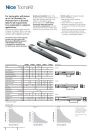
3) Installation<br />
! The system must be disconnected from the mains power supply<br />
during installation. If buffer batteries are present, these must also be<br />
disconnected.<br />
• Check carefully that the use parameters conform to the data indicated in the<br />
“technical characteristics” chapter. If in doubt, do not use the product and ask<br />
clarification from the <strong>Nice</strong> technical assistance department.<br />
Proceed with the installation checking the following points:<br />
1. Depending on the type of automation, position the photocells based on the<br />
detection functions. Check the foreseen positions in figures 2, 3, 4 and 5<br />
and set the jumpers following table 1.<br />
To rectify interference between the various “BlueBus” devices, position the<br />
photocell transmitters and receivers as shown in figures 2 and 3.<br />
If the photocell needs to be used as an opening device (see figures 2, 3, 4<br />
and 5, and the FA1 and FA2 addresses in table 1), cut the jumper between<br />
points “A” both on the TX and on the RX as shown in fig. 6<br />
2. If necessary, the <strong>F210</strong>B can be installed on a special MOCF post, with the<br />
appropriate FA2 accessory (see figure 7), or wall mounted. If the <strong>F210</strong>B is<br />
wall mounted, the cable can be introduced from the base (see figure 8) or<br />
from below. In this case a “PG9” cable clip is required (see figure 9).<br />
3. To aid the fixing operation, the electronic board can be detached from the<br />
base using a screw driver to lever the three clips as shown in figure 10.<br />
4. Fix the receiver as shown in figure 11.<br />
5. If the distance between TX and RX is greater than 10 m, cut the jumper<br />
between points “> 10 m” of the RX as shown in figure 6.<br />
7. Connect the electric cable to both the TX and RX terminals. From an electrical<br />
point of view, the TX and RX are connected together in parallel (as<br />
shown in figure 12) and to the “BlueBus” interface or control unit terminal.<br />
The polarity does not have to be respected<br />
8. Direct the lenses as shown in figure 13 so that the TX and RX are perfectly<br />
aligned.<br />
4) Addressing and recognition of the devices<br />
The particular “BlueBus” communication system allows the control unit to<br />
recognise the photocells, by means of addressing with the appropriate<br />
jumpers, and to assign the correct detection operation. The addressing<br />
operation is performed both on the TX as well as on the RX (positioning the<br />
jumpers in the same manner) making sure that there are no other photocell<br />
pairs with the same address.<br />
1. Address the photocells based on the required operation, positioning the<br />
jumpers as shown in table 1.<br />
Place the jumpers that are not used in the spare location for future use,<br />
as shown in figure 14.<br />
Note: For the detailed description of the various operations performed and<br />
each type of addressing, consult the “BlueBus” technology interface and<br />
control units use manual.<br />
Note: to rectify interference between the various “BlueBus” devices, position<br />
the photocell transmitters and receivers as shown in figures 2 and 3.<br />
2. Perform the programming of the devices on the control unit as illustrated<br />
in paragraph “Recognition of connected devices” in the various “Blue-<br />
Bus” interface or control unit use manuals.<br />
Table 1<br />
Photocell<br />
FOTO<br />
FOTO II<br />
FOTO 1<br />
FOTO 1 II<br />
FA1 (cut jumper A<br />
on TX and RX as<br />
shown in figure 6)<br />
Jumpers Photocell Jumpers<br />
FOTO 2<br />
FOTO 2 II<br />
FOTO 3<br />
FA2 (cut jumper A<br />
on TX and RX as<br />
shown in figure 6)<br />
Note: If the photocell is used in replacement of an already existing photocell, the jumpers are positioned in exactly the same way as that of the replaced photocell<br />
and the recognition phase is not necessary.<br />
3. If necessary, improve the alignment of the TX and RX lenses as shown in figure 13. Perform the L1 Led signalling (Ir Level), the slower the flash the better the<br />
alignment. The best alignment is when the L1 Led flashes slowly with a maximum of 3 flashes per second.<br />
2
5) Testing and operational control<br />
After the recognition phase make sure that the Led on the photocell flashes (both on the TX and on the RX). Check the status of the photocell on table 2 based<br />
on the type of flash of the Led “L”.<br />
GB<br />
Table 2<br />
L<br />
LED “L”<br />
Off<br />
3 fast flashes and<br />
1second pause<br />
Very slow flashing<br />
Slow flashing<br />
Fast flashing<br />
Very fast flashing<br />
Always on<br />
Status<br />
The photocell is either<br />
disconnected or malfunctioning<br />
Device not recognised by the<br />
control unit<br />
The TX transmits properly<br />
The RX receives a perfect signal<br />
The RX receives a fair signal<br />
The RX receives a weak signal<br />
The RX receives a very poor<br />
signal<br />
The RX does not receive any<br />
signal<br />
Action<br />
Check that a voltage of approximately 8-12 Vdc is present on the<br />
photocell terminals. If the voltage is correct the photocell is probably<br />
malfunctioning<br />
Repeat the recognition phase from the control unit, making sure that all<br />
photocell pairs have different addresses<br />
Normal operation<br />
Normal operation<br />
Normal operation but the the TX-RX alignment should be checked as<br />
well as the cleanness of the glasses<br />
It is at the limit of normal operation, the TX-RX alignment should be<br />
checked as well as the cleanness of the glasses<br />
Make sure that the LED on the TX flashes very slowly. Check to see if<br />
there is an obstacle between TX and RX. Check the TX-RX alignment<br />
Warning: testing of the entire automation must be performed again in accordance<br />
with that foreseen in the related installation manuals after photocells<br />
have been added or replaced.<br />
To check the photocells and to make sure that there is no interference with<br />
other devices, pass a 5 cm diameter, 30 cm long cylinder on the optical axis,<br />
first near TX, then near RX and finally at the mid-point between them (see Figure<br />
15) and make sure that in all these cases the device is triggered, switching<br />
from the active to the alarm status and vice-versa. Finally, make sure that<br />
the the intended action occurs in the control unit, for example that it causes<br />
the reversal of the movement during the closing manoeuvre.<br />
The control of the <strong>F210</strong>B optical presence sensor (type D) according to the<br />
EN 12445 standard, is performed with the 700x300x200mm test parallelepiped<br />
with 3 black sides and 3 polished white or mirrored sides as indicated<br />
in figure 16 and according to chapter 7 of the EN 12445:2000 standard<br />
(or enclosure A of prEN12445:2005).<br />
6) Maintenance<br />
The photocell does not require any particular maintenance, however a control<br />
should be performed at least once every six months to check its integrity<br />
(presence of dampness, rust, etc), as well as cleaning of the external casing<br />
and lenses and testing as described in the previous paragraph. The <strong>F210</strong>B<br />
photocell has been designed to function under normal conditions for at least<br />
10 years, therefore maintenance should be performed more frequently once<br />
this period has expired.<br />
6.1) Disposal<br />
As for the installation, the disposal of the product, at the end of its effective<br />
life, must be performed by qualified personnel. This product is made of various<br />
types of material, some of which can be recycled while others must be<br />
disposed of. Enquire about the recycling or disposal systems available for this<br />
product category in compliance with regulations locally in force<br />
Warning: some parts of the product may contain polluting or hazardous substances<br />
that, if incorrectly disposed of, could have a damaging effect on the<br />
environment or on the health of individuals.<br />
As indicated by the symbol in figure 17, this product<br />
must not be disposed of along with household<br />
waste. Perform “separated collection” for disposal in<br />
compliance with regulations locally in force, or return<br />
the product to the manufacturer when purchasing a<br />
replacement.<br />
Heavy fines may be imposed by local laws for the illegal disposal of this product.<br />
17<br />
7) Technical characteristics<br />
In order to improve its products, NICE S.p.a. reserves the right to modify the technical characteristics at any time without prior notice. In any case, the<br />
manufacturer guarantees their functionality and fitness for the intended purposes.<br />
Note: all technical characteristics refer to a temperature of 20°C.<br />
<strong>F210</strong>B directional photocell<br />
Product type Presence detector for automatic gate and door automation systems (type D according to EN standard 12453),<br />
consisting in a “TX” transmitter and “RX” receiver.<br />
Adopted technology<br />
TX-RX direct optical interpolation with modulated infrared beam<br />
Power supply/output<br />
The device can be connected to “BlueBus” networks only from which it obtains its power supply and sends<br />
output signals.<br />
Absorbed power<br />
1 BlueBus unit<br />
Detection capacity<br />
Opaque objects located on the optical axis between TX and RX, larger than 50 mm and moving slower than 1.6m/s<br />
TX transmission angle<br />
+/- 4° (value taken at 50% of the capacity)<br />
RX reception angle<br />
+/- 3° (value taken at 50% of the capacity)<br />
Adjustability of the <strong>F210</strong>B photocell<br />
Useful range<br />
Approximately 210° on the horizontal axis and 30° on the vertical axis<br />
10m or 30m with the “>10m” jumper cut for maximum TX-RX misalignment ± 2° (the range may be further<br />
reduced in the presence of particularly intense atmospheric conditions: fog, rain, snow, dust, etc.)<br />
Maximum range 20m or 60m with the “>10m” jumper cut for maximum TX-RX misalignment ± 2°<br />
(capacity guaranteed under optimal conditions)<br />
Maximum length of cable<br />
Up to 50m<br />
Addressing capability<br />
Up to 7 detectors with safety function and 2 with open command function.<br />
The automatic synchronism prevents interference between the various detectors .<br />
Use in acid, saline or potentially<br />
No<br />
explosive atmosphere<br />
Assembly<br />
Vertically wall mounted or on “MOCF” posts with “FA2” bracket.<br />
Casing protection class<br />
IP44<br />
Operating temperature<br />
20÷55°C<br />
Dimensions / weight<br />
46 x 128 h 45mm / 230 g<br />
3
1<br />
SINGLE LEAF SLIDING GATE<br />
CANCELLO SCORREVOLE AD ANTA SINGOLA<br />
PORTAIL COULISSANT À UN SEUL VANTAIL<br />
EINTEILIGES SCHIEBETOR<br />
PUERTA DE CORREDERA DE UNA HOJA<br />
BRAMA PRZESUWNA Z JEDNYM SKRZYDŁEM<br />
SCHUIFPOORT MET ENKELE VLEUGEL<br />
TX<br />
RX<br />
RX<br />
TX<br />
RX<br />
TX<br />
RX<br />
TX<br />
RX<br />
RX<br />
TX<br />
RX<br />
TX<br />
2<br />
TX<br />
SYNCHRONISED LEAFS SLIDING GATE<br />
CANCELLO SCORREVOLE AD ANTE CONTRAPPOSTE<br />
PORTAIL COULISSANT À VANTAUX OPPOSÉS<br />
SCHIEBETOR MIT ENTGEGENGESETZT ANGEBRACHTEN TORFLÜGELN<br />
PUERTA DE CORREDERA DE HOJAS CONTRAPUESTAS<br />
BRAMA PRZESUWNA Z DWOMA PRZECIWLEŻĄCYMI SKRZYDŁAMI<br />
SCHUIFPOORT MET TEGENGESTELDE VLEUGELS<br />
RX<br />
TX<br />
RX<br />
RX<br />
TX<br />
RX<br />
TX<br />
TX<br />
RX<br />
TX<br />
RX<br />
TX<br />
3<br />
RX<br />
TX<br />
SWING GATE<br />
CANCELLO A BATTENTE<br />
PORTAIL BATTANT<br />
DREHTOR<br />
PUERTA DE BATIENTE<br />
BRAMA SKRZYDŁOWA<br />
KANTELDEUR VOOR GARAGE<br />
16<br />
4
SECTIONAL DOOR<br />
GARAGE SEZIONALE<br />
PORTE SECTIONNELLE<br />
SEKTIONALTOR<br />
GARAJE SECCIONAL<br />
BRAMA GARAŻOWA SEKCYJNA<br />
SECTIONAALGARAGEDEUR<br />
UP & OVER GARAGE DOORS<br />
GARAGE BASCULANTE<br />
PORTE DE GARAGE BASCULANTE<br />
GARAGENKIPPTOR<br />
GARAJE BASCULANTE<br />
GARAZ BRAMA UCHYLNA<br />
KANTELDEUR VOOR GARAGE<br />
5<br />
6<br />
7 8 9<br />
10 11<br />
12<br />
13<br />
14<br />
15<br />
16<br />
17
Dichiarazione CE di conformità / EC declaration of conformity<br />
(Secondo la Direttiva 89/336/CEE) (According to Directive 89/336/EEC)<br />
Nota: il contenuto di questa dichiarazione di conformità corrisponde all'ultima revisione aggiornata alla data di edizione del presente<br />
documento; eventualmente riadattato per motivi editoriali. La versione integrale ed aggiornata della presente dichiarazione<br />
è depositata presso la sede di <strong>Nice</strong> S.p.a.<br />
Note: the content of this declaration of conformity correspond to the last revision updated on the edition date of the present document; readapted<br />
for editorial reasons. The integral and updated version of the present document is held at the Head Offices of <strong>Nice</strong> S.p.a.<br />
Numero / Number: 215/<strong>F210</strong>B Data / Date: 11/10/2005 Revisione / Revision: 0<br />
Il sottoscritto Lauro Buoro, Amministratore Delegato, dichiara che il prodotto<br />
The undersigned Lauro Buoro, General Manager of the following producer, declares that the product<br />
Nome produttore / Producer name:<br />
Indirizzo / Address:<br />
Modello / Model:<br />
Accessori / Accessories:<br />
NICE S.p.a.<br />
Via Pezza Alta 13, 31046 Z.I. Rustignè - ODERZO - ITALY<br />
<strong>F210</strong>B<br />
Box metallico antivandalico FA1 / Vandal-proof metal container FA1<br />
Risulta conforme a quanto previsto dalle seguenti direttive comunitarie, così come modificate dalla Direttiva 93/68/CEE del<br />
consiglio del 22 Luglio 1993:<br />
Complies with the following community directives, as modified from Directive 93/68/EEC of the Council of the 22 July 1993.<br />
• 89/336/CEE; DIRETTIVA 89/336/CEE DEL CONSIGLIO del 3 maggio 1989, per il riavvicinamento delle legislazioni degli Stati membri relative alla<br />
compatibilità elettromagnetica. / 89/336/CEE; Council Directive of 3 May 1989 on the approximation of the laws of the Member States relating to Electromagnetic<br />
Compatibility).<br />
Secondo le seguenti norme: EN 61000-6-2; EN 61000-6-3 / Complies with the following standards: EN 61000-6-2; EN 61000-6-3<br />
Oderzo, 11 Ottobre 2005<br />
Amministratore delegato<br />
(General Manager)<br />
Lauro Buoro
<strong>Nice</strong> SpA<br />
Oderzo TV Italia<br />
Tel. +39.0422.85.38.38<br />
Fax +39.0422.85.35.85<br />
info@niceforyou.com<br />
<strong>Nice</strong> France<br />
Buchelay<br />
Tel. +33.(0)1.30.33.95.95<br />
Fax +33.(0)1.30.33.95.96<br />
info@fr.niceforyou.com<br />
<strong>Nice</strong> Belgium<br />
Leuven (Heverlee)<br />
Tel. +32.(0)16.38.69.00<br />
Fax +32.(0)16.38.69.01<br />
info@be.niceforyou.com<br />
<strong>Nice</strong> Polska<br />
Pruszków<br />
Tel. +48.22.728.33.22<br />
Fax +48.22.728.25.10<br />
info@pl.niceforyou.com<br />
<strong>Nice</strong> Padova<br />
Sarmeola di Rubano PD Italia<br />
Tel. +39.049.89.78.93.2<br />
Fax +39.049.89.73.85.2<br />
infopd@niceforyou.com<br />
<strong>Nice</strong> Roma<br />
Roma Italia<br />
Tel. +39.06.72.67.17.61<br />
Fax +39.06.72.67.55.20<br />
inforoma@niceforyou.com<br />
<strong>Nice</strong> Gate is the doors and gate automation division of <strong>Nice</strong><br />
<strong>Nice</strong> Rhône-Alpes<br />
Decines Charpieu France<br />
Tel. +33.(0)4.78.26.56.53<br />
Fax +33.(0)4.78.26.57.53<br />
infolyon@fr.niceforyou.com<br />
<strong>Nice</strong> France Sud<br />
Aubagne France<br />
Tel. +33.(0)4.42.62.42.52<br />
Fax +33.(0)4.42.62.42.50<br />
infomarseille@fr.niceforyou.com<br />
<strong>Nice</strong> Romania<br />
Cluj Napoca<br />
info@ro.niceforyou.com<br />
<strong>Nice</strong> Deutschland<br />
Frankfurt<br />
info@de.niceforyou.com<br />
<strong>Nice</strong> España Madrid<br />
Tel. +34.9.16.16.33.00<br />
Fax +34.9.16.16.30.10<br />
info@es.niceforyou.com<br />
<strong>Nice</strong> España Barcelona<br />
Tel. +34.9.35.88.34.32<br />
Fax +34.9.35.88.42.49<br />
info@es.niceforyou.com<br />
<strong>Nice</strong> Screen is the rolling shutters and awnings automation division of <strong>Nice</strong><br />
<strong>Nice</strong> UK<br />
Chesterfield<br />
Tel. +44.87.07.55.30.10<br />
Fax +44.87.07.55.30.11<br />
info@uk.niceforyou.com<br />
<strong>Nice</strong> China<br />
Shanghai<br />
Tel. +86.21.575.701.46<br />
+86.21.575.701.45<br />
Fax +86.21.575.701.44<br />
info@cn.niceforyou.com<br />
www.niceforyou.com<br />
IST182.4854 Rev.00 del 23-11-2005