XLN3640 - 1.44 kW Programmable DC Power Supply - Sefram
XLN3640 - 1.44 kW Programmable DC Power Supply - Sefram
XLN3640 - 1.44 kW Programmable DC Power Supply - Sefram

Create successful ePaper yourself
Turn your PDF publications into a flip-book with our unique Google optimized e-Paper software.
Model: <strong>XLN3640</strong>, XLN6024, XLN8018, XLN10014<br />
High <strong>Power</strong> <strong>Programmable</strong><br />
<strong>DC</strong> <strong>Power</strong> <strong>Supply</strong><br />
USER MANUAL
Safety Summary<br />
The following safety precautions apply to both operating and maintenance personnel<br />
and must be observed during all phases of operation, service, and repair of this<br />
instrument. Before applying power, follow the installation instructions and become<br />
familiar with the operating instructions for this instrument.<br />
Failure to comply with these precautions or with specific warnings elsewhere in this<br />
manual violates safety standards of design, manufacture, and intended use of the<br />
instrument. B&K Precision assumes no liability for a customer’s failure to comply<br />
with these requirements. This is a Safety Class I instrument.<br />
GROUND THE INSTRUMENT<br />
To minimize shock hazard, the instrument chassis and cabinet must be<br />
connected to an electrical ground. This instrument is grounded through the<br />
ground conductor of the supplied, three-conductor ac power cable. The<br />
power cable must be plugged into an approved three-conductor electrical<br />
outlet. Do not alter the ground connection. Without the protective ground<br />
connection, all accessible conductive parts (including control knobs) can<br />
render an electric shock. The power jack and mating plug of the power cable<br />
meet IEC safety standards.<br />
DO NOT OPERATE IN AN EXPLOSIVE ATMOSPHERE<br />
Do not operate the instrument in the presence of flammable gases or fumes.<br />
Operation of any electrical instrument in such an environment constitutes a<br />
definite safety hazard.<br />
KEEP AWAY FROM LIVE CIRCUITS<br />
Instrument covers must not be removed by operating personnel. Component<br />
replacement and internal adjustments must be made by qualified maintenance<br />
personnel. Disconnect the power cord before removing the instrument<br />
covers and replacing components. Under certain conditions, even with the<br />
power cable removed, dangerous voltages may exist. To avoid injuries,<br />
always disconnect power and discharge circuits before touching them.<br />
DO NOT SERVICE OR ADJUST ALONE<br />
Do not attempt any internal service or adjustment unless another person,<br />
capable of rendering first aid and resuscitation, is present.
DO NOT SUBSTITUTE PARTS OR MODIFY THE INSTRUMENT<br />
Do not install substitute parts or perform any unauthorized modifications to<br />
this instrument. Return the instrument to B&K Precision for service and<br />
repair to ensure that safety features are maintained.<br />
WARNINGS AND CAUTIONS<br />
WARNING and CAUTION statements, such as the following examples,<br />
denote a hazard and appear throughout this manual. Follow all instructions<br />
contained in these statements.<br />
A WARNING statement calls attention to an operating procedure, practice, or<br />
condition, which, if not followed correctly, could result in injury or death to<br />
personnel.<br />
A CAUTION statement calls attention to an operating procedure, practice, or<br />
condition, which, if not followed correctly, could result in damage to or<br />
destruction of part or all of the product.<br />
WARNING: Do not alter the ground connection. Without the protective ground<br />
connection, all accessible conductive parts (including control knobs)<br />
can render an electric shock. The power jack and mating plug of the<br />
power cable meet IEC safety standards.<br />
WARNING: To avoid electrical shock hazard, disconnect power cord before<br />
removing covers. Refer servicing to qualified personnel.<br />
CAUTION: Before connecting the line cord to the AC mains, check the rear panel<br />
AC line voltage indicator. Applying a line voltage other than the<br />
indicated voltage can destroy the AC line fuses. For continued fire<br />
protection, replace fuses only with those of the specified voltage and<br />
current ratings.<br />
CAUTION:<br />
This product uses components which can be damaged by<br />
electro-static discharge (ESD). To avoid damage, be sure to follow<br />
proper procedures for handling, storing and transporting parts and<br />
subassemblies which contain ESD-sensitive components.
Store/Move/Maintain<br />
Storage<br />
When this device is not in use, properly package it and store it in an<br />
environment suitable for storage (if present in a good preserving environment,<br />
the packaging process can be waived).<br />
Freight<br />
While moving this product, move it by using the original packaging to pack<br />
this product in advance. If the packaging material is lost, use an equivalent<br />
buffer material to replace it in packaging; and with external marks indicating<br />
“fragile & water-prevention”.<br />
Maintenance<br />
Please return the power supply to factory for any repair, service, or<br />
maintenance.<br />
Disposal<br />
When the device is in an unusable condition and can’t be repaired, please<br />
discard it according to your company’s disposal procedures or local legal<br />
procedures. Don’t discard arbitrarily to avoid polluting the environment.<br />
1
Table of Contents<br />
1. Preface ...................................................................................................... 1<br />
1.1 Products Outline ................................................................................ 1<br />
1.2 Features ............................................................................................. 2<br />
1.3 Specifications .................................................................................... 4<br />
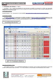
2. Cautions Before Using ............................................................................ 9<br />
2.1 Check and Confirm Accessories before Using .................................. 9<br />
2.2 Operation Instructions ....................................................................... 9<br />
2.3 Ambient Environment ....................................................................... 9<br />
2.4 Storage ............................................................................................. 10<br />
2.5 <strong>Power</strong>-line voltage ........................................................................... 10<br />
2.6 Fuses ................................................................................................ 10<br />
2.7 Warm-up Time ................................................................................. 11<br />
2.8 <strong>Power</strong>-off procedure ........................................................................ 11<br />
2.9 Cautions in Operation ...................................................................... 11<br />
3. Front Panel Operation .......................................................................... 12<br />
3.1 <strong>XLN3640</strong>/XLN6024/XLN8018/XLN10014 Panel ......................... 12<br />
3.1.1 Front Panel ................................................................................. 12<br />
3.1.2 Rear Panel .................................................................................. 29<br />
4. Operation Instructions ......................................................................... 33<br />
4.1 Voltage Setting................................................................................. 33<br />
4.2 Current Setting ................................................................................ 33<br />
4.3 Over-voltage Protection OVP .......................................................... 33<br />
4.4 Over-current Protection OCP .......................................................... 33<br />
4.5 Voltage Output ................................................................................. 34<br />
2
4.6 Control Voltage Output with Rotary knob ....................................... 34<br />
4.7 Timer Function ................................................................................ 34<br />
4.8 Series (cascade) / Parallel Mode Setting ......................................... 35<br />
4.8.1 Parallel Connection Setting ........................................................ 35<br />
4.8.2 Series Mode Setting ................................................................... 37<br />
4.8.3 Error Message of Series/Parallel Connection ............................ 39<br />
4.9 External Tuning Setting ................................................................... 41<br />
4.10 Timer of Current Flow ..................................................................... 42<br />
4.11 <strong>Programmable</strong> Capability (SCPI Command Only) ......................... 43<br />
4.12 Multi-unit Connection mode (RS485) ............................................. 49<br />
5. Protection and Error Messages............................................................ 53<br />
5.1 Over-voltage Protection (OVP) ....................................................... 53<br />
5.2 Over-current Protection (OCP) ........................................................ 53<br />
5.3 Overpower Protection (OPP) ........................................................... 53<br />
5.4 Constant Voltage Protection (CV TO CC) ....................................... 54<br />
5.5 Constant Current Protection (CC TO CV)....................................... 54<br />
5.6 Over-temperature Protection (OTP) ................................................ 54<br />
5.7 Low Voltage Protection (ACD) ....................................................... 55<br />
5.8 Error Input Message ........................................................................ 55<br />
6. Remote Interface communication protocol ........................................ 56<br />
6.1 Prefaces ........................................................................................... 56<br />
6.2 Parameters Definition ...................................................................... 56<br />
6.3 The Error/Event List ........................................................................ 57<br />
6.4 Remote Communication Protocol ................................................... 58<br />
6.5 SCPI Conformity Information ......................................................... 61<br />
6.5.1 Common SCPI commands ......................................................... 61<br />
6.5.2 SCPI Command subsystem ........................................................ 62<br />
3
6.6 State Bit Definition .......................................................................... 73<br />
6.7 LAN Communication (-GL verions) ............................................... 74<br />
Using Web Server........................................................................................... 74<br />
Main Page (Home) .................................................................................. 74<br />
Using Telnet ............................................................................................ 77<br />
Using Sockets .......................................................................................... 77<br />
7. Assemble Accessories ............................................................................ 78<br />
7.1 Assemble Rack Mount Brackets ..................................................... 78<br />
7.2 Assembly of Output Protective Cover<br />
(XLN6024/XLN8018/XLN10014).................................................. 79<br />
7.3 Assembly of Remote Sense Protective Cover<br />
(XLN6024/XLN8018/XLN10014).................................................. 80<br />
8. Accessories ............................................................................................. 81<br />
9. Service Information .............................................................................. 83<br />
10. Limited Two-year Warranty ................................................................ 84<br />
4
1. Preface<br />
1.1 Products Outline<br />
B&K Precision models <strong>XLN3640</strong>/XLN6024/XLN8018/XLN10014 are<br />
programmable <strong>DC</strong> power supplies with single outputs that offer the<br />
maximum power output up to 1440 watts (0 -- 36 V/40 A or 0 -- 60 V/24 A<br />
or 0 -- 80 V/18 A or 0 -- 100 V/14.4 A). With a 16-bit D/A, A/D converter<br />
embedded, the power supplies come with the resolution of 1mV in voltage<br />
setting and 1mA in current setting. By connecting up to 4 power supplies in<br />
parallel or series, a maximum power output up to 5760 watts can be<br />
generated. With four XLN10014 connected in series, the maximum output<br />
voltage can reach 400 V. With four <strong>XLN3640</strong> connected in parallel, the<br />
output current can reach up to 160 A.<br />
The XLN series provides a rotary control knob and numerical and function<br />
keys to make the instrument convenient and easy to use. Additionally, the<br />
power supplies provide a memory space for storage of 10 instrument settings<br />
that can be recalled directly. This feature offers an easy way to restore the<br />
application settings. In addition, users can program to control when to cut off<br />
the output. This feature provides extra safety for burn-in and electroplating<br />
applications. The supplies also provide over voltage protection (OVP), over<br />
current protection (OCP), and over power protection (OPP) features used to<br />
keep the output voltage and current within safety level and preventing<br />
damage to the UUT (Unit Under Test) due to excessive current. The key lock<br />
feature is added to avoid accidental setting changes to the XLN series..<br />
When the input power and the load change, the power supplies maintain a<br />
stable output due to load and line regulation of less than 0.05%; the transient<br />
time less than 1 ms.. In remote mode, the supplies can output a new<br />
voltage/current setting 50 ms after receiving a command, which can increase<br />
the throughput on production lines.<br />
1
1.2 Features<br />
1) Output Voltage & Current<br />
Voltage output range:<br />
(XLN10014)<br />
Current output range:<br />
(XLN10014)<br />
<strong>Power</strong> output range:<br />
0 -- 36V (<strong>XLN3640</strong>) / 0 -- 60V (XLN6024)<br />
0 -- 80V (XLN8018) / 0 -- 100V<br />
0 -- 40A (<strong>XLN3640</strong>) / 0 -- 24A (XLN6024)<br />
0 -- 18A (XLN8018) / 0 -- 14.4A<br />
0 -- 1440W<br />
2) Rotary knob, numerical keys and functions keys<br />
The rotary knob can be used to rapidly change the output voltage setting<br />
and simulate the surge of the voltage output. It offers a good solution for<br />
testing triggering circuits. Numerical keys allow for direct entry of<br />
parameters. Using function keys to switch modes makes the overall<br />
operation more convenient.<br />
3) Precise voltage and current measurement<br />
Besides the precise output, the XLN series also offers the capability to<br />
measure voltage & current accurately (read back), saving users the extra<br />
expense and space for extra measuring instruments.<br />
4) Internal memory and timer function<br />
The XLN series provides a memory space for storage and retrieval of 10<br />
instrument settings. The instruments provide one (1) timer with the<br />
resolution of 1 second. The timers are used to time the outputs. When the<br />
timer counts down to zero the power supply will automatically turn the<br />
output off. This feature is useful when the supply is providing power to the<br />
test object in a burn-in room where operators can precisely set the time<br />
when the equipment is to shut off.<br />
5) OVP (over voltage protection), OCP (over current protection) and OPP<br />
(over power protection) and key lock functions<br />
The over voltage protection (OVP), over current protection (OCP) and over<br />
power protection (OPP) features limit the maximum output current and<br />
voltage to avoid damages to the unit under test (UUT). The key lock<br />
feature disables all keys except the CLR key. It prevents damaging the<br />
2
UUT by accidentally entering the wrong settings.<br />
6) Series & parallel connection mode<br />
The series-parallel connection mode of two or more units (maximum to 4<br />
units) significantly increases the combined output power to a maximum of<br />
5760 W. In parallel connection mode of four <strong>XLN3640</strong> the maximum<br />
output is 36 V/160 A; and in series connection mode of four XLN10014,<br />
the maximum output is 400 V/14.4 A.<br />
7) Multi-unit connection mode<br />
The RS 485 interface can be used to connect multiple power supplies in<br />
series, up to maximum of 31 units. They can be controlled via USB<br />
interface with a computer.<br />
3
1.3 Specifications<br />
<strong>XLN3640</strong>/XLN6024 Specifications<br />
Output Rating <strong>XLN3640</strong> XLN6024<br />
Output Voltage 0--36 V 0--60 V<br />
Output Current 0--40 A 0--24 A<br />
Output <strong>Power</strong> 1440 W 1440 W<br />
Output Protection<br />
OVP Adjustment Range 2--38 V 3--64 V<br />
OVP Accuracy 200 mV 300 mV<br />
Line Regulation<br />
Voltage ≤ 4 mV ≤ 6 mV<br />
Current ≤ 4 mA ≤ 4 mA<br />
Load Regulation<br />
Voltage ≤ 8 mV ≤ 8 mV<br />
Current ≤ 8 mA ≤ 7 mA<br />
Ripple/Noise (20Hz-20MHz)<br />
Normal Mode Voltage<br />
( ≥ 0.5 % of max. power)<br />
≤ 5 mVrms/≤ 60 mVpp<br />
≤ 6 mVrms/≤ 70 mVpp<br />
Normal Mode Current ≤ 90 mA ≤ 70 mA<br />
Programming Resolution<br />
Programming 1 mV/1 mA 1.5 mV/1 mA<br />
Readback 1 mV/1 mA 1.5 mV/1 mA<br />
Programming Accuracy (% output+offset)<br />
Voltage 0.05 %+10 mV 0.05 %+15 mV<br />
Current 0.05 %+10 mA 0.05 %+18 mA<br />
Readback Accuracy ( % output+offset)<br />
Voltage 0.05 %+10 mV 0.05 %+15 mV<br />
Current 0.05 %+10 mA 0.05 %+18 mA<br />
4
General<br />
Average Command Response<br />
Time<br />
XLN8018/XLN10014 Specifications<br />
Output Rate XLN8018 XLN10014<br />
Output Voltage 0~80 V 0~100 V<br />
Output Current 0~18 A 0~14.4 A<br />
Output <strong>Power</strong> 1440 W 1440 W<br />
Output Protection<br />
OVP Adjustment Range 4~85 V 5~105 V<br />
OVP Accuracy 400 mV 500 mV<br />
Line Regulation<br />
Voltage ≤ 8 mV ≤ 10 mV<br />
Current ≤ 4 mA ≤ 4 mA<br />
Load Regulation<br />
Voltage ≤ 10 mV ≤ 12 mV<br />
Current ≤ 6.5 mA ≤ 6 mA<br />
Ripple/Noise (20Hz-20MHz)<br />
Normal Mode Voltage ≤ 7 mVrms/≤ 80<br />
( ≥ 0.5 % of max. power) mVpp<br />
≤ 8 mVrms/≤ 80 mVpp<br />
Normal Mode Current ≤ 50 mA ≤ 40 mA<br />
Programming Resolution<br />
Programming 2 mV/1 mA 2.5 mV/1 mA<br />
Readback 2 mV/1 mA 2.5 mV/1 mA<br />
Programming Accuracy (% output+offset)<br />
Voltage 0.05 %+20 mV 0.05 %+25 mV<br />
Current 0.05 %+7 mA 0.05 %+6 mA<br />
Readback Accuracy ( % output+offset)<br />
Voltage 0.05 %+20 mV 0.05 %+25 mV<br />
Current 0.05 %+7 mA 0.05 %+6 mA<br />
6
General<br />
Average Command<br />
Response Time<br />
<strong>Power</strong> Factor Correction<br />
Features of models <strong>XLN3640</strong>/XLN6024/XLN8018/XLN10014:<br />
• Graphical, easy to read LCD display<br />
• Compact, high efficiency and power density<br />
• 40 A output connector for quick connectivity<br />
• Convenient numerical & function keys<br />
• Store and recall 10 instrument settings<br />
• Timer (1 sec -- 100 hours)<br />
• <strong>Programmable</strong> (SCPI command only)<br />
• List mode supports up to 10 sets of program and maximum 150 steps in<br />
total<br />
• Auxiliary 5 V/1 A output<br />
• Built-in precise voltage and current measurement<br />
• OVP, OCP, OPP and key-lock function<br />
• Series & parallel connection setup (up to 4)<br />
• Multi-unit connection mode via RS485 interface allows connection of up<br />
to 31 power supplies.<br />
• Average measuring time per measurement is 50 ms<br />
• Standard USB interface<br />
• Optional interfaces: GPIB, LAN (order models <strong>XLN3640</strong>-GL,<br />
XLN6024-GL, XLN8018-GL, XLN10014-GL)<br />
8
2. Cautions Before Using<br />
2.1 Check and Confirm Accessories before Using<br />
After receiving this product, please verify the items received in accordance<br />
with the ones listed below:<br />
1. The appearance of the products is without scratch or other damages.<br />
2. Standard parts as shown in parts list of section 8.<br />
2.2 Operation Instructions<br />
In order to avoid damaging the instrument due to improper operation, be<br />
sure to read this user manual. To maintain the specified accuracy, factory<br />
calibration should be performed annually.<br />
2.3 Ambient Environment<br />
1. Do not locate or operate this product in an environment with dust,<br />
vibration, or corrosive gas and do not expose this product directly to<br />
the sunlight. Operate it in an environment with temperature 0--40 o C<br />
& relative humidity 20%--80%. Pause the operation when ambient<br />
temperature is over 40 o C; undo the operation only after the ambient<br />
temperatures drops to the acceptable temperature range. Operating<br />
temperature over the above range would damage the instrument.<br />
2. This product is equipped with one blow-out type cooling fan on the<br />
back board and three in-take cooling fans on inner side of front board.<br />
Provide room for good ventilation near the cooling fans and keep the<br />
boards with a space above 10cm away from wall. To maintain good<br />
accuracy, do not block the ventilation holes in the front and the rear<br />
parts of the unit.<br />
3. Although the product is designed with filters to minimize noise from<br />
AC power source, it is recommended that it be operated in a low<br />
power noise environment with proper earth ground. If the power<br />
noise is unavoidable, please install a power filter.<br />
9
2.4 Storage<br />
The storage temperature range of this product is within -10ºC - 70ºC and<br />
R.H. should be within 80% without moisture condensing. If not operating<br />
this product for a long time interval, pack it with original packaging or<br />
similar one and put it in a dry place without exposure to direct sunlight.<br />
2.5 <strong>Power</strong>-line voltage<br />
Rated AC power source connected to this product is within 100 V-240 V<br />
(refer to the Product Specification for details). Before connecting to external<br />
power source, be sure that the power switch is in OFF state and verify the<br />
suitability of power cable (including the extension line). It should be<br />
compatible with the rated voltage/current and should be firmly connected.<br />
Warning:<br />
The power cable attached with this product is certified<br />
for safety. To change a cable or add an extension cable,<br />
be sure that it can meet the required power ratings of<br />
this product. Any misuse with an additional cable<br />
would void the warranty of this product.<br />
2.6 Fuses<br />
This product is a switching mode power supply. The fuse installed inside is a<br />
multi-barrier protection hardware design. It should not break under normal<br />
operation. In case the fuse does melt, it indicates another malfunction that<br />
causes the fuse to break. In this case, it is suggested to send this product<br />
back to service.<br />
Warning:<br />
Any disassembling of the casing or changing the fuse not<br />
performed by an authorized service technician will void<br />
the warranty of the instrument.<br />
10
2.7 Warm-up Time<br />
The XLN series is fully operable upon switching the power on. However, to<br />
reach the specified equipment accuracy, please allow the supply to warm up<br />
for at least 30 minutes.<br />
2.8 <strong>Power</strong>-off procedure<br />
When the supply is not in use, be sure to turn the power switch on the panel<br />
to the OFF position to turn off the power. After the power switch is turned to<br />
the OFF position, the inner fans will still run for approximately 10-15<br />
seconds to carry on the inside electric capacitor discharge process per safety<br />
code requirement. Once the discharge process is complete, this product will<br />
carry out the automatic shut-down process<br />
2.9 Cautions in Operation<br />
A. While connected in series, each power supplies should be in power-on<br />
state and output should be "ON". In case there is any one supply that is<br />
in power-off state or output is "OFF", the associated output current will<br />
flow over the output bypass diode of the power-off unit and burn it out.<br />
B. While in parallel connection mode, the output voltage of each power<br />
supplies should be set to equal values. If the setting value of each unit is<br />
not the same, the higher output voltage will feed back to the smaller unit<br />
and destroy its inner parts.<br />
C. When the AC input voltage is lower than the full-load voltage which is<br />
100 VAC, the supplies will activate an inner over temperature protector<br />
and cut off the output in response to the condition. To ensure that the<br />
entire test process can be complete smoothly, confirm that the input AC<br />
voltage is within the specified range.<br />
11
3. Front Panel Operation<br />
3.1 <strong>XLN3640</strong>/XLN6024/XLN8018/XLN10014 Panel<br />
4<br />
6<br />
9 11 10<br />
8<br />
1 2<br />
3<br />
15<br />
5<br />
7<br />
14<br />
13<br />
12<br />
3.1.1 Front Panel<br />
(1) <strong>Power</strong> switch:<br />
Please consult the “Cautions before use” section before turning on power<br />
switch.<br />
(2) Display:<br />
192x32 Graphic LCD Module<br />
(3) Current setting :<br />
Press<br />
to set up the current limit.<br />
(4) Voltage setting :<br />
Press<br />
to set up the output voltage.<br />
(5) Dot/Local :<br />
This button is applied as a decimal point. Or push this button after<br />
entering REMOTE online state to revert back to LOCAL mode<br />
(unit-operation mode). Or press this button to release after entering<br />
LOCK mode.<br />
12
(6) ESC/CLR :<br />
Press this button to clean up numerical setting or jump to the previous<br />
screen.<br />
(7) Numerical keys - :<br />
They are used to directly input the voltage or current value or choose the<br />
setting option in Menu screen.<br />
(8) Down/Right/Store :<br />
This key is a multi-function key for the following three functions:<br />
Down: In “Menu Setting” status, use this “Down” key to move cursor<br />
to the next item.<br />
Right: Under “Output” status, use this key to move cursor right.<br />
Store: Under Memory Setting status, use this key to store setting to<br />
the selected memory set.<br />
(9) Up/Left/Recall :<br />
This key is a multi-function key for the following three functions:<br />
Up: In “Menu Setting” status, use this “Down” key to move cursor<br />
to the up item.<br />
Left: Under “Output” status, use this key to move cursor left.<br />
Recall: Under Memory Setting status, use this key to recall setting<br />
from the selected memory set.<br />
(10) Display :<br />
In “Menu Setting”, press to return to main screen or toggle<br />
the display to show voltage and current or power and load resistance as<br />
shown below:<br />
= 36 . = 15 . FF<br />
.<br />
.<br />
13
= 36 .<br />
.<br />
= 15 . FF<br />
.<br />
(11) Output :<br />
Control the On/Off of the output power.<br />
(12) The rotary knob:<br />
Use this knob to adjust voltage or current (press<br />
cursor display first). This is adjustable when output is ON.<br />
first to let<br />
(13) Enter :<br />
This key is the confirmation key of current or voltage setting value; or<br />
press under output status to dynamically adjust voltage (at CV<br />
mode) or current (at CC mode).<br />
(14) Mem :<br />
Press this key to enter access the storage memory. Users can then use the<br />
numerical key or knob to select the target memory set to save or recall<br />
the configuration by pressing the STORE or RECALL key. Ten sets are<br />
available in selection.<br />
= FF<br />
. .<br />
(15) Menu :<br />
Use this key to enter system parameter settings. There are eight (8) major<br />
items under operation. Users may press , to scroll<br />
through the menu list or the numerical keys to enter the corresponding<br />
item number in the menu list.<br />
14
1 . SYSTEM SETTING<br />
2 . OUTPUT SETTING<br />
3 . PROTECTION<br />
4 .<br />
5 .<br />
6 .<br />
F<br />
T<br />
L T<br />
LL L<br />
T F<br />
7 . TIMER CONTROL<br />
8 . CALIBRATION<br />
1. SYSTEM SETTING:<br />
Pressing key in the first page of Menu Setting will enter the<br />
following “SYSTEM SETTING” menu.<br />
L=<br />
= 1<br />
T L=<br />
FF<br />
REMOTE CONTROL: Choose the remote interface<br />
(USB/GPIB/ETHERNET)<br />
*GPIB and ETHERNET available only<br />
with on models with “-GL” suffix<br />
*USB control requires installing USB<br />
drivers first. Download USB driver<br />
from www.bkprecision.com<br />
*USB interface is a virtual COM port. The settings are:<br />
Baudrate : 57600 bps<br />
15
Data bit : 8<br />
Parity check : none<br />
Stop bit : 1<br />
*When entering the Remote mode, screen will present RMT indicator as<br />
shown in the following picture.<br />
= 36<br />
.<br />
.<br />
= 15 . FF<br />
.<br />
GPIB ADDRESS: Set up GPIB ADDRESS (1-31)<br />
EXTERN CONTROL:<br />
Set up the external control to voltage<br />
control (VOLT 0-10 V or 0-5 V), resistance<br />
control (RES 0-5K) or off (OFF).<br />
L<br />
F<br />
=<br />
= 255<br />
. 255 . 255<br />
. 255<br />
= FF<br />
IP CONFIG:<br />
IP ADDRESS:<br />
KEY LOCK:<br />
STATIC : User can input IP address<br />
DHCP : IP address is assigned by the server.<br />
If IP CONFIG is set to STATIC, users can enter a<br />
static IP address here.<br />
If IP CONFIG is set to DHCP, the assigned IP<br />
address will be shown here.<br />
Note: If you are not sure of the IP settings, consult<br />
your network administrator.<br />
While exiting the setting screen after enable KEY<br />
LOCK, all keys except the key are locked.<br />
Only this key can disable KEY LOCK.<br />
*Simultaneously pressing both and keys in the main<br />
screen can also lock keys.<br />
*While entering KEY LOCK state, screen will present LCK indicator in<br />
the bottom right corner.<br />
16
L<br />
LL<br />
L<br />
F<br />
L<br />
=<br />
=<br />
=<br />
L<br />
BEEP:<br />
LCD BACKLIT:<br />
Turns the Buzzer ON/OFF<br />
Set the backlight of the LCD to Always<br />
ON or OFF after 1/5/10/30 minutes<br />
RECALL DEFAULT: Restores the manufacturer default<br />
settings<br />
=<br />
5<br />
.<br />
,<br />
=<br />
=<br />
=<br />
FF<br />
FF<br />
.<br />
, = FF<br />
Ext 5V OUTPUT:<br />
POWER ON STATE:<br />
Turns the extra 5V power output (on the rear<br />
panel) ON/OFF.<br />
Users can set the output state of the supply<br />
when powered on. When OFF is selected, the<br />
XLN series will do nothing after power on. If<br />
LAST is selected, then at power on the<br />
supply will use the last setting before it<br />
turned off previously. If USER (user defined)<br />
is selected, a prompt will ask for setting<br />
output voltage, current, and output state.<br />
Once set, these values are then used the next<br />
time the supply is powered on.<br />
2. OUTPUT SETTING:<br />
Press in the first page of Menu Setting to enter OUTPUT<br />
SETTING menu.<br />
L L<br />
= 36 .<br />
L<br />
= 4 .<br />
L L = 2 . 4<br />
17
F<br />
L<br />
LL<br />
L<br />
=<br />
=<br />
= 1<br />
2 . 5<br />
L<br />
VOLT LIMIT:<br />
CURR LIMIT:<br />
VOLT SLEW RATE:<br />
CURR SLEW RATE:<br />
CONNECTION DROP:<br />
EXT FULL VOLT:<br />
Upper limit of the output voltage setting<br />
Upper limit of the output current setting<br />
Voltage ascending/descending slope<br />
(<strong>XLN3640</strong>: 0.01 - 2.4V/ms)<br />
(XLN 6024:0.01 - 3V/ms)<br />
(XLN 8018:0.01 - 3.2V/ms<br />
(XLN 10014:0.01 - 3.3V/ms)<br />
Current ascending/descending slope<br />
(XLN 3640:0.01 - 2.5A/ms)<br />
(XLN 6024:0.01 - 1.2A/ms)<br />
(XLN 8018:0.01 - 0.72A/ms<br />
(XLN 10014:0.01 - 0.48A/ms)<br />
Turns on/off the connector drop calibration<br />
function<br />
External voltage control full-scale setting.<br />
Select between 10 V or 5 V for full-scale<br />
control.<br />
3. PROTECTION SETTING (PROTECTION)<br />
Press key in the first screen of “Menu Setting” to enter<br />
PROTECTION menu.<br />
OVP = OFF SET = 38.000 V<br />
OCP = OFF SET = 42.000 A<br />
OPP = OFF SET = 1440.000 W<br />
18
OVP:turns on/off the<br />
overvoltage protection<br />
OCP:turns on/off the<br />
overcurrent protection<br />
OPP:turns on/off the overpower<br />
protection<br />
SET: set up the overvoltage protecting<br />
point.<br />
SET: set up the overcurrent protecting<br />
point.<br />
SET: set up the overpower protecting<br />
point.<br />
=<br />
=<br />
FF<br />
FF<br />
CV TO CC:<br />
CC TO CV:<br />
Enable/disable the protection of the change<br />
from CV to CC mode<br />
Enable/disable the protection of the change<br />
from CC to CV mode<br />
4. SERIES/PARALLEL SETTING<br />
Press in the second screen of Menu Setting to enter<br />
SERIES/PARALLEL menu.<br />
L<br />
T<br />
T<br />
L<br />
= FF<br />
= T<br />
SELECT MODE:<br />
Choose series or parallel operation<br />
mode.<br />
MASTER/SLAVE: Refer to “Series/Parallel Setting”<br />
section for the detailed setting<br />
procedure of MASTER/SLAVE mode.<br />
5. INFORMATION<br />
Press in the second screen of “Menu Setting” to enter<br />
INFORMATION screen.<br />
19
F<br />
L<br />
: 1 . 13<br />
L<br />
364<br />
L<br />
6. SPECIAL TEST FUNCTION<br />
Press in the second screen of “Menu Setting” to enter SPECIAL<br />
TEST FUNCTION menu.<br />
1 .<br />
2 .<br />
6.1 CURRENT COUNTER TEST: Press to enter the<br />
CURRENT COUNTER TEST screen.<br />
= 1 .<br />
:<br />
= 1 . = .<br />
: .<br />
FF<br />
Refer to “Current Counting” section for the detailed setting procedure.<br />
6.2 PROGRAM MODE: Press to enter the PROGRAM MODE<br />
menu.<br />
=<br />
1<br />
Before running the program, user needs to input the programmed<br />
values through the USB or GPIB interface into the power supplies.<br />
Users may save up to 10 programs (program number 1 through 10)<br />
inside the memory and recall them in this Program Mode screen by<br />
selecting the program number and then pressing to execute<br />
20
the program.<br />
7. TIMER CONTROL<br />
Press in the third page of Menu Setting to enter TIMER<br />
CONTROL screen.<br />
=<br />
=<br />
FF<br />
r<br />
i n<br />
ec<br />
TIMER:<br />
TIME:<br />
8. CALIBRATION<br />
Turn on/off TIMER function.<br />
Set up OUTPUT ON time (Max:999Hr 59Min<br />
59Sec)<br />
Press in the third page of “Menu Setting” to enter<br />
CALIBRATION menu. Users must enter the password to access<br />
calibration mode.<br />
L<br />
:<br />
8.1 Equipment Requirements<br />
1. 5 ½ Digital Volt meter.<br />
2. Shunt for current calibration (100 A/ 10 mΩ)<br />
8.2 Calibration Procedure<br />
VOLTAGE CALIBRATION<br />
21
A. Connect power supply output terminal to DVM (as shown in<br />
Figure 1 below). Turn on the supply. Once the unit enters the<br />
main page, press MENU and select “8. Calibration” and key in<br />
password “13579” to enter the following calibration menu screen:<br />
Figure 1<br />
1 .<br />
2 .<br />
3 .<br />
L<br />
L<br />
L<br />
L<br />
B. Press “1” to access Voltage Calibration Procedure.<br />
C.<br />
22
L<br />
L<br />
L<br />
L<br />
L<br />
L<br />
Lo = 1 . 864<br />
L= 12 . 554<br />
= 25<br />
114<br />
L L i = 35 . 78<br />
D. According to voltage value displayed on DVM, fill in the values<br />
for their corresponding functions and press ENTER. If any DVM<br />
read-back value at each voltage function does not fit with the<br />
following table below, please inspect the hardware.<br />
<strong>XLN3640</strong><br />
Function Setting Range of Read-Back Value<br />
Value<br />
Lo 1.8V 1.5 - 2.0 V<br />
MIDL 12V 10 - 13 V<br />
MIDH 24V 21 - 25 V<br />
Hi 32.4V 31 - 34 V<br />
XLN6024<br />
Function Setting Range of Read-Back Value<br />
Value<br />
Lo 3V 2.4 - 3.6 V<br />
MIDL 20V 18 - 22 V<br />
MIDH 40V 36 - 44 V<br />
Hi 57V 53 - 61 V<br />
XLN8018<br />
Function Setting Range of Read-Back Value<br />
23
Value<br />
Lo 4V 3.6 - 4.4 V<br />
MIDL 26V 23.5 - 28.5 V<br />
MIDH 53V 48 - 58 V<br />
Hi 76V 69 - 83 V<br />
XLN10014<br />
Function Setting Range of Read-Back Value<br />
Value<br />
Lo 5V 4.5 - 5.5 V<br />
MIDL 33V 29.7 - 36.3 V<br />
MIDH 66V 59 - 72 V<br />
Hi 95V 85 - 104 V<br />
E. When pressing ENTER at Hi function, and the calibration data<br />
values will be stored in FLASH and unit will return to calibration<br />
main screen.<br />
OVP CALIBRATION<br />
A. Press 2 in the calibration main page to enter OVP calibration<br />
page.<br />
L<br />
L<br />
Lo<br />
i<br />
=<br />
=<br />
a<br />
B. Press ENTER to access OVP calibration procedure at Low function.<br />
24
L<br />
L<br />
Lo =<br />
= i<br />
a l i b<br />
a<br />
i n<br />
. . .<br />
C. Jump to Hi function when completed.<br />
L<br />
L<br />
Lo =<br />
= i<br />
a<br />
D. Press ENTER to access OVP calibration procedure at High function.<br />
E.<br />
L<br />
L<br />
Lo =<br />
i = a l i b a i n . . .<br />
F. After completing the above steps, calibration value will be stored in<br />
FLASH and unit will return to the calibration main screen.<br />
G. If calibration is not completed in 10 seconds after starting, please<br />
inspect OVP circuit.<br />
CURRENT CALIBRATION<br />
A. Connect two output terminals of the power supply to two ends of the<br />
current shunt, and connect DVM to the sensor of current shunt to<br />
measure <strong>DC</strong> voltage as shown Figure 2. Press 3 to enter current<br />
calibration screen.<br />
25
B. First, input parameter (resistance of current shunt, mΩ) of<br />
current measurement fixture. According to voltage value shown<br />
on DVM, fill in that value that corresponds to the function and press<br />
ENTER key.<br />
Figure 2<br />
26
F<br />
L<br />
L<br />
.<br />
= 1 .<br />
L o = 1 .<br />
L=<br />
13<br />
.<br />
L<br />
L<br />
L= 26<br />
.<br />
L i = 38<br />
.<br />
C. Please inspect the hardware if the current value is inconsistent with<br />
the value in the tolerance error table below after the calibration<br />
values of each function is changed to actual current value.<br />
<strong>XLN3640</strong><br />
Function Setting Range of Transformation Value<br />
Lo 0.1A 0 - 0.5 A<br />
MIDL 13A 11 - 14 A<br />
MIDH 26A 23 - 27 A<br />
Hi 38A 34 - 39 A<br />
XLN6024<br />
Function Setting Range of Transformation Value<br />
Lo 0.06A 0 - 0.5 A<br />
MIDL 7.8A 6.6 - 9 A<br />
MIDH 15.6A 14 - 17.2 A<br />
Hi 22.8A 21 - 24.6 A<br />
XLN8018<br />
Function Setting Range of Transformation Value<br />
Lo 0.045A 0 - 0.1 A<br />
MIDL 5.9A 5.3 - 6.5 A<br />
27
MIDH 12A 10.8 - 13.2 A<br />
Hi 17A 15.3 - 18.7 A<br />
XLN10014<br />
Function Setting Range of Transformation Value<br />
Lo 0.03625A 0 - 0.1 A<br />
MIDL 4.7A 4.2 - 5.2 A<br />
MIDH 9.5A 8.55 - 10.45 A<br />
Hi 13.7A 12.33 - 15.07 A<br />
D. The calibration value will be stored in FLASH after pressing<br />
ENTER at Hi function.<br />
9. Series Connection Control Setting (CHAIN)<br />
Press in Menu setting page to enter CHAIN SETTING<br />
page.<br />
FF<br />
=<br />
=<br />
FF<br />
1<br />
CHAIN ON/OFF :<br />
On/Off Series Connection Mode<br />
CHAIN ADDRESS : Setting Address (1 – 31)<br />
For the detailed setting information, please refer to “SERIES<br />
CONNECTION FUNCTION” section.<br />
28
3.1.2 Rear Panel<br />
16 17 18<br />
19 20<br />
21 22<br />
26 25 24 23<br />
Cooling fans:<br />
The supply automatically adjusts fan’s rpm according to the load condition.<br />
(16) Cooling fan:<br />
The rear cooling fan speed is temperature control.<br />
(17) <strong>Power</strong> output terminal:<br />
Please pay attention to the correct polarities when making connection.<br />
(18) RMT/LCL Sense:<br />
When Remote sense is selected, the wire connection can be setup as<br />
follows (shown in the figure below): positive sense (+S) and positive<br />
lead (+) of the <strong>DC</strong> output are connected to the positive end (+) of the<br />
device, whereas negative sense (-S) and negative lead (-) of the <strong>DC</strong><br />
output are connected to the negative end (-) of the device under test. This<br />
connection will compensate the voltage dropped due to current flow<br />
through long power wires (the maximum compensation voltage is 2 V).<br />
29
When Local sense is selected, the wire connection can be setup as<br />
follows (shown in the figure above):positive sense (+S) is connected to<br />
the positive lead (+) and negative sense (-S) is connected to the negative<br />
lead (-), whereas the positive lead (+) of the <strong>DC</strong> output is connected to<br />
the positive end (+) of the device and the negative lead (-) of the <strong>DC</strong><br />
output is connected to the negative end (-) of the device under test. When<br />
this sensing mode is selected, the power wires from the <strong>DC</strong> output leads<br />
to the device under test should be as short as possible.<br />
(19) LAN (optional):<br />
The ETHERNET interface connector<br />
(20) GPIB (optional):<br />
The GPIB interface connector<br />
(21) AC power input:<br />
The power receptacle is for a power source within 100 VAC - 240 VAC.<br />
(22) Earth connection:<br />
Used for earth ground connection.<br />
30
(23) 5V/1A Output:<br />
XLN series offers an extra output with a constant output voltage of 5 V<br />
and the maximum output current of 1 A. This extra power supply can be<br />
switched on or off under the “System Setting” menu.<br />
(24) USB :<br />
USB interface connector.<br />
(25) EXT CTL:<br />
Models <strong>XLN3640</strong>/XLN6024/XLN8018/XLN10014 offer the capability<br />
of setting the output voltage/current by adjusting an external input<br />
voltage/resistance. The range of the external input voltage is 0 - 10 V<strong>DC</strong><br />
or 0 - 5 V<strong>DC</strong>, which corresponds to the output voltage of 0 - 36 V for<br />
<strong>XLN3640</strong>, 0 - 60 V for XLN6024, 0 - 80 V for XLN8018, and 0 - 100 V<br />
for XLN10014 and corresponding to the output current of 0 - 40 A for<br />
<strong>XLN3640</strong>, 0 - 24 A for XLN6024, 0 - 18 A for XLN8018, and 0 - 14.4 A<br />
for XLN10014. The range of the external resistance is 0 - 5 K ohm<br />
which corresponds to the output voltage of 0 - 36 V for <strong>XLN3640</strong>, 0 -<br />
60V for XLN6024, 0 - 80 V for XLN8018, and 0 - 100 V for XLN10014<br />
and corresponding to the output current of 0 - 40 A for <strong>XLN3640</strong>, 0 - 24<br />
A for XLN6024, 0 - 18 A for XLN8018, and 0 - 14.4 A for XLN10014.<br />
(26) RS485:<br />
While in series or parallel connection or multi-unit series connection,<br />
RS485 interface can be used for communication and synchronization<br />
between master and slave.<br />
(27) Protection cover of the RMT/LCL Sense connector<br />
(XLN6024/XLN8018/XLN10014):<br />
WARNING:<br />
When the RMT/LCL Sense is not activated and/or not<br />
used, the protection cover must be covered. To prevent<br />
electric shock, do not dissemble this protective cover.<br />
(28) Protection cover of the output leads<br />
(XLN6024/XLN8018/XLN10014):<br />
31
WARNING:<br />
This PRODUCT is designed meeting safety code and has<br />
passed the related qualification test. In case no output<br />
cable is connected, close the protection cover and fasten<br />
the screws in so as to protect user from electric shock or<br />
other hazards.<br />
32
4. Operation Instructions<br />
4.1 Voltage Setting<br />
Press and set the output voltage by pressing the numerical keys directly,<br />
and then press to confirm the setting.<br />
=<br />
.<br />
= 15 .<br />
.<br />
FF<br />
4.2 Current Setting<br />
Press and set the output current by pressing the numerical keys directly<br />
and then press to confirm the setting.<br />
=<br />
.<br />
36 .<br />
=<br />
.<br />
FF<br />
4.3 Over-voltage Protection OVP<br />
Press to enter the Configuration menu and press to enter the<br />
PROTECTION setting menu. Then, using the knob set OVP to ON and press<br />
to confirm it. Now the cursor will move to the value setting for the<br />
OVP on the right hand side. Enter the OVP value here by pressing the<br />
numerical keys.<br />
=<br />
=<br />
=<br />
FF<br />
FF<br />
S = 38<br />
.<br />
S = 42<br />
.<br />
S = 1440<br />
.<br />
4.4 Over-current Protection OCP<br />
Press to enter the “Configuration” menu and press to enter the<br />
PROTECTION setting screen. Then, use the knob to set OCP to ON and press<br />
33
to confirm it. Now the cursor will move to the value setting for the<br />
OCP on the right hand side. Enter the OCP value by pressing the numerical<br />
keys.<br />
=<br />
=<br />
=<br />
FF<br />
S<br />
S<br />
S<br />
= 38 .<br />
= 42 .<br />
= 1440<br />
.<br />
4.5 Voltage Output<br />
After the voltage, current and protection settings are entered, press to<br />
output voltage. User will be able to recognize the setting values and the actual<br />
output values from the LCD.<br />
=<br />
.<br />
36 .<br />
= 15 .<br />
.<br />
4.6 Control Voltage Output with Rotary knob<br />
When the output is ON, user may still increase or decrease the output voltage<br />
by turning the rotary knob. The procedure is: press and cursor<br />
appears in response; press or to move the cursor to the digit<br />
you want to change and turn the knob to increase or decrease the output voltage<br />
value at the cursor. The changes of the voltage setting and the output voltage<br />
can be observed.<br />
=<br />
.<br />
36 .<br />
= 15 .<br />
.<br />
4.7 Timer Function<br />
When the “Timer Setting” function is ON, it will activate the timer. After<br />
timer setting is made, return to the main screen. After setting up the output<br />
current & voltage and press to output, the screen will show the<br />
34
countdown of the timer. Once it reaches down to zero, the supply will turn off<br />
the output automatically.<br />
.<br />
=<br />
:<br />
.<br />
:<br />
55<br />
ec<br />
4.8 Series (cascade) / Parallel Mode Setting<br />
The <strong>XLN3640</strong>/XLN6024/XLN8018/XLN10014 uses the series/parallel mode<br />
(4 supplies maximum) to increase the output power capability. By connecting 4<br />
instruments in parallel, the combined unit can offer 36 V/160 A power output.<br />
By connecting 4 XLN10014 units in series, the combined supply can output<br />
400 V/14.4 A. Note that you cannot perform both parallel and series mode at<br />
the same time. Series connection will be off once series (cascade) / parallel<br />
connection function is turned on.<br />
4.8.1 Parallel Connection Setting<br />
While connecting four sets of <strong>XLN3640</strong>/XLN6024/XLN8018/XLN10014 in<br />
parallel, the wiring should be setup like the following:<br />
After wiring is complete, configure one <strong>XLN3640</strong> / XLN6024 / XLN8018 /<br />
XLN10014 as the Master and the other three are Slave A, B and C. After one of<br />
the supplies is configured to be the Master, it will start searching for all Slaves<br />
35
that are connected to the Master. Therefore, in order to correctly configure the<br />
correctly, user must set up the Slaves before the Master is set.<br />
To set a <strong>XLN3640</strong>/XLN6024/XLN8018/XLN10014 to slave mode, press<br />
, , and in the main screen to enter the series/parallel<br />
setting option. And then select the parallel mode by turning the knob (SCPI<br />
command is “PS:MODE PARALLEL”) and then press to confirm. It<br />
will continue to the next line for the MASTER/SLAVE selection. Turning the<br />
knob to select SLAVE A (SCPI command is “PS:TYPE SLAVEA”) for the<br />
supply and press to confirm the setting. Using the same procedure,<br />
setup SLAVE B and C for another two (2) supplies as shown below.<br />
L<br />
L<br />
=<br />
= L<br />
LL<br />
L<br />
To set the master unit, press , , and in the main screen<br />
to enter the series/parallel setting option. And then use the knob to select the<br />
parallel mode (SCPI command is “PS:MODE PARALLEL”) and press<br />
to confirm. It will continue to the next line for the MASTER/SLAVE selection.<br />
Use knob again to select MASTER (SCPI command is “PS:TYPE MASTER”)<br />
and then press to confirm. After it is confirmed as the Master the<br />
<strong>XLN3640</strong>/XLN6024/XLN8018/XLN10014 will start searching for all Slaves,<br />
as shown below:<br />
L<br />
= LL L<br />
L =<br />
F L . . .<br />
If wiring is correct, screen will appear as:<br />
F<br />
L<br />
L<br />
L<br />
= LL L<br />
=<br />
:<br />
36
After receiving the control command from the Master, all Slaves will be locked<br />
on to the SLAVE screen. At this point all keys except are locked so<br />
that slaves cannot be operated by front keys except controlled by the Master as<br />
shown below:<br />
: : L LL<br />
Once the Master and Slave settings are done, users can then operate the Master<br />
only to set up the combined output voltage and current of the complete system.<br />
To release from this operation mode (parallel operation mode in this example),<br />
press (LCL) to access to the series/parallel setting screen and turn the<br />
knob to select OFF for series/parallel selection to disable the series or parallel<br />
operation mode and return to the local operation mode so that the<br />
<strong>XLN3640</strong>/XLN6024/XLN8018/XLN10014 can be controlled by press the front<br />
keys again. Do not change the operation mode while<br />
<strong>XLN3640</strong>/XLN6024/XLN8018/XLN10014 is in their output states or there will<br />
be a Master’s communication failure and an error message will be displayed.<br />
4.8.2 Series Mode Setting<br />
While connecting four sets of <strong>XLN3640</strong>/XLN6024/XLN8018/XLN10014 in<br />
series, the wiring setup should be configured as shown:<br />
37
After wiring is complete, configure one supply as the Master and the other<br />
three as the Slave A, B, and C. After the power supply is configured as Master,<br />
it will start searching for all Slaves that are connected to the Master. Therefore,<br />
in order to setup correctly, user must set up the Slaves before the Master is set.<br />
To set a <strong>XLN3640</strong>/XLN6024/XLN8018/XLN10014 to the slave mode, press<br />
, , and in the main screen to enter the series/parallel<br />
setting option. Then select the SERIES mode by turning the knob (SCPI<br />
command is “PS:MODE SERIES”) and then press to confirm. It will<br />
continue to the next line for the MASTER/SLAVE selection. Turn the knob to<br />
select SLAVE A (SCPI command is “PS:TYPE SLAVEA”) for the instrument<br />
and press to confirm the setting. Using the same procedure to set up<br />
SLAVE B and C for the other two supplies.<br />
L =<br />
L = L<br />
To set the master unit, press , , and in the main screen to<br />
enter the series/parallel setting option. Then use the knob to select the series<br />
mode (SCPI command is “PS:MODE SERIES”) and press to confirm.<br />
It will continue to the next line for the MASTER/SLAVE selection. Use knob<br />
again to select MASTER (SCPI command is “PS:TYPE MASTER”) and then<br />
press to confirm. After confirming the supply as the Master, it will<br />
38
start searching for all Slaves, as shown below.<br />
L<br />
=<br />
L =<br />
F L . . .<br />
If wiring is correct, this screen will appear:<br />
F<br />
L<br />
L<br />
L<br />
=<br />
=<br />
:<br />
After receiving the control command from the Master, all Slaves will be locked<br />
on the SLAVE screen and all keys except are disabled so that slaves<br />
cannot be operated by pressing front keys. This ensures the Master supply be<br />
in control.<br />
:<br />
:<br />
Once the Master and Slave settings are done, users can then operate the Master<br />
only to set up the output voltage and current.<br />
To release from this operation mode (series operation mode in this example),<br />
press (LCL) to access to the series/parallel setting screen and turn the<br />
knob to select OFF for series/parallel selection to leave the series or parallel<br />
operation mode and return to the local operation mode so that the power supply<br />
can be controlled by pressing the front keys again. Do not change the<br />
operation mode while the instruments are in their output state or they will cause<br />
the Master’s communication to fail and display an error message.<br />
4.8.3 Error Message of Series/Parallel Connection<br />
If the RS485 wiring is wrong or the signal is not correct, the Master will<br />
39
display the following message in the screen for searching Slaves:<br />
F<br />
L<br />
L<br />
L<br />
=<br />
=<br />
:<br />
LL<br />
L<br />
If more than one Master is being set in the series/parallel operation mode, the<br />
following message will be displayed.<br />
L<br />
L<br />
L<br />
= LL L<br />
=<br />
, L<br />
If one of the power supplies is set to different series/ parallel operation mode,<br />
the following message will appear on-screen:.<br />
L<br />
L<br />
=<br />
=<br />
, L<br />
LL<br />
L<br />
After finishing setting procedure, if the Master cannot have a communication<br />
with one of the three Slaves, the Master will present the following error<br />
message (Slave A in this example).<br />
L<br />
! ! !<br />
After finishing the setting procedure, if a Slave receives only the output<br />
command sent by the Master but does not receive the synchronization signal, it<br />
will present the following error messages. The error message “SYNC ON” is<br />
shown when the slave is not receiving the synchronous output ON signal. The<br />
error message “SYNC OFF” is shown when the slave is not receiving the<br />
synchronous output OFF signal.<br />
40
:<br />
LL L :<br />
4.9 External Tuning Setting<br />
Models <strong>XLN3640</strong>/XLN6024/XLN8018/XLN10014 provides the capability to<br />
control the output voltages by an external voltage/resistance. The range of the<br />
external voltage is in 0 - 10 V<strong>DC</strong> and the range of the external variable<br />
resistance is between 0 - 5 Kohm to control the output voltage (0 - 36 V for<br />
<strong>XLN3640</strong>, 0 - 60 V for XLN6024, 0 - 80 V for XLN8018, and 0 - 100 V for<br />
XLN10014) and the output current (0 - 40 A for <strong>XLN3640</strong>, 0 - 24 A for<br />
XLN6024, 0 - 18 A for XLN8018, and 0 - 14.4 A for XLN10014). The wirings<br />
of the external control are shown in the following figure.<br />
The external voltage control or external resistance control can be set in the<br />
“system setting” screen. Since the external control circuit uses a 12bit D/A<br />
converter for 0 - 36 V for <strong>XLN3640</strong> (or 0 - 60 V for XLN6024 or 0 - 80 V for<br />
XLN8018 or 0 - 100 V for XLN10014) output voltage and 0 - 40A for<br />
<strong>XLN3640</strong> (or 0 - 24 A for XLN6024 or 0 - 18 A for XLN8018 or 0 - 14.4 A for<br />
XLN10014) output current, the resolution of voltage and current will be<br />
different in response. The screen will show similar to the following (accuracy is<br />
41
10mV):<br />
V = 36.00 V I = 40.00 A OFF<br />
0.00 V 0.00 A<br />
4.10 Timer of Current Flow<br />
This function offers testing of the cutoff time of a breaker or a fuse. First,<br />
connect the test object to output terminal as shown below.<br />
Press , , , and then in the main screen to enter the<br />
current flow counter screen.<br />
= 1 .<br />
:<br />
= 1 . = .<br />
: .<br />
FF<br />
After setting up the output voltage/current and pressing to turn on the<br />
output, the system will start counting down the timer until the breaker or fuse is<br />
open. The resolution of the timer is 100us (0.1 ms) and the maximum counting<br />
period is one hour. If the counter doesn’t work after pressing , error<br />
occurs herein and the screen will display an error message after two seconds.<br />
One of the following three scenarios may happen:<br />
A. Connector not ready<br />
If a fuse is not properly connected to the output connector or a breaker under<br />
test has not been switched to ON position, the screen will show an error<br />
42
message as shown below.<br />
F L ! !<br />
:<br />
: .<br />
!<br />
B. Current setting too large<br />
The output current is set too big that a breaker is open or a fuse is burnt to open<br />
before output current is reaching the setting value. The screen will show an<br />
error message as shown below.<br />
F L !<br />
:<br />
! L<br />
: .<br />
!<br />
C. Voltage setting too small<br />
The voltage is set too small, therefore the output current is unable to reach the<br />
setting value. The screen will show an error message as shown below.<br />
F L ! !<br />
:<br />
: .<br />
L L !<br />
4.11 <strong>Programmable</strong> Capability (SCPI Command Only)<br />
Models <strong>XLN3640</strong>/XLN6024/XLN8018/XLN10014 provides the capability to<br />
support list mode, which allows users to download a small program to internal<br />
memory and execute a program from there. There are memory spaces to store<br />
10 programs that can have 150 steps in total for setting purpose. This can only<br />
be programmed remotely via USB, GPIB, or LAN with SCPI commands or<br />
with the included software. Each program does not restrict the step quantity,<br />
however, the sum of 10 programs are restricted to 150 steps. For each program<br />
users can set up how many times to repeat the program. For each step users<br />
may be able to set up the output voltage, current, and period of time (50 ms<br />
43
minimum) to stay on the step. Please refer to “SCPI command subsystem”<br />
section for detail SCPI commands.<br />
Below are some examples of commands used to setup a custom program in list<br />
mode.<br />
Example 1:<br />
To output the wave form shown above, users may edit the program as the<br />
following orders:<br />
PROG 1<br />
Choose program number<br />
PROG:CLE<br />
Clear program 1 data<br />
PROG:REP 0 No repeat (repeat one time for “1”)<br />
PROG:TOTA 8<br />
Set program 1 to have 8 steps in total<br />
PROG:STEP 1 Following 3 settings are for step 1<br />
PROG:STEP:CURR 1 Set output current to 1 ampere<br />
PROG:STEP:VOLT 5<br />
Output voltage is set to 5 volts<br />
PROG:STEP:ONT 0.1 Output ON time is set to 0.1 sec<br />
PROG:STEP 2 Following 3 settings are for step 2<br />
PROG:STEP:CURR 1<br />
PROG:STEP:VOLT 10<br />
PROG:STEP:ONT 0.1<br />
PROG:STEP 3 Choose step 3<br />
PROG:STEP:CURR 1<br />
PROG:STEP:VOLT 15<br />
PROG:STEP:ONT 0.1<br />
44
PROG:STEP 4 Choose step 4<br />
PROG:STEP:CURR 1<br />
PROG:STEP:VOLT 20<br />
PROG:STEP:ONT 0.1<br />
PROG:STEP 5 Choose step 5<br />
PROG:STEP:CURR 1<br />
PROG:STEP:VOLT 15<br />
PROG:STEP:ONT 0.1<br />
PROG:STEP 6 Choose step 6<br />
PROG:STEP:CURR 1<br />
PROG:STEP:VOLT 10<br />
PROG:STEP:ONT 0.1<br />
PROG:STEP 7 Choose step 7<br />
PROG:STEP:CURR 1<br />
PROG:STEP:VOLT 5<br />
PROG:STEP:ONT 0.1<br />
PROG:STEP 8 Choose step 8<br />
PROG:STEP:CURR 1<br />
PROG:STEP:VOLT 0<br />
PROG:STEP:ONT 0.1<br />
PROG:NEXT 0<br />
Select next program to run after<br />
program 1 is complete, 0 means stop<br />
PROG:SAV<br />
After edit, use Save command to store<br />
program 1 in the hardware<br />
PROG 1<br />
PROG:RUN ON<br />
To run the program stored in the<br />
hardware, select program number and<br />
then use RUN ON command to<br />
execute the program.<br />
45
Example 2:<br />
To output the wave form shown above, the following example program can<br />
be used.<br />
PROG 2<br />
Choose program number<br />
PROG:CLE<br />
Clear program 2 data<br />
PROG:REP 0<br />
No repeat after running this program<br />
PROG:TOTA 8<br />
Set program 2 to have 8 steps in total<br />
PROG:STEP 1 Settings for step 1<br />
PROG:STEP:CURR 2 Set output current to 2 amperes<br />
PROG:STEP:VOLT 20 Set output voltage to 20 volts<br />
PROG:STEP:ONT 0.5 Set output ON time to 0.5 sec<br />
PROG:STEP 2 Choose step 2<br />
PROG:STEP:CURR 2<br />
PROG:STEP:VOLT 15<br />
PROG:STEP:ONT 0.5<br />
PROG:STEP 3 Settings for step 3<br />
PROG:STEP:CURR 2<br />
PROG:STEP:VOLT 20<br />
PROG:STEP:ONT 0.5<br />
PROG:STEP 4 Choose step 4<br />
PROG:STEP:CURR 2<br />
PROG:STEP:VOLT 10<br />
PROG:STEP:ONT 0.5<br />
PROG:STEP 5 Choose step 5<br />
PROG:STEP:CURR 1<br />
PROG:STEP:VOLT 20<br />
46
PROG:STEP:ONT 0.5<br />
PROG:STEP 6 Choose step 6<br />
PROG:STEP:CURR 2<br />
PROG:STEP:VOLT 5<br />
PROG:STEP:ONT 0.5<br />
PROG:STEP 7 Choose step 7<br />
PROG:STEP:CURR 2<br />
PROG:STEP:VOLT 20<br />
PROG:STEP:ONT 0.5<br />
PROG:STEP 8 Choose step 8<br />
PROG:STEP:CURR 2<br />
PROG:STEP:VOLT 0<br />
PROG:STEP:ONT 0.5<br />
PROG:NEXT 0<br />
Select next program to run after<br />
program 2 is complete, 0 means stop<br />
PROG:SAV<br />
After edit, use Save command to store<br />
program 2 in the hardware<br />
PROG 2<br />
PROG:RUN ON<br />
To run the program stored in the<br />
hardware, select program number and<br />
then use RUN ON command to<br />
execute the program.<br />
47
Example 3:<br />
If it needs to execute Program 2 right after Program 1 is executed then<br />
program 1 shall be modified to have NEXT 2 command. The following steps<br />
can be taken for the modification and execute the programs.<br />
PROG 1 Select program 1<br />
PROG:NEXT 2<br />
Change the NEXT command from<br />
NEXT 0 to NEXT 2<br />
PROG:SAV<br />
After edit is complete use Save<br />
command to store changes in the<br />
hardware<br />
PROG 1<br />
To run the program, select the program<br />
PROG:RUN ON<br />
number first and then use RUN ON<br />
command to execute it.<br />
48
4.12 Multi-unit Connection mode (RS485)<br />
<strong>XLN3640</strong> / XLN6024 / XLN8018 / XLN10014 can use RS485 to provide<br />
multi-units series connection function for up to 31 units (If more than 10 units,<br />
please add a 120Ω resistor terminator in the last unit as shown in the below<br />
figure. Turn on the system after series connection is completed. Press<br />
on the main page and set CHAIN ON/OFF to ON (Series/Parallel<br />
connection will be cancelled) and set each unit with a different Address (1 - 31).<br />
Then by using USB connected to PC, multiple units can be controlled by using<br />
the commands in “SERIES CONNECTION COMMAND LIST” section below.<br />
SERIES CONNECTION COMMAND LIST<br />
The series connection command used by all XLN series power supplies<br />
use a carriage return (CR) character for termination of all ASCII strings.<br />
For example, the system will respond with the corresponding value or string<br />
when delivering the inquire command, or respond “OK” when delivering the<br />
setting command. In case any errors happen, the system will respond with an<br />
error message. (Please refer to ERROR RESPONSE LIST section).<br />
49
SYSTEM CONTROL COMMAND:<br />
Command Description<br />
==================================================<br />
CADR<br />
followed by address, which can be 1 to 31 and<br />
is used to access the power supply<br />
CCLS<br />
Clear status<br />
CRST Reset command. Brings the power supply to a<br />
known state<br />
CIDN?<br />
Returns the power supply model identification<br />
CREV?<br />
Returns the firmware version<br />
CSN?<br />
Returns the serial number<br />
CST?<br />
Returns the device status<br />
CCLR?<br />
Clear protect<br />
==================================================<br />
OUTPUT CONTROL COMMAND:<br />
Command Description<br />
==================================================<br />
CPV<br />
Sets the output voltage value in Volts<br />
CPV?<br />
Reads the output voltage setting<br />
CMV?<br />
Reads the actual output voltage<br />
CPC<br />
Sets the output current value in Amperes<br />
CPC?<br />
Reads the output current setting<br />
CMC<br />
Reads the actual output current<br />
CDVC?<br />
Display voltage and current data<br />
COUT<br />
Turns the output to ON or OFF<br />
COUT?<br />
Returns the output On/Off status<br />
COV<br />
Sets the OVP level<br />
COV?<br />
Returns the OVP setting level<br />
COVP<br />
Sets the OVP on/off<br />
COVP?<br />
Returns the OVP on/off<br />
COC<br />
Sets the OCP level<br />
50
COC?<br />
COCP<br />
COCP?<br />
COP<br />
COP?<br />
COPP<br />
COPP?<br />
CMODE?<br />
Returns the OCP setting level<br />
Sets the OCP on/off<br />
Returns the OCP on/off<br />
Sets the OPP level<br />
Returns the OPP setting level<br />
Sets the OPP on/off<br />
Returns the OPP on/off<br />
Returns the power supply operation mode<br />
==================================================<br />
SYNCHRONOUS CONTROL COMMAND:<br />
Command Description<br />
==================================================<br />
GRST Reset command. Brings the power supply to a<br />
known state<br />
GCLS<br />
Clear status<br />
GCLR<br />
Clear protect<br />
GPV<br />
Sets the output voltage value in Volts<br />
GPC<br />
Sets the output current value in Amperes<br />
GOUT<br />
Turns the output to ON or OFF<br />
GOV<br />
Sets the OVP level<br />
GOVP<br />
Sets the OVP on/off<br />
GOC<br />
Sets the OCP level<br />
GOCP<br />
Sets the OCP on/off<br />
GOP<br />
Sets the OPP level<br />
GOPP<br />
Sets the OPP on/off<br />
==================================================<br />
EXAMPLES:<br />
Q1. How to read back ID for Address 5 on the system?<br />
CADR 5<br />
CIDN?<br />
OK<br />
B&K Precision. XLN 3640,A1234567,1.13,0<br />
Q2. How to set up Voltage for Address 7 on the system?<br />
51
CADR 7<br />
OK<br />
CPV 20<br />
OK<br />
Q3. How to set up Output for Address 7 on the system?<br />
CADR 3<br />
OK<br />
COUT 1<br />
OK<br />
Q4. How to read back Voltage value for Address 1 on the system?<br />
CADR 1<br />
OK<br />
CMV? 10.001<br />
Q5. How to set up Current for all the systems?<br />
GPC 5<br />
No response<br />
Q6. How to set up Output for all the systems?<br />
GOUT 1<br />
No response<br />
ERROR RESPONSE LIST<br />
If PC delivers an error command or connection fails, a return string will be sent<br />
and is described below:<br />
String<br />
Description<br />
===============================================<br />
OK<br />
No error<br />
Time out<br />
Wait response time out<br />
Range error Input value is out of range<br />
Multi master There are more than one controller in the whole system<br />
52
5. Protection and Error Messages<br />
5.1 Over-voltage Protection (OVP)<br />
When the OVP is activated and voltage measured exceeds the setting point of<br />
protected voltage, the system will enter the “Over Voltage Protect” mode that<br />
will shut off the output and show OVP on the display. Press to reset<br />
the protection mode and deactivate the buzzer.<br />
= 36 .<br />
.<br />
= 40 .<br />
.<br />
FF<br />
5.2 Over-current Protection (OCP)<br />
When the OCP is activated and current measured exceeds the setting point of<br />
protected current, system will enter the “Over Current Protect” mode that will<br />
shut off the output and show OCP on the display. Press to reset the<br />
protection mode and deactivate buzzer.<br />
=<br />
.<br />
36 .<br />
=<br />
.<br />
10 .<br />
FF<br />
5.3 Overpower Protection (OPP)<br />
When the OPP is activated and power measured exceeds the setting point of<br />
protected power, system will enter the “Over <strong>Power</strong> Protect” mode that will<br />
shut off the output and display OPP on the screen. Press to reset the<br />
protection mode and deactivate buzzer.<br />
=<br />
.<br />
36 .<br />
=<br />
.<br />
10 .<br />
FF<br />
53
5.4 Constant Voltage Protection (CV TO CC)<br />
When this function is activated, the power supply will stay in CV mode. If load<br />
changes force the system to transition from CV to CC (constant current) mode,<br />
the system will enter the “CV TO CC Protect” state that will shut off the output<br />
and display the CVC message on the screen. Press to reset the<br />
protection and deactivate the buzzer.<br />
V = 36.00 V I = 40.00 A OFF<br />
0.000 V 0.000 A<br />
CVC<br />
5.5 Constant Current Protection (CC TO CV)<br />
When this function is activated the power supply will stay in CC mode. If load<br />
changes forces the transition from CC to CV (constant voltage) mode, the<br />
system will enter the “CC TO CV Protect” state that will shut off output and<br />
display CCV message on the screen. Press to reset the protection and<br />
deactivate buzzer.<br />
= 36 .<br />
.<br />
= 10 .<br />
.<br />
FF<br />
5.6 Over-temperature Protection (OTP)<br />
When the instrument detects abnormally high temperature, the system will<br />
enter the “Over Temperature Protect” mode that will shut off the output and<br />
display the error message as shown in the following figure. Press to<br />
reset the protection and deactivate buzzer.<br />
! ! ! !<br />
L<br />
.<br />
54
5.7 Low Voltage Protection (ACD)<br />
When the machine has detected abnormally low AC power input, system will<br />
enter the “AC Detect Low Protect” mode that will shut off output and display<br />
the error message shown in the following figure. Press to reset the<br />
protection and deactivate buzzer.<br />
L<br />
L<br />
L ! ! ! !<br />
.<br />
.<br />
5.8 Error Input Message<br />
When users enter a voltage or current setting that is beyond the acceptable<br />
range, system will display “RANGE ERROR” in response and show users the<br />
correct input range. Press to re-enter the voltage/current setting.<br />
:<br />
:<br />
! ! ! !<br />
.<br />
36<br />
.<br />
55
6. Remote Interface communication protocol<br />
The communication protocol includes standard SCPI commands and a few<br />
proprietary commands which follow the SCPI convention.<br />
6.1 Prefaces<br />
The SCPI interface enables users to operate the model<br />
<strong>XLN3640</strong>/XLN6024/XLN8018/XLN10014 supply through a computer or a<br />
terminal equipped with IEEE-488.2 GPIB or USB interface. Additionally, it<br />
allows remote control and monitoring.<br />
SCPI IEEE-488.2 version supports multi units control capability that allows a<br />
user to control up to 32 <strong>XLN3640</strong>/XLN6024/XLN8018/XLN10014 units.<br />
6.2 Parameters Definition<br />
Type<br />
Valid Arguments<br />
" ON" or 1, " OFF" or 0<br />
The data format is defined in IEEE-488.2 for<br />
integers. Zero, positive and negative integer numeric<br />
values are valid data.<br />
The data format is defined in IEEE-488.2 for<br />
flexible Numeric Representation. Zero, positive and<br />
negative floating-point numeric values are some<br />
examples of valid data.<br />
<br />
<br />
<br />
<br />
Characters enclosed by single or double quotes<br />
Line Feed, Hex code is 0x0Ah<br />
Carriage Return, Hex code is 0x0Dh<br />
End or identify<br />
Note: All commands are terminated with and characters. A<br />
space is always included in between the command and the parameter.<br />
For example, to set the GPIB address of 10 to a<br />
<strong>XLN3640</strong>/XLN6024/XLN8018/XLN10014. The command line is sent:<br />
ADDR 10<br />
Note: The and are not presented in the following examples and<br />
command descriptions. However, users must add them as termination<br />
56
characters at the end of each command when programming.<br />
6.3 The Error/Event List<br />
SCPI interface can offer an error/event list that contains up to 10 errors/events.<br />
Users can read the errors/events through the “error?” command in a first-in<br />
first-out manner. Once an error/event is read, the read process will clear it from<br />
the memory. To clear all errors/events from the memory, the “*CLS” command<br />
is used.<br />
Error<br />
Description<br />
-000 No error<br />
-001 Command error<br />
-002 Execution error<br />
-003 Query error<br />
-004 Input Range error<br />
-005 Parallel/Series function, Error mode<br />
-006 Parallel/Series function, Multi-Master<br />
-007 Parallel/Series function, No Slave found<br />
-008 Parallel/Series function, Communication with Slave A<br />
error<br />
-009 Parallel/Series function, Communication with Slave B<br />
error<br />
-010 Parallel/Series function, Communication with Slave C<br />
error<br />
-011 Parallel/Series function, Sync. signal error when<br />
output on<br />
-012 Parallel/Series function, Sync. signal error when<br />
output off<br />
57
6.4 Remote Communication Protocol<br />
Command<br />
ADDRess<br />
ADDRess?<br />
BEEP<br />
CLR<br />
CURRent<br />
CURRent?<br />
ERRor?<br />
IOUT?<br />
ISET<br />
ISET?<br />
LOCK<br />
MODEL?<br />
OCP<br />
OISET<br />
OISET?<br />
OPP<br />
OPSET<br />
OPSET?<br />
OUT<br />
OVP<br />
OVSET<br />
OVSET?<br />
STATUS?<br />
VERsion?<br />
VOLTage<br />
VOLTage?<br />
VOUT?<br />
VSET<br />
VSET?<br />
Description<br />
set the address of the machine<br />
return the address of the machine<br />
set beep on(1) or off(0)<br />
clear protect status<br />
set current<br />
return current setting<br />
return error message<br />
current readback<br />
set current<br />
return current setting<br />
set rotary and keypad lock on(1) or off(0)<br />
return model name<br />
set current protect to off(0) or on(1)<br />
set overcurrent protect level<br />
return overcurrent value<br />
set power protect to off(0) or on(1)<br />
set overpower protect level<br />
Return overpower value<br />
set output on(1) or off(0)<br />
set voltage protect to off(0) or on(1)<br />
set overvoltage protect level<br />
return overvoltage value<br />
return status of the machine<br />
return version number<br />
set voltage<br />
return voltage setting<br />
voltage readback<br />
Set up output voltage<br />
return voltage setting<br />
58
Examples:<br />
Q 1:How to set GPIB address?<br />
ADDR 10 ==>address is 10<br />
Q 2:How to read back GPIB address?<br />
ADDR?<br />
==>return GPIB address<br />
ADDRESS?<br />
==>return GPIB address<br />
Q 3:How to set up buzzer?<br />
BEEP 1<br />
==>trigger beep to on<br />
BEEP off<br />
==>trigger beep to off<br />
Q 4:How to clear the protecting state?<br />
CLR<br />
==>clear protect status<br />
Q 5:How to read back to error information?<br />
ERR?<br />
==>return error code<br />
Q 6:How to set up voltage?<br />
VSET 10<br />
==>set voltage to 10V<br />
VOLT 3.3V ==>set voltage to 3.3V<br />
VOLTAGE 45<br />
==>set voltage to 45V (for XLN6024)<br />
Q 7:How to read the voltage setting value?<br />
VSET?<br />
==>return voltage setting<br />
VOLT?<br />
==>return voltage setting<br />
VOLTAGE?<br />
==>return voltage setting<br />
Q 8:How to set up current?<br />
ISET 1.1 ==>set current to 1.1A<br />
CURR 4.3022 ==>set current to 4.3022A<br />
CURRENT 0.250<br />
==>set current to 250mA<br />
Q 9:How to read the setting value of current?<br />
ISET?<br />
==>return current setting<br />
CURR?<br />
==>return current setting<br />
CURRENT?<br />
==>return current setting<br />
Q 10:How to read the voltage outputting value?<br />
VOUT?<br />
==>return voltage output<br />
59
Q 11:How to read the current outputting value?<br />
IOUT?<br />
==>return current output<br />
Q 12:How to lock buttons and the rotary knob?<br />
LOCK 1<br />
==>lock the keypad and knob<br />
LOCK ON<br />
==>lock the keypad and knob<br />
Q 13:How to read the product model number?<br />
MODEL?<br />
==>return machine model name<br />
Q 14:How to set up OVP function?<br />
OVP 1<br />
==>enable OVP protect<br />
OVP OFF<br />
==>disable OVP protect<br />
Q 15:How to set up OVP voltage value?<br />
OVSET 38<br />
==>set OVP level to 38 V<br />
Q 16:How to set up OCP function?<br />
OCP 1<br />
==>enable OCP protect<br />
OCP OFF<br />
==>disable OCP protect<br />
Q 17:How to set up OCP electric current value?<br />
OISET 40<br />
==>set OCP level to 40 A<br />
Q18:How to set up OPP function?<br />
OPP 1<br />
==>enable OPP protect<br />
OPP OFF<br />
==>disable OPP protect<br />
Q 19:How to set up OPP power value?<br />
OPSET 1000<br />
==>set OPP level to 1000 W<br />
Q 20:How to set up output?<br />
OUT 1<br />
==>output on<br />
OUT OFF<br />
==>output off<br />
Q 21:How to read state value?<br />
STATUS?<br />
==>return status value<br />
Q 22:How to read the firmware version?<br />
VER?<br />
==>return version information<br />
VERSION?<br />
==>return version information<br />
60
6.5 SCPI Conformity Information<br />
The XLN series is entirely compatible with all IEEE-488.2 and SCPI<br />
commands (1995). Commands are included in SCPI commands (in Vol. 2,<br />
1995).<br />
6.5.1 Common SCPI commands<br />
Command<br />
*CLS<br />
*IDN?<br />
Explanation<br />
Clear status (include error code)<br />
Response:, , ,<br />
<br />
*RCL Recalls settings from memory. Memory numbers from 0<br />
to 9 are valid.<br />
*RST<br />
*SAV<br />
Resets the power supply to its power on state.<br />
1. Saves defined parameters<br />
Examples:<br />
2. Saves current settings to memory. Memory numbers<br />
from 0 to 9 are valid.<br />
Q 23:How to store the voltage/current settings to memory devices?<br />
*SAV 5 ==>save current settings to memory location 5<br />
Q 24:How to recall the voltage/current settings from memory devices?<br />
*RCL 3 ==>recall setting from memory location 3<br />
Q 25:How to set up software reset?<br />
*RST<br />
Q 26:How to identify the instrument’s model number?<br />
*IDN?<br />
Q 27:How to clear error message?<br />
61
*CLS<br />
6.5.2 SCPI Command subsystem<br />
ABORt<br />
FETCh<br />
:CURRent?<br />
:VOLTage?<br />
MEASure<br />
:CURRent?<br />
:VOLTage?<br />
MEMory<br />
<br />
:VSET <br />
:ISET <br />
:SAVE<br />
Abort the Output Action<br />
Fetch Subsystem<br />
Return the fetched output current<br />
Return the fetched output voltage<br />
Measure subsystem<br />
Return the measured output current<br />
Return the measured output voltage<br />
Memory Subsystem<br />
select or return memory number, range<br />
from 0 - 9<br />
set or return voltage:0-36V/0-60V<br />
set or return current:0-40A/0-24A<br />
store memory subsystem parameters<br />
OUTput<br />
Output Subsystem<br />
<br />
enable or disable output action<br />
? return output state<br />
:LIMit<br />
:VOLTage set or return voltage limit value<br />
:CURRent set or return current limit value<br />
:STATe?<br />
Return output mode (CV or CC)<br />
:PROTection<br />
:CLEar<br />
Reset latched protection<br />
PROGram<br />
<br />
Program Subsystem<br />
select or return memory number, range<br />
62
:CLEar<br />
:ALL<br />
from 1 - 10<br />
clear program n parameters<br />
clear all program parameters<br />
:NEXT ser or return next program number (1 -<br />
10 , 0 for end)<br />
:REPeat set or return repeat times (max.<br />
50000)<br />
:RUN set or query program on/off state<br />
:SAV<br />
save program parameters<br />
:STEP < Boolean | ? > set or return step number<br />
:CURRent set or return step n current setting<br />
:ONTimet set or return step n output time (0.050 -<br />
20000S)<br />
:VOLTage set or return step n voltage setting<br />
:TOTA[l] set or return program n total step<br />
numbers (max. 150)<br />
PROTection<br />
Protection Subsystem<br />
? return protect state<br />
:CCCV set or return CC to CV protect state<br />
:CLEar<br />
Resets latched protection<br />
:CVCC set or return CV to CC protect state<br />
:OCP set or return over-current protect state<br />
:LEVel set or return over-current protect value<br />
:OPP set or return over-power protect state<br />
:LEVel set or return over-power protect value<br />
:OVP set or return over-voltage protect state<br />
:LEVel set or return over-voltage protect value<br />
PS<br />
Parallel/Series Subsystem<br />
63
:MODE <br />
set or return parallel/series mode<br />
:TYPE <br />
set or return master/slave setting<br />
[SOURce]<br />
Source Subsystem<br />
:CURRent set or return current level:0-40/0-24A<br />
:PROTection <br />
set or return over-current state<br />
:LEVel set or return over-current level<br />
:VOLTage set or return voltage level:0-36/0-60V<br />
:PROTection <br />
set or return over-voltage state<br />
:LEVel set or return over-voltage level<br />
SYStem<br />
System Subsystem<br />
:BEEP set or return BEEP state<br />
:E5V enable or disable extra 5V output<br />
:ERRor?<br />
return system error<br />
:EXTernal<br />
set or return external state<br />
:GPIB<br />
:ADDRess set or return GPIB address (1-31)<br />
:IP<br />
:ADDRess <br />
set or return IP address<br />
:CONFig <br />
set or return IP config mode<br />
:KEY<br />
64
:LOCK
Examples:<br />
Q 28:How to cancel all actions?<br />
ABOR<br />
ABORT<br />
Q 29:How to fetch current value?<br />
FETC:CURR?<br />
FETCH:CURRENT?<br />
Q 30:How to fetch voltage value?<br />
FETC:VOLT?<br />
FETCH:VOLTAGE?<br />
Q 31:How to measure current?<br />
MEAS:CURR?<br />
MEASURE:CURRENT?<br />
Q 32:How to measure voltage?<br />
MEAS:VOLT?<br />
MEASURE:VOLTAGE?<br />
Q 33:How to set up and read back the specific memory set?<br />
MEM 1<br />
MEMORY 3<br />
MEM?<br />
MEMORY?<br />
Q 34:How to set up and read back the voltage stored in specific memory<br />
set?<br />
MEM:VSET 10<br />
MEM:VSET?<br />
MEMORY:VSET 20<br />
MEMORY:VSET?<br />
Q 35:How to set up and read back the current stored in specific memory<br />
set?<br />
MEM:ISET 15<br />
66
MEM:ISET?<br />
MEMORY:ISET 25<br />
MEMORY:ISET?<br />
Q 36:How to save data to memory set?<br />
MEM:SAVE<br />
MEMORY:SAVE<br />
Q 37:How to set up and cancel output?<br />
OUT ON<br />
OUTPUT 0<br />
Q 38:How to set up and read back the voltage limit?<br />
OUT:LIM:VOLT 30<br />
OUT:LIM:VOLT?<br />
OUTPUT:LIMIT:VOLTAGE 35<br />
OUTPUT:LIMIT:VOLTAGE?<br />
Q 39:How to set up and read back the current limit?<br />
OUT:LIM:CURR 30<br />
OUT:LIM:CURR?<br />
OUTPUT:LIMIT:CURRENT 35<br />
OUTPUT:LIMIT:CURRENT?<br />
Q 40:How to set up and read back the voltage SLEW RATE?<br />
OUT:SR:VOLT 2.4<br />
OUT:SR:VOLT?<br />
OUTPUT:SR:VOLTAGE 0.01<br />
OUTPUT:SR:VOLTAGE?<br />
Q 41:How to set up and read back the current SLEW RATE?<br />
OUT:SR:CURR 2.5<br />
OUT:SR:CURR?<br />
OUTPUT:SR:CURRENT 0.01<br />
OUTPUT:SR:CURRENT?<br />
Q 42:How to read back the output state?<br />
OUT:STAT?<br />
OUTPUT:STATE?<br />
67
Q 43:How to read back the protection state?<br />
PROT?<br />
PROTECTION?<br />
Q 44:How to set up and read back the CC to CV protection state?<br />
PROT:CCCV ON<br />
PROT:CCCV?<br />
PROTECTION:CCCV 0<br />
PROTECTION:CCCV?<br />
Q 45:How to set up and read back the CV to CC protection state?<br />
PROT:CVCC ON<br />
PROT:CVCC?<br />
PROTECTION:CVCC 0<br />
PROTECTION:CVCC?<br />
Q 46:How to clear the state of protection?<br />
PROT:CLE<br />
PROTECTION:CLEAR<br />
OUT:PROT:CLE<br />
OUTPUT:PROTECTION:CLEAR<br />
Q 47:How to set up and read back the overcurrent protection state?<br />
PROT:OCP ON<br />
PROT:OCP?<br />
PROTECTION:OCP 0<br />
PROTECTION:OCP?<br />
SOUR:CURR:PROT ON<br />
SOUR:CURR:PROT?<br />
SOURCE:CURRENT:PROTECTION 0<br />
SOURCE:CURRENT:PROTECTION?<br />
Q 48:How to set up and read back the overcurrent protection point?<br />
PROT:OCP:LEV 30<br />
PROT:OCP:LEV?<br />
PROTECTION:OCP:LEVEL 40<br />
PROTECTION:OCP:LEVEL?<br />
SOUR:CURR:PROT:LEV 25<br />
SOUR:CURR:PROT:LEV?<br />
SOURCE:CURRENT:PROTECTION:LEVEL 35<br />
68
SOURCE:CURRENT:PROTECTION:LEVEL?<br />
Q 49:How to set up and read back the overpower protection state?<br />
PROT:OPP ON<br />
PROT:OPP?<br />
PROTECTION:OPP 0<br />
PROTECTION:OPP?<br />
Q 50:How to set up and read back the overpower protection point?<br />
PROT:OPP:LEV 30<br />
PROT:OPP:LEV?<br />
PROTECTION:OPP:LEVEL 40<br />
PROTECTION:OPP:LEVEL?<br />
Q 51:How to set up and read back the overvoltage protection state?<br />
PROT:OVP ON<br />
PROT:OVP?<br />
PROTECTION:OVP 0<br />
PROTECTION:OVP?<br />
SOUR:VOLT:PROT ON<br />
SOUR:VOLT:PROT?<br />
SOURCE:VOLTAGE:PROTECTION 0<br />
SOURCE:VOLTAGE:PROTECTION ?<br />
Q 52:How to set up and read back the overvoltage protection point?<br />
PROT:OVP:LEV 30<br />
PROT:OVP:LEV?<br />
PROTECTION:OVP:LEVEL 40<br />
PROTECTION:OVP:LEVEL?<br />
SOUR:VOLT:PROT:LEV 25<br />
SOUR:VOLT:PROT:LEV?<br />
SOURCE:VOLTAGE:PROTECTION:LEVEL 35<br />
SOURCE:VOLTAGE:PROTECTION:LEVEL?<br />
Q 53:How to set up the buzzer?<br />
SYS:BEEP ON<br />
SYSTEM:BEEP 0<br />
Q 54:How to set up the extra 5V voltage output?<br />
SYS:E5V ON<br />
69
SYSTEM:E5V 0<br />
Q 55:How to read back error code?<br />
SYS:ERR?<br />
SYSTEM:ERROR?<br />
Q 56:How to set up and read back the external adjustment state?<br />
SYS:EXT VOLT<br />
SYS:EXT?<br />
SYSTEM:EXTERNAL RESISTANCE<br />
SYSTEM:EXTERNAL?<br />
Q 57:How to set up and read back the GPIB address?<br />
SYS:GPIB:ADDR 5<br />
SYS:GPIB:ADDR?<br />
SYSTEM:GPIB:ADDRESS 6<br />
SYSTEM:GPIB:ADDRESS?<br />
Q 58:How to set up and read back the IP address?<br />
SYS:IP:ADDR 192.168.0.208<br />
SYS:IP:ADDR?<br />
SYSTEM:IP:ADDRESS 192.168.10.10<br />
SYSTEM:IP:ADDRESS?<br />
Q 59:How to set up and read back the IP mode?<br />
SYS:IP:CONF DHCP<br />
SYS:IP:CONF?<br />
SYSTEM:IP:CONFIG STATIC<br />
SYSTEM:IP:CONFIG?<br />
Q 60:How to set up and read back the key locking?<br />
SYS:KEY:LOCK ON<br />
SYSTEM:KEY:LOCK?<br />
Q 61:How to set up and read back the LCD backlighting function?<br />
SYS:LCD:BL ON<br />
SYSTEM:LCD:BL?<br />
Q 62:How to set up and read back the booting mode?<br />
SYS:POW:TYPE LAST<br />
70
SYS:POW:TYPE?<br />
SYS:POWER:TYPE USER<br />
SYS:POWER:TYPE?<br />
SYSTEM:GPIB:ADDRESS?<br />
Q 63:How to set up and read back the voltage under user-defined booting<br />
mode?<br />
SYS:POW:VOLT 10<br />
SYS:POW:VOLT?<br />
SYSTEM:POWER:VOLTAGE 20<br />
SYSTEM:POWER:VOLTAGE?<br />
Q 64:How to set up and read back the current under user-defined booting<br />
mode?<br />
SYS:POW:CURR 10<br />
SYS:POW:CURR?<br />
SYSTEM:POWER:CURRENT 20<br />
SYSTEM:POWER:CURRENT?<br />
Q 65:How to set up and read back the output state under user-defined<br />
booting mode?<br />
SYS:POW:STAT ON<br />
SYS:POW:STAT?<br />
SYSTEM:POWER:STATE 0<br />
SYSTEM:POWER:STATE?<br />
Q 66:How to recall back default setting?<br />
SYS:REC:DEF<br />
SYSTEM:RECALL:DEFAULT<br />
Q 67:How to set up and read back the communication interface?<br />
SYS:REM GPIB<br />
SYS:REM?<br />
SYSTEM:REMOTE ETHERNET<br />
SYSTEM:REMOTE?<br />
Q 68:How to read back the SERIES NUMBER?<br />
SYS:SER?<br />
SYSTEM:SERIES?<br />
71
Q 69:How to set up and read back the output voltage?<br />
SOUR:VOLT 30<br />
SOUR:VOLT?<br />
SOURCE:VOLTAGE 35<br />
SOURCE:VOLTAGE?<br />
Q 70:How to set up and read back the output current?<br />
SOUR:CURR 40<br />
SOUR:CURR?<br />
SOURCE:CURRENT 35<br />
SOURCE:CURRENT?<br />
Q 71:How to set up and read back parallel/series mode?<br />
PS:MODE PARALLEL<br />
PS:MODE?<br />
PS:MODE 2<br />
PS:MODE OFF<br />
Q 72:How to set up and read back master/slave in parallel/series mode?<br />
PS:TYPE MASTER<br />
PS:MODE?<br />
PS:MODE SLAVEB<br />
PS:MODE 3<br />
Q 73:How to set up Program function?<br />
Refer to “<strong>Programmable</strong> capability” section for details.<br />
72
6.6 State Bit Definition<br />
When “STATE?” command is used, the system will return three (3) bytes in<br />
the order as shown below.<br />
Byte 2 Byte 1 Byte 0<br />
bit 7 - bit 0 bit 7 - bit 0 bit 7 - bit 0<br />
The definition of each bit is described in the following:<br />
byte 0: bit 7 OVP on/off status<br />
bit 6<br />
OCP on/off status<br />
bit 5<br />
OPP on/off status<br />
bit 4<br />
CC to CV on/off status<br />
bit 3<br />
CV to CC on/off status<br />
bit 2<br />
output on/off status<br />
bit 1<br />
LCD back light on/off status<br />
bit 0<br />
External 5V output on/off status<br />
byte 1: bit 7 OVP occur flag<br />
bit 6<br />
OCP occur flag<br />
bit 5<br />
OPP occur flag<br />
bit 4<br />
CC to CV occur flag<br />
bit 3<br />
CV to CC occur flag<br />
bit 2<br />
AC detect low occur flag<br />
bit 1<br />
OTP occur flag<br />
bit 0<br />
reserved<br />
byte 2: bit 7 - 0 reserved<br />
73
6.7 LAN Communication (-GL verions)<br />
XLN series power supplies provide three LAN control modes, including Web<br />
server, Telnet and Sockets. First, enter the first Item “System Setting” on the<br />
menu to set the interface selection (Remote Control) to Ethernet. Then, select<br />
IP setting procedure as Static or use DHCP (Dynamic Host Configuration<br />
Protocol). If using static IP, an IP address is required to complete setup. After<br />
completed, the supply will be able to use the above LAN control mode to<br />
control the power supply.<br />
Using Web Server<br />
XLN series with the –GL option have a built-in Web Server. User can<br />
control the power supply on a computer using a Web browser. Open<br />
Web browser and input IP address to enter the Welcome page, as<br />
shown below.<br />
Enter password (default is 123456) to login the main page (Home),<br />
then click the links on the left column to configure or control settings.<br />
Main Page (Home)<br />
The main page shows all the basic message and network information.<br />
74
Setting Page (Configuration)<br />
This page allows you to setup protection settings and reset/setup<br />
password for the system.<br />
75
Status Page (Status)<br />
Display the status of the system. If any error codes are shown, please<br />
refer to “Error/Event list” section for details.<br />
Web Control<br />
This page allows user to set up voltage/current and output. Additionally,<br />
the display will allow monitoring of the output voltage/current value<br />
(JAVA support is required for display).<br />
76
Using Telnet<br />
The power supply can be controlled via Telnet over the Ethernet interface.<br />
Simply go into command prompt under MS-DOS and enter: Telnet<br />
5024 ( is IP address of the unit; 5024 is the<br />
Telnet port). A welcome message will be shown as below:<br />
Input SCPI command to communicate with the system, such as below:<br />
Using Sockets<br />
All XLN series use port 5025 to provide the standard function for SCPI<br />
socket. Users can use SCPI commands to control the supply through<br />
their own program by using the standard SCPI socket.<br />
77
7. Assemble Accessories<br />
7.1 Assemble Rack Mount Brackets<br />
The <strong>XLN3640</strong>/XLN6024/XLN8018/XLN10014 is designed to fit in a space of<br />
one rack unit (1U) and can be mounted in a standard 19-inch rack panel or<br />
cabinet. Rack mount brackets must be assembled before mounting the unit in a<br />
rack. Refer to the following figure to assemble the rack mount brackets.<br />
Rack mount Brackets<br />
Step 1<br />
Step 2<br />
1<br />
2<br />
3<br />
4<br />
Step 4<br />
Step 3<br />
6<br />
5<br />
78
7.2 Assembly of Output Protective Cover<br />
(XLN6024/XLN8018/XLN10014)<br />
Safety regulation requests protective cover when the output voltage is higher<br />
than 45 V<strong>DC</strong>. Therefore, there are protective covers for the output connectors<br />
for the XLN6024/XLN8018/XLN10014. Refer to the following figure for the<br />
assembly/disassembly of the output protective cover.<br />
2<br />
1<br />
Step 1<br />
1 3<br />
Step 2<br />
Step 3<br />
79
7.3 Assembly of Remote Sense Protective Cover<br />
(XLN6024/XLN8018/XLN10014)<br />
Safety regulation requests protective cover when the voltage is higher than 45<br />
V<strong>DC</strong>. Therefore, there are protective covers for the remote sense connectors for<br />
the XLN6024/XLN8018/XLN10014. Refer to the following figure for the<br />
assembly/disassembly of the remote sense protective cover.<br />
3<br />
Step 1<br />
1<br />
2<br />
Step 2<br />
4<br />
Step 3<br />
5<br />
Step 4<br />
7<br />
6<br />
Step 5<br />
80
8. Accessories<br />
Product Name: <strong>XLN3640</strong>/XLN6024/XLN8018/XLN10014<br />
Parts List:<br />
Item Name & Specification<br />
Remarks<br />
1. Terminal Block for Rapid Plug<br />
Connector<br />
2. XLNRC Output Rapid Connector Includes two<br />
solder plugs<br />
3. Rack mount Bracket kit<br />
4. Handle bar kit<br />
5. Operation Manual<br />
6. XLNPC <strong>Power</strong> Cord<br />
7. Test Report and Certificate of<br />
Calibration<br />
81
9. Service Information<br />
Warranty Service: Please go the support and service section on our<br />
website www.bkprecision.com to obtain a RMA #. Return the product in the original packaging<br />
with proof of purchase to the address below. Clearly state on the RMA the performance<br />
problem and return any leads, probes, connectors and accessories that you are using with the<br />
device.<br />
Non-Warranty Service: Please go the support and service section on our<br />
website www.bkprecision.com to obtain a RMA #. Return the product in the original packaging<br />
to the address below. Clearly state on the RMA the performance problem and return any leads,<br />
probes, connectors and accessories that you are using with the device. Customers not on an open<br />
account must include payment in the form of a money order or credit card. For the most current<br />
repair charges please refer to the service and support section on our website.<br />
Return all merchandise to B&K Precision Corp. with pre-paid shipping. The flat-rate repair<br />
charge for Non-Warranty Service does not include return shipping. Return shipping to locations<br />
in North America is included for Warranty Service. For overnight shipments and non-North<br />
American shipping fees please contact B&K Precision Corp.<br />
B&K Precision Corp.<br />
22820 Savi Ranch Parkway<br />
Yorba Linda, CA 92887<br />
www.bkprecision.com<br />
714-921-9095<br />
Include with the returned instrument your complete return shipping address, contact name,<br />
phone number and description of problem.
10. Limited Two-year Warranty<br />
B&K Precision Corp. warrants to the original purchaser that its products and the component parts<br />
thereof, will be free from defects in workmanship and materials for a period of two years from<br />
date of purchase.<br />
B&K Precision Corp. will, without charge, repair or replace, at its option, defective product or<br />
component parts. Returned product must be accompanied by proof of the purchase date in the<br />
form of a sales receipt.<br />
To obtain warranty coverage in the U.S.A., this product must be registered by completing a<br />
warranty registration form on our website www.bkprecision.com within fifteen (15) days of<br />
purchase.<br />
Exclusions: This warranty does not apply in the event of misuse or abuse of the product or<br />
as a result of unauthorized alterations or repairs. The warranty is void if the serial number<br />
is altered, defaced or removed.<br />
B&K Precision Corp. shall not be liable for any consequential damages, including without<br />
limitation damages resulting from loss of use. Some states do not allow limitations of incidental<br />
or consequential damages. So the above limitation or exclusion may not apply to you.<br />
This warranty gives you specific rights and you may have other rights, which vary from<br />
state-to-state.<br />
B&K Precision Corp.<br />
22820 Savi Ranch Parkway<br />
Yorba Linda, CA 92887<br />
www.bkprecision.com<br />
714-921-9095
22820 Savi Ranch Parkway<br />
Yorba Linda, CA 92887<br />
www.bkprecision.com<br />
© 2009 B&K Precision Corp.<br />
Printed in Taiwan v1.22