

diavox courier 700, digital system telephone for md 110 data
diavox courier 700, digital system telephone for md 110 data
diavox courier 700, digital system telephone for md 110 data

You also want an ePaper? Increase the reach of your titles
YUMPU automatically turns print PDFs into web optimized ePapers that Google loves.
97<br />
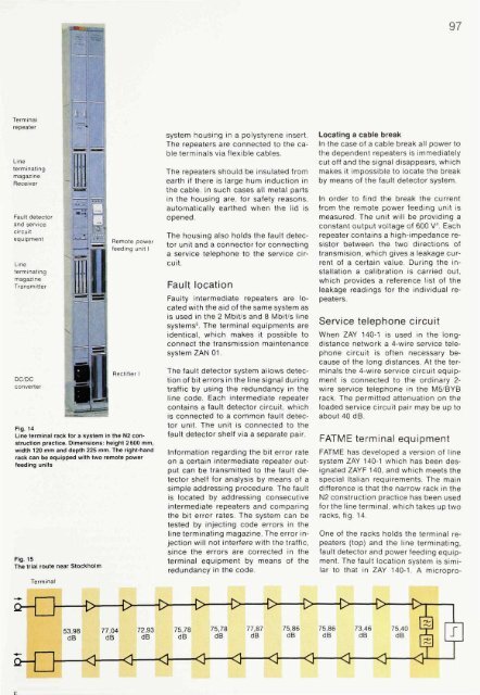
Fig. 14<br />
Line terminal rack <strong>for</strong> a <strong>system</strong> in the N2 construction<br />
practice. Dimensions: height 2 600 mm,<br />
width 120 mm and depth 225 mm. The right-hand<br />
rack can be equipped with two remote power<br />
feeding units<br />
Fig. 15<br />
The trial route near Stockholm<br />
<strong>system</strong> housing in a polystyrene insert.<br />
The repeaters are connected to the cable<br />
terminals via flexible cables.<br />
The repeaters should be insulated from<br />
earth if there is large hum induction in<br />
the cable. In such cases all metal parts<br />
in the housing are, <strong>for</strong> safety reasons,<br />
automatically earthed when the lid is<br />
opened.<br />
The housing also holds the fault detector<br />
unit and a connector <strong>for</strong> connecting<br />
a service <strong>telephone</strong> to the service circuit.<br />
Fault location<br />
Faulty intermediate repeaters are located<br />
with the aid of the same <strong>system</strong> as<br />
is used in the 2 Mbit/s and 8 Mbit/s line<br />
<strong>system</strong>s 5 . The terminal equipments are<br />
identical, which makes it possible to<br />
connect the transmission maintenance<br />
<strong>system</strong> ZAN 01.<br />
The fault detector <strong>system</strong> allows detection<br />
of bit errors in the line signal during<br />
traffic by using the redundancy in the<br />
line code. Each intermediate repeater<br />
contains a fault detector circuit, which<br />
is connected to a common fault detector<br />
unit. The unit is connected to the<br />
fault detector shelf via a separate pair.<br />
In<strong>for</strong>mation regarding the bit error rate<br />
on a certain intermediate repeater output<br />
can be transmitted to the fault detector<br />
shelf <strong>for</strong> analysis by means of a<br />
simple addressing procedure. The fault<br />
is located by addressing consecutive<br />
intermediate repeaters and comparing<br />
the bit error rates. The <strong>system</strong> can be<br />
tested by injecting code errors in the<br />
line terminating magazine. The error injection<br />
will not interfere with the traffic,<br />
since the errors are corrected in the<br />
terminal equipment by means of the<br />
redundancy in the code.<br />
Locating a cable break<br />
In the case of a cable break all power to<br />
the dependent repeaters is immediately<br />
cut off and the signal disappears, which<br />
makes it impossible to locate the break<br />
by means of the fault detector <strong>system</strong>.<br />
In order to find the break the current<br />
from the remote power feeding unit is<br />
measured. The unit will be providing a<br />
constant output voltage of 600 V 4 . Each<br />
repeater contains a high-impedance resistor<br />
between the two directions of<br />
transmision, which gives a leakage current<br />
of a certain value. During the installation<br />
a calibration is carried out,<br />
which provides a reference list of the<br />
leakage readings <strong>for</strong> the individual repeaters.<br />
Service <strong>telephone</strong> circuit<br />
When ZAY 140-1 is used in the longdistance<br />
network a 4-wire service <strong>telephone</strong><br />
circuit is often necessary because<br />
of the long distances. At the terminals<br />
the 4-wire service circuit equipment<br />
is connected to the ordinary 2-<br />
wire service <strong>telephone</strong> in the M5/BYB<br />
rack. The permitted attenuation on the<br />
loaded service circuit pair may be up to<br />
about 40 dB.<br />
FATME terminal equipment<br />
FATME has developed a version of line<br />
<strong>system</strong> ZAY 140-1 which has been designated<br />
ZAYF 140, and which meets the<br />
special Italian requirements. The main<br />
difference is that the narrow rack in the<br />
N2 construction practice has been used<br />
<strong>for</strong> the line terminal, which takes up two<br />
racks, fig. 14.<br />
One of the racks holds the terminal repeaters<br />
(top) and the line terminating,<br />
fault detector and power feeding equipment.<br />
The fault location <strong>system</strong> is similar<br />
to that in ZAY 140-1. A micropro-


