

diavox courier 700, digital system telephone for md 110 data
diavox courier 700, digital system telephone for md 110 data
diavox courier 700, digital system telephone for md 110 data

Create successful ePaper yourself
Turn your PDF publications into a flip-book with our unique Google optimized e-Paper software.
ERICSSON<br />
REVIEW<br />
2 1982<br />
DIAVOX COURIER <strong>700</strong>, DIGITAL SYSTEM TELEPHONE FOR MD <strong>110</strong><br />
DATA COMMUNICATIONS IN MD <strong>110</strong><br />
MINI-LINK 15<br />
AXB 30-A PUBLIC DATA NETWORK SYSTEM<br />
140MBIT/S LINE SYSTEM<br />
CCITT SIGNALLING SYSTEM NO. 7 IN AXE 10<br />
OPTICAL TRANSMISSION LINK IN ATC SYSTEMS<br />
THE RAILWAY TRAFFIC IN MELBOURNE
ERICSSON REVIEW<br />
NUMBER 2 • 1982 • VOLUME 59<br />
Copyright Telefonaktiebolaget LM Ericsson<br />
Printed in Sweden, Stockholm 1982<br />
RESPONSIBLE PUBLISHER GOSTA LINDBERG<br />
EDITOR GOSTA NEOVIUS<br />
EDITORIAL STAFF FOLKE BERG<br />
DISTRIBUTION GUSTAF 0 DOUGLAS<br />
ADDRESS S-12625 STOCKHOLM, SWEDEN<br />
SUBSCRIPTION ONE YEAR $12,000 ONE COPY $3 00<br />
PUBLISHED IN SWEDISH, ENGLISH, FRENCH<br />
AND SPANISH WITH FOUR ISSUES PER YEAR<br />
THE ARTICLES MAY BE REPRODUCED<br />
AFTER CONSULTATION WITH THE EDITOR<br />
Contents<br />
58<br />
67<br />
76<br />
82<br />
91<br />
100<br />
106<br />
115<br />
DIAVOX Courier <strong>700</strong>, Digital System Telephone <strong>for</strong> MD <strong>110</strong><br />
Data Communications in MD <strong>110</strong><br />
MINI-LINK 15<br />
AXB 30-A Public Data Network System<br />
140 Mbit/s Line System<br />
CCITT Signalling System No. 7 in AXE 10<br />
Optical Transmission Link in ATC Systems<br />
The Railway Traffic in Melbourne<br />
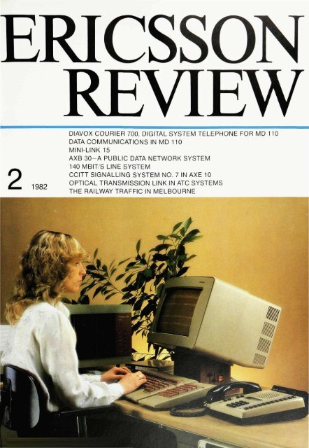
COVER<br />
Operator's position with equipment <strong>for</strong> word and<br />
text processing, <strong>for</strong> communication over external<br />
networks using telex and teletex, and with access<br />
to central ADP <strong>system</strong>s
DIAVOX Courier <strong>700</strong>, Digital System<br />
Telephone <strong>for</strong> MD <strong>110</strong><br />
Jonas Reinius and Olof Sandstrom<br />
MD <strong>110</strong> is a <strong>digital</strong> SPC-PABX <strong>for</strong> 100 to 10000 extensions. A general description<br />
of MD <strong>110</strong> and description of the <strong>digital</strong> signal processing in the <strong>system</strong> were<br />
provided in two articles in the previous number of this publication' 2 . In addition<br />
to analog, conventional <strong>telephone</strong>s it is also possible to connect <strong>digital</strong> <strong>system</strong><br />
<strong>telephone</strong>s, designation DIAVOX Courier <strong>700</strong>. to MD <strong>110</strong>. In this article the<br />
authors describe the design of <strong>digital</strong> <strong>system</strong> <strong>telephone</strong> DIAVOX Courier <strong>700</strong>. the<br />
facilities it provides and some application fields.<br />
UDC621 395.6.037.37<br />
With a <strong>digital</strong> <strong>telephone</strong> like <strong>system</strong><br />
<strong>telephone</strong> DIAVOX Courier <strong>700</strong> it is possible<br />
to simplify some of the functions<br />
available with a conventional <strong>telephone</strong>.<br />
Numerous new extension facilities<br />
can also be introduced. It is thereby<br />
possible to attain a heavy traffic handling<br />
volume and an excellent overview<br />
of ongoing, camped-on and queuing<br />
calls. Flexible programming routines<br />
permit the functions of DIAVOX Courier<br />
<strong>700</strong> to be adapted to the individual requirements<br />
of each user. Extension<br />
user facilities that previously required<br />
several <strong>telephone</strong> <strong>system</strong>s e.g. intercom,<br />
line pickup, queuing and diversion,<br />
can now be incorporated in the<br />
same <strong>telephone</strong>. Data communication<br />
facilities, that previously required a parallel<br />
network can now be integrated in<br />
MD <strong>110</strong> with DIAVOX Courier <strong>700</strong>.<br />
DIAVOX Courier <strong>700</strong><br />
DIAVOX Courier <strong>700</strong>, <strong>digital</strong> <strong>system</strong> <strong>telephone</strong><br />
<strong>for</strong> MD <strong>110</strong>, is a member of the<br />
DIAVOX family and utilizes the new.<br />
modular <strong>telephone</strong> design Courier. The<br />
design is modular in the sense that the<br />
same basic tools, complemented with<br />
add-on modules <strong>for</strong> different sizes, are<br />
used in the manufacture of the mechanical<br />
parts. Courier utilizes the same<br />
handset as the other <strong>telephone</strong>s in the<br />
DIAVOX family.<br />
Initially, <strong>digital</strong> <strong>system</strong> <strong>telephone</strong>s will<br />
be available in two versions, with one<br />
alternatively three rows, each row containing<br />
12 function fields. Each field has<br />
a button, an associated light emitting<br />
Fig. 1<br />
Variants of the MD <strong>110</strong> <strong>digital</strong> <strong>system</strong> <strong>telephone</strong><br />
DIAVOX Courier <strong>700</strong> with one and three rows of<br />
function fields
59<br />
JONAS REINIUS<br />
ELLEMTEL Utvecklings AB<br />
OLOF SANDSTROM<br />
Communication Systems Division<br />
Ericsson In<strong>for</strong>mation Systems AB<br />
Fig. 2<br />
Block diagram <strong>for</strong> DIAVOX Courier <strong>700</strong><br />
diode, LED, and designation strip. It is a<br />
simple matter to remove and replace<br />
the designation strip <strong>for</strong> an entire row,<br />
fig. 1.<br />
Digital <strong>system</strong> <strong>telephone</strong> functions<br />
The two versions of DIAVOX Courier <strong>700</strong><br />
that will be available initially contain the<br />
following:<br />
- handset<br />
- voice controlled loudspeaker function<br />
with adjustable volume, connection<br />
button and privacy button<br />
- tone ringer with three different<br />
characters and two levels, alternatively<br />
switched off<br />
- 18 character, 7 segment liquid crystal<br />
display, LCD<br />
- pushbutton unit <strong>for</strong> dialling calls<br />
- function buttons <strong>for</strong> disconnection,<br />
transfer and switching to programming<br />
mode<br />
- three function fields <strong>for</strong> own line,<br />
triple access line<br />
- 8 alternatively 32 function fields <strong>for</strong><br />
programmable functions, depending<br />
on the size of the <strong>telephone</strong><br />
- jack <strong>for</strong> tape recorder<br />
- jack <strong>for</strong> "don't disturb" indicator (<strong>for</strong><br />
doorpost signals)<br />
- jack <strong>for</strong> connection of Data Circuit<br />
terminating Equipment, DCE.<br />
Design<br />
The <strong>digital</strong> <strong>system</strong> <strong>telephone</strong>, whose<br />
block diagram can be seen in fig. 2,<br />
receives a 48 V low-ohmic feed from the<br />
line circuit. Feeding is supervised and<br />
disconnected when the line is shortcircuited.<br />
The signal on the line is led via a<br />
trans<strong>for</strong>mer into a specially designed<br />
CMOS-circuit. The latter contains all<br />
logic required <strong>for</strong> line transmission and<br />
signal word <strong>for</strong>matting. The circuit is<br />
designated BSA (Burst Signalling<br />
Adapter). BSA can be programmed as<br />
controller on the line circuit or as slave<br />
in the <strong>telephone</strong>. PCM-<strong>data</strong> is fed from<br />
the BSA-circuit directly to codec and<br />
filter, which in their turn are connected<br />
to the voice part of the <strong>digital</strong> <strong>system</strong><br />
<strong>telephone</strong>.<br />
Connection<br />
Transmission is <strong>digital</strong> which provides<br />
the following advantages:<br />
- voice and <strong>data</strong> communications as<br />
well as line signalling can take place<br />
on the same extension line independently<br />
of one another<br />
- non-attenuated voice transmission,<br />
irrespective of line length<br />
- the transmission characteristics are<br />
identical to those <strong>for</strong> a four wire connection.<br />
The <strong>digital</strong> <strong>system</strong> telehone has a twowire<br />
connection, fig. 3, which allows<br />
existing cable networks <strong>for</strong> analog extension<br />
<strong>telephone</strong>s to be used on<br />
changeover to a <strong>digital</strong> <strong>system</strong> <strong>telephone</strong>,<br />
even when the latter has a <strong>data</strong><br />
terminal connected. This can save time<br />
and money.
Fig. 4<br />
Principle <strong>for</strong> burst signalling. Each burst consists<br />
of 12 bits bi-phase-coded in<strong>for</strong>mation. The biphase<br />
frequency is 256 kbit/s.<br />
F<br />
D<br />
S<br />
P<br />
Frame synchronization bit<br />
Data in<strong>for</strong>mation<br />
Line signalling in<strong>for</strong>mation<br />
Voice inlormation (PCM)<br />
Message<br />
Fig. 5<br />
Principle <strong>for</strong> line signalling. Each signal word is<br />
composed from the line signalling bit from each<br />
of 11 consecutive bursts. The message is <strong>for</strong>med<br />
from minimum 4 and maximum 23 signal words.<br />
To check transmission the signal word has start/<br />
stop <strong>for</strong>mat with parity check and the first word of<br />
the message is length in<strong>for</strong>mation and the last<br />
word a check sum<br />
Signalling<br />
All signals between MD <strong>110</strong> and the<br />
<strong>digital</strong> <strong>system</strong> <strong>telephone</strong> are exchanged<br />
in <strong>digital</strong> <strong>for</strong>m, in bursts, fig. 4. The<br />
extension line unit, ELU-D, sends a 12<br />
bit burst at a transmission speed of 256<br />
kbit/s every 125 us. The <strong>telephone</strong> is<br />
synchronized with this rate so that it<br />
sends its burst after receiving a burst.<br />
The delay between transmitted and received<br />
burst in the line unit of the PABX<br />
depends on the line delay. Burst length,<br />
repetition frequency and delay combined<br />
limit the length of the line to<br />
about 2,000 metres <strong>for</strong> this signalling<br />
method. Other factors such as current<br />
feed, signal attenuation and disturbances<br />
limit the range to about 1,000<br />
metres.<br />
The line transmission function utilizes<br />
three mutually independent, bothway<br />
channels <strong>for</strong>:<br />
- voicetransmissionat a rate of64 kbit/s<br />
with one PCM-sample per burst<br />
- line signals at a rate of 8 kbit s with<br />
one bit per burst. A signal word is<br />
composed of the signal bits from 11<br />
consecutive bursts and consists of 8<br />
bits signal in<strong>for</strong>mation plus synchronization<br />
and parity bits. fig. 5. The<br />
signal words are assembled into messages<br />
of varying lengths The message<br />
contains check in<strong>for</strong>mation in<br />
the <strong>for</strong>m of message length and<br />
check sum. The receiver acknowledges<br />
the message after first approving<br />
it. Retransmission takes place if a<br />
fault exists. A message can be "raised<br />
handset from the <strong>telephone</strong> or<br />
"light LED with call flashing and start<br />
tone ringer" to the <strong>telephone</strong><br />
- <strong>data</strong> transmission at a rate of 16 kbit/s<br />
with two bits per burst, a <strong>data</strong> flow<br />
that is processed in the auxiliary unit<br />
attached to the <strong>telephone</strong>.<br />
The line transmission also includes synchronization<br />
with 8 kbit/s, two half bits<br />
per burst.<br />
The line signals proceed word by word<br />
between the BSA-circuit and the <strong>telephone</strong>'s<br />
CMOS-microcomputer. The<br />
latter is responsible <strong>for</strong> the line signalling<br />
i.e. it deals with the signalling protocol,<br />
checking the received messages<br />
and time supervision <strong>for</strong> acknowledgement<br />
of transmitted messages. The microcomputer<br />
also controls the scanning<br />
of button and hookswitch signals,<br />
cadences <strong>for</strong> LEDs and character transfer<br />
to the 18 character LCD.<br />
The <strong>digital</strong> <strong>system</strong> <strong>telephone</strong> does not<br />
possess its own storage function <strong>for</strong><br />
abbreviated dialling or other facilities;<br />
all <strong>data</strong> <strong>for</strong> these are stored in MD <strong>110</strong><br />
Only cadences <strong>for</strong> tone ringers. LED<br />
and LCD signals are stored in the <strong>telephone</strong>.<br />
These are programmed on installation.<br />
Indications<br />
The <strong>digital</strong> <strong>system</strong> <strong>telephone</strong> has optical<br />
and acoustic indications. Each function<br />
field has an associated LED that<br />
can display five different states, fig. 6, in<br />
order to provide the user with as clear<br />
and detailed a picture as possible <strong>for</strong><br />
each traffic function. The 18 character<br />
LCD is normally divided into three fields<br />
to provide the user with in<strong>for</strong>mation<br />
about numerous different situations in<br />
an unequivocal manner, fig, 7. For example,<br />
on an incoming call to the user's<br />
own line, triple access line, the caller's<br />
identity is displayed in the left field of<br />
the LCD be<strong>for</strong>e the user answers. On<br />
answer the caller s number moves to<br />
the right field and the left is blanked.<br />
Ring signals are issued by tone ringing<br />
MDF<br />
Fig. 3<br />
Connection of DIAVOX Courier <strong>700</strong> via normal<br />
extension line
Fig. 6, left<br />
Example showing optical signals <strong>for</strong> the function<br />
field LED<br />
Fig. 8, right<br />
Example showing cadences <strong>for</strong> tone ringer<br />
Fig. 7a<br />
The use of the fields of the LCD<br />
X<br />
Y<br />
Z<br />
Calling party<br />
Diverted or dialled party<br />
Called party, connected conversation party<br />
Fig. 7b<br />
Example of what the LCD can show in various<br />
traffic cases<br />
in the <strong>telephone</strong> loudspeaker. The <strong>digital</strong><br />
<strong>system</strong> <strong>telephone</strong> user can program<br />
one of five ring alternatives <strong>for</strong> each<br />
traffic function, namely; no ring signal,<br />
ring signal after delay, first ring signal<br />
(muted) only and one ring signal<br />
(muted) only after delay. Incoming calls<br />
during an ongoing conversation are announced<br />
by the first ring signal (muted)<br />
only.<br />
The tone ringer has three different cadences<br />
with which to announce internal<br />
calls, external calls and automatic callback,<br />
fig. 8. Each extension can select<br />
one of three different signal characters<br />
on the <strong>digital</strong> <strong>system</strong> <strong>telephone</strong>. This is<br />
helpful if there is more than one <strong>telephone</strong><br />
in the room. It is also possible to<br />
choose between a loud signal, muted<br />
signal or disconnecting ringing completely.<br />
Traffic facilities<br />
A number of new traffic facilities have<br />
been defined <strong>for</strong> the MD <strong>110</strong> <strong>digital</strong> <strong>system</strong><br />
<strong>telephone</strong>. These make possible<br />
the inclusion in one <strong>system</strong> of facilities<br />
that previously demanded several parallel<br />
communication <strong>system</strong>s. Furthermore<br />
some functions have been simplified,<br />
<strong>for</strong> example a complicated procedure<br />
has been reduced to a single<br />
button depression.<br />
Outgoing calls can be initiated from a<br />
<strong>digital</strong> <strong>system</strong> <strong>telephone</strong> by:<br />
- lifting the handset, waiting <strong>for</strong> tone<br />
and dialling the reguired number precisely<br />
as with a conventional <strong>telephone</strong><br />
- pressing the loudspeaker button,<br />
waiting <strong>for</strong> tone from the loudspeaker<br />
and dialling the number<br />
- dialling the number directly by pressing<br />
the digit buttons without waiting<br />
<strong>for</strong> tone. After the entire number has<br />
been dialled a tone message indicating<br />
that the called party is free, busy<br />
etc. is received via the loudspeaker<br />
- pressing a traffic function button,<br />
waiting <strong>for</strong> tone in the loudspeaker<br />
and dialling the number in te normal<br />
manner.<br />
When the user lifts the handset the <strong>digital</strong><br />
<strong>system</strong> <strong>telephone</strong> is switched from<br />
the loudspeaking to the normal voice<br />
mode.<br />
Note: 1000 diverted to 6000, 2000 diverted to 3000<br />
An incoming call is indicated with rapid<br />
flashing on a function field LED and can<br />
be answered by:<br />
- lifting the handset or pressing the<br />
loudspeaker button if the call is to the<br />
extension user's own line, triple access<br />
line<br />
- pressing the traffic function button<br />
that indicates the call, accepting the<br />
call in the loudspeaker mode and<br />
then, if desired, switching to normal<br />
voice mode by lifting the handset.
New traffic facilities<br />
Triple access line corresponds to the<br />
extension line of a conventional <strong>telephone</strong>.<br />
Each <strong>digital</strong> <strong>system</strong> <strong>telephone</strong><br />
has one and only one triple access line.<br />
This line is represented on the <strong>system</strong><br />
<strong>telephone</strong> by three function fields, and<br />
thus has three separate connection<br />
possibilities. An extension can namely<br />
be free <strong>for</strong> new calls despite one connection<br />
possibility already being seized.<br />
When the new call is answered the<br />
ongoing call is parked. Two connection<br />
possibilities have now been seized, one<br />
<strong>for</strong> parking and one <strong>for</strong> conversation.<br />
To facilitate transfer of the latter call the<br />
third connection possibility, <strong>for</strong> outgoing<br />
calls, is used and three connection<br />
possibilities are seized, two <strong>for</strong> parking<br />
and one <strong>for</strong> conversation. A prerequisite<br />
<strong>for</strong> the <strong>digital</strong> <strong>system</strong> <strong>telephone</strong><br />
to be free <strong>for</strong> incoming calls is that a<br />
free connection possibility (field) exists<br />
<strong>for</strong> inquiry and that no unanswered, incoming<br />
call to the triple access line<br />
already exists, fig. 9.<br />
Data line facilitates establishment of<br />
<strong>data</strong> communication irrespective of<br />
ongoing voice communication. All<br />
states are indicated optically only, in<br />
order not to disturb ongoing conversation.<br />
For an outgoing call the <strong>data</strong><br />
line button is pressed whereupon the<br />
LED double flashes to indicate dialling<br />
state. The B-number, external or internal,<br />
is dialled in the normal manner. The<br />
<strong>data</strong> line LED on the called party's <strong>telephone</strong><br />
flashes rapidly to indicate a call.<br />
When he answers the switch to <strong>data</strong><br />
mode ensues and the rapid flashing of<br />
the LED changes to a steady glow. If the<br />
called party is busy this is indicated to<br />
the caller by rapid flashing on the DCE<br />
and the caller can disconnect or campon,<br />
fig. 10.<br />
Extra line. A <strong>digital</strong> <strong>system</strong> <strong>telephone</strong><br />
can have an arbitrary number of extra<br />
lines, only the quantity of function fields<br />
is a limiting factor. The free states of the<br />
extra lines do not affect and are not<br />
affected by the free state of the triple<br />
access line, fig. 11.<br />
Line pickup is the name of the traffic<br />
facility that allows the triple access line<br />
or extra line of a <strong>digital</strong> <strong>system</strong> <strong>telephone</strong><br />
to be represented in the <strong>digital</strong><br />
<strong>system</strong> <strong>telephone</strong> of another extension,<br />
e.g. <strong>for</strong> call diversion. The facility is<br />
used <strong>for</strong> incoming and outgoing calls. A<br />
line can be represented <strong>for</strong> line pickup<br />
purposes in up to 30 other <strong>digital</strong> <strong>system</strong><br />
<strong>telephone</strong>s, fig. 12.<br />
Dedicated intercom link can be regarded<br />
as a direct connection between<br />
two <strong>digital</strong> <strong>system</strong> <strong>telephone</strong>s that cannot<br />
encounter busy state although congestion<br />
state is possible. The called party<br />
knows immediately who is calling as<br />
the callers name is on the designation<br />
strip adjacent to the LED, fig. 13. If the<br />
extension has programmed the<br />
dedicated intercom link <strong>for</strong> immediate<br />
voice connection then the same function<br />
as <strong>for</strong> intercom calls is obtained.<br />
If A calls B and receives no answer he<br />
can in<strong>for</strong>m B that he has called by causing<br />
the appropriate LED on B's <strong>telephone</strong><br />
to flash in a special manner.<br />
Fig. 12<br />
Line pickup facility
Fig. 15, left<br />
Common bell call pickup facility<br />
Fig. 16, right<br />
Voice paging facility<br />
Fig. 17<br />
Automatic Call Distribution (ACD) facility<br />
If B is already busy with a call and prefers<br />
to answer the call later, he can<br />
advise A accordingly by pressing a button<br />
which gives A the appropriate tone<br />
message while B's LED starts flashing<br />
in a special manner as a reminder to call<br />
A later.<br />
Exclusive external line is similar to a<br />
separate <strong>telephone</strong> subscription. A<br />
trunk line is reserved <strong>for</strong> each exclusive<br />
external line. This can be represented in<br />
up to 30 <strong>digital</strong> <strong>system</strong> <strong>telephone</strong>s. Incoming<br />
calls are indicated directly on<br />
the <strong>telephone</strong>s. For outgoing calls the<br />
trunk line is through-connected towards<br />
the <strong>digital</strong> <strong>system</strong> <strong>telephone</strong> and<br />
the extension user can dial the external<br />
number directly without route access<br />
code.<br />
A typical beneficiary of the exclusive<br />
external line facility is an executive with<br />
many external calls and a secretary<br />
serving as divertee position, fig. 14.<br />
Common bell call pickup (or line pickup<br />
group). Instead of a common bell a<br />
function field on the <strong>digital</strong> <strong>system</strong> <strong>telephone</strong><br />
is used. Each <strong>digital</strong> <strong>system</strong> <strong>telephone</strong><br />
can serve up to five of these<br />
groups. As long as a call queue exists<br />
this fact is indicated on the appropriate<br />
LED on all <strong>digital</strong> <strong>system</strong> <strong>telephone</strong>s,<br />
maximum 30, in which the group is represented.<br />
On answer the call is switched<br />
to the answering extensions triple access<br />
line. This facility is used e.g. by<br />
travel agencies <strong>for</strong> booking tickets, fig.<br />
15.<br />
Voice paging facilitates loudspeaking<br />
messages via a defined group of <strong>digital</strong><br />
<strong>system</strong> <strong>telephone</strong>s. The same facility<br />
exists in intercom <strong>system</strong>s. Short messages<br />
can be issued e.g. "Visitor <strong>for</strong> Mr.<br />
Smith at the reception desk".<br />
The paging call is transmitted to the<br />
loudspeaking <strong>digital</strong> <strong>system</strong> <strong>telephone</strong>s<br />
that are programmed <strong>for</strong> this facility<br />
and whose voice channel is free. Paging<br />
can be combined via an optical call<br />
indication on the appropriate LED of<br />
those <strong>digital</strong> <strong>system</strong> <strong>telephone</strong>s that<br />
have this facility. Up to 30 <strong>digital</strong> <strong>system</strong><br />
<strong>telephone</strong>s can be members of each<br />
group.<br />
On depression of the button to initiate<br />
voice paging a tone burst with special<br />
character is issued <strong>for</strong> one second,<br />
whereafter the pager leaves a message.<br />
The pager then releases the button in<br />
order to disconnect the microphone.<br />
The call lasts <strong>for</strong> 20 seconds. During<br />
this period an extension in the group<br />
can answer by pressing the appropriate<br />
button. The call that is thereby established<br />
seizes the triple access lines of<br />
both parties, fig. 16.<br />
Automatic call distribution is similar to<br />
common bell call pickup, but the call is<br />
routed to one extension only. Up to five<br />
groups with a total of 30 extensions can<br />
exist. Each group has a call number.<br />
Extensions can be members of several<br />
groups. An incoming call is distributed<br />
to the group member, extension, indicated<br />
as on duty and who has been free<br />
longest.
64<br />
Fig. 18<br />
Single button access facility<br />
The queue lengths of those groups represented<br />
on the <strong>digital</strong> <strong>system</strong> <strong>telephone</strong><br />
of a free, on duty extension are<br />
shown on the appropriate LEDs. The<br />
extension user can indicate himself on<br />
duty in any number of the groups in<br />
which he is a member. The on duty state<br />
is indicated by a steadily glowing LED<br />
and a call by e.g. a rapidly flashing LED.<br />
On answer the established call seizes<br />
the triple access line. Fig. 17 provides<br />
an example of LED in<strong>for</strong>mation. This<br />
extension should switch immediately to<br />
the on duty state <strong>for</strong> the alarm number<br />
as this queue has grown.<br />
Single button access functions as an<br />
individual abbreviated number with up<br />
to 20 digits. The extension user programs<br />
the number in<strong>for</strong>mation with the<br />
<strong>digital</strong> <strong>system</strong> <strong>telephone</strong> in the programming<br />
mode. The stored number<br />
in<strong>for</strong>mation can also constitute a prefix<br />
or suffix digit or entire procedures with<br />
* and # to access facilities more simply.<br />
Outgoing calls initiated with single button<br />
access seize the triple access line or<br />
the traffic facility that has already been<br />
activated and dial tone is obtained on<br />
depression of the single button access<br />
button, fig. 18.<br />
All function fields in the <strong>digital</strong> <strong>system</strong><br />
<strong>telephone</strong> have the single button access<br />
facility as basic function, be<strong>for</strong>e<br />
they are assigned any other traffic facility<br />
from the l/O-terminal.<br />
Other new facilities<br />
Group parking with call pickup function<br />
means that a call can be parked by one<br />
<strong>digital</strong> <strong>system</strong> <strong>telephone</strong> and admitted<br />
to another in which the facility is represented,<br />
like line pickup or another extension<br />
user's exclusive external line.<br />
Immediate voice connection (or handsfree<br />
automatic answer) is a facility that<br />
the extension user can program from<br />
the <strong>digital</strong> <strong>system</strong> <strong>telephone</strong>. Each traffic<br />
facility can be assigned this facility<br />
individually, which is particularly suitable<br />
<strong>for</strong> dedicated intercom link and the<br />
user obtains facilities similar to those<br />
available with intercom <strong>system</strong>s.<br />
Diary shows the year, month, day, hour<br />
and minute on the LCD when the diary<br />
button is pressed.<br />
Message waiting is a facility, that <strong>for</strong> the<br />
called party, stores the numbers of<br />
those extensions that have placed a<br />
callback order against the called party's<br />
triple access line after meeting no answer.<br />
The message waiting LED lights<br />
to show that one or more stored messages<br />
exist. On return an extension user<br />
whose message waiting LED is lit can<br />
glance through the list of stored numbers<br />
to learn who has called, and automatically<br />
call these parties, one at a<br />
time, by pressing the message waiting<br />
button.<br />
External number redial. An extension<br />
user can store the dialled external number<br />
by pressing the function button and<br />
transmit this number at any time by<br />
pressing the same button.<br />
Programming mode. Extension users<br />
can place the <strong>digital</strong> <strong>system</strong> <strong>telephone</strong><br />
in the programming mode and in this<br />
state check and program their single<br />
button access numbers and call alternatives<br />
<strong>for</strong> other traffic facilities.<br />
Fig. 19<br />
Divertee position facility
E<br />
65<br />
Dedicated function fields<br />
Certain facilities, that in conventional<br />
<strong>telephone</strong>s require a complicated execution<br />
procedure, have been given a<br />
simpler routine in the <strong>digital</strong> <strong>system</strong><br />
<strong>telephone</strong> by assigning the facility a<br />
dedicated function field.<br />
Automatic callback is assigned a function<br />
field from which automatic callback<br />
is initiated and answered. The<br />
function button LED glows steadily as<br />
long as any callback remains. On an<br />
incoming callback the LED flashes <strong>for</strong> a<br />
call. After answer the conversation is<br />
held on the triple access line.<br />
Diversion is assigned a function field,<br />
from which "diversion direct" and "diversion<br />
follow-me" are ordered and<br />
cancelled. The function field LED glows<br />
when the <strong>digital</strong> <strong>system</strong> <strong>telephone</strong> is<br />
diverted.<br />
Applications<br />
By assigning <strong>digital</strong> <strong>system</strong> <strong>telephone</strong>s<br />
different combinations of the facilities<br />
described above it is possible to create<br />
different application <strong>system</strong>s, that can<br />
be optimized to the traffic requirements<br />
of individual users. Some application<br />
examples follow below.<br />
Divertee position<br />
Effective supervision of a large number<br />
of extensions in the diverted state is<br />
obtained by equipping the supervision<br />
position, divertee position, with one or<br />
more <strong>digital</strong> <strong>system</strong> <strong>telephone</strong>s. Both<br />
caller and called party can be identified<br />
on the LCD. Simple parking and extending<br />
procedures are obtained with function<br />
buttons, and an even distribution of<br />
traffic <strong>for</strong> several <strong>telephone</strong>s is<br />
achieved by extension group hunting or<br />
common bell call pickup, fig. 19.<br />
The MD <strong>110</strong> <strong>digital</strong> <strong>system</strong> <strong>telephone</strong><br />
can also be used as a divertee position<br />
<strong>for</strong> up to 32 extensions, where every<br />
extension is represented by a function<br />
field. The associated LEDs provide continuous<br />
in<strong>for</strong>mation on the state of each<br />
diverted extension, e.g. incoming call,<br />
busy, parked. The ring signal <strong>for</strong> the<br />
lines of the diverted extensions can be<br />
delayed so that the divertee position<br />
receives a signal only if the call remains<br />
unanswered after a predetermined<br />
period.<br />
Executive/secretary facility<br />
This facility is built up by supplementing<br />
the divertee position facility with<br />
dedicated intercom link and line pickup<br />
group <strong>for</strong> those extensions <strong>for</strong> which<br />
Fig. 20<br />
Executive/secretary facility
special handling and supervision of<br />
traffic is desirable. This gives a secretary<br />
access to an executive's triple access<br />
line and exclusive external lines.<br />
The secretary can answer incoming<br />
calls, establish an inquiry call to the<br />
executive with the dedicated intercom<br />
link and then transfer the call if so desired.<br />
Ordered, outgoing calls can be transferred<br />
easily using this range of facilities,<br />
fig. 20.<br />
Intercom<br />
By combining the dedicated intercom<br />
link and the loudspeaking immediate<br />
voice connection facilities an intercom<br />
facility <strong>for</strong> up to 32 extensions is obtained.<br />
Several extensions can be called<br />
simultaneously using the voice paging<br />
facility, fig. 12.<br />
Line pickup group<br />
A line pickup group is <strong>for</strong>med through<br />
the representation of exclusive external<br />
line, triple access line or extra line in<br />
several <strong>digital</strong> <strong>system</strong> <strong>telephone</strong>s. Each<br />
<strong>digital</strong> <strong>system</strong> <strong>telephone</strong> in the group<br />
has each line represented by a function<br />
field. The extension user obtains a continuous<br />
picture of the current traffic situation<br />
in that the state of the lines is<br />
displayed on all <strong>telephone</strong>s in the<br />
group.<br />
An incoming call is thus signalled to the<br />
entire group and can be answered from<br />
any <strong>telephone</strong>. After answer the line is<br />
indicated as busy on the other <strong>telephone</strong>s.<br />
The call can now be transferred<br />
to another extension inside or outside<br />
the group, or parked with the indication<br />
"available <strong>for</strong> group pickup", whereafter<br />
any extension in the group can answer<br />
the parked call.<br />
Voice paging can be utilized and the<br />
person answering a call can in<strong>for</strong>m the<br />
group which member is being paged.<br />
Normal office extension<br />
The <strong>digital</strong> <strong>system</strong> <strong>telephone</strong> is used as<br />
a normal office extension primarily to<br />
simplify communications. By programming<br />
the single button access button of<br />
the <strong>digital</strong> <strong>system</strong> <strong>telephone</strong> with procedure<br />
codes it is possible to utilize a<br />
number of extension facilities merely by<br />
pressing a single button.<br />
The majority of the traffic facilities available<br />
to the <strong>digital</strong> <strong>system</strong> <strong>telephone</strong> can<br />
be used to advantage by a normal office<br />
extension. Particularly beneficial is the<br />
<strong>data</strong> line facility, that is not available to<br />
extension users with conventional <strong>telephone</strong>s,<br />
fig. 21.<br />
Operation and maintenance<br />
One great advantage provided by the<br />
two wire connection is that the existing<br />
line network can be used when a <strong>digital</strong><br />
sysem <strong>telephone</strong> is introduced. The<br />
conventional <strong>telephone</strong> is unjacked and<br />
the <strong>digital</strong> <strong>telephone</strong> is jacked in. On the<br />
PABX side it is necessary to switch from<br />
analog line circuit to <strong>digital</strong> line circuit<br />
in the main distribution frame, fig. 2.<br />
Each <strong>digital</strong> <strong>system</strong> <strong>telephone</strong> can be<br />
"tailored" <strong>for</strong> its user's requirements,<br />
i.e. via commands from the l/O-terminal<br />
it is possible <strong>for</strong> the user to gear to his<br />
own <strong>telephone</strong> those traffic facilities he<br />
requires. The <strong>digital</strong> <strong>system</strong> <strong>telephone</strong><br />
is prepared <strong>for</strong> <strong>data</strong> communications<br />
and has a jack at the back <strong>for</strong> connection<br />
of an adapter <strong>for</strong> a <strong>data</strong> terminal.<br />
The programs <strong>for</strong> the traffic facilities<br />
are stored in the PABX; only the marketdependent<br />
cadences <strong>for</strong> tone signals<br />
and <strong>for</strong> function field LEDs are stored in<br />
the memory of the <strong>digital</strong> <strong>system</strong> <strong>telephone</strong>.<br />
The <strong>telephone</strong> can be disconnected<br />
and reconnected or moved without<br />
losing its programmed traffic facilities.<br />
Digital <strong>system</strong> <strong>telephone</strong>s are fed from<br />
the PABX, and they can there<strong>for</strong>e also<br />
function during loss of the mains voltage.<br />
References<br />
1. Morlinger, R.: MD <strong>110</strong>~a Digital<br />
SPC-PABX. Ericsson Rev. 59<br />
(1982):1, pp. 2-13.<br />
2. Reinius, J. et al: Digital Signal Processing<br />
in MD <strong>110</strong>. Ericsson Rev.<br />
59(1982):1, pp. 14-21.<br />
3. Barnicoat, G. et al: Dafa Communications<br />
in MD <strong>110</strong>. Ericsson Rev.<br />
59 (1982):2, pp. 67-75.<br />
ias2
Data Communications in MD <strong>110</strong><br />
67<br />
Gregory Barnicoat, Lars Boman and Olof Ulander<br />
MD <strong>110</strong> is a PABX <strong>for</strong> 100 to 10,000 extensions It fulfils traditional requirements<br />
as regards telephony facilities and it is also an effective instrument in the<br />
increased use of <strong>data</strong> communications.<br />
The authors describe how the conventional two-wire PABX network with MD <strong>110</strong><br />
is made accessible <strong>for</strong> <strong>data</strong> and text communications also. Several of the<br />
facilities designed <strong>for</strong> <strong>data</strong> users are described and examples are provided<br />
showing how it is possible to realize some common applications with these<br />
facilities. A central feature in the utilization of the <strong>data</strong> facilities is the design of<br />
user facilities and operation and maintenance functions. These are there<strong>for</strong>e<br />
dealt with at length.<br />
The rationalization and <strong>data</strong> processing<br />
instances within a company plan <strong>for</strong><br />
continued and increased use of computerized<br />
aids. More and more office staff<br />
are given access to <strong>data</strong> terminals with<br />
which to pursue their duties. As a consequence,<br />
demands increase <strong>for</strong> effective<br />
administration and maintenance of<br />
the terminal network. In the long run it<br />
is not possible to supply a unique solution<br />
<strong>for</strong> each problem as continued rationalization<br />
also demands increased<br />
integration of the work process 1 .<br />
UDC 681.327.8:<br />
621.395.345<br />
Fig. 1<br />
MD <strong>110</strong> structure<br />
Office routines claim an increasingly<br />
larger slice of a company's outlay. Work<br />
can be rationalized and costs cut by<br />
utilizing various aids, available thanks<br />
to the rapid developments in different<br />
technical spheres.<br />
Among the various aids are machines<br />
<strong>for</strong> duplicating, telex and word processing<br />
and also computer programs <strong>for</strong><br />
e.g. wage routines and stock-keeping.<br />
They are all aimed at providing better<br />
solutions to the most acute problems<br />
and each problem has been optimized<br />
individually.<br />
Demands <strong>for</strong> a terminal network which<br />
is more general in application increase<br />
also as it is desired to access more<br />
users to more facilities and to utilize<br />
expensive equipment mutually with<br />
other users.<br />
The increasingly varying requirements<br />
in respect of <strong>data</strong> management and<br />
<strong>data</strong> processing make it more and more<br />
difficult to obtain complete <strong>system</strong> solutions<br />
from a single supplier. Effective<br />
integration of <strong>system</strong>s from different<br />
suppliers presupposes general usage of<br />
standards <strong>for</strong> functions and interfaces.<br />
Intensive ef<strong>for</strong>ts are also in progress<br />
within national and international standardization<br />
organizations and are successively<br />
providing better and better<br />
possibilities <strong>for</strong> interconnecting the various<br />
<strong>system</strong>s. It must there<strong>for</strong>e be possible<br />
continuously to adapt the <strong>system</strong>s<br />
introduced today to later developments<br />
and changes in standards. An essential<br />
requirement is that of effective maintenance.<br />
The most reliable <strong>system</strong> can be<br />
hit by faults, but the <strong>system</strong> must be<br />
designed so that the effects of the faults<br />
are limited, and possibilities must exist<br />
<strong>for</strong> rapidly locating and eliminating<br />
those faults that occur.<br />
The solution to <strong>data</strong> communication<br />
problems offered by a modern PABX,<br />
MD <strong>110</strong>, from Ericsson In<strong>for</strong>mation Systems,<br />
is described in this article.<br />
Technical description<br />
MD <strong>110</strong> is a <strong>digital</strong> microprocessor-controlled<br />
PABX with modular building<br />
blocks 2 . It consists of line interface modules,<br />
LIMs; in large installations interconnected<br />
via a central group switch,<br />
GS, fig. 1.
LARS BOMAN<br />
ELLEMTEL Utveckling AB<br />
GREGORY BARNICOAT<br />
OLOF ULANDER<br />
Communication Systems Division<br />
Ericsson In<strong>for</strong>mation Systems AB<br />
A LIM has a time switch with 512 time<br />
slots <strong>for</strong> voice and <strong>data</strong>. Each time slot<br />
has a capacity of 64 kbit/s. Each LIM can<br />
be equipped with an arbitrary combination<br />
of line units <strong>for</strong> analog <strong>telephone</strong>s<br />
and <strong>digital</strong> <strong>system</strong> <strong>telephone</strong>s 3 , PABX<br />
operator consoles, <strong>data</strong> terminals and<br />
lines towards the public network. A LIM<br />
can either function autonomously or interwork<br />
with other LIMs via 32 channel<br />
PCM links, directly or via GS, that is<br />
controlled by the connected LIMs. GS<br />
has a modular structure and can be<br />
dimensioned <strong>for</strong> up to 248 PCM links,<br />
each with a transmission speed of 2.048<br />
Mbit/s.<br />
The <strong>data</strong> channel<br />
The <strong>for</strong>mat in the <strong>data</strong> channel shown in<br />
fig. 4 is used to transmit user <strong>data</strong><br />
through MD <strong>110</strong>.<br />
The <strong>for</strong>mat is utilized both <strong>for</strong> <strong>data</strong><br />
transmission and to balance the speed<br />
between the connected terminal and<br />
the <strong>data</strong> channel. Empty frames are sent<br />
as filling, fig. 5, to balance the speed.<br />
The <strong>for</strong>mat facilitates asynchronous<br />
and synchronous transparent transmission<br />
of <strong>data</strong>. Modifier bits are used <strong>for</strong><br />
interface signals and some test and<br />
maintenance signals.<br />
Digital <strong>system</strong> <strong>telephone</strong>s, PABX operator<br />
consoles and <strong>data</strong> terminals are<br />
connected to a <strong>digital</strong> line unit board,<br />
ELU-D, that possesses eight line circuit<br />
functions and occupies 16 multiple positions<br />
in the switch, fig. 2. Normally<br />
eight time slots are used <strong>for</strong> voice channels<br />
and eight also <strong>for</strong> <strong>data</strong> channels.<br />
Two-wire extension lines are used. Digital<br />
units have a 96 kbit/s duplex connection<br />
with the PABX, achieved by time<br />
division multiplex burst signalling. The<br />
bursts are transmitted at a speed of 256<br />
kbit/s. They comprise 12 bits and carry<br />
<strong>digital</strong> signals as shown in fig. 3.<br />
Terminal connections<br />
Data terminal equipment, DCE-T, that is<br />
connected directly to the rear of the<br />
<strong>telephone</strong>, fig. 6, is used to adapt the<br />
<strong>digital</strong> <strong>system</strong> <strong>telephone</strong> to different<br />
physical and logic terminal interfaces.<br />
The bit flow from LIM is accepted and<br />
sorted in a customer-adapted LSI circuit.<br />
The 64 kbit/s channel proceeds via<br />
PCM coders and filters to the analog<br />
voice section and the 8 kbit/s channel<br />
leads to the microprocessor in the <strong>telephone</strong>.<br />
The 16 kbit/s channel leads to<br />
DCE-T and an LSI circuit <strong>for</strong> <strong>for</strong>matting<br />
<strong>data</strong>, fig. 7.<br />
Fig. 2<br />
Voice and <strong>data</strong> channels in a LIM<br />
The bit flow is divided into four channels,<br />
8 kbit/s are used <strong>for</strong> synchronization<br />
of the burst signal. A channel with a<br />
capacity of 64 kbit/s is used to transmit<br />
PCM voice or highspeed <strong>data</strong>. A channel<br />
with a capacity of 16 kbit/s is used<br />
<strong>for</strong> <strong>data</strong> transmission and 8 kbit/s <strong>for</strong><br />
control signalling between <strong>digital</strong> units<br />
and LIM.<br />
Data circuit terminating equipment,<br />
DCE-S, fig. 8, that also accesses the 64<br />
kbit/s of the voice channel <strong>for</strong> <strong>data</strong> communications,<br />
is available <strong>for</strong> those application<br />
cases in which voice communication<br />
is not required.<br />
The <strong>digital</strong> <strong>system</strong> <strong>telephone</strong> is fed current<br />
directly from LIM which guarantees<br />
Fig. 3<br />
Channel division <strong>for</strong> a <strong>digital</strong> signal burst<br />
Fig. 4, below, right<br />
Data channel <strong>for</strong>mat<br />
FL<br />
LI<br />
MO<br />
Flag<br />
Length indicator<br />
Modifier bit<br />
Fig. 5, below<br />
Data channel, basic state that is transmitted as<br />
filling
69<br />
Fig. 6<br />
Data terminal equipment DCE-T connected to<br />
DIAVOX Courier <strong>700</strong><br />
Data transmission<br />
modes:<br />
Data speeds, bit/s<br />
— asynchronous only<br />
- synchronous or<br />
asynchronous<br />
- ditto, <strong>for</strong> DTE-S only<br />
Character length, bits:<br />
- synchronous only<br />
- reduced speed<br />
Number of stop bits:<br />
- asynchronous only<br />
Asynchronous or<br />
synchronous, full duplex<br />
or half duplex<br />
<strong>110</strong>, 150,200. 300,<br />
1,800<br />
600, 1,200, 2,400.<br />
4,800, 9,600<br />
19,200. 48,000<br />
7<br />
8<br />
9<br />
1, 1.5, 2<br />
Table 1<br />
DCE-T and DCE-S interface characteristics<br />
Fig. 7<br />
Various adaptation circuits <strong>for</strong> voice, signals and<br />
<strong>data</strong> <strong>for</strong> the <strong>digital</strong> <strong>system</strong> <strong>telephone</strong><br />
the telephony function even on mains<br />
failure. DCE-T and DCE-S are connected<br />
to mains.<br />
Connection of modems<br />
External, permanent <strong>data</strong> connections<br />
are established via modems to special<br />
line units, Modem Gateways, MGs, in<br />
MD <strong>110</strong>. A number of MG units can be<br />
assigned a group number that is utilized<br />
when establishing <strong>data</strong> connections<br />
from the terminals connected to the<br />
PABX.<br />
If the <strong>data</strong> traffic does not motivate permanent<br />
connections the requisite quantity<br />
of modems can be connected to an<br />
independent pool. MG units are used in<br />
this case also <strong>for</strong> connection. For an<br />
external <strong>data</strong> connection a modem of<br />
the correct type is connected to the<br />
selected external connection. This<br />
means that the lines used <strong>for</strong> the connection<br />
can alternately carry voice and<br />
<strong>data</strong> and thereby be utilized more effectively.<br />
By employing modems as a common<br />
resource their number can be reduced.<br />
The modems can be located<br />
centrally whereby maintenance becomes<br />
simpler and more effective, fig. 9.<br />
Terminal and modem interfaces<br />
The <strong>data</strong> communication facility in MD<br />
<strong>110</strong> is designed <strong>for</strong> the connection of<br />
synchronous or asynchronous <strong>data</strong> terminals<br />
and modems using V.24/V.28 or<br />
V.36 interfaces (RS 232C and RS 449).<br />
Terminals that are used in parallel with<br />
common telephony facilities and consequently<br />
are connected to a DCE-T can<br />
utilize maximum 9.6 kbit/s. Higher<br />
speeds are achieved by connection to<br />
DCE-S which also permits the standard<br />
<strong>data</strong> speeds of 19.2 and 48 kbit/s.<br />
The interface characteristics of DCE-T,<br />
DCE-S and MG are stated in table 1<br />
Transmission<br />
Data traffic from one LIM to another<br />
within MD <strong>110</strong> is distributed on free<br />
channels in interjacent PCM links in<br />
competition with the telephony traffic.<br />
As each LIM can be connected to GS by<br />
up to four PCM links, each with 30 channels<br />
utilizing 64 kbit/s, large volumes of<br />
<strong>data</strong> traffic can be handled.<br />
Facilities and fields of<br />
application<br />
Facilities<br />
A large number of application fields can<br />
be covered with a number of basic facilities.<br />
The most important facilities are:<br />
Non-dialled connection to predetermined<br />
answer position<br />
One requirement is that <strong>data</strong> connections<br />
shall only be established when<br />
needed. This reduces the seizure of<br />
lines and the need of entries to the<br />
computers. For this purpose most terminal<br />
interfaces towards DCE contain a<br />
call function that in MD <strong>110</strong> initiates<br />
automatic connection towards a predetermined<br />
address. Connection can also<br />
be initiated via a button on DCE.<br />
Transfer of computer applications<br />
During operation at computer centres it<br />
must be possible to move individual applications<br />
from one computer to another.<br />
MD <strong>110</strong> permits addressing with a<br />
unique address <strong>for</strong> each computer application.<br />
All applications in a certain<br />
computer are accessed via the same<br />
group of exits in MD <strong>110</strong>. As each application<br />
address in MD <strong>110</strong> can be handled<br />
individually it is a simple task <strong>for</strong> the<br />
computer centre maintenance staff, via<br />
commands, to reroute a call from one<br />
group of exits to another when an application<br />
is moved.<br />
It is thus not neccessary to in<strong>for</strong>m or<br />
disturb users when moving computer<br />
applications.
Fig. 8<br />
Data circuit terminating equipment DCE-S<br />
Single button access<br />
The majority of terminal users work towards<br />
a small number of computer applications.<br />
These users can utilize the<br />
telephony facility "single button access".<br />
The same group of computer entries<br />
can be called using several single<br />
button access addresses, corresponding<br />
to the program applications in the<br />
computer. The terminal user can program<br />
the addresses of the commonmost<br />
<strong>data</strong> applications. Each such internal<br />
or external address is assigned<br />
its own function field on the <strong>digital</strong> <strong>system</strong><br />
<strong>telephone</strong> and on DCE-S.<br />
Abbreviated dialling<br />
When more single button access addresses<br />
are needed than those <strong>for</strong><br />
which the selected <strong>digital</strong> <strong>system</strong> <strong>telephone</strong><br />
has been prepared, the abbreviated<br />
dialling facility can be used. Each<br />
terminal user can define an abbreviated<br />
number series <strong>for</strong> internal and external<br />
addresses.<br />
Manual dialling<br />
The pushbutton unit can be used to dial<br />
the numbers of occasional addresses.<br />
Automatic call re-establishment<br />
There is an automatic supervision function<br />
<strong>for</strong> <strong>data</strong> units which lack the call<br />
initiation function in the interface and<br />
are not supervised manually. If an established<br />
connection is inadvertently<br />
disconnected this will be detected and<br />
an attempt is made automatically to establish<br />
a new connection to a predetermined<br />
answering position.<br />
Automatic answer<br />
The automatic answering facility in MD<br />
<strong>110</strong> can be used <strong>for</strong> units such as printers,<br />
memory banks and computers that<br />
cannot automatically answer calls.<br />
Group hunting<br />
This facility permits calls to be made to<br />
a number that is served by two or more<br />
switch exits. MD <strong>110</strong> offers several different<br />
methods <strong>for</strong> distributing the calls<br />
towards the switch exits.<br />
Data line<br />
It is possible to switch an established<br />
voice connection to a <strong>data</strong> connection<br />
by pressing a facility button. This can be<br />
appropriate when the A extension wishes<br />
to learn the <strong>data</strong> speed of the receiver,<br />
the B extension, in order to attain<br />
compatibility or during external calls to<br />
request the B subscriber in the public<br />
network to switch in a modem or, if the<br />
modem has the automatic answer function,<br />
to verify that the B side functions.<br />
Fig. 9<br />
Modem pool
Fig. 10<br />
Overview showing MD <strong>110</strong> applications<br />
DCE-S Unit <strong>for</strong> direct connection of terminal to<br />
MO <strong>110</strong><br />
FEP Front end processor<br />
HOST Host computer<br />
PAD Packet assembly and disassembly<br />
X.21, X.25 Transmission protocol recommended by<br />
CCITT<br />
Traffic recording<br />
In<strong>for</strong>mation about established connections<br />
can be supplied in reports with<br />
different sorting concepts.<br />
Application fields<br />
The possibility to connect <strong>data</strong> terminals<br />
to MD <strong>110</strong> provides the company<br />
and the individual user with numerous<br />
advantages. An example of this is the<br />
improved control and administration of<br />
the company's <strong>data</strong> connections provided<br />
by the functions of MD <strong>110</strong><br />
Even if each company's <strong>data</strong> communication<br />
frequently needs to have an individual<br />
character a number of requirements<br />
exist that are common to most<br />
companies. The realization in MD <strong>110</strong> of<br />
some of these is described below.<br />
Terminal network<br />
It is anticipated that the number of employees<br />
working with their own individual<br />
VDU terminals will increase by approximately<br />
25% annually.<br />
With MD <strong>110</strong> the opportunity arises to<br />
effectively connect inexpensive, character-oriented<br />
asynchronous or synchronous<br />
terminals. Via the PABX network<br />
<strong>for</strong> voice and <strong>data</strong> the user can<br />
gain contact with the desired internal or<br />
external computer <strong>system</strong>s, fig. 10.<br />
The transparent <strong>data</strong> communications<br />
in MD <strong>110</strong> can be expanded to incorporate<br />
conversion functions. It is possible<br />
from start/stop terminals to emulate<br />
3270 protocol <strong>for</strong> connection towards<br />
IBM's communications computers.<br />
Electronic mail<br />
Modernization of public networks <strong>for</strong><br />
text processing also increases the demands<br />
<strong>for</strong> internal text communications.<br />
Fig. 11 shows how a text communication<br />
<strong>system</strong> <strong>for</strong> telex and teletex can be<br />
connected to MD <strong>110</strong>. The terminal<br />
users can write in and fetch messages<br />
from the text communication <strong>system</strong> via<br />
established connections. This type of<br />
traffic is characterized by short messages<br />
with relatively long intervals, i.e. the<br />
line concentration is highly effective.<br />
Fig. 11<br />
Electronic mail
72<br />
The heavy traffic into the departmental<br />
secretary <strong>for</strong> example can have permanent<br />
connections from the text communication<br />
<strong>system</strong>.<br />
The text communication <strong>system</strong> requires<br />
fewer lines towards the public<br />
network and simple, inexpensive terminals<br />
can be used.<br />
Common transmission resources<br />
As the LIMs are connected via PCM<br />
links, by using 2 Mbit/s <strong>system</strong> lines it is<br />
possible to place them at any distance<br />
from GS.<br />
The offices of large companies frequently<br />
have a wide geographical<br />
spread. By placing LIMs at the different<br />
locations it is possible to provide homogeneous,<br />
effective communications.<br />
PCM connections established <strong>for</strong> voice<br />
communications can also be used <strong>for</strong><br />
<strong>data</strong> communications. MD <strong>110</strong> offers<br />
controlled distribution of transmission<br />
resources <strong>for</strong> telephony or <strong>data</strong> traffic<br />
geared to the prevailing requirement.<br />
For great distances it is often profitable<br />
to utilize <strong>data</strong> packet switching. This<br />
can be achieved by connecting a PAD or<br />
packet node function to MD <strong>110</strong>, fig. 12.<br />
User procedures<br />
The procedures <strong>for</strong> <strong>data</strong> communica-<br />
tions in MD <strong>110</strong> have been designed so<br />
that it is just as easy to establish a <strong>data</strong><br />
connection as it is to make a normal<br />
<strong>telephone</strong> call, fig. 13. That it shall be<br />
easy <strong>for</strong> the user to alter the interface<br />
towards the terminal has also received<br />
great attention.<br />
Overview<br />
The procedures <strong>for</strong> <strong>data</strong> communications<br />
in MD <strong>110</strong> are based on the use of<br />
the <strong>digital</strong> <strong>system</strong> <strong>telephone</strong> together<br />
with DCE-T. One of the programmable<br />
facility buttons on the <strong>telephone</strong> can be<br />
assigned the <strong>data</strong> communication facility,<br />
<strong>data</strong> line. The associated light emitting<br />
diode indicates the various states<br />
of the <strong>data</strong> line.<br />
When the <strong>data</strong> line button is pressed the<br />
pushbutton unit, facility buttons and<br />
digit display are associated to the <strong>data</strong><br />
communication facility. All call progress<br />
<strong>for</strong> <strong>data</strong> communications is indicated<br />
visually. MD <strong>110</strong> permits concurrent<br />
telephony and <strong>data</strong> connections<br />
and they can be initiated without disturbing<br />
one another.<br />
The user procedures <strong>for</strong> DCE-S and<br />
DCE-T are identical although the number<br />
of facility buttons can differ.<br />
Outgoing calls<br />
A call can be initiated either manually<br />
from the DCE, or from the terminal.<br />
Only calls to a predetermined address<br />
can be initiated from a terminal. From a<br />
Fig. 12<br />
Common transmission resources <strong>for</strong> voice and<br />
<strong>data</strong> <strong>for</strong> remote connection of LIM<br />
_w——<br />
____<br />
Voice connection<br />
Data connection
73<br />
Fig. 13<br />
Example showing how a connection is established<br />
between terminal and computer<br />
A. The <strong>data</strong> line button is pressed to initiate a<br />
call, the LED shows dial state. The B number<br />
is dialled in the normal manner<br />
B. LIM calls the computer<br />
C. The computer or the computer's DCE-S answers<br />
the call and the <strong>data</strong> connection is<br />
established. The <strong>data</strong> connection can subsequently<br />
be disconnected by the calling or<br />
called party<br />
DCE, where the facility or digit buttons<br />
of the <strong>digital</strong> <strong>system</strong> <strong>telephone</strong> are accessible,<br />
it is also possible to utilize the<br />
single button access and abbreviated<br />
dialling facilities. A call can be directed<br />
to any address, internal or external.<br />
Incoming calls<br />
Incoming calls are indicated in the DCE<br />
interface and visually on DCE. The call<br />
can also be indicated by ring signals in<br />
a <strong>telephone</strong> with DCE-T.<br />
Answer<br />
Calls can be answered manually from<br />
DCE or from terminals. DCE can also be<br />
programmed to provide automatic answer.<br />
External traffic<br />
For outgoing external <strong>data</strong> calls the<br />
<strong>data</strong> extension procedure is the same<br />
as <strong>for</strong> internal <strong>data</strong> calls except that the<br />
B number is complemented with the<br />
external call number. Standard procedures<br />
are used towards the B subscriber.<br />
MD <strong>110</strong> adheres to standard procedures<br />
<strong>for</strong> incoming <strong>data</strong> calls. At the <strong>data</strong> extension<br />
the <strong>data</strong> call is indicated in the<br />
same manner as an internal <strong>data</strong> call.<br />
Switching from voice to <strong>data</strong> connection<br />
It is also possible to establish a <strong>data</strong><br />
connection by first setting up voice connection<br />
and then switching to <strong>data</strong> connection.<br />
The switch is initiated by pressing<br />
the <strong>data</strong> line button and then the<br />
transfer button.<br />
Signalling of states<br />
All signals concerning states are indicated<br />
visually by light emitting diodes,<br />
LEDs, or on the digit display. The following<br />
states are indicated always:<br />
- idle<br />
- connected<br />
- busy, congestion<br />
- camped-on<br />
- incoming calls<br />
- <strong>data</strong> connection established.<br />
LEDs also exist <strong>for</strong> current feed, testing,<br />
transmission of <strong>data</strong> and reception of<br />
<strong>data</strong>.<br />
More in<strong>for</strong>mation about the type of fault<br />
message and test result can be displayed<br />
on the digit display on the <strong>digital</strong><br />
<strong>system</strong> <strong>telephone</strong>.<br />
Programming the interface<br />
The interface towards the terminal is<br />
programmable. Programming is achieved<br />
using simple commands from the<br />
<strong>telephone</strong> in the same manner as when<br />
the user programs her/his own abbreviated<br />
number. It is also possible to program<br />
interfaces from a maintenance<br />
terminal. Commands are used to initiate<br />
presentation of the relevant interface<br />
state.<br />
Reliability<br />
Development of MD <strong>110</strong> follows the tradition<br />
created <strong>for</strong> the development of<br />
Ericsson's AXE 10 <strong>system</strong> <strong>for</strong> public <strong>telephone</strong><br />
exchanges. MD <strong>110</strong> and AXE<br />
10 have mutual design rules and design<br />
aids <strong>for</strong> both hardware and software,<br />
which guarantees high reliability at device<br />
level.<br />
At <strong>system</strong> level the modular basic structure<br />
of MD <strong>110</strong> guarantees high reliability<br />
through the possibilities <strong>for</strong> the distribution<br />
of critical connections, dimensioning<br />
of the permissable number of<br />
functions depending upon one fault<br />
and duplication of functions.<br />
Some examples:<br />
- If <strong>for</strong> any reason a LIM is isolated<br />
from GS the <strong>for</strong>mer can continue to<br />
process traffic between connected<br />
extensions, connections with the<br />
public network and computer connections.<br />
- If a catastrophic fault knocks LIM out<br />
of action only those extensions and<br />
lines connected to this particular LIM<br />
are affected. Important routes can to<br />
advantage be distributed among several<br />
LIMs. In situations that dictate<br />
greater reliability than normal the<br />
common functions in LIM can be duplicated.<br />
- The group switch function in MD <strong>110</strong><br />
is duplicated. Transmission to each<br />
LIM can also be duplicated in order to<br />
increase accessibility. Connections<br />
from one LIM to another are then<br />
established simultaneously via different<br />
PCM channels and group switch<br />
units. The receiving LIM compares<br />
the signals from the two PCM channels<br />
and a fault is thus quickly identified.
74<br />
Operation and maintenance<br />
Data communication as a facility in a<br />
PABX creates the prerequisites <strong>for</strong> an<br />
effective, easy to use maintenance <strong>system</strong>.<br />
MD <strong>110</strong> provides improved operational<br />
reliability, co-ordinated fault localization<br />
and elimination, and simplified<br />
administration in the case of removals<br />
<strong>for</strong> example.<br />
The operation and maintenance functions<br />
in MD <strong>110</strong> are common <strong>for</strong> voice<br />
and <strong>data</strong> communications with the exception<br />
of special functions <strong>for</strong> the supervision<br />
of DCEs and modems.<br />
Common <strong>system</strong> functions are:<br />
- automatic supervision of devices,<br />
with periodic function tests<br />
- several alarm classes with issue of<br />
the alarm to PABX operator alternatively<br />
an alarm panel and alarm printouts<br />
- duplicated central switching functions<br />
<strong>for</strong> automatic switchover in the<br />
event of a fault<br />
- aids <strong>for</strong> effective fault identification<br />
facilitating replacement of faulty<br />
units<br />
- traitional traffic recording and collection<br />
of traffic <strong>data</strong> statistics as basis<br />
<strong>for</strong> dimensioning and expansion<br />
- advanced functions <strong>for</strong> administration<br />
of extension and PABX <strong>data</strong><br />
- maintenance interface utilizing<br />
standard man-machine language<br />
(CCITT's Man-Machine Language).<br />
These functions have been described in<br />
more detail in an earlier article 2 .<br />
The following operation and maintenance<br />
functions are specific <strong>for</strong> <strong>data</strong><br />
communications:<br />
- Data extensions are supervised continuously;<br />
when idle and when in the<br />
<strong>data</strong> transfer phase. Supervision embraces<br />
line connection, extension<br />
line and DCE function inclusive loss<br />
of power in DCE. Supervision is<br />
based on question/answer tests and<br />
supervision of the synchronization<br />
on the <strong>data</strong> channel.<br />
- Statistical methods are used to supervise<br />
modems in the modem pool<br />
The behaviour of a modem in respect<br />
of seizure time and call density is<br />
compared with the average behaviour<br />
of the modem group. Automatic,<br />
periodic routine tests also exist. Similar<br />
supervision exists <strong>for</strong> the modem<br />
connection (MG) as <strong>for</strong> DCE.<br />
- Maintenance of terminals and modems<br />
is frequently the responsibility<br />
of another organization than that <strong>for</strong><br />
the PABX. It is there<strong>for</strong>e important, by<br />
setting loops in terminal and modem<br />
interfaces, to be able to determine<br />
where a fault lies. Loop setting allows<br />
<strong>data</strong> units and modems to be tested<br />
independently of DCE and modem<br />
connection and MD <strong>110</strong> can be tested<br />
independently of <strong>data</strong> units and modems,<br />
fig. 14<br />
Loop setting can be established manu-<br />
Fig. 14<br />
Loop connection <strong>for</strong> fault localization.<br />
CCITT recommendations V.54 and X.150 are complied<br />
with <strong>for</strong> the positioning and activation of the<br />
loop connection points<br />
| Test loops In MD <strong>110</strong><br />
f<br />
l<br />
Test loop in the standard modem<br />
(not always included)
75<br />
ally, from a pushbutton on DCE or MG,<br />
or with signals via the interface. A function<br />
check is initiated when a loop has<br />
been closed. Test results are displayed<br />
on LEDs and the digit display.<br />
Alarms from <strong>data</strong> communication functions<br />
can be dealt with specially <strong>for</strong><br />
alarm indication and recording purposes.<br />
In the event of a fault the <strong>data</strong><br />
connection can be blocked without the<br />
extension's telephony function being<br />
disturbed and vice versa.<br />
Summary<br />
The transparent <strong>data</strong> communications<br />
in MD <strong>110</strong> present organizations with an<br />
internal <strong>data</strong> network providing the following<br />
possibilities:<br />
Operation and maintenance<br />
- Installation is flexible; a terminal can<br />
be moved from one extension to another<br />
rapidly and simply.<br />
- Supervision is effective and also embraces<br />
the terminal.<br />
- Data communications are operationally<br />
reliable.<br />
Better utilization of resources<br />
- Several different applications and<br />
networks can be accessed from the<br />
same terminal.<br />
- From locally situated computers it is<br />
possible to utilize common, large<br />
computer units <strong>for</strong> storage and print<br />
functions<br />
New <strong>for</strong>ms of communications<br />
- The <strong>system</strong> facilitates internal and external<br />
text traffic at economical prices<br />
<strong>for</strong> a very large number of users.<br />
MD <strong>110</strong> is thus an instrument that can<br />
solve many of the problems existing in<br />
terminal networks today and it is also<br />
eminently suitable <strong>for</strong> future applications.<br />
References<br />
1. Ramqvist, L. and Thoren, M:<br />
Ericsson In<strong>for</strong>mation Systems - a<br />
presentation. Ericsson Rev. 58<br />
(1981):4, pp. 152-157.<br />
2. Morlinger, R: MD <strong>110</strong> - a Digital<br />
SPC-PABX. Ericsson Rev. 59<br />
(1982):1, pp. 2-13.<br />
3. Reinius, J et al: Digital Signal Processing<br />
in MD <strong>110</strong>. Ericsson Rev.<br />
59(1982):1, pp. 14-21.
MINI-LINK 15<br />
Sivert Bergman and Kent-Arne Johnsson<br />
MINI-LINK 15, which has been developed by the Ml division, is a 15 GHz radio link<br />
<strong>for</strong> the transmission rates 2 and 8 Mbit/s, which correspond to 30 and 120<br />
<strong>telephone</strong> channels respectively. The link can be used <strong>for</strong> transmission distances<br />
of up to about 25 km. MINI-LINK 15 is designed <strong>for</strong> simple replacement of<br />
modules, and its radio frequencies can quickly be changed on site. The<br />
equipment is designed <strong>for</strong> mounting on a mast and weighs only 25 kg including<br />
the parabolic antenna. The low weight and small wind load mean that the<br />
requirements as regards mast structure are moderate. MINI-LINK 15 is a<br />
competitive alternative to cable even <strong>for</strong> transmission distances of less than<br />
10 km.<br />
In this article the authors describe the electrical and mechanical design of the<br />
equipment, discuss briefly the service and maintenance aspects and give the<br />
result of a profitability study on MINI-LINK 15 in the junction network.<br />
feature in civil radio links. Thus the<br />
same type of link can be used<br />
throughout the network, which greatly<br />
simplifies planning, purchasing as well<br />
as administrating stores and spare part<br />
supplies. The frequency synthesizer<br />
gives the transmitted signal frequency<br />
crystal stability.<br />
The radio frequency signal can be<br />
looped, which simplifies service and<br />
maintenance. Functional alarms are<br />
also available, both locally, in the mast<br />
mounted equipment and centrally, <strong>for</strong><br />
example in an equipment room.<br />
UDC 621.396.7<br />
Fig. 1<br />
MINI-LINK 15 mounted on a mast<br />
In radio link projects the cost of peripheral<br />
equipment, such as buildings,<br />
masts and power, is predominant. It is<br />
there<strong>for</strong>e an advantage if the radio link<br />
equipment can be made so light and<br />
robust that it can be mounted on masts<br />
together with the antenna. Access to<br />
new technology <strong>for</strong> increasingly high<br />
microwave frequencies makes it possible<br />
to realize such plans. This type of<br />
design eliminates the need <strong>for</strong> a special<br />
room <strong>for</strong> the electronic equipment,<br />
waveguides and pressurization equipment.<br />
The high frequencies also permit<br />
the use of small antennas, which reduces<br />
the wind load and hence also the<br />
demands made on the masts.<br />
Ericsson already manufactures MINI-<br />
LINK 10 and MINI-LINK 13. This article<br />
introduces MINI-LINK 15, fig. 1, which is<br />
a radio link having a modular structure<br />
and with the electronic equipment<br />
placed in a weatherproof case behind<br />
the antenna. All electronic units are of<br />
the plug-in type and are mounted in a<br />
BYB magazine. Both individual printed<br />
board assemblies and the complete<br />
magazine can easily be removed during<br />
service and maintenance work. It is also<br />
possible to install the magazine separate,<br />
<strong>for</strong>example in an equipment room.<br />
The capacity of the equipment is set to<br />
30 or 120 <strong>telephone</strong> channels by means<br />
of straps.<br />
MINI-LINK 15 contains synthesizers <strong>for</strong><br />
frequency generation. This makes it<br />
possible to select the desired radio frequency<br />
in the field, which is a unique<br />
The installation work is made easy by<br />
the low weight, small dimensions and<br />
few connection points of the equipment.<br />
The baseband is connected via<br />
two coaxial cables, and the power and<br />
alarm outputs via a multi-pole cable<br />
with connectors.<br />
Simple <strong>system</strong> designs and modern<br />
components have helped to limit the<br />
complexity of the equipment, which has<br />
had a favourable effect on both the<br />
MTBF and the hardware cost. One great<br />
contribution to the cost reduction was<br />
the choice of modulation method. The<br />
chosen method, frequency shift keying<br />
(FSK) with four frequencies, can withstand<br />
interference just as well as, <strong>for</strong><br />
example, phase shift keying (PSK) between<br />
four phase states, but requires a<br />
much less complicated receiver, since<br />
the demand <strong>for</strong> coherent demodulation<br />
does not arise.<br />
Electrical design<br />
MINI-LINK 15 consists of the following<br />
electrical units (see also the block diagram,<br />
fig. 2):<br />
- microwave unit<br />
- intermediate frequency unit<br />
- frequency unit<br />
- baseband unit<br />
- power unit.<br />
The essential alarm points in each unit<br />
are connected to light emitting diodes<br />
(LEDs) on the unit fronts, which also<br />
contain analog test points <strong>for</strong> per<strong>for</strong>mance<br />
checks.<br />
Microwave unit<br />
The microwave unit, which contains all
77<br />
SIVERT BERGMAN<br />
KENT-ARNE JOHNSSON<br />
Ml Division<br />
Telefonaktiebolaget LM Ericsson<br />
main parts, a microwave unit with waveguide<br />
filters and a printed board assembly<br />
<strong>for</strong> current feeding and control of<br />
the microwave semiconductors, fig 3.<br />
In the microwave unit a <strong>digital</strong> service<br />
channel is added by means of amplitude<br />
modulation of the 7.5 GHz power<br />
amplifier, F, in the transmitter.<br />
Fig. 3<br />
The microwave unit<br />
Fig. 2<br />
Block diagram of MINI-LINK 15<br />
The transmitter is direct modulated and<br />
consists of a cavity stabilized, voltage<br />
controlled oscillator (VCO) <strong>for</strong> 7.5 GHz,<br />
A, which is frequency locked to a certain<br />
channel frequency selected by the<br />
synthesizer, B, fig. 2. The signal is amplified<br />
and then multiplied to the 15 GHz<br />
band, and the final signal is fed via the<br />
send filter, C, and the antenna circulator<br />
to the antenna. In a similar way the<br />
signal received from the antenna goes<br />
through the receive filter, E, to the mixer,<br />
D. The send and receive filters have a<br />
bandwidth that corresponds to a frequency<br />
band in accordance with fig. 8,<br />
i.e. about 100 MHz.<br />
The receive mixer, D, is fed with a local<br />
oscillator signal which is generated in a<br />
similar way to the signal in the transmitter.<br />
The mixer generates a first intermediate<br />
frequency of 227 MHz, which is<br />
processed in the following intermediate<br />
frequency unit.<br />
Another important function is per<strong>for</strong>med<br />
by the built-in shift oscillator, G,<br />
which can be used to connect the send<br />
signal to the local receiver <strong>for</strong> fault tracing<br />
or per<strong>for</strong>mance tests. The shift oscillator<br />
contains an alarm function<br />
which indicates too low output power.<br />
Frequency unit<br />
The frequency unit contains the electronic<br />
circuits, B and H, required <strong>for</strong><br />
generating the reference freuency <strong>for</strong><br />
the transmitter and the receiver. The<br />
discriminator circuits I and J <strong>for</strong>m part<br />
of the loops <strong>for</strong> the frequency locking of<br />
the oscillators in the microwave unit.<br />
The frequency unit thus contains individual<br />
synthesizers <strong>for</strong> the transmitter<br />
and the receiver. The frequencies are<br />
selected by means of microswitches on<br />
the printed board assembly. The synthesizing<br />
is carried out using a common<br />
10 MHz reference oscillator frequency.<br />
A LED on the unit front gives an indication<br />
whether the transmitter frequency<br />
is locked to the reference oscillator or<br />
the frequency error is too great. The<br />
receiver synthesizer contains similar<br />
alarm indication circuits.<br />
Intermediate frequence unit<br />
In the intermediate frequency unit the<br />
received signal is filtered, level regulated<br />
and detected. Two-stage mixing<br />
has been chosen in order to obtain a<br />
high image frequency rejection while<br />
keeping the filter design simple. The<br />
227 MHz input signal is filtered, in K,<br />
and level regulated be<strong>for</strong>e being mixed<br />
to the final intermediate frequency, 35<br />
MHz. This mixing, in L, is carried out by<br />
a 262 MHz frequency and voltage controlled<br />
oscillator (AFC, VCO), M. The<br />
bandwidth of the receiver is set to 10<br />
MHz by a 35 MHz filter, 0, with high<br />
attenuation of out-band signals and<br />
high equalization of group delay. The<br />
intermediate frequency amplifiers, P,<br />
are regulated over a dynamic range of<br />
50 dB, so that a constant level is<br />
provided <strong>for</strong> the limiter, Q, in the discriminator.
78<br />
Fig. 4<br />
The frequency unit<br />
The FM discriminator, Q, which is of the<br />
quadrature detector type, provides both<br />
the detected baseband signal and the<br />
regulating voltage to the AFC <strong>system</strong> in<br />
the receiver. The <strong>digital</strong>, amplitude<br />
modulated service channel is extracted<br />
from the error signal of the loop <strong>for</strong><br />
automatic gain control (AGC), R, whereas<br />
the d.c. component is used <strong>for</strong> the<br />
control function and thus provides a<br />
measure of the received signal level.<br />
The test points <strong>for</strong> both the AFC and<br />
AGC are placed on the unit front and are<br />
thus easily accessible during installation<br />
and fault tracing. An alarm is obtained<br />
if the received signal level is too<br />
low.<br />
Baseband unit<br />
In the baseband unit the signal from the<br />
multiplexing equipment is regenerated,<br />
and the HDB-3 code is converted to<br />
NRZ code. A scrambler is used in order<br />
to obtain a noise-type spectrum and to<br />
ensure clock regeneration on the receive<br />
side. Finally the signal is pulse<br />
shaped in a Bessel filter, S.<br />
The received signal is demodulated in<br />
the intermediate frequency unit, T, and<br />
then processed further in the baseband<br />
unit. The signal is filtered be<strong>for</strong>e threshold<br />
detection is carried out. The amplitude<br />
and d.c. component of the signal<br />
are regulated in two loops. The signal is<br />
then regenerated in a phase locked<br />
loop, after which it is decoded, passed<br />
through a descrambler and HDB-3 encoded.<br />
The baseband unit gives two independent<br />
alarm signals, one if there is no<br />
input signal in the baseband and another<br />
if the bit error ratio of the received<br />
signal is too high.<br />
Power unit<br />
The electronic units of the radio link<br />
require ±15 V and +5 V. These stabilized<br />
voltages are obtained through<br />
d.c./d.c. conversion of the primary voltage.<br />
The d.c./d.c. converter has been<br />
designed to meet the following requirements<br />
<strong>for</strong> several different installation<br />
variants:<br />
- optional polarity<br />
- complete earth insulation between<br />
the primary and secondary voltages<br />
- input voltage range 20-60 volts<br />
- high transient resistance.<br />
The regulated output voltages are supervised<br />
and protected by<br />
- short-circuit protection<br />
- overvoltage monitor<br />
- under-voltage monitor<br />
- excess current alarm.<br />
High efficiency was another important<br />
design requirement, and a level of 70 %<br />
has been achieved. It has thereby been<br />
possible to reach the set target of an<br />
overall power consumption of 20 W <strong>for</strong><br />
MINI-LINK 15.<br />
Mechanical construction<br />
The chassis of the radio link equipment<br />
consists of an extruded aluminium profile,<br />
which also functions as a cooling<br />
flange. On this profile a magazine is<br />
mounted which holds five printed board<br />
assemblies and one microwave unit<br />
with the transmitter and the receiver. All<br />
units are designed <strong>for</strong> the BYB construction<br />
practice. The printed board<br />
assemblies, fig. 4, which measure<br />
222x178 mm, are plugged into connectors<br />
at the rear of the magazine, fig.<br />
5. The lower edge of the rear plate holds<br />
connectors <strong>for</strong> connection to the baseband,<br />
power feeding and supervision<br />
circuits. The chosen construction practice<br />
facilitates service and fault location.<br />
Fig. 5<br />
The magazine with the printed board assemblies<br />
installed<br />
The magazine is covered by a housing<br />
made of integral cell plastic, with an
Fig. 6, left<br />
Devices <strong>for</strong> aligning the antenna<br />
Fig. 7<br />
Installation kit, suitable <strong>for</strong> most installation<br />
The parabolic reflector is also mounted<br />
on the aluminium profile. The antenna<br />
feeder is removable and during transport<br />
it is stored in a clip on the side of<br />
the magazine. The equipment is very<br />
robust and can be handled even on high<br />
masts<br />
The equipment casing is airtight, but<br />
the mounting pipe provides an opening<br />
to the surrounding air The temperature<br />
differences that occur cause the pipe to<br />
function as a moisture separator. This<br />
gives a favourable climate <strong>for</strong> the electronic<br />
equipment, as regards moisture<br />
as well as temperature. The cooling<br />
flange is protected against sun radiation<br />
by both the parabolic disc and the<br />
insulated housing, which makes it possible<br />
to use MINI-LINK 15 even in a desert<br />
climate.<br />
The antenna is aligned with the aid of<br />
the adjusting devices shown in fig. 6.<br />
The antenna lobe angle is only 2.3°, but<br />
the design is such that it is nevertheless<br />
easy to align.<br />
As an alternative the antenna can be<br />
installed separated from the electronic's<br />
case when such mounting is<br />
considered more suitable, or when a<br />
larger antenna is required. In such<br />
cases the electronic part can be<br />
mounted in the ordinary case <strong>for</strong> outdoor<br />
installation or it can be mounted<br />
indoors. In the latter case only the<br />
magazine is used, mounted on a wall or<br />
in a rack.<br />
The equipment includes a tool kit which<br />
comprises all tools needed <strong>for</strong> installation,<br />
alignment and service. An installation<br />
kit is available as an accessory and<br />
it is sufficient <strong>for</strong> most types of installation.<br />
Antenna<br />
The antenna is fed from the front and<br />
has a parabolic reflector. This type of<br />
antenna has been chosen in order to<br />
obtain a simple mechanical construction<br />
together with high antenna<br />
gain.<br />
The reflector is pressed from rigid 3 mm<br />
aluminium. It has a diameter of 62 cm,<br />
which gives an antenna gain of 37 dBi<br />
with a lobe width of 2.3°.<br />
The swan-neck feeder with an R140<br />
waveguide has special guide tabs <strong>for</strong><br />
simple and quick installation and<br />
choice of polarization. It is transported<br />
in a clip inside the housing and is not<br />
fitted until the radio link equipment has<br />
been installed<br />
The circular opening in the feeder is<br />
protected by plexiglass.<br />
Maintenance and fault<br />
finding<br />
The maintenance aids have been designed<br />
to enable faulty units to be identified<br />
and replaced quickly and efficiently.<br />
Transmission outage is indicated by a<br />
combined alarm. The faulty terminal is<br />
detected by means of a loop between<br />
the transmitter and the receiver (radio<br />
frequency loop). The alarm in<strong>for</strong>mation<br />
is evaluated and the faulty printed<br />
board assembly or the whole magazine<br />
is replaced, depending on the type of<br />
alarm.<br />
Alarms are indicated by LEDs on the<br />
printed board assemblies. The alarm<br />
signals are also available in a multi-pole<br />
connector and can thus be connected<br />
to other station alarms if required.<br />
A faulty printed board assembly can be<br />
replaced easily and quickly. The low<br />
weight and small dimensions of the<br />
magazine facilitates the replacement of<br />
a complete magazine.
Fig. 9<br />
The probability of transmission outage on MINI-<br />
LINK 15 with standard 62 cm antennas in the type<br />
of climate prevalent in Northern Europe. Both rain<br />
and multi-path propagation have been taken into<br />
consideration<br />
Fig. 10<br />
Measured power spectrum <strong>for</strong> 8 Mbit/s<br />
Fig. 11<br />
Measured bit error ratio (BER) as a function of<br />
input level of the radio frequency (RF) at 8 Mbit/s<br />
The stocking of spares is simplified<br />
considerably by the possibility of selecting<br />
the desired radio frequency on site.<br />
Any pair of links can there<strong>for</strong>e function<br />
as spare <strong>for</strong> all the radio channels in the<br />
band.<br />
Frequency plan<br />
The ever increasing need <strong>for</strong> communications<br />
means that previously established<br />
frequency bands are often used<br />
to the limit. New <strong>digital</strong> <strong>system</strong>s and,<br />
above all, <strong>digital</strong> low capacity <strong>system</strong>s<br />
are there<strong>for</strong>e being planned <strong>for</strong> increasingly<br />
high microwave frequencies.<br />
The 15 and 18 GHz bands are about to<br />
be opened <strong>for</strong> use.<br />
The 15 GHz band <strong>for</strong> radio links ranges<br />
from 14.50 to 15.35 GHz and thus has a<br />
bandwidth of 850 MHz Discussions are<br />
now in progress regarding how this<br />
bandwidth should be used. The greatest<br />
possible flexibility was there<strong>for</strong>e aimed<br />
at when developing MINI-LINK 15. Fig. 8<br />
shows a frequency plan with eight different<br />
frequency bands, but other frequency<br />
plans can be used. Both duplex<br />
distance and channel spacing are optional<br />
since separate frequency synthesizers<br />
are used <strong>for</strong> the transmitter<br />
and the receiver in the radio link. This<br />
gives complete freedom in the field to<br />
choose one of the 29 frequencies in<br />
each frequency band, which is an advantage<br />
from the point of view of both<br />
frequency planning and stocking of<br />
spare parts.<br />
The microwave unit covers one frequency<br />
band <strong>for</strong> transmitting and another<br />
<strong>for</strong> receiving. The following combinations<br />
are offered:<br />
transmitting<br />
A<br />
B<br />
such as the combination A-H,<br />
being discussed within CEPT.<br />
Propagation<br />
The availability of a link route is determined<br />
by the distance and the fading on<br />
the route, as long as the characteristics<br />
of eqipment remain the same. For correctly<br />
planned link routes, with a free<br />
first Fresnel zone around the line of<br />
sight between the antennas and without<br />
any dominant ground reflections, the<br />
amount of fading is determined mainly<br />
by two phenomena: multi-path propagation<br />
and attenuation caused by precipitation.<br />
Fading caused by multi-path propagation<br />
is greatly dependent on the distance<br />
(d 3 ) but is only linearly proportional<br />
to the frequency. Thus the multipath<br />
fading on a 15 GHz link is only 3 dB<br />
higher than the fading on a 7-8 GHz<br />
link. The fading due to precipitation is<br />
far more dependent on frequency, and<br />
in areas with a high rainfall it can be the<br />
main cause of fading on a 15 GHz link.<br />
However, in most European countries it<br />
is nevertheless possible to bridge<br />
routes of up to 20 km using the standard<br />
62 cm antennas, fig. 9.<br />
Modulation method<br />
In many countries the congestion in the<br />
various radio link bands has led to very<br />
stringent demands <strong>for</strong> narrow-spectrum<br />
modulation methods with good<br />
detection per<strong>for</strong>mance. The first generation<br />
of <strong>digital</strong> links, with phase shift<br />
keying (PSK) using PIN diodes direct on<br />
the final frequency is no longer a viable<br />
alternative <strong>for</strong> <strong>system</strong>s with a low capacity,<br />
since after-filtering with narrowband<br />
filters makes unreasonable demands<br />
on the Q value.<br />
The problems of narrow-band microwave<br />
filters and the requirement that<br />
transmitters should be all solid state<br />
lead to another important requirement<br />
apart from the narrow-spectrum modulation,<br />
namely a constant signal envelope.<br />
Without a constant envelope of the
Technical <strong>data</strong><br />
Capacity<br />
Service channel<br />
Output power<br />
Frequency stability<br />
Noise figure<br />
Frequence range<br />
Channel spacing<br />
Receiver dynamics<br />
Receiver bandwidth<br />
Unwanted RF radiation<br />
Image frequency rejection<br />
Interface towards MUX<br />
Feeding voltage<br />
Power consumption<br />
Temperature range<br />
Weight, including parabolic<br />
antenna<br />
Dimensions without the<br />
parabolic antenna<br />
Alarms accessible externally<br />
Commands accessible<br />
externally<br />
Test point accessible externally<br />
8.448 Mbit/s or 2.048<br />
Mbit/s<br />
Digital AM up to 64<br />
kbit/s<br />
15dBm<br />
±25 ppm<br />
11 dB<br />
14.50-15.35 GHz<br />
Controlled from the<br />
synthesizer, in steps<br />
of 3.5 MHz<br />
50 dB<br />
10 MHz<br />
More than 70 dB below<br />
the transmitted<br />
carrier<br />
60 dB<br />
HDB-3with 75 ohm<br />
impedance (±2.37 V)<br />
20-60 V with optional<br />
polarity<br />
20 W<br />
-40° to +45°C ambient<br />
temperature +<br />
1 kW/m 2 solar radiation<br />
25 kg<br />
370x350x650 mm<br />
primary power<br />
AGC<br />
bit error ratio (BER)<br />
combined alarm<br />
transmitter off/on<br />
radio frequency loop<br />
radio frequency input<br />
signal level (AGC<br />
voltage)<br />
Fig. 12<br />
Cost comparison between different transmission<br />
media <strong>for</strong> 120 channels <strong>for</strong> new installations in<br />
the junction network<br />
100-pair armoured buried cable, 0 0.7 mm<br />
120 <strong>telephone</strong> channels on a new 10-palr cable<br />
(P-MOK) on an existing pole route (PCM)<br />
_--- MINI-LINK 15, including MUX, masts, installation<br />
etc.<br />
deteriorate considerably during the<br />
passage through a limiting output<br />
stage, such as a semiconductor amplifier,<br />
because of the amplitude/phase<br />
conversion, AM/PM.<br />
Frequency shift keying (FSK) with filtered<br />
modulation pulses has been<br />
chosen <strong>for</strong> MINI-LINK 15. Compared<br />
with phase shift keying (PSK) with four<br />
phase states, FSK has detection characteristics<br />
which are not quite as good,<br />
but it gives considerably better spectrum<br />
characteristics and less complex<br />
equipment. From other points of view,<br />
<strong>for</strong> example sensitivity to interference<br />
from other radio links, there are no significant<br />
differences.<br />
Fig. 10 shows the resultant transmitted<br />
spectrum and fig. 11 the detection<br />
characteristics of MINI-LINK 15.<br />
Costs<br />
In many countries radio links have previously<br />
been used mainly in the longdistance<br />
network, where large transmission<br />
capacity has been required and<br />
the transmission distances have been<br />
comparatively large. The introduction<br />
of small and inexpensive links has now<br />
led to greater use of radio links in the<br />
junction network. The need of radio<br />
links in this network has been further<br />
accentuated by the introduction of <strong>digital</strong><br />
technology.<br />
81<br />
Many of the old cables cannot be used<br />
<strong>for</strong> <strong>digital</strong> transmission. Since the labour<br />
cost is the major part of the cost of<br />
laying cable, and since this cost is approximately<br />
the same regardless of the<br />
capacity of the cable being laid, the cost<br />
per <strong>telephone</strong> channel becomes very<br />
high <strong>for</strong> low-capacity routes. The need<br />
<strong>for</strong> connections between terminal exchanges,<br />
group centres and zone centres<br />
is often in the range below 120<br />
<strong>telephone</strong> channels, and low-capacity<br />
radio links have proved to be a competitive<br />
alternative to cables.<br />
Fig. 12 shows a comparison of the cost<br />
of a 120 channel junction route when<br />
different types of cable and MINI-LINK<br />
15 are used.<br />
The link cost includes the cost of the<br />
links, two 30 m masts, PCM multiplexor,<br />
power, project planning and installation.<br />
The comparison shows that MINI-LINK<br />
15 is a more advantageous alternative<br />
than cable <strong>for</strong> transmission distances<br />
from about 7-8 km and upwards.<br />
A statistical study of the Swedish junction<br />
network has shown that 30-50 %<br />
of the routes fall within the distance<br />
categories where radio links give a<br />
lower cost than cables. Today only a few<br />
percent of the junction routes consist of<br />
radio links, and there are considerable<br />
savings to be made in connection with<br />
new installations.<br />
Summary<br />
MINI-LINK 15 is an economical alternative<br />
to the installation of new cable as<br />
well as the introduction of PCM on old<br />
cables in the capacity range up to 120<br />
<strong>telephone</strong> channels and <strong>for</strong> route<br />
lenghts of between 7 and 25 km. The<br />
equipment is compact, has few connection<br />
points and is placed together with<br />
the antenna, all of which makes the<br />
installation very quick and easy. Operation<br />
and fault location have been simplified<br />
by the modular structure and the<br />
possibility the equipment offers of selecting<br />
radio frequencies on site.<br />
References<br />
1. IEE Transactions on Communications.<br />
Volume Com. 27, No. 12.<br />
December, 1979.
AXB 30 - A Public Data Network<br />
System<br />
Bo Ekstrom, Erik Hult and Gosta Leijonhufvud<br />
The prerequisites <strong>for</strong> the public <strong>data</strong> network in the Nordic countries and <strong>for</strong> the<br />
development of Ericsson's <strong>system</strong> AXB 30 <strong>for</strong> this network have been discussed<br />
in a previous article in Ericsson Review'.<br />
In this article the authors describe the technical design and function of the<br />
<strong>system</strong>.<br />
In order to meet the requirements of the<br />
users such a <strong>data</strong> network must offer a<br />
number of different transmission<br />
speeds, flexible switching procedure,<br />
high reliability and good transmission<br />
quality. Another factor of importance to<br />
the users is that the communication in<br />
the network preferably should be independent<br />
of their own procedures. A further<br />
prerequisite is that the <strong>system</strong> contains<br />
additional functions so that the<br />
users can, <strong>for</strong> example<br />
- build up their own networks within<br />
the <strong>data</strong> network<br />
- satisfy their security requirements<br />
- make efficient use of their terminals<br />
and computers.<br />
UDC 681.324<br />
The rapid development in computer<br />
technology has brought an increasing<br />
demand <strong>for</strong> <strong>data</strong> communication. This<br />
is partly due to the great increase in<br />
<strong>data</strong> processing and partly to a successive<br />
change of the structure of computer<br />
<strong>system</strong>s towards geographical dispersal<br />
and distributed <strong>data</strong> processing.<br />
Moreover, new <strong>system</strong>s and fields of<br />
application, such as teletex, cash automats<br />
and cash points, have been introduced<br />
System AXB 30 has there<strong>for</strong>e<br />
been developed to provide efficient<br />
<strong>data</strong> communication facilities in the<br />
<strong>for</strong>m of a circuit switched network.<br />
These requirements set a number of<br />
new problems <strong>for</strong> the Administrations in<br />
the differents countries. The rapid<br />
growth means that the <strong>data</strong> networks<br />
which are built must be easy to extend.<br />
It must be possible to add new functions<br />
quickly and easily as the need <strong>for</strong><br />
new applications arises. The network<br />
must have internationally standardized<br />
interfaces and procedures in order to<br />
allow communication with other networks<br />
and countries.<br />
An important economic requirement is<br />
that the number of operating staff required<br />
<strong>for</strong> the <strong>data</strong> network is low, to<br />
give a low operating cost. A <strong>data</strong> network<br />
normally covers a large geographical<br />
area, which is divided into a number<br />
of administrative regions. It must then<br />
be possible <strong>for</strong> the operation and maintenance<br />
of the equipment to be handled<br />
by the regions. This requires advanced<br />
operation and maintenance functions.<br />
Fig. 1<br />
The control room <strong>for</strong> AXB 30 at Hammarby,<br />
Stockholm, Sweden. Almost all operation and<br />
maintenance activities can be carried out from<br />
here
BO EKSTROM<br />
ERIKHULT<br />
GOSTA LEIJONHUFVUD<br />
ELLEMTEL Utvecklings AB<br />
Data network <strong>system</strong> AXB 30 meets all<br />
the demands made by the users which<br />
have been described here.<br />
System characteristics<br />
The basic characteristics of AXB 30 are:<br />
- The network is synchronized and designed<br />
<strong>for</strong> circuit switching. The subscriber<br />
obtains fast and well defined<br />
transmission and also <strong>data</strong> transparency,<br />
which means that, once the<br />
connection has been established, the<br />
procedures used in the <strong>data</strong> transmision<br />
are optional.<br />
- The <strong>data</strong> transmission in the network<br />
uses time division multiplex (TDM)<br />
and integrated switching and transmission<br />
equipment (1ST), which ensures<br />
efficient utilization of the transmission<br />
equipment and the possibility<br />
of including maintenance of<br />
the transmission media in the <strong>system</strong>.<br />
- The range of permissible transmission<br />
speeds <strong>for</strong> the subscriber equipments<br />
is from 50 bit/s asynchronously<br />
to 9 600 bit/s synchronously.<br />
- Short delay and switching times in<br />
the network.<br />
- The <strong>data</strong> from the subscriber terminal<br />
are transmitted through the network<br />
in envelope <strong>for</strong>m with 8 + 2 bits (8 <strong>data</strong><br />
bits and two network bits). The two<br />
extra bits are used <strong>for</strong> signalling and<br />
<strong>for</strong> supervising the subscriber channel<br />
all the way out to the terminal.<br />
- The design meets the applicable<br />
CCITT recommendations, which<br />
means that the network has standardized<br />
interfaces towards subscriber<br />
terminals and towards other networks<br />
(Fact Panel no. 2).<br />
- The operation and maintenance<br />
functions are sophisticated and comprise<br />
all units in the network, including<br />
the transmission media. This<br />
means that the whole network can be<br />
managed efficiently with a limited<br />
number of personnel.<br />
- The network can utilize existing <strong>telephone</strong><br />
cable networks.<br />
- The <strong>system</strong> has a modular structure<br />
which means that it can easily be<br />
modified in step with the technical<br />
development and the need <strong>for</strong> extension.<br />
Network structure<br />
Systems AXB 30 consists of a number of<br />
units which are connected together in<br />
accordance with fig. 2.<br />
The <strong>data</strong> terminal, DTE, belongs to the<br />
subscriber and can be supplied by any<br />
of a number of computer and terminal<br />
manufacturers. Thus DTE does not belong<br />
to <strong>system</strong> AXB 30.<br />
The connection unit, DCE, the <strong>data</strong> multiplexor,<br />
DMX/RMX, and the <strong>data</strong> concentrator,<br />
DCC, constitute the peripheral<br />
units of the <strong>data</strong> network,<br />
whereas the <strong>data</strong> network exchange,<br />
DSE, is the central unit that controls<br />
and supervises the operation of the network.<br />
The transmission media used are normally<br />
<strong>telephone</strong> channels in carrier sys-<br />
Fig. 2<br />
The main units in <strong>system</strong> AXB 30<br />
DTE<br />
DCE<br />
DMX<br />
DCC<br />
DSE<br />
Data terminal or computer<br />
Data circuit terminating equipment, connecting<br />
the subscriber's equipment to the network and<br />
placed on the subscriber's premises<br />
Data multiplexor which Is connected directly to<br />
the <strong>data</strong> network exchange<br />
Remote <strong>data</strong> multiplexor, connected to the <strong>data</strong><br />
network exchange via a <strong>data</strong> concentrator<br />
Data concentrator<br />
Data network exchange<br />
Subscriber line<br />
• Multlnlov flwnlf («d khil
Fact Panel no. 1<br />
Data <strong>for</strong>mat 8+2 and the associated<br />
multiplex structure<br />
CCITT recommend two alternative envelopes,<br />
6+2 and 8+2 bits. AXB 30 has been designed<br />
<strong>for</strong> the 8 + 2 <strong>for</strong>mat, and the associated multiplex<br />
structure is described here.<br />
- An envelope consists of 8 <strong>data</strong> bits, one status<br />
bit and one synchronization bit.<br />
- Once a connection has been completed, the<br />
<strong>data</strong> bits are entirely at the disposal of the<br />
terminal, and the network is wholly transparent<br />
to <strong>data</strong> as long as the status bit is<br />
equal to one.<br />
- The status bit can be controlled by the terminal<br />
via special circuits in the terminal interface.<br />
The status bit is used <strong>for</strong> signalling<br />
various terminal states in the network, e.g.<br />
when terminating a call.<br />
- The synchronization bit is used in the network<br />
to identify the <strong>data</strong> bits and the status<br />
bit, and <strong>for</strong> supervision of the subscriber<br />
circuit.<br />
In order to be able to transmit <strong>data</strong> from the<br />
terminal at a certain speed, the network must<br />
operate at a transmission speed that is 25 %<br />
higher, in accordance with the following example:<br />
Network<br />
Terminal<br />
8+2 envelope<br />
bit/s<br />
bit/s<br />
600 750<br />
2 400 3 000<br />
4 800 6 000<br />
9 600 12 000<br />
The X.51 multiplex structure uses a transmission<br />
speed of 64 kbit/s. Of these, 60 kbit/s are<br />
used <strong>for</strong> <strong>data</strong> envelopes and 4 kbit/s <strong>for</strong> frame<br />
synchronization and control in<strong>for</strong>mation.<br />
The 60 kbit/s stream is divided into five groups<br />
of 12 kbit/s each. Each such group, in its turn,<br />
consists of either one subscriber channel <strong>for</strong><br />
9600 bit/s, two channels <strong>for</strong> 4800 bit/s. four <strong>for</strong><br />
2400 bit/s or 16 <strong>for</strong> 600 bit/s.<br />
The five groups in the multiplex structure can<br />
then be combined in an optional way, so that a<br />
total of 56 speed combinations can be obtained,<br />
in accordance with CCITT Recommendation<br />
X.54.<br />
The X.51 multiplex structure is transparent, not<br />
only to subscriber <strong>data</strong> and status in<strong>for</strong>mation,<br />
but also to the subscriber synchronization bit.<br />
which means that the synchronization at the<br />
channel level can be supervised centrally in the<br />
network and not only at the point where the<br />
subscriber line is connected.<br />
The control in<strong>for</strong>mation provides primarily<br />
alarm in<strong>for</strong>mation, such as loss of synchronization<br />
in the opposite direction of transmission,<br />
but also control in<strong>for</strong>mation <strong>for</strong> peripheral<br />
units like DMX and RMX, which have no control<br />
signal channel.<br />
PCM <strong>system</strong>s, which are used as a transmission<br />
medium in the <strong>data</strong> network, are not synchronized<br />
to the <strong>data</strong> network. However, it is<br />
still possible to obtain synchronous operation<br />
by means of justification. This means that <strong>for</strong><br />
each frame of 2560 bits it is possible to add or<br />
remove a justification bit in order to compensate<br />
<strong>for</strong> the difference in transmission speed.<br />
terns, PCM <strong>system</strong>s or four-wire circuits<br />
in <strong>telephone</strong> cables. Modems or other<br />
equipment <strong>for</strong> matching to PCM are included<br />
in the <strong>system</strong>.<br />
The internal <strong>data</strong> structure in the network<br />
is based on the 8 + 2 envelope. All<br />
connections between multiplexors,<br />
concentrators and exchanges consists<br />
of one or more 64 kbit/s multiplex circuits<br />
with a structure in accordance<br />
with CCITT Recommendation X.51.<br />
Each such multiplex circuit transmits a<br />
number of traffic-carrying channels.<br />
The number of channels per multiplex<br />
circuit varies from five <strong>for</strong> 9 600 bit/s to<br />
80 <strong>for</strong> 600 bit/s.<br />
The various units in the network are<br />
clock controlled and synchronized in a<br />
hierarchic structure with DCE at the<br />
lowest level and DSE at the highest. A<br />
DSE, in its turn, can be controlled either<br />
from a reference clock, such as an<br />
atomic clock, or from another DSE via<br />
multiplex circuits. This flexibility makes<br />
it possible to adapt the network synchronization<br />
to different requirements.<br />
Units<br />
Data circuit terminating unit, DSE<br />
DSE, which is placed on the subscriber's<br />
premises, has a standardized interface<br />
<strong>for</strong> connection to the subscribers<br />
<strong>data</strong> terminal, DTE. DCE is there<strong>for</strong>e<br />
available in a number of versions <strong>for</strong><br />
synchronous or asynchronous terminals<br />
with terminal interfaces in accordance<br />
with CCITT recommendations.<br />
DCE is easily adjusted to the <strong>data</strong> speed<br />
of the terminal, fig. 3. The main task of<br />
DCE is to transfer the <strong>data</strong> bit stream to<br />
and from DTE and to adapt it to the<br />
conditions of the network. This is done,<br />
<strong>for</strong> each octet, by adding (subtracting)<br />
two bits to (from) the envelope of 8 + 2<br />
bits. The two extra bits are used <strong>for</strong><br />
envelope synchronization and signalling,<br />
see fact panel no. 1.<br />
DCE is connected to a <strong>data</strong> multiplexor,<br />
DMX/RMX, or a <strong>data</strong> concentrator, DCC,<br />
via a physical or carrier circuit.<br />
Data multiplexor, DMX/RMX<br />
About 20 subscribers are normally connected<br />
to the <strong>data</strong> multiplexor, which<br />
without concentration combines the<br />
<strong>data</strong> flows from the subscriber lines to<br />
one 64 kbit/s <strong>data</strong> stream in accordance<br />
with CCITT Recommendation X.51, see<br />
fact panel no. 2.<br />
The <strong>data</strong> multiplexor is connected to<br />
the <strong>data</strong> exchange, DSE, either direct or<br />
via a <strong>data</strong> concentrator, DCC. In the first<br />
case the multiplexor is designated<br />
DMX, in the latter case RMX. A multiplex<br />
circuit is used in both cases.<br />
Data concentrator, DCC<br />
The main task of the <strong>data</strong> concentrator<br />
is to concentrate and multiplex <strong>data</strong><br />
channels from the subscriber side to a<br />
number of 64 kbit/s multiplex circuits<br />
towards the <strong>data</strong> exchange, DSE.<br />
Fig. 4 shows a block diagram of the <strong>data</strong><br />
concentrator. The subscriber lines are<br />
connected via modems to a line module<br />
which is common <strong>for</strong> up to 50 subscribers.<br />
The line modules communicate via<br />
a <strong>data</strong> bus with multiplex units, which<br />
each handle one 64 kbit/s multiplex circuit<br />
towards the <strong>data</strong> exchange, DSE.<br />
Fig. 3<br />
Data circuit terminating unit, DCE. The transmission<br />
speed is easily adjusted when a new subset<br />
ber is connected
Fact Panel no. 2<br />
CCITT Recommendations<br />
A number of recommendations have been prepared<br />
within CCITT in order to standardize interface<br />
etc. <strong>for</strong> <strong>data</strong> communication. The CCITT<br />
recommendations that are most important to<br />
AXB 30 are listed here:<br />
85<br />
X.1 specifies the speed categories <strong>for</strong> subscriber<br />
terminals. AXB 30 provides <strong>for</strong> all asynchronous<br />
terminal speeds and all synchronous<br />
speeds up to and including 9600 bit/s.<br />
X.2 concerns subscriber facilities. AXB 30 follows<br />
the recommendations <strong>for</strong> all facilities in<br />
circuit switched networks with a few exceptions.<br />
X.20 bis, X.21 and X.21 bis constitute recommendations<br />
<strong>for</strong> interfaces between terminals<br />
and networks, <strong>for</strong> asynchronous terminals<br />
with V interface (X.20 bis), <strong>for</strong> synchronous<br />
terminals with X interface (X.21) and <strong>for</strong> synchronous<br />
terminals with V interface (X.21 bis).<br />
X.51 gives the frame structure on international<br />
multiplex circuits and is applied in AXB 30 between<br />
<strong>data</strong> network exchanges, and between a<br />
<strong>data</strong> network exchange and concentrators and<br />
multiplexors respectively.<br />
X.54 gives supplementary in<strong>for</strong>mation to X.51.<br />
The recommendation defines 56 different channel<br />
distribution alternatives <strong>for</strong> the speed categories<br />
of the subscriber channels concerned.<br />
X.71 defines the channel associated traffic signalling<br />
between exchanges.<br />
X.96 defines approximately 20 call progress<br />
signals. In AXB 30 these are transmitted to the<br />
DSE subscriber in the <strong>for</strong>m of a two-digit code<br />
and contain in<strong>for</strong>mation of the type: Called<br />
subscriber is engaged, please wait; Called subscriber<br />
is out of operation; Congestion in the<br />
network; etc.<br />
X.121 gives the new international number plan<br />
<strong>for</strong> <strong>data</strong> networks.<br />
DCC is remotely controlled by the <strong>data</strong><br />
network exchange, DSE, over two control<br />
channels which are included in the<br />
two first multiplex circuits towards DSE.<br />
The control channels normally work in<br />
the load sharing mode, but if a fault<br />
occurs one control channel can handle<br />
all the control in<strong>for</strong>mation.<br />
Up to 500 subscribers can be connected<br />
to DCC, either direct or via RMX. The<br />
number of multiplex circuits to DSE is<br />
dependent on the traffic volume and<br />
varies from two to a maximum of ten.<br />
DCC carries out the following traffic<br />
functions:<br />
- identifying calls from connected subscribers<br />
and calling the <strong>data</strong> exchange,<br />
DSE, over the control channel<br />
- on order from the <strong>data</strong> exchange,<br />
DSE, connecting a subscriber line to<br />
a specified channel in a multiplex circuit<br />
to DSE<br />
- disconnecting the <strong>data</strong> circuits on<br />
command from DSE.<br />
DCC also contains built-in functions <strong>for</strong><br />
supervising that the equipment works<br />
satisfactorily. If a fault occurs the alarm<br />
in<strong>for</strong>mation is transmitted to DSE via<br />
one of control channels.<br />
The alarms are coordinated by DSE,<br />
which can, <strong>for</strong> example, order DCC to<br />
carry out tests <strong>for</strong> fault localization.<br />
In order to obtain good operational reliability<br />
the logic units and control<br />
channels of the <strong>data</strong> concentrator are<br />
duplicated. The subscriber connections<br />
are grouped in modules of 50 subscribers,<br />
with one subscriber module per<br />
multiplex channel. The operation and<br />
maintenance module is not duplicated.<br />
Data network exchange, DSE<br />
The <strong>data</strong> exchange constitutes the central<br />
part of the <strong>data</strong> network. It controls<br />
and supervises the setting up and disconnection<br />
of <strong>data</strong> circuits between<br />
subscribers in the network and towards<br />
subscribers in other <strong>data</strong> networks.<br />
DSE has a maximum connection capacity<br />
of 508 multiplex circuits of 64 kbit/s<br />
each <strong>for</strong> the connection of DCCs and<br />
DfvlXs/RMXs in the network and circuits<br />
to other networks. The call capacity of<br />
DSE is 70-100 calls per second.<br />
The subscriber channels are always<br />
connected through DCC and DMX/<br />
RMX. The switching network is designed<br />
so that it is free from congestion.<br />
Fig. 4<br />
Block diagram of the <strong>data</strong> concentrator, DCC<br />
• Data bus<br />
Bus <strong>for</strong> control channel signalling<br />
Control bus<br />
——— Multiplex circuit, 64 kbit/s
86<br />
DSE carries out the following traffic<br />
functions:<br />
- controlling the setting up and disconnection<br />
procedure <strong>for</strong> subscriber<br />
channels in DCC<br />
- supervising the subscriber states<br />
- handling subscriber facilities<br />
- charging<br />
- controlling the collection of traffic<br />
<strong>data</strong>.<br />
In the following description of the <strong>data</strong><br />
network exchange the control <strong>system</strong><br />
APZ 210 and and the switching <strong>system</strong><br />
APT 611 are treated separately.<br />
Control <strong>system</strong><br />
Control <strong>system</strong> APZ 210 is specially<br />
developed <strong>for</strong> the control of telecommunication<br />
<strong>system</strong>s with exacting requirements<br />
as regards real-time working.<br />
APZ 210 is used in all <strong>system</strong>s in the<br />
AX family. The lower part of fig. 5 shows<br />
a block diagram of the control <strong>system</strong>.<br />
The main features of the operation of<br />
the control <strong>system</strong> are that<br />
- the <strong>data</strong> processing is carried out on<br />
two levels with regional processors,<br />
RP, which carry out time-demanding<br />
(real time) simple tasks, and a central<br />
processor, CP, which handles the<br />
more complex functions<br />
- the regional processors are placed in<br />
the controlled equipment and communicate<br />
with the central processor<br />
via a bus <strong>system</strong>. Up to 512 regional<br />
processors can interwork with one<br />
central processor<br />
- the central processor <strong>system</strong> consists<br />
of two processors that work in<br />
synchronism, one actively and the<br />
other passively. The two processors<br />
handle the same in<strong>for</strong>mation and the<br />
results are compared at the micro<br />
Fig. 5<br />
Block diagram of the <strong>data</strong> network exchange, DSE<br />
M/D<br />
S/P<br />
Multiplexor/demultlplexor<br />
Series/parallel conversion
87<br />
Fig. 6<br />
Data traffic generators are among the aids used<br />
during the installation testing of the <strong>data</strong> network<br />
<strong>system</strong><br />
instruction level. If a fault occurs in<br />
the equipment a difference will be<br />
detected, and the processor <strong>system</strong><br />
will interrupt the execution of the<br />
traffic programs and initiate a fault<br />
diagnosis, which starts with identification<br />
of the faulty processor side.<br />
The faulty processor is then immediately<br />
isolated, so that the fault can<br />
no longer interfere with the traffic<br />
handling. The execution of the traffic<br />
handling programs is resumed by the<br />
fault-free processor so quickly that<br />
the interruption does not affect the<br />
traffic<br />
- software reliability is achieved by<br />
means of a structuring of the software<br />
combined with a similar arangment<br />
of the hardware in the central<br />
processor. Each software block in the<br />
program store, PS, can only read its<br />
own <strong>data</strong> among those stored in the<br />
<strong>data</strong> store, DS. Interworking with<br />
other software blocks is carried out<br />
by means of <strong>for</strong>mal software signals.<br />
A reference store, RS, is used to indicate<br />
where in the store the programs<br />
and <strong>data</strong> <strong>for</strong> the different blocks are<br />
to be found. A plausibility check is<br />
carried out on the <strong>data</strong> in the signals<br />
in order to avoid, <strong>for</strong> example, incorrect<br />
addressing<br />
- the reference store also simplifies reallocation<br />
of programs and <strong>data</strong> on<br />
site, i.e. in the <strong>data</strong> exchange, which<br />
facilitates changes and extensions.<br />
Control <strong>system</strong> APZ 210 has been described<br />
previously in Ericsson Review 2 .<br />
Switching <strong>system</strong><br />
Switching <strong>system</strong> APT 611 consists of a<br />
switching network, to which multplex<br />
circuits from DCC and DMX/RMX are<br />
connected via modems. The switching<br />
network is controlled by application<br />
programs with the associated <strong>data</strong>,<br />
stored in the program and <strong>data</strong> stores in<br />
the central processor.<br />
The top part of fig. 5 shows a block<br />
diagram of the switching network. The<br />
multiplex circuits are connected via<br />
modems to a multiplexing unit, which<br />
controls and supervises the frame synchronization<br />
towards DCC and DMX/<br />
RMX. Up to 508 multiplex circuits are<br />
connected through three successive<br />
multiplexing stages and series-parallel<br />
conversion to the switching memory.<br />
The switching memory is organized<br />
with one word per channel and also<br />
contains logic circuits <strong>for</strong> analyzing incoming<br />
8+2 envelopes so that status<br />
changes can be detected. The switching<br />
memory also stores the subscriber<br />
state <strong>for</strong> each channel (free, being connected/disconnected<br />
etc.).<br />
When the subscriber initiates or terminates<br />
a call, the switching memory calls<br />
in the control <strong>system</strong>. If a call is to be set<br />
up the control <strong>system</strong> will respond with<br />
the address of the signalling unit with<br />
which the DCE is to interwork during<br />
the signalling.<br />
The signalling units work autonomously<br />
and thus relieve the control <strong>system</strong><br />
of some work during the setting-up<br />
stage. They have to store and analyze<br />
signalling in<strong>for</strong>mation <strong>for</strong> further processing<br />
in the control <strong>system</strong>. Each signalling<br />
unit contains a microprocessor<br />
which can be loaded with different programs<br />
<strong>for</strong> different types of signalling<br />
(e.g. X.21, X.71, DCC signalling).<br />
During the setting-up process the subscriber's<br />
<strong>data</strong> word in the switching<br />
memory is supplemented by the address<br />
to the outgoing subscriber channel.<br />
The address is used in the switching<br />
memory to address the buffer store.<br />
The buffer store is read cyclically, after<br />
which the <strong>data</strong> flow is demultiplexed in<br />
a similar way to the multiplexing described<br />
previously.
Fig. 7<br />
Magnetic tape units <strong>for</strong> charging and statistics<br />
Fig. 8<br />
Operation and maintenance activities<br />
The switching <strong>system</strong> is synchronized<br />
by a clock which distributes timing to all<br />
units and, via the connected multiplex<br />
circuits, to the regional parts of the <strong>data</strong><br />
network.<br />
The switching network is monitored by<br />
means of a number of alarm points,<br />
which are scanned by the supervision<br />
unit. The alarm in<strong>for</strong>mation is transmitted<br />
to the control <strong>system</strong> <strong>for</strong> evaluation<br />
and initiation of any alarms.<br />
All traffic-handling equipment in the<br />
switching network is duplicated to <strong>for</strong>m<br />
two sides, which work in a parallel synchronous<br />
mode with one side executive<br />
and the other on standby. For each<br />
transmitted 8 + 2 envelope a comparison<br />
is made between the two sides, and<br />
if a fault occurs, the faulty side is pinpointed<br />
and, if necessary, blocked. The<br />
changeover between the two sides, so<br />
that the standby side becomes the executive,<br />
takes place without any disturbance<br />
to established calls or the calls<br />
that are being set up or disconnected.<br />
Timing and envelope<br />
synchronization<br />
The timing in an AXB 30 <strong>system</strong> is<br />
wholly hierarchic, i.e. the exchange<br />
provides the timing <strong>for</strong> the concentrators<br />
and multiplexors, via the<br />
multiplex circuits, and they in their turn<br />
control the connected DCEs.<br />
The synchronization is monitored on<br />
established calls, if synchronization is<br />
lost, the connection remains <strong>for</strong> half a<br />
second awaiting return of the synchronization,<br />
but is otherwise disconnected.<br />
Resynchronization can be accomplished<br />
after loss of synchronization on<br />
subscriber lines and multiplex circuits,<br />
regardless of what <strong>data</strong> and what status<br />
in<strong>for</strong>mation were being transmitted on<br />
the subscriber channels.<br />
AXB 30 has a synchronization <strong>system</strong><br />
that permits timing regulation in accordance<br />
with optional network configurations.<br />
The clock in an AXB 30 exchange<br />
is duplicated and can adjust its frequency<br />
after comparison with external reference.<br />
The reference is either a separate<br />
clock, e.g. an atomic clock, or timing<br />
from a number of other exchanges in<br />
the network. Reference from other exchanges<br />
is received over the multiplex<br />
circuits used <strong>for</strong> the <strong>data</strong> transmission.<br />
Traffic functions<br />
The traffic handling consists of setting<br />
up, supervising and disconnecting<br />
calls. In AXB 30 the setting up and disconnection<br />
is controlled by the central<br />
processor in the control <strong>system</strong> in DSE<br />
and executed by the hardware in DCC<br />
and DSE. Established calls are supervised<br />
by the hardware without any assistance<br />
from the control <strong>system</strong>. There<br />
is no setting up or disconnection in<br />
DMX, since all subscriber channels are<br />
permanently connected to their own<br />
timeslots on the multiplex circuits.<br />
Operation and maintenance<br />
functions<br />
The operation and maintenance in AXB<br />
30 comprises activities <strong>for</strong> making<br />
changes in the network, <strong>for</strong> supervising<br />
its functions and <strong>for</strong> clearing any faults.<br />
There are autonomous activities, which<br />
are per<strong>for</strong>med by the <strong>system</strong> without<br />
intervention from the operator, as well<br />
as manual actions, carried out by the<br />
operator.<br />
The <strong>system</strong> differs from corresponding<br />
<strong>system</strong>s <strong>for</strong> telephony and telex in that<br />
AXB 30 does not consist of one exchange<br />
but a whole network. This network<br />
covers a large area, which means<br />
greater demands <strong>for</strong> advanced operation<br />
and maintenance functions, to be<br />
able to manage the network rationally.<br />
One basic principle in AXB 30 is there<strong>for</strong>e<br />
that the operator must be able to<br />
handle both fault clearing and operational<br />
functions centrally from DSE.<br />
AXB 30 can be connected to an operation<br />
and maintenance centre from<br />
which the whole national <strong>data</strong> communication<br />
network can be supervised.<br />
It is also possible to route alarm<br />
printouts to the geographical area concerned,<br />
and to limit the authority of the<br />
operators to only the area in question.<br />
The parts of the network that fall within<br />
the administrative authority of a certain<br />
area can there<strong>for</strong>e be managed regionally<br />
via local operating terminals. Such<br />
terminals are connected to the control<br />
<strong>system</strong> in DSE via the <strong>data</strong> circuits in
89<br />
Fig. 9<br />
Fault localization on multiplex circuits<br />
DSE has detected loss of frame synchronization<br />
on a multiplex circuit to a concentrator. The<br />
autonomous maintenance <strong>system</strong> in DSE starts<br />
the fault localization by closing loops at the near<br />
end (stages a and b) and checking that the<br />
received <strong>data</strong> are in synchronism. If the near-end<br />
test does not result in a fault indication, a<br />
subscriber channel is connected up to a permanent<br />
loop in the DCC line module. This is done by<br />
means of two separate connection commands to<br />
the concentrator. The next step is to close the<br />
loops at the far end of the faulty circuit (stages c<br />
and d) and at the same time send a special bit<br />
pattern over the connected channel. The test<br />
results are evaluated and the faulty unit is pinpointed.<br />
Finally the <strong>system</strong> gives an alarm printout<br />
(e above) to the operator<br />
Fig. 10<br />
Floor plan <strong>for</strong> a <strong>data</strong> network exchange with 128<br />
multiplex circuits <strong>for</strong> 64 kbit's which is combined<br />
with a <strong>data</strong> concentrator tor 500 subscribers. The<br />
control room contains two operators' positions<br />
with the associated I/O devices, which can be<br />
placed on a table or mounted in a rack.<br />
The magnetic tape units, MT, are placed apart in a<br />
controlled environment<br />
be managed in three different ways:<br />
- from DSE<br />
- from an operation and maintenance<br />
centre<br />
- regionally via a local operating terminal.<br />
This makes it possible to adapt the network<br />
management to the varying requirements<br />
of different administrations.<br />
Fig. 8 shows the activities included in<br />
the operation and maintenance of AXB<br />
30. The arrows indicate how the different<br />
activities follow each other. During<br />
normal traffic handling the <strong>system</strong><br />
monitors the operation continuously<br />
("routine monitoring with testing" in<br />
fig. 8). If a fault is detected, a sequence<br />
of maintenance activities is initiated<br />
which eventually leads back to the normal<br />
state with routine monitoring. The<br />
activities that concern changes in the<br />
network lead to the normal state after<br />
the changes have been tested.<br />
Fig. 8 shows that all operational activities<br />
in AXB 30 are controlled by the<br />
operator. The maintenance activities,<br />
on the other hand, are mainly controlled<br />
by the <strong>system</strong>. The manual maintenance<br />
activities are always initiated by an<br />
alarm printout, which helps the operator<br />
to pinpoint the faulty unit immediately.<br />
This clear division of the activities<br />
makes the <strong>system</strong> easy to handle. The<br />
great demands made on the operation<br />
and maintenance functions have led to<br />
approximately 70 % of the software in<br />
<strong>system</strong> AXB 30 consisting of programs<br />
<strong>for</strong> these functions.<br />
Maintenance procedure<br />
The sequence of maintenance activities<br />
in fig. 8 is illustrated by the following<br />
example.<br />
In the normal state, i.e. routine monitoring,<br />
loss of synchronization occurs in<br />
the outgoing direction on a multiplex<br />
circuit between DSE and DCC. The fault<br />
is detected immediately by the monitoring<br />
function in DCC and is reported to<br />
DSE.<br />
The maintenance programs in DSE<br />
check whether the synchronization<br />
fault on the multiplex circuit persists.<br />
The fault is then automatically located<br />
by the software in DSE by means of<br />
step-wise activating of a number of loop<br />
tests towards the faulty circuit. Fig. 9a-d<br />
illustrates these loop tests. In this example<br />
the fault was traced to the far-end<br />
modem (the DCC side) and isolated by<br />
DSE blocking the faulty multiplex circuit.<br />
The <strong>system</strong> then provides an alarm<br />
printout <strong>for</strong> the operator, fig. 9e. The<br />
printout states unambiguosly the faulty<br />
multiplex circuit, "105", the type of<br />
fault, " SYNC", the unit, "MCMF", and<br />
the direction, "OUT".<br />
When the fault has been cleared the<br />
<strong>system</strong> tests the multiplex circuit and<br />
then returns to the normal state, routine<br />
monitoring.<br />
Charging<br />
AXB 30 permits two different charging<br />
methods: toll ticketing and pulse metering.<br />
Each subscriber can choose which one<br />
of these methods he prefers. Toll ticketing<br />
means that all <strong>data</strong> concerning a<br />
call are fed out when the call is disconnected.<br />
These <strong>data</strong> are afterwards processed<br />
in an external computer, and<br />
very detailed subscriber invoices can<br />
there<strong>for</strong>e be issued.<br />
Pulse metering means that the subscriber<br />
invoice only gives the number of<br />
meter pulses. However, the pulse metering<br />
method is extremely flexible, so that<br />
it is possible to charge <strong>for</strong> different services<br />
by means of different numbers of<br />
pulses.<br />
Structure<br />
AXB 30 is built up in the same way as the<br />
other AX <strong>system</strong>s, with all the advantages<br />
these <strong>system</strong>s have proved to<br />
have, such as<br />
- the <strong>system</strong> structure, with modular<br />
units and the function block as the<br />
basic unit <strong>for</strong> both software and hardware,<br />
which facilitiates function<br />
changes and extension<br />
- the high-level language PLEX, <strong>for</strong><br />
programming the computers, which,<br />
together with the various programming<br />
aids, ensures clear and lucid
Fact Panel no. 3<br />
System <strong>data</strong> <strong>for</strong> AXB 30<br />
System limits<br />
DSE:<br />
DCC:<br />
65 000 subscribers<br />
508 multiplex circuits <strong>for</strong> 64 kbit/s<br />
70-100 calls/second<br />
24 mbit/s through-going flow<br />
500 subscribers<br />
10 multiplex circuits<br />
10 calls/second<br />
DMX: Typically 20 subscribers (max. 60)<br />
1 multiplex circuit<br />
Characteristics<br />
Data speeds:<br />
Envelope: 8+2<br />
Setting-uptime: 100-300 ms<br />
asynchronously<br />
50-2 400 bit/s<br />
synchronously 600, 2 400,<br />
4 800 and 9 600 bit/s<br />
Environmental requirements<br />
Space<br />
requirements: DSE (128 multiplex connections)<br />
80 m 2<br />
DCC (500 subscribers)<br />
10 m 2<br />
Power<br />
requirements: DSE 17 000 W (128 multiplex<br />
connections)<br />
DCC 2 200 W (500 subscribers)<br />
programs as well as high software<br />
quality<br />
- the construction practice, which<br />
provides the best possible matching<br />
between the hardware function and<br />
the construction module (printed<br />
board assembly or magazine).<br />
Space requirements<br />
The equipment <strong>for</strong> DMX/RMX, DCC and<br />
DSE is mounted in standardized rack<br />
sections. Such a section is 2320 mm<br />
high <strong>for</strong> DMX/RMX and DCC, and 2970<br />
mm <strong>for</strong> DSE. The section is 975 mm<br />
wide and 640 mm deep with the equipment<br />
placed back to back.<br />
The number of single rack sections required<br />
are:<br />
- DMX/RMX <strong>for</strong> 32 subscribers 1<br />
- DCC <strong>for</strong> 500 subscribers 8<br />
- DSE <strong>for</strong> 128 multiplex circuits 33<br />
Fig. 10 shows the floor plan <strong>for</strong> an AXB<br />
30 exchange with central equipment,<br />
DSE, <strong>for</strong> approximately 5000 subscribers,<br />
a <strong>data</strong> concentrator, DCC, <strong>for</strong> 500<br />
subscribers and a control room.<br />
Matching to other types of<br />
networks and <strong>system</strong>s<br />
Standardized interfaces and protocols<br />
are required in order to obtain a universally<br />
usable communication <strong>system</strong>.<br />
AXB 30 meets the CCITT recommendations<br />
<strong>for</strong> <strong>data</strong> communication over<br />
switched circuits, fact panel no 2.<br />
CCITT has standardized different types<br />
of networks. The two main groups <strong>for</strong><br />
<strong>data</strong> communication are circuit switched<br />
and packet switched networks. The<br />
circuit switched networks category<br />
contains two variants, with the envelopes<br />
8 + 2 and 6+2 bits respectively.<br />
AXB 30 meets the CCITT recommendations<br />
<strong>for</strong> circuit switched networks and<br />
the envelope 8 + 2, fact panel no. 1.<br />
System AXB 30 contains all functions<br />
that are required <strong>for</strong> an all-embracing<br />
national and international <strong>data</strong> network.<br />
Functions are available <strong>for</strong> local<br />
exchanges, transit exchanges and international<br />
exchanges.<br />
AXB 30 can also be connected to <strong>system</strong>s<br />
which use the control in<strong>for</strong>mation<br />
in the X.51 frame in a different way.<br />
Matching to other networks with different<br />
structures will be a common requirement<br />
in future. Some examples of<br />
the flexibility of AXB 30 as regards<br />
adaption to new facilities and networks<br />
are given below.<br />
Traffic to a network with the 6 + 2 envelope<br />
and a multiplex structure in accordance<br />
with X.50 will only require a simple<br />
conversion in AXB 30 between the<br />
different frame structures. Data or signalling<br />
conversion between the two networks<br />
will not be necessary, since both<br />
networks are transparent to <strong>data</strong> and<br />
use signalling <strong>system</strong> X.71. The adaption<br />
is carried out by means of modified<br />
multiplexing units, which are installed<br />
in DSE.<br />
In certain cases adaption will be required<br />
when introducing a new facility.<br />
One such facility is teletex, which has<br />
already been introduced in AXB 30.<br />
Briefly, the teletex facility means that a<br />
modern text and word processing <strong>system</strong><br />
is combined with communication<br />
facilities. The facility and the communication<br />
protocal are standardized in<br />
order to make general communication<br />
possible, regardless of the manufacture<br />
of the terminal.<br />
In accordance with current CCITT recommendations<br />
teletex in AXB 30 uses<br />
the synchronous subscriber speed<br />
2 400 bit/s.<br />
The only function which then had to be<br />
added to AXB 30 was a compatibility<br />
checking function <strong>for</strong> the teletex subscribers,<br />
which meant using a special<br />
category indication.<br />
References<br />
I.S/ostrdm, O. and Strindlund, E.:<br />
Nordic Public Data Network with<br />
AXB 30. Ericsson Rev. 59 (1982):1,<br />
pp. 22-30.<br />
2. Eklund, M. et al.: AXE 10 ~ System<br />
Description. Ericsson Rev. 53<br />
(1976):2, pp. 70-89.
140 Mbit/s Line System<br />
Mats Eneborg, Orjan Mattsson and Giorgio Squartini<br />
This article introduces Ericsson's <strong>digital</strong> line <strong>system</strong> <strong>for</strong> 140 Mbit/s,<br />
corresponding to 1920 <strong>telephone</strong> channels, on normal and small-core coaxial<br />
cable. The <strong>system</strong> has been developed in collaboration with the Italian company<br />
FATME. a member of the Ericsson Group The line <strong>system</strong> meets all relevant<br />
CCITT and CEPT recommendations. It is particularly suitable <strong>for</strong> spare tube pairs<br />
in existing coaxial cables. The chosen repeater spacing is there<strong>for</strong>e the same as<br />
<strong>for</strong> the analog 12 MHz line <strong>system</strong> in order to simplify conversion from analog to<br />
<strong>digital</strong> transmission as well as to permit mixed operation of analog and <strong>digital</strong><br />
<strong>system</strong>s on the same cable. The eguipment is characterized by good<br />
transmission per<strong>for</strong>mance and easy installation, characteristics which have been<br />
thoroughly verified in field trials.<br />
UDC 621.395.34:<br />
621.315.2<br />
Fig. 1<br />
The main units in the 140 Mbit/s line <strong>system</strong><br />
LTS<br />
LT mag<br />
TR<br />
FD<br />
PF<br />
FDS<br />
SCS<br />
FLP<br />
D4<br />
C4<br />
T4<br />
DRS<br />
DR<br />
ST<br />
Line terminal station<br />
Line terminating magazine<br />
Terminal repeater<br />
Fault detector unit<br />
Remote power feeding unit<br />
Fault detector shelf<br />
Service circuit shelf<br />
Fault location pair<br />
140 Mbit/s interface, CCITT G.703<br />
Coaxial cable interface<br />
Ternary interface<br />
Intermediate repeater station<br />
Intermediate repeater<br />
Service <strong>telephone</strong><br />
The increase in the number of <strong>digital</strong><br />
<strong>telephone</strong> exchanges means a growing<br />
need <strong>for</strong> <strong>digital</strong> line <strong>system</strong>s. In urban<br />
networks a transmision speedof2Mbit/s<br />
is usually sufficient at first, but the need<br />
<strong>for</strong> <strong>system</strong>s with a considerably higher<br />
capacity, <strong>for</strong> example 140 Mbit/s, will<br />
soon arise, particularly in cities. The<br />
<strong>digital</strong> islands which such cities <strong>for</strong>m<br />
must be connected together via longdistance<br />
networks, which are today<br />
equipped with analog 4, 12 or 60 MHz<br />
<strong>system</strong>s. Since the coaxial cable constitutes<br />
the major cost in long-distance<br />
networks, it is an advantage to be able<br />
to use the installed cable with the intermediate<br />
repeater stations also <strong>for</strong> the<br />
<strong>digital</strong> <strong>system</strong>s. For this reason the <strong>digital</strong><br />
line <strong>system</strong> ZAY 140-1, which transmits<br />
140 Mbit/s (139.264 Mbit/s), corresponding<br />
to 1 920 speech channels, has<br />
been designed with the same repeater<br />
spacing as the analog 12 MHz line <strong>system</strong>.<br />
The nominal repeater spacing is<br />
thus 2 km on small-core (1.2/4.4 mm)<br />
coaxial cable and 4.65 km on normal<br />
(2.6/9.5 mm) coaxial cable. The distance<br />
between power feeding stations is 120<br />
km and 280 km respectively. Using the<br />
same mechanical construction <strong>for</strong> the<br />
repeaters as that of Ericsson's analog 4,<br />
12 and 60 MHz line <strong>system</strong>s facilitates<br />
conversion and mixed operation of analog<br />
and <strong>digital</strong> <strong>system</strong>s. The high cable<br />
attenuation caused by this repeater<br />
spacing means that the <strong>digital</strong> signal<br />
has to be recoded in the terminal in<br />
order to reduce the symbol rate and<br />
hence the signal attenuation. Otherwise<br />
the signal would be lost in the thermal<br />
noise in the repeaters.<br />
The main requirements <strong>for</strong> the line <strong>system</strong><br />
are:<br />
- maximum cable attenuation 85 dB at<br />
52.224 MHz<br />
- bit error rate less than 10~ 10 per km<br />
- low output jitter, less than 0 3 Ul (Unit<br />
Interval) <strong>for</strong> a line <strong>system</strong> with 60 intermediate<br />
repeaters.<br />
These requirements impose great demands<br />
on the design. Technically advanced<br />
but also robust designs have<br />
there<strong>for</strong>e been chosen, to ensure reliable<br />
operation throughout the life of the<br />
<strong>system</strong>.<br />
System description<br />
The interface that applies <strong>for</strong> the 140<br />
Mbit/s line <strong>system</strong> is the one specified<br />
by CCITT in G.703, here designated D4,<br />
fig. 1. A 34/140 Mbit/s multiplexor, e.g.<br />
Ericsson's ZAK 34/140-1 1 , or a <strong>digital</strong><br />
radio relay link can be connected at this<br />
interface.
MATS ENEBORG<br />
ORJAN MATTSSON<br />
Fibre optics and line transmission<br />
Telefonaktiebolaget LM Ericsson<br />
GIORGIO SQUARTINI<br />
FATME S.p.A.<br />
Rome. Italy<br />
Fig. 2<br />
Block diagram ol terminal equipment<br />
The terminal equipment, which is<br />
mounted in a M5/BYB rack 2 , consists of<br />
three main units per line <strong>system</strong>.<br />
- the line terminating magazine, LT<br />
mag., which recodes the signal, reduces<br />
the jitter, supervises the line<br />
<strong>system</strong> and initiates alarms if any<br />
faults occur<br />
- the terminal repeater, which adapts<br />
the signal to the C4 cable interface<br />
- the remote power feeding unit, which<br />
powers the terminal and intermediate<br />
repeaters. Two different units are<br />
available, depending on the distance<br />
to be bridged. The same power feeding<br />
units are used in Ericsson's 12<br />
and 60 MHz <strong>system</strong>s 4 .<br />
There is an internal interface, T4, between<br />
the LT magazine and the terminal<br />
repeater. Interfaces D4, T4 and C4 can<br />
be used to divide the equipment into<br />
sections, which simplifies fault location<br />
and makes it possible to carry out installation<br />
testing of the various parts of<br />
the line terminal without having to insert<br />
intermediate repeaters.<br />
The regenerative intermediate repeaters<br />
are placed at regular intervals<br />
along the cable and have the same interface,<br />
C4, as the terminal repeaters.<br />
The intermediate repeaters are installed<br />
in housings which can be buried, or<br />
placed in a manhole or tunnel<br />
A power feeding intermediate repeater<br />
station is obtained by installing two terminal<br />
repeaters back to back in a station<br />
together with the associated remote<br />
power feeding unit.<br />
Faulty repeaters are traced by means of<br />
a fault location <strong>system</strong> which can be<br />
common <strong>for</strong> several 140 Mbit/s line <strong>system</strong>s.<br />
The fault location <strong>system</strong> consists<br />
of a fault detector shelf installed in the<br />
station from which the fault location is<br />
to be carried out, and fault detector<br />
units installed in the repeater housings.<br />
The fault detector shelf is the same as<br />
that used <strong>for</strong> Ericsson's 2 Mbit/s and 8<br />
Mbit/s line <strong>system</strong>s 5 , which simplifies<br />
the work of the station staff. In addition<br />
the terminal rack contains equipment<br />
<strong>for</strong> a 4-wire service <strong>telephone</strong> circuit,<br />
and connection points <strong>for</strong> this circuit<br />
are included in the repeater housings.<br />
A variant of the terminal and fault location<br />
equipment in the N2 construction<br />
practice 6 has been developed by FATME<br />
in close collaboration with Ericsson.<br />
Many parts of ZAY 140-1 are the same as<br />
those used in Ericsson's analog line<br />
<strong>system</strong>s, <strong>for</strong> example housings, the mechanical<br />
parts of the repeaters, the remote<br />
feeding units and the service <strong>telephone</strong><br />
circuit equipment This is extremely<br />
advantageous with regard to<br />
compatibility, training and the storing<br />
of spares. It also means that advantage<br />
has been takes of field experience gained<br />
from the use of these equipments.<br />
The line <strong>system</strong> is easy to install and has<br />
well defined internal interfaces. The<br />
BYB magazines have front connectors<br />
and come fully equipped. The number<br />
of strappings required during installation<br />
is kept to a minimum, since the<br />
equipment is delivered already strapped<br />
<strong>for</strong> the most common applications.<br />
The <strong>system</strong> can also supervise its own<br />
operation without needing any external<br />
signals connected in, which is very useful<br />
during installation testing or when<br />
the <strong>system</strong> is used as a standby.<br />
Terminal equipment<br />
Line terminating magazine<br />
The signal processing necessary to<br />
adapt the 140 Mbit/s interface signal
93<br />
Fig. 4<br />
The CMI decoder, which consists of a four-layer<br />
printed wiring board on which are mounted ECL<br />
circuits <strong>for</strong> the decoding, a controlled crystal<br />
oscillator <strong>for</strong> the timing recovery and 5 GHz<br />
transistors <strong>for</strong> the input stage<br />
on coaxial cable is carried out in the line<br />
terminating magazine, fig. 2. Conversion<br />
between CMI code and the internal<br />
binary code is done in the CMI<br />
encoder and decoder. The send side<br />
scrambler makes the signal pattern<br />
more random, mainly, in order to simplify<br />
the timing recovery in the repeaters.<br />
The original signal pattern is restored<br />
in the receive side descrambler<br />
These two units also contain special<br />
supervision circuits which prevent certain<br />
repetitive patterns from ocurring.<br />
The line encoder carries out the recoding<br />
of the signal that is necessary in<br />
order to reduce the symbol rate, and<br />
thus also the influence of the cable attenuation<br />
which the intermediate repeaters<br />
must bridge. The chosen code<br />
is of the 4B3T type, i.e. four incoming<br />
binary symbols are reduced to three<br />
outgoing ternary symbols This gives a<br />
symbol rate on the cable of 3 / 4 x140 ~<br />
105 Mbaud. Since the number of binary<br />
states, 2 4 = 16, is less than the number<br />
of ternary states, 3 3 = 27, the code has a<br />
built-in redundancy. This spare capacity<br />
is used <strong>for</strong> fault location. It can also<br />
be used <strong>for</strong> <strong>data</strong> transmission. The magazine<br />
is there<strong>for</strong>e designed so that a<br />
<strong>data</strong> adapter <strong>for</strong> a 300 baud asynchronous<br />
<strong>data</strong> channel can be connected.<br />
It would have been possible to use another<br />
code giving greater reduction of<br />
the symbol rate than 4B3T, but such<br />
codes would have rendered the signal<br />
more sensitive to variations in the transmission<br />
quality of the cable.<br />
The line terminating magazine also reduces<br />
the jitter. Within the magazine<br />
the mode of operation is in four parallel<br />
35 Mbit/s flows instead of one serial 140<br />
Mbit/s flow. This means that the line and<br />
CMI encoders tolerate four times more<br />
jitter. Consequently the bandwidth of<br />
the timing recovery circuits can be<br />
made narrow in order to reduce the<br />
jitter on the signal be<strong>for</strong>e it is sent out<br />
on the cable or to the D4 interface. All<br />
timing recovery circuits in the magazine<br />
have been designed as phase-locked<br />
circuits with crystal oscillators in order<br />
to obtain good jitter characteristics.<br />
The primary alarms are those recommended<br />
by CCITT. They are compiled<br />
by the alarm unit in the magazine. The<br />
compilation and transmission of alarms<br />
are carried out in the same way as in<br />
other transmission equipment in the<br />
BYB construction practice 2 . In the case<br />
of a loss of signal or high error rate an<br />
alarm indication signal (AIS) is inserted<br />
in the send or receive direction. In the<br />
140 Mbit/s <strong>system</strong> an AIS is also required<br />
in the send direction, since recoding<br />
is carried out. The AIS in the<br />
send direction, which is made more random<br />
by the scrambler, can be used instead<br />
of an external pattern generator,<br />
<strong>for</strong> example during commissioning or<br />
when the <strong>system</strong> serves as a standby.<br />
The alarm "absence of signal in the<br />
send direction", which is obtained<br />
when the equipment is not connected<br />
to the D4 interface, can be inhibited by<br />
means of a switch on the front of the<br />
magazine.<br />
Fig. 3<br />
The line terminating magazine where recoding,<br />
iiMM- -~^..~*:rt« onH eiinamieinn aro rarripri nut
Line terminating<br />
magazine I<br />
Remote power<br />
feeding unit I<br />
Service circuit shelt<br />
Fault detector shelf<br />
Line terminating<br />
magazine II<br />
Remote power<br />
feeding unit II<br />
Line terminating<br />
magazine III<br />
Remote power<br />
feeding unit III<br />
Fig. 6<br />
A line terminal rack equipped with three <strong>system</strong>s<br />
Fault detector unit<br />
Terminal repeater<br />
Line terminating<br />
magazine<br />
Power feeding unil<br />
Service circuit shelf<br />
Fault detector shelf<br />
Rectifier<br />
The equipment is mounted in a BYB<br />
magazine, fig. 3, and is powered from<br />
the station battery via a d.c./d.c. converter<br />
in the magazine.<br />
Since the bit rate within the magazine<br />
has been limited to 35 Mbit/s it is possible<br />
to use ordinary wire-wrapping <strong>for</strong><br />
the connections. Four-layer printed wiring<br />
boards with, <strong>for</strong> example, impedance<br />
matched conductors enable different,<br />
fast circuit functions to be combined<br />
on one and the same board, fig. 4.<br />
All external connections are made on<br />
the front of the magazine, both the<br />
coaxial connections towards the signal<br />
interfaces and the alarm and test point<br />
connections.<br />
Terminal repeater<br />
The terminal repeater, which has the<br />
same mechanical construction as the<br />
intermediate repeater, adapts the signal<br />
received from the line terminating magazine<br />
to the cable and vice versa, fig. 2.<br />
The receive part consists of a regenerator<br />
of the same type as in the intermediate<br />
repeater. Like the intermediate repeater<br />
the terminal repeater can compensate<br />
an attenuation of 85 dB. Extra<br />
line extension networks can be strapped<br />
into the terminal repeaters so that<br />
attenuation values down to 0 dB can be<br />
handled.<br />
Power feeding of the repeaters<br />
The repeaters are powered either from a<br />
remote power feeding unit which<br />
provides 125 mA/1040 V and which is<br />
also used in Ericsson's 12 MHz <strong>system</strong>,<br />
or from one which provides 230 m/V<br />
1200 V and which corresponds to the<br />
type used in Ericsson's 60 MHz <strong>system</strong>s<br />
4 .<br />
The maximum number of dependent intermediate<br />
repeaters is 21 and 31 respectively.<br />
Both units have a high impedance<br />
to earth, both <strong>for</strong> safety reasons<br />
and to limit induced hum. The<br />
units are automatically disconnected if<br />
a cable break occurs and if the output<br />
current becomes excessive.<br />
No extra equipment is required in the<br />
repeaters where the power feeding circuit<br />
is looped, only a simple strapping<br />
Rack<br />
The terminal equipment <strong>for</strong> three <strong>system</strong>s<br />
can be housed in one M5/BYB<br />
rack, fig. 6. If mains voltage is the only<br />
power source available, the rack is used<br />
<strong>for</strong> two <strong>system</strong>s and one rectifier, fig. 7.<br />
The internal T4 interface allows highvoltage<br />
equipment, such as remote<br />
power feeding units and terminal repeaters,<br />
to be placed in one rack and the<br />
rest of the equipment in another if desired.<br />
A service unit <strong>for</strong> the connection of station<br />
alarms and a service <strong>telephone</strong> is<br />
placed at the bottom of the rack.<br />
Intermediate repeater<br />
Design and operation<br />
The intermediate repeater, fig. 8, contains<br />
functions <strong>for</strong><br />
- equalization<br />
- timing recovery<br />
- detection and pulse generation<br />
- power feeding.<br />
The repeater consists of two regenerators,<br />
one <strong>for</strong> each direction of transmission.<br />
The repeater spacing, which corresponds<br />
to a cable attenuation of 85<br />
dB at 52 MHz, means that great demands<br />
are made on the transmision<br />
characteristics of the repeaters. In order<br />
to be able to guarantee the characteristics,<br />
and thus the function of the <strong>system</strong>,<br />
computer-aided designs were<br />
used to a great extent in the development<br />
work. Ericsson have developed<br />
Fig. 7<br />
A line terminal rack equipped with one <strong>system</strong><br />
and a rectifier<br />
Fig. 5<br />
The terminal and intermediate repeaters are<br />
power fed by a direct current fed through the<br />
centre conductor in the coaxial cable. The current<br />
is looped in the last dependent repeater by means<br />
of a simple strapping. The feeding current is 230<br />
mA, alternatively 125 mA. The values <strong>for</strong> the latter<br />
alternative are given in brackets
Fig. 8<br />
Block diagram of one transmission direction in<br />
the intermediate repeater. The d.c./d.c. converter<br />
is common <strong>for</strong> both directions<br />
Fig. 10<br />
Measured noise margin at an error rate of 10", as<br />
a function of the cable attenuation<br />
* Indicates the result of the worst possible case found<br />
during the simulation with maximum cable length<br />
(85dB), both as regards operating conditions and<br />
parameter dispersion<br />
Fig. 9<br />
Model of a repeater section used <strong>for</strong> computer<br />
calculation of per<strong>for</strong>mance, <strong>for</strong> example the noise<br />
margin of an intermediate repeater. The program<br />
calculates, on the basis of specified parameters,<br />
how much additional noise the repeater can<br />
handle be<strong>for</strong>e the specified error rate is exceeded<br />
computer programs which simulate and<br />
optimize the <strong>system</strong> parameters that affect<br />
the per<strong>for</strong>mance of a repeater section,<br />
fig. 9 These programs can be combined<br />
with circuit implementation programs<br />
that simulate and optimize both<br />
the linear and non-linear circuits included<br />
in the design. These computer<br />
programs have been used to<br />
- optimize the transmission function of<br />
the equalizer to obtain the best possible<br />
<strong>system</strong> per<strong>for</strong>mance with due<br />
consideration to the variation of cable<br />
characteristics, the tolerances of<br />
the included circuits etc.<br />
- optimize and verify the circuit designs<br />
and ensure that the specified<br />
requirements are met in spite of the<br />
distribution of component <strong>data</strong>, trimming<br />
limits, temperature and ageing<br />
variations etc.<br />
- simulate the transmission characteristics<br />
of the repeater under all<br />
imaginable operating conditions, in<br />
order to investigate the sensitivity of<br />
the <strong>system</strong> to variations of different<br />
parameters and also the function of<br />
the <strong>system</strong> during the most adverse<br />
operating conditions.<br />
By these computer aids it has been possible<br />
to design an intermediate repeater<br />
that meets the requirements with good<br />
margin even in the worst possible operating<br />
conditions. This has been verified<br />
by measurements, fig. 10.<br />
In order to obtain low thermal noise the<br />
repeater has been designed with a type<br />
of balanced feedback, which improves<br />
the noise characteristics. The equalizer,<br />
which compensates 85 dB cable attenuation,<br />
has an automatic adjusting<br />
range of 20 dB. For cable sections with<br />
an attenuation of less than 65 dB a fixed<br />
line extension network can be strapped<br />
in steps down to 25 dB The active part<br />
of the equalizer consists of four identical<br />
amplifier hybrids in thick film technology.<br />
The amplifiers have local frequency-dependent<br />
feedback circuits.<br />
The final pulse shaping is carried out<br />
with the aid of passive networks. The<br />
chosen design gives a very stable construction.<br />
Fig. 11 shows the equalizer<br />
output signal in the <strong>for</strong>m of an eye diagram.<br />
The timing recovery circuit contains a<br />
phase-locked circuit with a crystal oscillator,<br />
which gives the circuit the necessary<br />
temperature and ageing characteristics.<br />
The use of a crystal permits a<br />
high Q-value, which together with other<br />
parameters give the whole line <strong>system</strong><br />
very good jitter properties.<br />
Output stage<br />
Code<br />
Pulse shape<br />
Pulse imbalance<br />
Jitter<br />
Send filter<br />
ImnpHanrp<br />
Cable<br />
Cable length<br />
Attenuation<br />
Phase<br />
Impedance<br />
Reflections<br />
Equalizer<br />
Noise factor<br />
Amplification<br />
Transmission<br />
function<br />
Crosstalk<br />
Detector, timing recovery<br />
Threshold uncertainty<br />
Decision moment<br />
Length of the decision time<br />
Timing jitter
Fig. 11<br />
Oscilloscope picture of the equalizer output signal<br />
in the <strong>for</strong>m of an eye diagram. The cable<br />
attenuation is 85 dB at 52.224 MHz<br />
Fig. 12a<br />
Intermediate repeater with all covers removed<br />
Fig. 12b<br />
The cover of the repeater holds the four coaxial<br />
line cable connectors and the two connectors <strong>for</strong><br />
the fault location equipment. The top cover of the<br />
repeater also serves as a label where the chosen<br />
settings can be recorded<br />
The received ternary symbol is detected<br />
with the aid of the equalized signal and<br />
the extracted timing, and the original<br />
signal is regenerated in the subsequent<br />
output stage. The detector circuits must<br />
have a small threshold uncertainty interval<br />
and a short detection time, in the<br />
order of a few hundred picoseconds.<br />
This has been achieved through the use<br />
of thick-film technology and a circuit<br />
design which is symmetrical throughout.<br />
In the 140 Mbit/s intermediate repeater<br />
a d.c./d.c. converter is used instead of a<br />
zener diode to provide the voltages required<br />
by the repeater. A d.c./d.c. converter<br />
which is common <strong>for</strong> both transmission<br />
directions has several advantages,<br />
such as<br />
- hum suppression<br />
- easy to restrap <strong>for</strong> different remote<br />
power feeding alternatives<br />
- freedom of choice as regards secondary<br />
currents and voltages<br />
- common signal earth and chassis<br />
earth, which gives more stable high<br />
frequency decoupling.<br />
Both the input and output are equipped<br />
with lightning protectors in the <strong>for</strong>m of<br />
rare gas overvoltage protectors, fig. 8.<br />
These are supplemented by a semiconductor<br />
protection. The repeaters have<br />
been tested with lightning voltages in<br />
excess of the CCITT requirements without<br />
any deterioration of the per<strong>for</strong>mance.<br />
Reliability<br />
This type of line equipment with its<br />
large transmission capacity requires<br />
high reliability. The components have<br />
there<strong>for</strong>e been chosen exclusively from<br />
among those that meet the requirements<br />
<strong>for</strong> buried equipment. Certain of<br />
these components undergo special delivery<br />
tests, and their reliability characteristics<br />
have previously been proven in<br />
similar equipment. Certain components,<br />
such as hybrid circuits, also undergo<br />
burn-in.<br />
Mechanical construction<br />
Like the terminal repeaters, the intermediate<br />
repeaters are installed in the<br />
same type of case, fig. 12, as is used <strong>for</strong><br />
analog repeaters. The die-cast aluminium<br />
box, which holds the equipment <strong>for</strong><br />
both directions of transmission, measures<br />
310x210x130 mm including the<br />
handle. The box is designed <strong>for</strong> easy<br />
handling. It meets the requirements <strong>for</strong><br />
good screening between different function<br />
blocks as well as short electrical<br />
connections.<br />
Housings <strong>for</strong> intermediate repeater<br />
stations<br />
Cylindrical housings are available<br />
which can house the repeaters <strong>for</strong> three<br />
or six <strong>system</strong>s. The three-<strong>system</strong> housing,<br />
fig. 13, is the same as that used in<br />
Ericsson's analog <strong>system</strong>s 34 . The housings<br />
can be buried, since they are made<br />
of galvanized steel and coated with epoxy<br />
tar. No stub cable is required, and<br />
the main cable is jointed direct to the<br />
cable terminals of the housing. The<br />
container lids are sealed with ring seals.<br />
Pressurization can be arranged from<br />
the cable. Alternatively the cable pressurization<br />
can be through-connected to<br />
the following cable section. In the three<strong>system</strong><br />
housing the repeaters are<br />
mounted in a metal frame and in the six-<br />
Fig. 13<br />
Intermediate repeater housings <strong>for</strong> three and six<br />
<strong>system</strong>s respectively. (The volume of the six<strong>system</strong><br />
housing is approximately twice the volume<br />
of the three-<strong>system</strong> housing.)
97<br />
Fig. 14<br />
Line terminal rack <strong>for</strong> a <strong>system</strong> in the N2 construction<br />
practice. Dimensions: height 2 600 mm,<br />
width 120 mm and depth 225 mm. The right-hand<br />
rack can be equipped with two remote power<br />
feeding units<br />
Fig. 15<br />
The trial route near Stockholm<br />
<strong>system</strong> housing in a polystyrene insert.<br />
The repeaters are connected to the cable<br />
terminals via flexible cables.<br />
The repeaters should be insulated from<br />
earth if there is large hum induction in<br />
the cable. In such cases all metal parts<br />
in the housing are, <strong>for</strong> safety reasons,<br />
automatically earthed when the lid is<br />
opened.<br />
The housing also holds the fault detector<br />
unit and a connector <strong>for</strong> connecting<br />
a service <strong>telephone</strong> to the service circuit.<br />
Fault location<br />
Faulty intermediate repeaters are located<br />
with the aid of the same <strong>system</strong> as<br />
is used in the 2 Mbit/s and 8 Mbit/s line<br />
<strong>system</strong>s 5 . The terminal equipments are<br />
identical, which makes it possible to<br />
connect the transmission maintenance<br />
<strong>system</strong> ZAN 01.<br />
The fault detector <strong>system</strong> allows detection<br />
of bit errors in the line signal during<br />
traffic by using the redundancy in the<br />
line code. Each intermediate repeater<br />
contains a fault detector circuit, which<br />
is connected to a common fault detector<br />
unit. The unit is connected to the<br />
fault detector shelf via a separate pair.<br />
In<strong>for</strong>mation regarding the bit error rate<br />
on a certain intermediate repeater output<br />
can be transmitted to the fault detector<br />
shelf <strong>for</strong> analysis by means of a<br />
simple addressing procedure. The fault<br />
is located by addressing consecutive<br />
intermediate repeaters and comparing<br />
the bit error rates. The <strong>system</strong> can be<br />
tested by injecting code errors in the<br />
line terminating magazine. The error injection<br />
will not interfere with the traffic,<br />
since the errors are corrected in the<br />
terminal equipment by means of the<br />
redundancy in the code.<br />
Locating a cable break<br />
In the case of a cable break all power to<br />
the dependent repeaters is immediately<br />
cut off and the signal disappears, which<br />
makes it impossible to locate the break<br />
by means of the fault detector <strong>system</strong>.<br />
In order to find the break the current<br />
from the remote power feeding unit is<br />
measured. The unit will be providing a<br />
constant output voltage of 600 V 4 . Each<br />
repeater contains a high-impedance resistor<br />
between the two directions of<br />
transmision, which gives a leakage current<br />
of a certain value. During the installation<br />
a calibration is carried out,<br />
which provides a reference list of the<br />
leakage readings <strong>for</strong> the individual repeaters.<br />
Service <strong>telephone</strong> circuit<br />
When ZAY 140-1 is used in the longdistance<br />
network a 4-wire service <strong>telephone</strong><br />
circuit is often necessary because<br />
of the long distances. At the terminals<br />
the 4-wire service circuit equipment<br />
is connected to the ordinary 2-<br />
wire service <strong>telephone</strong> in the M5/BYB<br />
rack. The permitted attenuation on the<br />
loaded service circuit pair may be up to<br />
about 40 dB.<br />
FATME terminal equipment<br />
FATME has developed a version of line<br />
<strong>system</strong> ZAY 140-1 which has been designated<br />
ZAYF 140, and which meets the<br />
special Italian requirements. The main<br />
difference is that the narrow rack in the<br />
N2 construction practice has been used<br />
<strong>for</strong> the line terminal, which takes up two<br />
racks, fig. 14.<br />
One of the racks holds the terminal repeaters<br />
(top) and the line terminating,<br />
fault detector and power feeding equipment.<br />
The fault location <strong>system</strong> is similar<br />
to that in ZAY 140-1. A micropro-
Fig. 16<br />
Acceptable input jitter as a function of the frequency.<br />
The CCITT recommendation is included<br />
tor comparison purposes<br />
Fig. 17<br />
The jitter transmission function <strong>for</strong> 21 regenerators<br />
illustrates the jitter reducing effect of the<br />
terminal<br />
without terminal equipment<br />
with terminal equipment<br />
Fig. 18<br />
The output jitter, measured (x) and calculated (•)<br />
values <strong>for</strong> up to 60 regenerators. The maximum<br />
permissible output jitter in accordance with the<br />
CCITT recommendations is 1.2 Ul, the internal<br />
<strong>system</strong> requirement <strong>for</strong> 60 regenerators is 0.3 Ul<br />
cessor is included in the terminal, and<br />
thus the equipment can automatically<br />
check the error rate of the terminal and<br />
intermediate repeaters in turn.<br />
The other rack containstheremote power<br />
feeding equipment, 210 mA/1000 V,<br />
which can feed 30 dependent repeaters.<br />
The output voltage is reversed when a<br />
cable break is to be located.<br />
Field trials<br />
The <strong>system</strong> has been evaluated during<br />
field trials in Italy and in Sweden. The<br />
results meet the specified requirements<br />
with good margins. The equipment was<br />
installed and put into operation in a few<br />
days, which illustrates how easy the <strong>system</strong><br />
is to handle.<br />
The Italian administration ASST provided<br />
a pair in a normal diameter coaxial<br />
cable. The trial route contained 10 intermediate<br />
repeaters, and the signal was<br />
looped back in the last repeater. The<br />
terminal and fault location equipment<br />
developed by FATME was used. The <strong>system</strong><br />
measurements, which started in<br />
March 1981, gave the initial confirmation<br />
of the good per<strong>for</strong>mance of<br />
the <strong>system</strong>. For example, the loss on<br />
one section was increased to 89.7 dB<br />
and the equipment on the route still<br />
worked perfectly. The results of the<br />
measurements have been presented to<br />
ASST and also to ISPT, the national<br />
administration <strong>for</strong> post and telecommunications.<br />
They have also carried out<br />
their own measurements on the route.<br />
The Swedish field trial was carried out<br />
during the autumn of 1981 on a smallcore<br />
coaxial cable near Stockholm, fig.<br />
15. The measurements were made in<br />
collaboration with the Swedish Telecommunications<br />
Administration, and<br />
the equipment was taken from the ordinary<br />
production line. The purpose of<br />
the trial was to confirm the good results<br />
obtained in Italy and to study the <strong>system</strong><br />
per<strong>for</strong>mance under adverse operating<br />
conditions. The most important results<br />
were:<br />
- no bit errors were detected during a<br />
64-hour test period, which corresponds<br />
to an error rate of better than<br />
3X10 14 . During the whole test period<br />
the <strong>system</strong> was subjected to maximum<br />
input jitter in accordance with<br />
CCITT, hum current with a peak value<br />
of 100 mA and a timing deviation of<br />
100 ppm<br />
- no bit errors were detected when the<br />
attenuation on one section was increased<br />
to 89 dB, which is 4 dB above<br />
the specified value<br />
- the ability to withstand jitter is clearly<br />
better than that recommended by<br />
CCITT, fig. 16<br />
- no overall jitter amplification could<br />
be detected in the <strong>system</strong>, fig. 17. The<br />
jitter amplification per regenerator<br />
was only about 0.01 dB<br />
- the output jitter, recalculated <strong>for</strong> 60<br />
repeaters, was less than 0.1 Ul, fig.<br />
18. These good jitter characteristics<br />
were obtained mainly because crystal<br />
oscillators are used in the timing recovery<br />
circuits in the repeaters. This<br />
means that the <strong>system</strong> is an excellent<br />
long-distance <strong>system</strong> and no jitter reducers<br />
are necessary<br />
- the <strong>system</strong> worked faultlessly with a<br />
timing deviation of ±210 ppm. This is<br />
another example of the large built-in<br />
margins, since it is calculated that in<br />
practice the deviation will never exceed<br />
a total of ±70 ppm<br />
- the remote power feeding current<br />
could be reduced from 125 mA to 80<br />
mA be<strong>for</strong>e bit errors started to appear.<br />
In the Italian trial the corresponding<br />
figures were 210 mA, which<br />
could be reduced to 160 mA<br />
- the <strong>system</strong> worked faultlessly in spite<br />
of a hum current with a peak value of<br />
300 mA which was superposed on the<br />
125 mA remote feeding current. This<br />
n
Technical <strong>data</strong><br />
C4 inter<br />
face<br />
D4 interface<br />
Transmission parameters<br />
Bit rate 139.264<br />
MbiVs<br />
Symbol rate<br />
104.448<br />
Mbaud<br />
MS43<br />
Code<br />
CM I<br />
Impedance,<br />
unbalanced 75 ohms 75 ohms<br />
Pulse amplitude I+0.1V ±6 V<br />
Transmission medium<br />
Maximum cable attenuation<br />
Nominal repeater spacing<br />
Automatic regulating range<br />
Bit error rate per repeater<br />
Noise margin<br />
Power supply<br />
Nominal battery voltage<br />
Mains voltage<br />
Mains frequency<br />
Remote power feeding<br />
Current<br />
Maximum voltage<br />
Maximum number of terminal<br />
and intermediate repeaters<br />
per remote power<br />
feeding unit<br />
Fault location<br />
Location of faulty intermediate<br />
repeaters<br />
Maximum number of connected<br />
fault detector units<br />
Cable fault location<br />
Service circuit<br />
Temperature<br />
- line terminal<br />
- intermediate repeater<br />
Mechanical <strong>data</strong><br />
Rack<br />
- 1or 1 or 2 <strong>system</strong>s<br />
- <strong>for</strong> 2 or 3 <strong>system</strong>s<br />
Intermediate repeater housing<br />
- <strong>for</strong> 3 <strong>system</strong>s<br />
- <strong>for</strong> 6 <strong>system</strong>s<br />
Two-way intermediate repeater<br />
including handle<br />
Coaxial cable<br />
85 dB at 52.224<br />
MHz<br />
2 km (1.2/4.4 mm<br />
coax.)<br />
4.65 km (2.5/9.5<br />
mm coax.)<br />
20 dB at 52.224<br />
MHz<br />
CCITT Signalling System No. 7<br />
in AXE 10<br />
Jan Du Rietz and Hans Giertz<br />
CCITT signalling <strong>system</strong> No. 7 is a <strong>system</strong> <strong>for</strong> common channel signalling. It has<br />
been developed to meet the growing need <strong>for</strong> the transfer of in<strong>for</strong>mation in<br />
telecommunication networks and to obtain better utilization of the new, stored<br />
program controlled exchanges. Even with a moderate number of lines the<br />
amount of equipment required <strong>for</strong> common channel signalling is less than that<br />
needed <strong>for</strong> channel-associated signalling, so the introduction of signalling<br />
<strong>system</strong> No 7 is profitable even in the short term. In the long run the <strong>system</strong><br />
permits the introduction of new facilities in the telecommunications network.<br />
The authors describe signalling <strong>system</strong> No. 7, how it is introduced in AXE 10, and<br />
the possibilities it offers in combination with AXE 10.<br />
UDC 621.391:<br />
621.395.7<br />
Signalling over junction lines between<br />
<strong>telephone</strong> exchanges is used to establish<br />
connections between calling and<br />
called subscribers. Signalling is used to<br />
set up each part of the connection and<br />
to transmit in<strong>for</strong>mation <strong>for</strong>ward<br />
through the network regarding the destination<br />
exchange and the number of<br />
the called subscriber. Previously signalling<br />
was tied to the same line as the<br />
speech, channel-associated signalling.<br />
The junction lines had individual signalling<br />
relay sets, whose per<strong>for</strong>mance<br />
was limited by technical and economic<br />
restrictions. This type of signalling was<br />
natural to the older <strong>telephone</strong> <strong>system</strong>s.<br />
A network providing stored program<br />
control (SPC) capabilities in the switching<br />
nodes offers advantages in reduced<br />
call set-up time, better economy, greater<br />
reliability, improved maintenance<br />
and new facilities. However, the full capabilities<br />
of the features inherent in the<br />
application of SPC techniques can only<br />
be achieved if sufficient in<strong>for</strong>mation<br />
can be transferred between switching<br />
centres. The CCITT No. 7 Common<br />
Channel Signalling System (CCS)<br />
provides this in<strong>for</strong>mation transfer capability.<br />
CCS transmits address signals (the dialled<br />
digits) and supervisory signals<br />
(on-hook/off-hook) on <strong>data</strong> links (signalling<br />
links) that are separate from the<br />
voice network, A signalling link is common<br />
<strong>for</strong> a large number of channels<br />
(e.g. one or more speech routes).<br />
Since the signalling path is separated<br />
from the speech path, the signalling<br />
<strong>system</strong> can be used <strong>for</strong> various purposes<br />
in addition to call handling. CCS<br />
is profitable even in the short term because<br />
common equipment is used <strong>for</strong><br />
several speech channels.<br />
CCITT Signalling System<br />
No. 7<br />
CCITT has specified two different CCS<br />
<strong>system</strong>s, No. 6 and No. 7. Signalling<br />
<strong>system</strong> No. 6, which was designed primarily<br />
<strong>for</strong> international telephony, has<br />
previously been described in Ericsson<br />
Review 1 . Based on the experience obtained<br />
from signalling <strong>system</strong> No. 6,<br />
CCITT started to specify signalling <strong>system</strong><br />
No. 7 in the 1970s. In addition to<br />
signalling between exchanges in international<br />
and national networks, signalling<br />
<strong>system</strong> No. 7 also permits signalling<br />
to operation and maintenance centers,<br />
PBXs, and remote subscriber stages. In<br />
the future it will enable very sophisticated<br />
subscriber facilities such as those<br />
proposed <strong>for</strong> the integrated services<br />
<strong>digital</strong> network, ISDN, to be properly<br />
implemented. Signalling <strong>system</strong> No. 7 is<br />
optimized <strong>for</strong> <strong>digital</strong> networks, but it<br />
Fig. 1<br />
The basic structure of signalling <strong>system</strong> No. 7.<br />
Signalling <strong>system</strong> No. 7 consists of a Message<br />
Transfer Part (MTP) and User Parts (UPs). MTP<br />
transmits Message Signal Units, MSUs, reliably<br />
(i.e. without errors) between UPs. UP processes<br />
the signal in<strong>for</strong>mation contained in MSU
101<br />
JAN DU RIETZ<br />
HANSGIERTZ<br />
Division <strong>for</strong> Public Telecommunication<br />
Telefonaktiebolaget LM Ericsson<br />
can also be used <strong>for</strong> signalling over<br />
analog transmission circuits.<br />
This wide range of applications places<br />
varying demands on the signalling <strong>system</strong>,<br />
and a functional structure is there<strong>for</strong>e<br />
a prerequisite. Functionally signalling<br />
<strong>system</strong> No. 7 consists of separate<br />
parts working independently of one another,<br />
namely User Parts, UPs, and a<br />
common Message Transfer Part, MTP.<br />
The task of the MTP is to transfer in<strong>for</strong>mation<br />
reliably between UPs in two exchanges,<br />
fig. 1. The design of UPs varies<br />
with the application. Thus there is<br />
among others a Telephone User Part,<br />
TUP, a Data User Part, DUP and a Maintenance<br />
User Part, MUP.<br />
The in<strong>for</strong>mation is transferred over the<br />
signalling links in the <strong>for</strong>m of Message<br />
Signal Units, MSU. An MSU contains<br />
the in<strong>for</strong>mation to be transmitted, a<br />
message label <strong>for</strong> routing the MSU<br />
through the network, infomation about<br />
the receiving UP and fields <strong>for</strong> detection<br />
and correction of errors, fig. 2. The<br />
length of the MSU depends on the<br />
amount of in<strong>for</strong>mation to be transmitted.<br />
The UP contains <strong>data</strong> which has been<br />
compiled in a suitable <strong>for</strong>mat The in<strong>for</strong>mation<br />
to be transmitted in the MSU is<br />
assembled together with the message<br />
label and in<strong>for</strong>mation about the receiving<br />
UP. The UP also processes the in<strong>for</strong>mation<br />
in a received MSU.<br />
The message transfer part content is<br />
divided into three levels, fig. 3. Level 1<br />
encompasses the physical signalling<br />
<strong>data</strong> link, which in a <strong>digital</strong> network<br />
consists of a 64 kbit/s timeslot in a PCM<br />
<strong>system</strong>. Level 2 encompasses the signalling<br />
terminal together with functions<br />
<strong>for</strong> adaptation between the processor<br />
software signals and the bit stream of<br />
the signalling <strong>data</strong> link. Fields <strong>for</strong> error<br />
detection and correction are added by<br />
the signalling terminal in order to ensure<br />
error-free transmission of MSU.<br />
These fields are analysed in the receiving<br />
signalling terminal, and repetition is<br />
requested if an error is detected. This<br />
method ensures that<br />
- MSU is transmitted without errors<br />
- different MSUs are transmitted in the<br />
correct sequence and only once.<br />
Fig. 2<br />
Message Signal Unit (MSU)<br />
An MSU is the <strong>data</strong> packet which is transmitted<br />
over the signalling link. An MSU consists of the<br />
following fields:<br />
Flag<br />
Error<br />
detection<br />
Signal-<br />
The beginning and the end of an MSU are<br />
identified by a unique B-bit word<br />
A 16-bit checksum is used <strong>for</strong> detecting errors<br />
This field contains the in<strong>for</strong>mation to be transling<br />
In- mitted and a message label. The length of the<br />
<strong>for</strong>ma- in<strong>for</strong>mation field is variable. The message label<br />
tion is used to route the MSU through the network<br />
and consists of an originating point code, OPC, a<br />
destination point code, DPC, and a circuit identification<br />
code, CIC<br />
Service Specifies to which UP and which hierarchic level<br />
in<strong>for</strong>ma- in the network the message belongs<br />
tlon<br />
Lenght Specifies the length of the MSU<br />
indicator<br />
Error Ensures that MSUs are is received in the correct<br />
correc- sequence, and orders repetition of any Incorrecttion<br />
ly received MSUs<br />
Fig. 3<br />
Signalling <strong>system</strong> No. 7 has been designed with c<br />
functional structure that makes it suitable <strong>for</strong><br />
<strong>telephone</strong> signalling, transmission of messages<br />
concerning operation and maintenance etc. An<br />
exchange can contain several UPs, one <strong>for</strong> each<br />
application. The structure also permits the successive<br />
incorporation of new fuctions<br />
Signalling message<br />
Internal rnntrnl QJanalS
Fig. 4<br />
Message handling<br />
Message<br />
routing:<br />
Message<br />
discrimination:<br />
Message<br />
distribution:<br />
The message label field OPC is analysed<br />
and the MSU is routed to the<br />
correct signalling link<br />
The message label field DPC is analysed,<br />
and on the basis of this in<strong>for</strong>mation<br />
the MSU is either terminated in the<br />
exchange or passed on through the<br />
signalling network (STP traffic)<br />
A received MSU which is to terminate in<br />
the exchange is distributed to the correct<br />
UP. This requires analysis of the<br />
service in<strong>for</strong>mation<br />
Fig. 5<br />
A telecommunications network equipped with<br />
signalling <strong>system</strong> No. 7 should be considered as<br />
two separate networks, a voice network and a<br />
signalling network. The signalling network can be<br />
used <strong>for</strong> many other applications in addition to<br />
<strong>telephone</strong> signalling.<br />
The signalling network consists of signalling<br />
links which interconnect the signalling points in<br />
the network. Each installation in the network<br />
constitutes a signalling point (SP)<br />
TUP<br />
MUP<br />
MTP<br />
Voice<br />
network<br />
Signalling<br />
network<br />
Speech route<br />
Signalling link<br />
Telephone User Pari<br />
Maintenance User Part<br />
Message Transfer Part<br />
The error probability is less than 1 in<br />
10'°. The UPs can thus regard MTP as a<br />
transparent transmission medium. Levels<br />
1 and 2 together <strong>for</strong>m a signalling<br />
link.<br />
Level 3 comprises the signalling message<br />
handling and signalling management<br />
functions.<br />
The function "signalling message<br />
handling" is the "switch" of the signalling<br />
<strong>system</strong>. In the send direction, i.e.<br />
when an MSU is received from a UP, the<br />
MSU is routed to the correct signalling<br />
link. In the receive direction, i.e. when<br />
an MSU is received from a signalling<br />
link, the correct UP is selected (message<br />
distribution). Message discrimination<br />
means that received MSUs that are<br />
to be passed on through the signalling<br />
network must be separated from the<br />
MSUs that are to terminate in the<br />
switching centre. Fig. 4 illustrates the<br />
signalling message handling in more<br />
detail.<br />
The signalling network can be made<br />
very reliable through the use of alternative<br />
signalling links. The function "signalling<br />
network management" handles<br />
in<strong>for</strong>mation regarding these alternative<br />
signalling links. If a fault occurs, it orders<br />
a reconfiguration of the signalling<br />
network. The signalling message handling<br />
function is then provided with new<br />
routing directives. All signalling points<br />
in the signalling network that are affected<br />
by the reconfiguration are also<br />
in<strong>for</strong>med.<br />
The future telecommunications network<br />
with signalling <strong>system</strong> No. 7<br />
should be regarded as two logically<br />
separate parts: A voice network and a<br />
signalling network. The signalling network<br />
consists of signalling points (the<br />
exchanges etc. in the telecommunications<br />
network) which are connected together<br />
by signalling links, fig. 5. When<br />
signalling <strong>system</strong> No. 7 is introduced to<br />
supplement or to replace the conventional<br />
signalling <strong>system</strong>s, a signalling<br />
network is obtained which can also<br />
be used <strong>for</strong> a number of other purposes.<br />
For example, an operation and maintenance<br />
centre can be connected to the<br />
nearest exchange through a signalling<br />
link, and can then communicate with<br />
the other exchanges in the telecommunications<br />
network via the existing<br />
signalling network.<br />
Implementation in AXE 10<br />
CCITT signalling <strong>system</strong> No. 7 is presently<br />
being introduced in AXE 10. Initially<br />
signalling <strong>system</strong> No. 7 will<br />
provide <strong>for</strong> signalling between exchanges<br />
in <strong>digital</strong> national telecommunication<br />
networks. It is implemented<br />
by means of a new sub<strong>system</strong>, Common<br />
Channel Signalling Sub<strong>system</strong>, CCS,<br />
which corresponds to MTP, and an addition<br />
to the Trunk and Signalling Sub<strong>system</strong><br />
2 , TSS, <strong>for</strong> the function of TUP.<br />
Fig. 6 shows how signalling <strong>system</strong> No.<br />
7 is to be introduced in AXE 10, and fig<br />
7 shows the hardware structure. Sigft<br />
vjr -i r\
Fig. 7<br />
Signalling <strong>system</strong> No. 7 in AXE 10, hardware<br />
structure.<br />
The signalling <strong>data</strong> link consists of a 64 kbit/s timeslot in<br />
the PCM <strong>system</strong> (speech route). Commands are used to<br />
connect the signalling terminal via a semipermanent<br />
connection through PCD-D and the group swith to an<br />
optional timeslot in the speech route. RP and PCD-D are<br />
duplicated in order to ensure high reliability<br />
Central processor<br />
Regional processor bus<br />
Regional processor<br />
Bus between RP and the devices<br />
Signalling terminal <strong>for</strong> signalling <strong>system</strong> No. 7<br />
Multiplexor with 64 kbit s <strong>digital</strong> inputs<br />
Group switch<br />
Exchange terminal circuit<br />
Signalling message flow<br />
Signalling <strong>data</strong> link<br />
Fig. 6<br />
Signalling <strong>system</strong> No. 7 in AXE 10.<br />
Signalling <strong>system</strong> No. 7 in AXE 10 consists of<br />
sub<strong>system</strong> CCS, which corresponds to MTP, and<br />
an addition to TSS, which corresponds to TUP<br />
SSS Subscriber Switching Sub<strong>system</strong><br />
GSS Group Switching Sub<strong>system</strong><br />
TSS Trunk and Signalling Sub<strong>system</strong><br />
CCS Common Channel Signalling Sub<strong>system</strong> <strong>for</strong><br />
signalling <strong>system</strong> No. 7<br />
ETC Exchange Terminal Circuit<br />
- .i . Signalling <strong>data</strong> link<br />
^ ^ ^ — Signalling message flow<br />
Internal control signals in CCS<br />
— — — Speech circuit<br />
signed in accordance with CCITT recommendations<br />
3 .<br />
TSS controls the connection and disconnection<br />
of <strong>telephone</strong> circuits. In<br />
TSS functions specific <strong>for</strong> signalling<br />
<strong>system</strong> No. 7 are the translation of the<br />
signalling in<strong>for</strong>mation into the <strong>for</strong>mat<br />
standardized by CCITT, and the translation<br />
from the internal indication of the<br />
speech circuit in AXE 10 into the message<br />
label standardized by CCITT AXE<br />
10 can contain speech routes with several<br />
different conventional signalling<br />
<strong>system</strong>s and speech routes with signalling<br />
<strong>system</strong> No. 7. The functional content<br />
of TUP there<strong>for</strong>e corresponds to<br />
the R2/MFC signalling diagram recommended<br />
byt CCITT, which in turn covers<br />
most of the existing signal ling schemes.<br />
A standard version of TSS can there<strong>for</strong>e<br />
be used <strong>for</strong> many markets. Market adaptation<br />
of TSS is made <strong>for</strong> markets with<br />
special signalling reguirements.<br />
Sub<strong>system</strong> CCS consists of a number of<br />
function blocks divided into four different<br />
groups, namely signalling link<br />
functions, message handling functions,<br />
singalling network management functions,<br />
and operation and maintenance<br />
functions. CCS contains most of the<br />
functions specified <strong>for</strong> MTP by CCITT.<br />
These functions cover all the applications<br />
<strong>for</strong> signalling <strong>system</strong> No. 7 that are<br />
envisaged in AXE 10 within the <strong>for</strong>eseeable<br />
future. CCS has been designed<br />
to permit the successive incorporation<br />
of new functions and new UPs in the<br />
AXE 10 <strong>system</strong>.<br />
The design of a signalling network must<br />
economically meet the reguirements on<br />
reliability and capacity set by the user of<br />
the network. The signalling network<br />
should also be designed <strong>for</strong> ease of<br />
administration. The following description<br />
of signalling <strong>system</strong> No. 7 in AXE 10<br />
is based on these reguirements.<br />
Economy<br />
In a telecommunications network the<br />
need <strong>for</strong> communication between the<br />
exchanges is great. When signalling<br />
<strong>system</strong> No. 7 is introduced the amount<br />
of signalling eguipment will be reduced<br />
because the signalling <strong>for</strong> a large num-
Fig. 8<br />
Alternative signalling methods.<br />
Associated signalling (to the left) and quasiassociated<br />
signalling (to the right)<br />
STP<br />
SP<br />
Signalling link<br />
Speech route<br />
Signalling transfer point<br />
Signalling point<br />
Fig. 9.<br />
STP used as a message switch.<br />
Quasi-associated signalling permits efficient utilization of<br />
the signalling links. The number of signalling links<br />
increases linearly (n-1) with the number of signalling<br />
points (n) in the signalling network. With associated<br />
signalling the number of signalling finks increases linearly<br />
with the number of speech routes, i.e. in the worst case<br />
quadratically (n(n-1)/2) with the number of signalling<br />
points in the signalling network<br />
-•'—• ' Signalling link<br />
STP Signalling transfer point<br />
SP Signalling point<br />
Fig. 10<br />
An example of how the reliability in the signalling<br />
network can be increased by using two signalling<br />
paths <strong>for</strong> the speech route, one associated<br />
between A and B and one quasi-associated over<br />
STP. Each signalling path can have double signalling<br />
links<br />
———— Signalling line<br />
———— Speech route<br />
ber of speech channels is transmitted<br />
over one common signalling link.<br />
Signalling <strong>system</strong> No. 7 can be used in<br />
two different ways in AXE 10: Associated<br />
signalling and quasi-associated<br />
signalling, fig. 8. This enables the user<br />
to build up a signalling network where<br />
the signalling links are utilized very efficiently.<br />
Associated signalling means<br />
that the signalling link runs in parallel<br />
with the speech route, i.e. the signalling<br />
link transmits the signalling <strong>for</strong> one<br />
speech route. Quasi-associated signalling<br />
means that the signalling route is<br />
separated from the speech route. The<br />
signalling route thus consists of two or<br />
more signalling links in series, connected<br />
together by one or more signalling<br />
transfer points, STP. STP receives<br />
incoming MSUs and sends them out on<br />
new signalling links without changing<br />
the in<strong>for</strong>mation content, fig. 4. With<br />
quasi-associated signalling, the signalling<br />
points in the signalling network are<br />
thus connected to a few STPs, and the<br />
signalling links are shared by a large<br />
number of routes, fig. 9.<br />
The signalling network will normally be<br />
based on quasi-associated signalling.<br />
However, it may be advantageous to use<br />
associated signalling <strong>for</strong> very large<br />
speech routes and thus reduce the load<br />
on the STPs.<br />
Reliability<br />
Common channel signalling implies<br />
concentrating the signalling to a few<br />
signalling links. In most cases the signalling<br />
network must then be equipped<br />
with spare signalling links to prevent<br />
individual component faults from completely<br />
interrupting the <strong>telephone</strong> traffic.<br />
Fig. 10 shows how the reliability of the<br />
signalling network can be improved.<br />
The signalling between the signalling<br />
points in AXE 10 can be routed over<br />
different signalling paths, and each<br />
such path can contain two signalling<br />
links.<br />
Faults in signalling networksare usually<br />
handled by automatic rerouting of the<br />
signalling traffic. Changeover means<br />
that the traffic on a faulty signalling link<br />
or path is transferred to the other signalling<br />
link when the signalling path<br />
has double signalling links, or to the<br />
other signalling path. When the fault<br />
has been cleared, the traffic is automatically<br />
transferred back to the original<br />
signalling link ("changeback").<br />
Changeover and changeback are carried<br />
out in a controlled manner so that<br />
no MSUs are lost and their sequence is<br />
not disturbed.<br />
Thus the reliability of the signalling network<br />
is a matter of dimensioning and is<br />
not limited by the <strong>system</strong> concept.<br />
Capacity<br />
The signalling links consist of 64 kbit/s<br />
timeslots in PCM <strong>system</strong>s. This corresponds<br />
to a very high signalling capacity,<br />
sufficient to handle approximately<br />
10000 <strong>telephone</strong> circuits. The signalling<br />
traffic in AXE 10 can be divided<br />
equally between signalling links, "load<br />
sharing". Load sharing increases the<br />
signalling capacity, but is primarily<br />
used to distribute the traffic equally<br />
throughout the signalling network, and<br />
hence reduce the risk of occasional<br />
overloading.<br />
Administration of the signalling<br />
network<br />
A signalling network should be divided<br />
into sections <strong>for</strong> easier administration.<br />
The aim is to administer the sections<br />
independently as far as possible. Signalling<br />
<strong>system</strong> No. 7 is so specified that<br />
the signalling network can be divided<br />
into hierarchic levels. The telecommunication<br />
networks are by tradition<br />
divided into an international network<br />
and national networks. With signalling<br />
<strong>system</strong> No. 7 the national networks can<br />
be used <strong>for</strong> signalling between exchanges<br />
and <strong>for</strong> signalling concerning,<br />
<strong>for</strong> example, centralized operation and<br />
maintenance and centralized administration<br />
and control of subscriber facilities.<br />
AXE 10 also permits another level<br />
which can comprise local or regional<br />
networks, connected to the national<br />
network.<br />
Fig. 11 shows a possible division of the<br />
network into levels, where each local<br />
network is connected to a parent exchange<br />
in the national network. The<br />
local networks can include signalling<br />
between the parent exchange and PBXs<br />
etc.
105<br />
Fig. 11.<br />
A signalling network divided into hierarchic levels.<br />
The administration of the telecommunications network is<br />
simplified by dividing It into sections. Signalling <strong>system</strong><br />
No. 7 in AXE 10 gives the administrations freedom to<br />
divide the telecommunications network into hierarchic<br />
sections, which can be administered independently of one<br />
another<br />
• Signalling point in the international network<br />
• Signalling point in the national network<br />
# Signalling point in the local network<br />
respect to administration. Signalling<br />
points, signalling links and signalling<br />
routes are assigned one level and are<br />
identified (numbered) internally within<br />
this level.<br />
Operation and maintenance<br />
When new traffic requirements arise exchange<br />
<strong>data</strong> can be modified by means<br />
of commands. New signalling routes,<br />
new reserve links etc. can thus be intruduced<br />
without disturbing the traffic<br />
in progress.<br />
In many fault situations the <strong>system</strong> corrects<br />
itself without manual intervention<br />
(changeover). Examples of such situations<br />
are sporadic transmission failures<br />
on signalling links as well as service<br />
interruptions in interworking exchanges.<br />
Fault printouts are obtained<br />
<strong>for</strong> serious faults in the signalling network.<br />
Commands are also provided so that<br />
maintenance staff may, at any time,<br />
question the <strong>system</strong> about the condition<br />
of the signalling network and the<br />
exchanges, and also current exchange<br />
<strong>data</strong>. In addition all operator in<strong>for</strong>mation<br />
can be routed to maintenance centres<br />
an be presented on suitable displays<br />
or I/O devices.<br />
Future prospects<br />
The version of signalling <strong>system</strong> No. 7<br />
described here will be taken into service<br />
in 1983. The first application will supplement<br />
and replace the conventional<br />
signalling <strong>system</strong>s. This provides a rationalization<br />
gain even in the short<br />
term. Moreover, the foundation will be<br />
laid <strong>for</strong> a signalling <strong>system</strong> that will give<br />
a radical improvement compared with<br />
the situation in the existing network.<br />
The new possibilities offered by signalling<br />
<strong>system</strong> No. 7 will stimulate the development<br />
of telecommunication networks,<br />
and as a result the administrations<br />
will be able to introduce new subscriber<br />
facilities and functions 4 .<br />
References<br />
1. Wright, C. and Swerup, J.: AKE 132<br />
with Signalling System CCITT No.<br />
6 in London. Ericsson Rev. 56<br />
(1979):2, pp. 50-56.<br />
2. Andersson. T. and Ljungfeldt, O.:<br />
Digital Transit Exchanges AXE 10.<br />
Ericsson Rev. 58 (1981):2, pp. 56-<br />
67.<br />
3. CCITT Yellow Book Vol. VI.<br />
4. Lawser, J. J. and Scheinbein, D..<br />
Realizing the Potential of the<br />
Stored Program Controlled Network.<br />
Bell Laboratories Record<br />
No. 3, March 1979.
Optical Transmission Link<br />
in ATC Systems<br />
Gunnar Forsberg, Torbjorn Larsson and Karl-Erik Sundvall<br />
Ericsson's automatic train control <strong>system</strong>, JZG <strong>700</strong>, has been described<br />
previously in Ericsson Review'. In this <strong>system</strong> in<strong>for</strong>mation is transmitted from<br />
in<strong>for</strong>mation points, beacons, on the track to antennas on the locomotives<br />
Normally the beacons receive their in<strong>for</strong>mation from railway lamp signals via<br />
multi-wire electrical cables. An optical transmission link has been designed <strong>for</strong><br />
the <strong>system</strong> <strong>for</strong> use in the cases where the distance between the signal and the<br />
beacon is so large that the ordinary electrical cable cannot be used because of<br />
interference from the traction current.<br />
The authors describe the need <strong>for</strong> and demands on such a transmission link, the<br />
design of the new link, the design of the optical cable and various possible ways<br />
of installing the cable.<br />
UDC 629.4.067<br />
621.315:535.3<br />
The Nordic Railway Administrations are<br />
now installing an automatic safety <strong>system</strong><br />
which will control the speed of the<br />
trains (ATC). The <strong>system</strong> chosen is manufactured<br />
by Ericsson and designated<br />
JZG <strong>700</strong>. It consists of<br />
- a transmission <strong>system</strong> with inductive<br />
transmission of <strong>data</strong> from the track to<br />
the locomotive at fixed points,<br />
beacons, placed along the track<br />
- a microcomputer-controlled locomotive<br />
unit with a driver's panel <strong>for</strong> supervision<br />
of the speed of the train and<br />
with automatic braking if the train<br />
speed is too high.<br />
Descriptions of the <strong>system</strong> have been<br />
published in earlier issues of Ericsson<br />
Review 12 .<br />
The supervision of train speed is based<br />
on various <strong>data</strong>, such as in<strong>for</strong>mation<br />
from the lamp signals along the track<br />
This in<strong>for</strong>mation is transmitted to the<br />
beacons, fig. 1. The beacons also include<br />
fixed, programmed in<strong>for</strong>mation.<br />
Both types of in<strong>for</strong>mation are transmitted<br />
to the passing locomotives.<br />
The in<strong>for</strong>mation from the lamp signals<br />
to the beacons can be transmitted over<br />
an electrical or an optical transmission<br />
link.<br />
The electrical link contains an encoder<br />
which scans the lamp currents in the<br />
light signal. The encoded <strong>data</strong> are<br />
transmitted in a multi-wire cable. The<br />
link has a simple design, requires little<br />
current and containsfew circuits, which<br />
gives it high reliability. It is suitable <strong>for</strong><br />
most installation cases.<br />
The disadvantage of the electrical cable<br />
is that the transmission distance is limited<br />
to approximately 300 m because of<br />
interference from the traction network,<br />
Fig. 1<br />
Optical cable <strong>for</strong> transmitting in<strong>for</strong>mation from<br />
the signal to the beacon
GUNNAR FORSBERG<br />
Fibre optics and line transmission<br />
Teletonaktiebolaget LM Ericsson<br />
TORBJORN LARSSON<br />
Sieverts Kabelverk AB<br />
KARL-ERIK SUNDVALL<br />
Department <strong>for</strong> signalling <strong>system</strong>s<br />
Teletonaktiebolaget LM Ericsson<br />
Table 1<br />
Environmental requirements tor the optical transmission<br />
link<br />
Transmit- Beacon Cable<br />
ter<br />
Temperature, "C-40-+70 -40- + 70 -30*- + 80<br />
Shocks, m/s 2<br />
Relative<br />
humidity, %<br />
50<br />
10-95<br />
300<br />
10-100<br />
420<br />
10-100<br />
' Temperature requirement <strong>for</strong> field trial <strong>system</strong>s<br />
short circuits in the network and earth<br />
faults.<br />
An optical transmission link used <strong>for</strong><br />
transmitting the same in<strong>for</strong>mation does<br />
not limit the distance in the same way.<br />
Fig. 2 shows a comparison between an<br />
electrical and an optical fibre link.<br />
Optical transmission link:<br />
<strong>system</strong> and applications<br />
The optical <strong>system</strong> comprises:<br />
- optical transmitter<br />
- optical receiver included in the<br />
beacon<br />
- optical single-fibre cable, including<br />
installation material<br />
- splicing equipment <strong>for</strong> the fibre cable<br />
- test instruments <strong>for</strong> installation and<br />
maintenance<br />
- optical fibre connector.<br />
The <strong>system</strong> characteristics can be summarized<br />
as follows:<br />
- transmission distance < 3 km<br />
- the transmitter is powered from the<br />
lamp signal or by a separate source<br />
- the transmitter is matched to the existing<br />
encoder output towards the<br />
beacon<br />
- the transmitter is adapted to the construction<br />
practice in existing buildings<br />
<strong>for</strong> signalling equipment.<br />
The environmental requirements are severe,<br />
see table 1.<br />
One unique feature of the <strong>system</strong> is that<br />
only one optical fibre is used and that<br />
the synchronization of the signal from<br />
the optical transmitter with the continuously<br />
transmitted scanning signal from<br />
the locomotive takes place in the<br />
beacon. Synchronization could have<br />
been obtained by transmitting the synchronization<br />
pulses from the locomotive<br />
via the beacon to the transmitter,<br />
but that would have required another<br />
fibre in the cable and twice as many<br />
transmitters, receivers and fibre splices.<br />
The cable can be installed in different<br />
ways. One way which has been found to<br />
be successful is to place the cable in the<br />
waist of the rail. However, running the<br />
cable along the track and in the rail<br />
waist is not an innovation. There are<br />
ATC <strong>system</strong>s which use electrical cable<br />
installed in this way <strong>for</strong> continuous<br />
transmission of safety <strong>data</strong> between the<br />
track and the locomotive. Figs. 3 and 4<br />
show the structure of the new optical<br />
link.<br />
Design<br />
OPTICAL TRANSMITTER<br />
The transmitter receives <strong>data</strong> in parallel<br />
<strong>for</strong>m, as three eight-bit words (X, Y, Z).<br />
The words can be controlled by relays,<br />
ATC encoders or a fixed strapping. The<br />
parallel/series conversion is carried out<br />
and a synchronization word is added,<br />
which gives a 32-bit telegram. The conversion<br />
equipment is designed in accordance<br />
with the same principles as the<br />
equipment in a beacon controlled via an<br />
electrical cable.<br />
Fig. 2<br />
A comparison between an electrical and an opti-
Fig. 3<br />
A block diagram of optical fibre link equipment<br />
Serial <strong>data</strong> modulate, via a current generator,<br />
an infrared light-emitting diode<br />
with short pulses. The LED is optimized<br />
<strong>for</strong> low power consumption, good coupling<br />
to the fibre and long life. The logic<br />
circuits are controlled by a 50 kHz<br />
clock, which gives a bit rate of 50 kbit/s<br />
<strong>for</strong> the transmission to the beacon. The<br />
transmitter can be power fed by the<br />
encoder, which has a limited supply of<br />
power (approximately 1 W).<br />
Technical <strong>data</strong> <strong>for</strong> the optical transmitter,<br />
fig. 5, are:<br />
- Wavelength<br />
850 nm<br />
- Pulse width<br />
3 jus<br />
- Optical pulse power >25 ,uW<br />
- Possible power<br />
reduction<br />
10-15dB<br />
The light-emitting diode is alight approximately<br />
7% of the time (varies<br />
slightly with the in<strong>for</strong>mation content),<br />
which means that 25 ,uW pulse power<br />
corresponds to approximately 1.8 ^tW<br />
mean power. The low mean power ensures<br />
that there is very little probability<br />
that the optical power of the LEDs will<br />
decrease with time. The reliability is<br />
there<strong>for</strong>e high. The output power can<br />
be reduced further if the fibre route is<br />
short.<br />
OPTICAL RECEIVER<br />
The optical receiver is integrated with<br />
the rest of the beacon electronics. The<br />
received serial <strong>data</strong> are detected in a<br />
sensitive optical input stage and are<br />
converted in an asynchronous/synchronous<br />
converter, which is controlled<br />
by a clock signal. The clock signal, like<br />
the power feeding <strong>for</strong> the receiver and<br />
other electronic circuits in the beacon,<br />
is obtained from a 27 MHz carrier,<br />
which is transmitted by the equipment<br />
in the locomotive when it passes over<br />
the beacon. The output from the optical<br />
reciver modulates a 4.5 MHz carrier<br />
which transmits <strong>data</strong> in serial <strong>for</strong>m from<br />
the beacon to the locomotive.<br />
The optical receiver, fig. 6, meets the<br />
following requirements:<br />
- low power consumption, 10 mW (1<br />
mA, 10 V)<br />
- correct <strong>data</strong> detection 0.5 ms after<br />
the beacon has received the feeding<br />
voltage. A high-speed train can pass<br />
the beacon in less than 6 ms<br />
- a high degree of sensitivity, the sensitivity<br />
limit must be better than 5 nW<br />
pulse power, which corresponds to<br />
approximately 0.4 nW mean power<br />
- a large dynamic range <strong>for</strong> detecting<br />
optical signals with a pulse power of<br />
Fig. 4<br />
Installation of the optical fibre link equipment<br />
between the signal and the beacon
109<br />
Fig. 6<br />
Beacon with the optical receiver<br />
Fig. 7<br />
Structure of the ATC cable<br />
between 5 nW and 50 /nW (corresponds<br />
to a 10000 times change of<br />
signal amplitude). The receiver must<br />
quickly adapt to instantaneous<br />
changes in amplitude in order to<br />
meet the second requirement above<br />
- synchronization of the input signal to<br />
the beacon with the clock frequency<br />
of the locomotive equipment<br />
- ability to withstand large variations in<br />
climate.<br />
OPTICAL FIBRE CONNECTOR<br />
The optical connector matches the fibre<br />
cable to the light emitting diode in the<br />
transmitter. Two types of connectors<br />
have been tried in the <strong>system</strong>. Moistureproof<br />
mounting of the LEDs and the<br />
fixing devices was one of the design<br />
aims. The results of temperature cycling<br />
tests in high humidity show that the<br />
function is not impaired even in severe<br />
cold.<br />
The optical fibre connector constitutes<br />
a test point <strong>for</strong> the transmitter power<br />
;s and the <strong>digital</strong> <strong>data</strong> from the transmitter,<br />
and also a testpoint <strong>for</strong> the fibre<br />
cable and beacon characteristics.<br />
CABLE DESIGN<br />
Fibre<br />
The transmission medium is a double<br />
crucible (DC) glass fibre <strong>for</strong> industrial<br />
applications. The Swedish cable manufacturer<br />
Sieverts Kabelverk develope<br />
and manufacture fibre and fibre cables<br />
3 .<br />
The DC fibre has good transmission<br />
characteristics <strong>for</strong> optical signals. The<br />
attenuation is 7-9 dB/km at a wavelength<br />
of 850 nm.<br />
The fibre consists of a multi-component<br />
glass core with a high refractive index,<br />
covered with a glass cladding having a<br />
lower refractive index. The cladding<br />
also contains small quantities of various<br />
additives which greatly increase the<br />
ability of the fibre to withstand the<br />
chemical effects of the atmosphere. The<br />
additives also increase the mechanical<br />
strength.<br />
A primary coating of silicon rubber protects<br />
the fibre against microcracks and<br />
dust particles. The coating is applied<br />
when the fibre is drawn. The strength is<br />
tested during the manufacture by the<br />
whole length of fibre being elongated<br />
by 0.5-1%. A soft but tough secondary<br />
coating, a large diameter and a large<br />
numerical aperture (NA) are the main<br />
factors that prevent any increase in attenuation<br />
as a result of the cabling and<br />
the laying of the cable. The increase in<br />
attenuation caused by the connection<br />
of the fibre to the light source and any<br />
splicing is also kept low.<br />
Fig. 5<br />
Two oDtical transmitters
2<br />
Fig. 8<br />
A bracket holds the cable in place<br />
Cable<br />
A flat cable structure, tig. 7, was chosen<br />
because of the special laying method.<br />
The fibre with is primary coating is<br />
given a secondary, extruded coating<br />
consisting of an extremely durable plastic<br />
(polyester elastomer). Aramide yarn<br />
is then stranded round the fibre, followed<br />
by a layer of polyester tape. Finally<br />
the cable body is covered with a<br />
sheath of black polyethene. In this process<br />
the fibre with its protective layers<br />
is fed between two parallel steel wires<br />
through a nozzle, where the black polyethene<br />
is extruded to the desired profile.<br />
The wires take the strain during the<br />
cable laying and also any strain caused<br />
by temperature variations. The sheath<br />
gives protections against mechanical<br />
damage and the environment. The centre<br />
part of the cable, which contains the<br />
glass fibre, is smaller than the two outer<br />
parts, which there<strong>for</strong>e protect the centre<br />
against wear.<br />
The ATC <strong>system</strong> also required a lighter,<br />
more flexible cable. It was to be used <strong>for</strong><br />
wiring in the beacon and in racks and<br />
shelves on the transmitter side. This<br />
cable has the same structure as the<br />
cable body in the flat cable and a sheath<br />
of durable polyurethane.<br />
Cable laying<br />
The normal way of laying a cable is by<br />
means of burying Cables <strong>for</strong> railways<br />
can either be laid in the roadbed or in<br />
cable conduits by the side of the track.<br />
In the first case the cable is usually<br />
ploughed in, and only short distances<br />
have to be dug by hand.<br />
Other methods can be used <strong>for</strong> laying<br />
optical cables. There are two alternatives,<br />
both of which utilize the insensitivity<br />
of the fibre as regards traction<br />
current:<br />
- running the cable along the rail, with<br />
bracket fastening, fig. 8<br />
- running the cable on a pole line with<br />
its own suspension wire or on the<br />
return wire <strong>for</strong> the traction current.<br />
The advantage of the first method is<br />
that the digging cost is avoided. This<br />
cost is high, particularly if much hand<br />
digging has to be done. However, other<br />
costs are incurred instead, such as the<br />
alteration cost when rails are changed<br />
and, possibly, increased maintenance<br />
costs <strong>for</strong> damaged fibre cables. The cable<br />
must be laid in such a way that<br />
mechanized track maintenance will not<br />
be prevented by the cable, nor affect it.<br />
Fig. 9<br />
Splice fusing unit with a fixture <strong>for</strong> fibre with<br />
secondary coating or a small round cable
111<br />
Fig. 10<br />
Joint sleeve<br />
Fig. 11<br />
Jointing cable in the tield<br />
In the case of the second alternative<br />
using suspended cable, consideration<br />
must be paid to the climatic conditions<br />
(wind, cold, snow etc.) that make maintenance<br />
more difficult. For example,<br />
what action could be taken in the case<br />
of a break in the fibre if it is not possible<br />
to disconnect the traction current because<br />
of the railway traffic? In the autumn<br />
of 1981 a trial with suspended<br />
cable was started on a cable section in<br />
Stockholm, Sweden. The cable was suspended<br />
from the return wire <strong>for</strong> the<br />
traction current. The trial results have<br />
yet to be evaluated.<br />
In Denmark a technical/economic investigation<br />
was held which resulted in a<br />
decision to carry out a field trial with the<br />
cable laid in the waist of the rail and<br />
fastened with spring steel brackets,<br />
figs. 4 and 8. The bracket is installed<br />
first, then the cable is run out along the<br />
rail and is finally inserted under the<br />
bracket. The installation can be carried<br />
out without any interruption in the railway<br />
traffic if guards are posted.<br />
At exposed points, <strong>for</strong> example rail<br />
joints, the cable is protected against<br />
wear by means of a piece of polyethene<br />
tubing. If the metallic conductors in the<br />
cable have to be insulated galvanically,<br />
the cable can be jointed by cutting the<br />
two steel wires and encasing the joint in<br />
epoxy resin to maintain the original<br />
strength.<br />
Another way of fastening the cable to<br />
the rail is by means of so-called stud<br />
brazing. A special "brazing gun is<br />
used to braze a cable clamp to a suitable<br />
spot in the waist of the rail. Both the<br />
brazing and the cable laying can be<br />
carried out more or less automatically<br />
from a rail vehicle. This method is approximately<br />
3-4 times faster than the<br />
previous method and gives better friction<br />
against cable movements. Field trials<br />
have shown that the cable may<br />
other-wise move as a result of vibrations<br />
from trains on tracks with one<br />
general direction of traffic (double<br />
track).<br />
The installation can be simplified by<br />
manufacturing custom-made cables<br />
with the desired length and factorymounted<br />
connectors. Such cables<br />
should also be used when immediate<br />
repairs are necessary.<br />
Jointing<br />
A special jointing method has been developed<br />
that is suitable <strong>for</strong> the cable<br />
profile, the laying method and the severe<br />
environmental requirements.<br />
The first stage in the jointing is to prepare<br />
the cable ends, after which they<br />
are placed in a fixture in a splice fusing<br />
unit, fig. 9. The glass fibres are fused<br />
together by means of an electric arc.<br />
The melting temperature of DC fibre is<br />
relatively low since it consists of multicomponent<br />
glass. In order to obtain a<br />
good splice the energy must be concentrated<br />
at the fibre ends and the fusing<br />
time must be fairly short (0.15 s). Prefusion<br />
is not required. The arc is ignited<br />
with a small gap between the fibre ends<br />
(5-10 fim). The gap is closed by the<br />
thermal expansion of the fibre. The<br />
splice loss between identical fibres is<br />
less than 0.20 dB. This fusing method<br />
has been described in detail previously<br />
3 .<br />
The spliced fibre is placed in a stainless<br />
steel sleeve, fig. 10, with a small excess<br />
of fibre so that the splice is not<br />
stretched. The steel wires and the aramide<br />
yarn are then fixed to the sleeve by<br />
means of a clamping tool. The sleeve is
Trial routes and evaluation<br />
Trial routes<br />
Denmark<br />
Sweden<br />
Structure<br />
Length (m)<br />
Number of fibre joints<br />
Number of fibre connectors<br />
Complete ATC <strong>system</strong><br />
Evaluation<br />
Trial runs with ATC trains<br />
Recording of short-term and<br />
term stability<br />
Track maintenance<br />
Change of rails (planned)<br />
long-<br />
A<br />
10<br />
1<br />
1<br />
+<br />
+<br />
-<br />
+<br />
-<br />
B<br />
3000<br />
4<br />
1<br />
+<br />
+<br />
+<br />
+<br />
-<br />
C<br />
520<br />
2<br />
1<br />
+<br />
+<br />
-<br />
+<br />
-<br />
1683<br />
3<br />
2<br />
-<br />
D Stockholm<br />
-<br />
+<br />
-<br />
+<br />
1000<br />
1<br />
-<br />
-<br />
+<br />
-<br />
-<br />
Fig. 12<br />
Jointing fibre cable in a building <strong>for</strong> signalling<br />
equipment<br />
filled with vaseline and closed with a<br />
stainless steel lid and a shrunk-on tube.<br />
The completed cable joint can withstand<br />
temperature variations and also<br />
water, ice and mechanical shocks. The<br />
joint can be placed direct on the rail or<br />
buried by the side of the track.<br />
It takes approximately 30 minutes to<br />
complete a cable joint. Great care must<br />
be taken to arrange the work site so that<br />
the shortest possible work and preparation<br />
times are obtained.<br />
Measuring methods in the<br />
field, fault localization<br />
Cable checks can be carried out in connection<br />
with the jointing. Both cable<br />
and jointing losses can be determined<br />
with a simple transmission measurement.<br />
The test transmitter must be stable<br />
and have a well-defined light input<br />
to the fibre. Both the test transmitter<br />
and the test receiver are battery operated<br />
and are equipped with cable and<br />
fibre sockets <strong>for</strong> easy connection.<br />
The present <strong>system</strong> design does not<br />
require bandwidth measurements on<br />
installed cables.<br />
The installation time can be reduced by<br />
making measurements only on jointed<br />
cable sections.<br />
Fault localization, <strong>for</strong> example if there is<br />
a break in the fibre, is carried out with<br />
the aid of a time domain reflectometer<br />
(TDR). Breaks can then be found with<br />
an uncertainty of only ±5 m.<br />
When the installation testing of the cable<br />
has been completed, the optical output<br />
power of the transmitter is measured.<br />
The <strong>system</strong> margin can be<br />
checked by placing a variable optical<br />
attenuator between the transmitter and<br />
the cable. A test instrument records the<br />
function of the beacon. The optical output<br />
power is reduced until functional<br />
errors occur. The <strong>system</strong> margin is calculated<br />
on the basis of the difference in<br />
output power from the optical transmitter<br />
and the optical attenuator.<br />
Completed field trials<br />
Stockholm, Sweden,<br />
The Swedish State Railways provided a<br />
trial route at Duvbo, near Stockholm,<br />
<strong>for</strong> testing the installation method and<br />
investigating whether passing trains<br />
would disturb the transmission in the<br />
glass fibre. This particular route was<br />
chosen because it had a high traffic<br />
volume and was due <strong>for</strong> maintenance.<br />
Large rail movements could there<strong>for</strong>e<br />
be expected when trains passed.<br />
In January 1980 a 1 km long cable was<br />
run in a loop along the rail. The cable<br />
ends were connected to recording<br />
equipment, which continuosly<br />
monitored the cable and which was<br />
sensitive to rapid changes in attenuation<br />
caused by, <strong>for</strong> example, a passing<br />
train. Such interference will cause modulation,<br />
which if significant, may deteriorate<br />
the transmission per<strong>for</strong>mance.<br />
The recording continued until July<br />
1980. when the trial had to cease because<br />
the rails on the route were to be<br />
changed. No attenuation changes were<br />
obtained with a threshold level of 1%<br />
and an upper frequency limit of 10 kHz.<br />
In other words the result was favourable<br />
<strong>for</strong> further trials with the cable.<br />
Denmark<br />
,r ><br />
n r , n h Q r<br />
1QOn r, lor.. „„„!„ «;„M trial
113<br />
was started by the Danish State Railways,<br />
Dansk Signal Industri, Ericsson<br />
and Sieverts Kabelverk AB.<br />
Three optical link <strong>system</strong>s with a total of<br />
5 km of cable were supplied <strong>for</strong> the trial<br />
route. The aim of the trial was to study<br />
the effect on the <strong>system</strong>s of the climate,<br />
train traffic and maintenance.<br />
During the installation attenuation measurements<br />
were carried out be<strong>for</strong>e and<br />
after the cables were jointed. A total of<br />
10 joints were made. Five were made in<br />
buildings <strong>for</strong> signalling equipment situated<br />
by the side of the track, fig. 12.<br />
Using a tent <strong>for</strong> protection the flat cable<br />
was jointed in five places. The joints<br />
and the extra cable at the joints were<br />
buried. System testing was carried out<br />
after the cable, beacons and encoders<br />
had been installed, table 2.<br />
Another <strong>system</strong> test was carried out in<br />
June 1981. The output power of the<br />
light emitting diodes had not decreased,<br />
and the sensitivity limit of the<br />
beacon receivers had not changed.<br />
When repairing a damaged cable on<br />
route C, a cable joint was mounted in<br />
the waist of the rail. This test mounting<br />
proved satisfactory.<br />
Long-term recording of changes in attenuation<br />
was carried out on the hightraffic<br />
route D during November 1980<br />
and June 1981. The changes were insignificant<br />
and no faults were recorded.<br />
In August 1981 route B was treated with<br />
a machine that tamps down the crushed<br />
rock on the roadbed, with simultaneous<br />
recording of the attenuation. No<br />
changes were observed with an alarm<br />
threshold of 0.5 dB and a time constant<br />
of 0.5 ms. The attenuation on the route<br />
was 31.1 dB at the time of installation,<br />
31.5 dB be<strong>for</strong>e the roadbed treatment<br />
and 31.2 dB after. A cable joint was<br />
removed and tested in a laboratory. No<br />
deterioration could be detected.<br />
A train equipped with test equipment<br />
<strong>for</strong> the ATC <strong>system</strong> travels routes A, B<br />
and C regularly. No faults have been<br />
reported.<br />
Fig. 13<br />
System application <strong>for</strong> level crossings<br />
Optical cable<br />
Fig. 14<br />
System application <strong>for</strong> additional advanced warning<br />
Fig. 15<br />
System application <strong>for</strong> beacons placed between<br />
cinnalc
Technical <strong>data</strong> <strong>for</strong> the fibre cable<br />
Number of fibres<br />
Type of fibre<br />
Core/cladding<br />
glass diameter<br />
Numerical aperture<br />
Attenuation (850 nm)<br />
Pulse dispersion<br />
Minimum bending radius<br />
1<br />
Step index<br />
100/140 (lm<br />
0.30<br />
The Railway Traffic in Melbourne<br />
115<br />
Melbourne is the capital of Victoria in<br />
South-Eastern Australia. The city has a<br />
population of almost 2.7 million and<br />
consists of a downtown area at the head<br />
of Port Phillip Bay, surrounded by residential<br />
areas with mostly single family<br />
dwellings. Being a seaport and an industrial<br />
centre the city provides many<br />
employment opportunities, and the<br />
movement of traffic to and from the<br />
downtown area is heavy.<br />
The Victorian Railway has an extensive<br />
suburban rail network connecting the<br />
suburbs with downtown Melbourne.<br />
The network extends over 330 route<br />
kilometres with a traffic density of about<br />
2000 electric trains per day. The congestion<br />
of passengers, especially in the<br />
vicinity of Flinders Street station, creates<br />
difficult traffic problems mornings<br />
and afternoons.<br />
To relieve the streets of the traffic<br />
MURLA (Melbourne Underground Rail<br />
Loop Authority) was <strong>for</strong>med at the beginning<br />
of the 1970s. This organization<br />
has planned and is in the process of<br />
executing a project in which most of the<br />
suburban lines are routed through the<br />
central business district in a loop of<br />
four tunnels, fig. 1. The passenger flow<br />
will then be distributed through five stations<br />
within the loop. The project has<br />
now reached the stage where two tunnels<br />
are in service.<br />
In conjunction with this tunnel project,<br />
the train control and signalling <strong>system</strong><br />
of the suburban lines is being modernized.<br />
One phase of this modernization<br />
program was the delivery from Ericsson<br />
of two control and supervision <strong>system</strong>s<br />
JZA 715 in January 1982. The <strong>system</strong><br />
includes train describer, control and<br />
display, figs. 2 and 3. About 60 stations<br />
with approximately 4 000 different supervised<br />
or controlled objects, such as<br />
track circuits, signals and point ma-<br />
Fig. 2<br />
Block diagram of the control and supervision<br />
<strong>system</strong><br />
Fig. 1<br />
Map of the railway network in Melbourne
116<br />
Fig. 4<br />
Block diagram of the simulation equipment<br />
chines, are presently included. The final<br />
testing of the control and supervision<br />
<strong>system</strong> is presently being carried out by<br />
the Victorian Railways.<br />
In parallel with the testing, the traffic<br />
regulators are being trained in the use<br />
of the <strong>system</strong>. This will continue until all<br />
staff has been trained. For the training<br />
another JZA 715 <strong>system</strong> from Ericsson<br />
is used. This <strong>system</strong> <strong>for</strong>ms part of a<br />
simulation model controlled by a PDP<br />
11/34 computer, fig. 4. It is possible <strong>for</strong><br />
the instructors training the regulators to<br />
vary different parameters, such as time<br />
table, train speeds, delays and train<br />
movements. The train delays <strong>for</strong> a training<br />
session are accumulated and the<br />
total can be used as a measure of the<br />
skill of the trainee. By varying the train<br />
speeds the simulation can be carried<br />
out at speeds other than the normal. In<br />
this manner it is possible to study the<br />
effects of, <strong>for</strong> example, different loading.<br />
The simulation equipment is constructed<br />
so that it can also be used in<br />
tests and <strong>for</strong> checking time table<br />
layouts.<br />
By changing the input <strong>data</strong> the simulation<br />
<strong>system</strong> can be used with any other<br />
optional railway installation and <strong>for</strong><br />
studying different traffic situations and<br />
track layouts. Ericsson has an option<br />
permitting them to use and market the<br />
simulation <strong>system</strong> <strong>for</strong> such purposes.<br />
Fig. 3<br />
Traffic regulators, control consoles and display<br />
equipment
ERICSSON<br />
ISSN 0014-0171<br />
TELEFONAKTIEBOLAGET LM ERICSSON Printed in Sweden Liung<strong>for</strong>etagen. Orebro 19


