TCL SERVICE MANUAL - Tecnicosaurios
TCL SERVICE MANUAL - Tecnicosaurios
TCL SERVICE MANUAL - Tecnicosaurios

Create successful ePaper yourself
Turn your PDF publications into a flip-book with our unique Google optimized e-Paper software.
<strong>TCL</strong>-THOMSON Electronics R&D Center (Shen’Zhen Lab)<br />
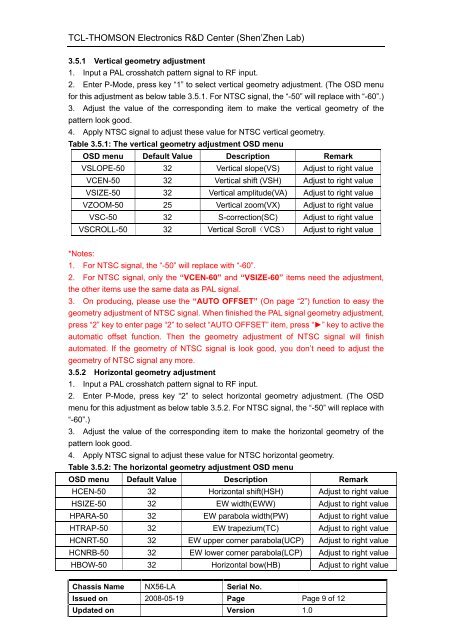
3.5.1 Vertical geometry adjustment<br />
1. Input a PAL crosshatch pattern signal to RF input.<br />
2. Enter P-Mode, press key “1” to select vertical geometry adjustment. (The OSD menu<br />
for this adjustment as below table 3.5.1. For NTSC signal, the “-50” will replace with “-60”.)<br />
3. Adjust the value of the corresponding item to make the vertical geometry of the<br />
pattern look good.<br />
4. Apply NTSC signal to adjust these value for NTSC vertical geometry.<br />
Table 3.5.1: The vertical geometry adjustment OSD menu<br />
OSD menu Default Value Description Remark<br />
VSLOPE-50 32 Vertical slope(VS) Adjust to right value<br />
VCEN-50 32 Vertical shift (VSH) Adjust to right value<br />
VSIZE-50 32 Vertical amplitude(VA) Adjust to right value<br />
VZOOM-50 25 Vertical zoom(VX) Adjust to right value<br />
VSC-50 32 S-correction(SC) Adjust to right value<br />
VSCROLL-50 32 Vertical Scroll(VCS) Adjust to right value<br />
*Notes:<br />
1. For NTSC signal, the “-50” will replace with “-60”.<br />
2. For NTSC signal, only the “VCEN-60” and “VSIZE-60” items need the adjustment,<br />
the other items use the same data as PAL signal.<br />
3. On producing, please use the “AUTO OFFSET” (On page “2”) function to easy the<br />
geometry adjustment of NTSC signal. When finished the PAL signal geometry adjustment,<br />
press “2” key to enter page “2” to select “AUTO OFFSET” item, press “►” key to active the<br />
automatic offset function. Then the geometry adjustment of NTSC signal will finish<br />
automated. If the geometry of NTSC signal is look good, you don’t need to adjust the<br />
geometry of NTSC signal any more.<br />
3.5.2 Horizontal geometry adjustment<br />
1. Input a PAL crosshatch pattern signal to RF input.<br />
2. Enter P-Mode, press key “2” to select horizontal geometry adjustment. (The OSD<br />
menu for this adjustment as below table 3.5.2. For NTSC signal, the “-50” will replace with<br />
“-60”.)<br />
3. Adjust the value of the corresponding item to make the horizontal geometry of the<br />
pattern look good.<br />
4. Apply NTSC signal to adjust these value for NTSC horizontal geometry.<br />
Table 3.5.2: The horizontal geometry adjustment OSD menu<br />
OSD menu Default Value Description Remark<br />
HCEN-50 32 Horizontal shift(HSH) Adjust to right value<br />
HSIZE-50 32 EW width(EWW) Adjust to right value<br />
HPARA-50 32 EW parabola width(PW) Adjust to right value<br />
HTRAP-50 32 EW trapezium(TC) Adjust to right value<br />
HCNRT-50 32 EW upper corner parabola(UCP) Adjust to right value<br />
HCNRB-50 32 EW lower corner parabola(LCP) Adjust to right value<br />
HBOW-50 32 Horizontal bow(HB) Adjust to right value<br />
Chassis Name NX56-LA Serial No.<br />
Issued on 2008-05-19 Page Page 9 of 12<br />
Updated on Version 1.0