Minuet 350 - Antec
Minuet 350 - Antec
Minuet 350 - Antec

You also want an ePaper? Increase the reach of your titles
YUMPU automatically turns print PDFs into web optimized ePapers that Google loves.
<strong>Minuet</strong> <strong>350</strong><br />
User’s Manual<br />
Manuel de l’utilisateur<br />
Anwenderhandbuch<br />
Manuale per l’operatore<br />
Manual del usuario
At <strong>Antec</strong>, we continually refine and improve our products to ensure the highest<br />
quality. As such, your new product may differ slightly from the description in this<br />
manual. This isn’t a problem; it’s simply an improvement. As of the date of publication,<br />
all features, descriptions, and illustrations in this manual are correct.<br />
Disclaimer<br />
This manual is intended only as a guide for <strong>Antec</strong>’s Computer Enclosures. For more<br />
comprehensive instructions on installing the motherboard and peripherals, please<br />
refer to the user manuals that come with those components and drives.<br />
MINUET <strong>350</strong> USER’S MANUAL<br />
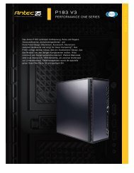
The <strong>Minuet</strong> <strong>350</strong> is a small case that’s big on features. It can be configured in<br />
a desktop or vertical orientation. It comes with an 80PLUS® certified <strong>350</strong> Watt<br />
power supply (PSU). The PSU generates less heat because it is designed for high<br />
efficiency. This keeps the power supply cool and prolongs its working life.<br />
The PSU includes Universal Input with Active Power Factor Correction (PFC).<br />
Universal Input allows you to connect your PSU to any AC power outlet between<br />
100~240V without setting a voltage switch. Active PFC reduces electrical waste<br />
by improving the power factor value to the power supply, helping the power plant<br />
to provide power more efficiently.<br />
The PSU comes with an on/off switch. Make sure you turn the switch to the ON<br />
(I) position before you boot up your computer for the first time. Normally, you<br />
won’t need to switch it OFF (O), since the power supply can be controlled with the<br />
soft on/off switch on the front of your computer case. If your computer crashes<br />
and you can’t shut it down using the soft switch, you can switch the main power<br />
to the OFF (O) position to clear the fault, then reboot.<br />
SETTING UP<br />
1. Take the case out of the box. Remove the Styrofoam and the plastic bag.<br />
Place the case on a flat surface.<br />
2. Remove the thumbscrews from the top panel (at the rear of the case). Slide<br />
the panel to the rear of the case and remove it. Set the panel safely aside.<br />
Note: Please don’t try to use your fingernails to pry or lift the panel.<br />
3. Inside the case you should see the power supply, some wiring with marked<br />
connectors (USB, PWR etc.), an installed I/O panel and a power cord. You will<br />
also find a bag of screws, four rubber feet and two plastic stands.<br />
4. Horizontal Orientation: stick the four adhesive rubber feet to the bottom panel<br />
of the case to protect the paint from scratches.<br />
5. Vertical Orientation: place the <strong>Minuet</strong> <strong>350</strong> in the two plastic stands such that<br />
the side panel with the 80mm fan is facing up. Adjust the stands to fit snugly<br />
against the case sides.<br />
1
Although care has been taken to prevent sharp edges in your <strong>Antec</strong> case, we<br />
strongly recommend taking the appropriate time and caution when working with it.<br />
Please take reasonable precautions.<br />
MOTHERBOARD INSTALLATION<br />
This manual does not cover CPU, RAM, or expansion card installation. Please consult<br />
your motherboard manual for specific mounting instructions and troubleshooting.<br />
1. Lay the case down so that the open side is up. You should be able to see the<br />
drive cage and power supply.<br />
2. Make sure you have the appropriate I/O panel for the motherboard. If the panel<br />
provided is not suitable for the motherboard, please contact the motherboard<br />
manufacturer for the correct I/O panel.<br />
3. Line up the motherboard with the standoff holes. Determine which holes line<br />
up and remember where they are. Not all motherboards will match with all of<br />
the provided screw holes, and this is not necessary for proper functionality.<br />
Some standoffs may be pre-installed for your convenience.<br />
4. Remove the motherboard by lifting it up.<br />
5. Screw in the brass standoffs to the threaded holes that line up with the<br />
motherboard.<br />
6. Place the motherboard on the standoffs.<br />
7. Screw in the motherboard to the standoffs with the provided Phillips-head<br />
screws.<br />
8. The motherboard is now installed.<br />
POWER/LED CONNECTIONS<br />
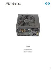
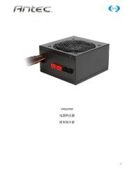
The power supply is an ATX12V form factor power supply. It has a single 24-pin<br />
Main Power Connector, and a 4-pin +12V Power Connector for the motherboard.<br />
It is backwards compatible to previous ATX form factor power supplies. If your<br />
motherboard does not support the +12V 4-pin Power Connector, you can still use<br />
this power supply. It also comes with three 4-pin Peripheral Power Connectors,<br />
one SATA Power Connector and one 4-pin Floppy Drive Power Connector for your<br />
drives.<br />
1. Connect the 24-pin Main Power Connector and<br />
the 4-pin 12V connector to the motherboard<br />
as needed. If the motherboard uses a 20-pin<br />
connector, detach the 4-pin attachment on the<br />
24-pin power connector (see pictures 1 and 2).<br />
Note: the detachable 4-pin section cannot be<br />
used in place of a 4-pin +12V connector.<br />
Picture 1<br />
For 24-pin<br />
motherboards<br />
Picture 2<br />
For 20-pin<br />
motherboards<br />
2. Power Switch (labeled POWER SW) connects to the PWR connector on the<br />
motherboard. Polarity (positive and negative) does not matter for switches.<br />
3. Connect the Power LED (labeled POWER LED) to your motherboard. For LEDs,<br />
colored wires are positive (+). White or black wires are negative (–). If the<br />
LED does not light up when the system is powered on, try reversing the<br />
connection. For more info on connecting LEDs to your motherboard, see your<br />
motherboard manual.<br />
4. Hard Drive LED (labeled HDD LED) connects to the hard drive activity header.<br />
ADD-IN CARDS<br />
Make sure that any cards you add to your <strong>Minuet</strong> <strong>350</strong> case are of the “Low-Profile”<br />
variety. Your <strong>Minuet</strong> is a small form factor case and full-height cards will not fit.<br />
2
CONNECTING THE USB PORTS<br />
You will find a single 10-pin connector on a cable attached to the front USB ports.<br />
This Intel standard connector is keyed so that it can’t be accidentally reversed as<br />
long as it is connected to a proper Intel standard motherboard header. Connect the<br />
10-pin connector to your motherboard headers so that the blocked pin fits over the<br />
missing header pin.<br />
Motherboard USB Pin Layout<br />
1 2<br />
9<br />
10<br />
Pin Signal Names Pin Signal Names<br />
1 USB Power 1 2 USB Power 2<br />
3 Negative Signal 1 4 Negative Signal 2<br />
5 Positive Signal 1 6 Positive Signal 2<br />
7 Ground 1 8 Ground 2<br />
9 Key (No Connection) 10 Empty Pin<br />
Note: Please check your motherboard manual for your USB header pin layout and<br />
make sure it matches the table.<br />
CONNECTING THE eSATA PORT<br />
This case comes with an eSATA port in the front of the case to connect to your<br />
external SATA devices. You will find a SATA connector on a cable attached to the<br />
front eSATA ports. Connect it to a SATA connector on your motherboard.<br />
CONNECTING THE AUDIO PORTS (AC’97 and HDA)<br />
There is an Intel standard 10-pin AC’97 connector and an Intel 10-pin HDA (High<br />
Definition Audio) connector. You can connect either of them to your motherboard<br />
depending on the specification of the motherboard. See instruction below:<br />
Note: Please check your motherboard manual for your audio header pin layout and<br />
make sure it matches the table below. Even if your system supports both audio<br />
standards, you may only connect one connector not both.<br />
Pin Assignment for Audio Ports (HDA and AC’97)<br />
10 6 4 2<br />
9 7 5 3 1<br />
Pin<br />
Signal Names<br />
(HDA)<br />
Pin<br />
Signal Names<br />
(AC’97)<br />
1 MIC2 L 1 MIC In<br />
2 AGND 2 GND<br />
3 MIC2 R 3 MIC Power<br />
4 AVCC 4 NC<br />
5 FRO-R 5 Line Out (R)<br />
6 MIC2_JD 6 Line Out (R)<br />
7 F_IO_SEN 7 NC<br />
8 Key (no pin) 8 Key (no pin)<br />
9 FRO-L 9 Line Out (L)<br />
10 LINE2_JD 10 Line Out (L)<br />
3
DRIVE INSTALLATION<br />
<strong>Minuet</strong> <strong>350</strong> incorporates a rapid-release Flip Up Drive Cage for easy drive<br />
installation. The Cage includes three drive bays: one external 5.25”, one external<br />
3.5”, and one internal 3.5”.<br />
1. Before installing the external drives, remove the external<br />
drive bay covers.<br />
a. To remove the external 5.25” drive bay cover, face the<br />
front of the case and use your left hand thumb to press<br />
firmly on the LEFT or outside edge of the left bay cover<br />
to release it. (See picture 3)<br />
b. To remove the external 3.5” drive bay cover, face the<br />
front of the case and use your right hand thumb to<br />
press firmly on the RIGHT or outside edge of the right<br />
bay cover to release it. (See picture 4)<br />
2. Lift up and slide the drive cage from the case.<br />
3. Place the cage upside down on a flat surface.<br />
Note: You must install the external devices first, before<br />
installing the internal 3.5” device.<br />
4. Slide the external 5.25” device into the drive cage from<br />
the front. Since the drive cage is upside down, your drive<br />
should be too so that it will be properly orientated once the<br />
cage is installed in the <strong>Minuet</strong> <strong>350</strong>.<br />
5. Align the bottom rear screw holes (one at each side) on the<br />
device with the two screw holes (the pair closest to the<br />
front of the cage) on the cage and fasten the device with<br />
the screws provided. (See picture 5)<br />
6. Slide the external 3.5” device into the drive cage from<br />
the front. Since the drive cage is upside down, your drive<br />
should be too so that it will be properly orientated once the<br />
cage is installed in the <strong>Minuet</strong> <strong>350</strong>.<br />
7. Align the bottom rear screw holes (one at each side) on the<br />
device with the two screw holes on the cage and fasten the<br />
device with the screws provided. (See picture 6)<br />
8. To install the internal 3.5” device, find the two mounting<br />
prongs on one side of the bay. With one hand holding the<br />
device at a 45-degree angle with the bottom side up, align<br />
the two screw holes on one side of the device with the<br />
prongs and slide the device into the bay. (See picture 7)<br />
9. Fasten the other side of the device to the two tabs with the<br />
screws provided. (See picture 8.)<br />
10. When sliding the Cage back into the case, work slowly and<br />
carefully to ensure that the front panels of the external devices<br />
align properly with the holes provided for them in the<br />
bezel.<br />
11. Connect power to each of the devices.<br />
Picture 3<br />
Picture 4<br />
Picture 5<br />
Picture 6<br />
Picture 7<br />
Picture 8<br />
4
COOLING SYSTEM<br />
The Side 80mm TriCool fan:<br />
This case comes with one 80mm TriCool side fan installed. This fan has a three-speed<br />
switch that lets you choose the speed that best suits your needs. The default<br />
setting is Low. See the following specifications.<br />
Specifications:<br />
Size:<br />
80 x 80 x 25.4mm<br />
Rated Voltage:<br />
12V<br />
Operating Voltage: 10.2V ~ 13.8V<br />
Speed<br />
High<br />
2600 RPM<br />
Input<br />
Current<br />
0.2A<br />
(Max.)<br />
Air Flow<br />
0.96 m³ / min<br />
(34 CFM)<br />
Medium<br />
2000 RPM 0.15A 0.74 m³ / min<br />
(26 CFM)<br />
Low<br />
1500 RPM<br />
0.1A<br />
0.55 m³ / min<br />
(20 CFM)<br />
Static Pressure<br />
3.04 mm-H2O<br />
(0.12 inch-H2O)<br />
1.79 mm-H2O<br />
(0.07 inch-H2O)<br />
1.00 mm-H2O<br />
(0.03inch-H2O)<br />
Acoustical<br />
Noise<br />
Input<br />
Power<br />
30 dBA 2.4W<br />
24 dBA 1.8W<br />
18 dBA 1.2W<br />
Ventilation<br />
Top Panel:<br />
<strong>Minuet</strong> <strong>350</strong> comes with a vented top panel for maximum cooling capacity. It will<br />
help the airflow inside the case maximizing ventilation and cooling.<br />
Rear Panel:<br />
<strong>Minuet</strong> <strong>350</strong> comes with vents above the I/O panel.<br />
Note: Do NOT install exhausts fans over these vents as they are designed to<br />
take in fresh air to help cool the CPU.<br />
5
<strong>Antec</strong>, Inc.<br />
47900 Fremont Blvd.<br />
Fremont, CA 94538<br />
USA<br />
tel: 510-770-1200<br />
fax: 510-770-1288<br />
<strong>Antec</strong> Europe B.V.<br />
Stuttgartstraat 12<br />
3047 AS Rotterdam<br />
The Netherlands<br />
tel: +31 (0) 10 462-2060<br />
fax: +31 (0) 10 437-1752<br />
Customer Support:<br />
US & Canada<br />
1-800-22ANTEC<br />
customersupport@antec.com<br />
Europe<br />
+31 (0) 10 462-2060<br />
europe.techsupport@antec.com<br />
www.antec.com<br />
© Copyright 2007 <strong>Antec</strong>, Inc. All rights reserved.<br />
All trademarks are the property of their respective owners.<br />
Reproduction in whole or in part without written permission is prohibited.<br />
Printed in China.<br />
34