Minuet 350 - Antec
Minuet 350 - Antec
Minuet 350 - Antec

You also want an ePaper? Increase the reach of your titles
YUMPU automatically turns print PDFs into web optimized ePapers that Google loves.
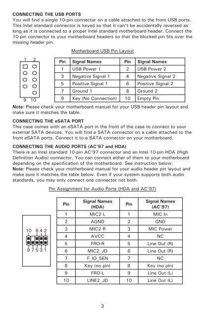
CONNECTING THE USB PORTS<br />
You will find a single 10-pin connector on a cable attached to the front USB ports.<br />
This Intel standard connector is keyed so that it can’t be accidentally reversed as<br />
long as it is connected to a proper Intel standard motherboard header. Connect the<br />
10-pin connector to your motherboard headers so that the blocked pin fits over the<br />
missing header pin.<br />
Motherboard USB Pin Layout<br />
1 2<br />
9<br />
10<br />
Pin Signal Names Pin Signal Names<br />
1 USB Power 1 2 USB Power 2<br />
3 Negative Signal 1 4 Negative Signal 2<br />
5 Positive Signal 1 6 Positive Signal 2<br />
7 Ground 1 8 Ground 2<br />
9 Key (No Connection) 10 Empty Pin<br />
Note: Please check your motherboard manual for your USB header pin layout and<br />
make sure it matches the table.<br />
CONNECTING THE eSATA PORT<br />
This case comes with an eSATA port in the front of the case to connect to your<br />
external SATA devices. You will find a SATA connector on a cable attached to the<br />
front eSATA ports. Connect it to a SATA connector on your motherboard.<br />
CONNECTING THE AUDIO PORTS (AC’97 and HDA)<br />
There is an Intel standard 10-pin AC’97 connector and an Intel 10-pin HDA (High<br />
Definition Audio) connector. You can connect either of them to your motherboard<br />
depending on the specification of the motherboard. See instruction below:<br />
Note: Please check your motherboard manual for your audio header pin layout and<br />
make sure it matches the table below. Even if your system supports both audio<br />
standards, you may only connect one connector not both.<br />
Pin Assignment for Audio Ports (HDA and AC’97)<br />
10 6 4 2<br />
9 7 5 3 1<br />
Pin<br />
Signal Names<br />
(HDA)<br />
Pin<br />
Signal Names<br />
(AC’97)<br />
1 MIC2 L 1 MIC In<br />
2 AGND 2 GND<br />
3 MIC2 R 3 MIC Power<br />
4 AVCC 4 NC<br />
5 FRO-R 5 Line Out (R)<br />
6 MIC2_JD 6 Line Out (R)<br />
7 F_IO_SEN 7 NC<br />
8 Key (no pin) 8 Key (no pin)<br />
9 FRO-L 9 Line Out (L)<br />
10 LINE2_JD 10 Line Out (L)<br />
3