Minuet 350 - Antec
Minuet 350 - Antec
Minuet 350 - Antec

Create successful ePaper yourself
Turn your PDF publications into a flip-book with our unique Google optimized e-Paper software.
Although care has been taken to prevent sharp edges in your <strong>Antec</strong> case, we<br />
strongly recommend taking the appropriate time and caution when working with it.<br />
Please take reasonable precautions.<br />
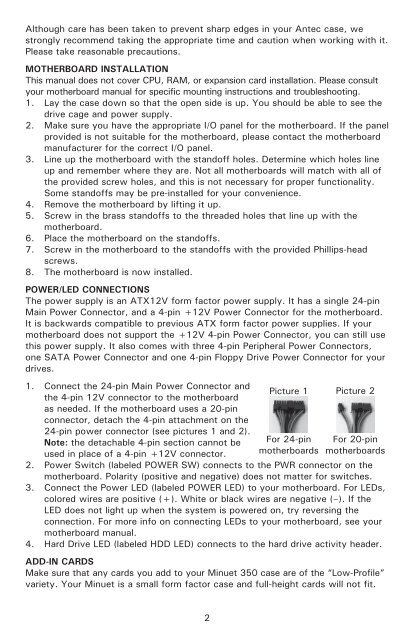
MOTHERBOARD INSTALLATION<br />
This manual does not cover CPU, RAM, or expansion card installation. Please consult<br />
your motherboard manual for specific mounting instructions and troubleshooting.<br />
1. Lay the case down so that the open side is up. You should be able to see the<br />
drive cage and power supply.<br />
2. Make sure you have the appropriate I/O panel for the motherboard. If the panel<br />
provided is not suitable for the motherboard, please contact the motherboard<br />
manufacturer for the correct I/O panel.<br />
3. Line up the motherboard with the standoff holes. Determine which holes line<br />
up and remember where they are. Not all motherboards will match with all of<br />
the provided screw holes, and this is not necessary for proper functionality.<br />
Some standoffs may be pre-installed for your convenience.<br />
4. Remove the motherboard by lifting it up.<br />
5. Screw in the brass standoffs to the threaded holes that line up with the<br />
motherboard.<br />
6. Place the motherboard on the standoffs.<br />
7. Screw in the motherboard to the standoffs with the provided Phillips-head<br />
screws.<br />
8. The motherboard is now installed.<br />
POWER/LED CONNECTIONS<br />
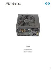
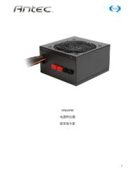
The power supply is an ATX12V form factor power supply. It has a single 24-pin<br />
Main Power Connector, and a 4-pin +12V Power Connector for the motherboard.<br />
It is backwards compatible to previous ATX form factor power supplies. If your<br />
motherboard does not support the +12V 4-pin Power Connector, you can still use<br />
this power supply. It also comes with three 4-pin Peripheral Power Connectors,<br />
one SATA Power Connector and one 4-pin Floppy Drive Power Connector for your<br />
drives.<br />
1. Connect the 24-pin Main Power Connector and<br />
the 4-pin 12V connector to the motherboard<br />
as needed. If the motherboard uses a 20-pin<br />
connector, detach the 4-pin attachment on the<br />
24-pin power connector (see pictures 1 and 2).<br />
Note: the detachable 4-pin section cannot be<br />
used in place of a 4-pin +12V connector.<br />
Picture 1<br />
For 24-pin<br />
motherboards<br />
Picture 2<br />
For 20-pin<br />
motherboards<br />
2. Power Switch (labeled POWER SW) connects to the PWR connector on the<br />
motherboard. Polarity (positive and negative) does not matter for switches.<br />
3. Connect the Power LED (labeled POWER LED) to your motherboard. For LEDs,<br />
colored wires are positive (+). White or black wires are negative (–). If the<br />
LED does not light up when the system is powered on, try reversing the<br />
connection. For more info on connecting LEDs to your motherboard, see your<br />
motherboard manual.<br />
4. Hard Drive LED (labeled HDD LED) connects to the hard drive activity header.<br />
ADD-IN CARDS<br />
Make sure that any cards you add to your <strong>Minuet</strong> <strong>350</strong> case are of the “Low-Profile”<br />
variety. Your <strong>Minuet</strong> is a small form factor case and full-height cards will not fit.<br />
2