A Comprehensive Study of Dilute Magnetic ... - OPUS Würzburg
A Comprehensive Study of Dilute Magnetic ... - OPUS Würzburg
A Comprehensive Study of Dilute Magnetic ... - OPUS Würzburg

Create successful ePaper yourself
Turn your PDF publications into a flip-book with our unique Google optimized e-Paper software.
64 5. A voltage controlled spin-valve<br />
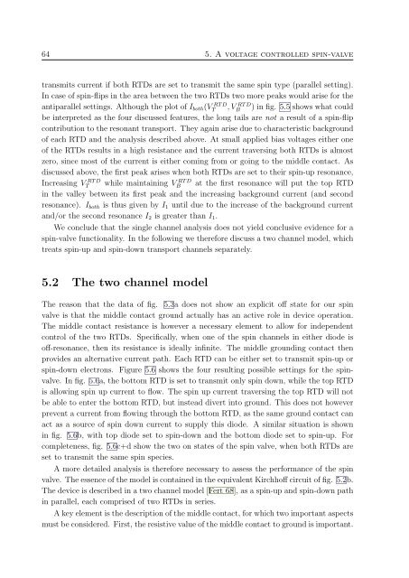
transmits current if both RTDs are set to transmit the same spin type (parallel setting).<br />
In case <strong>of</strong> spin-flips in the area between the two RTDs two more peaks would arise for the<br />
antiparallel settings. Although the plot <strong>of</strong> I both (VT<br />
RT D , VB<br />
RT D ) in fig. 5.5 shows what could<br />
be interpreted as the four discussed features, the long tails are not a result <strong>of</strong> a spin-flip<br />
contribution to the resonant transport. They again arise due to characteristic background<br />
<strong>of</strong> each RTD and the analysis described above. At small applied bias voltages either one<br />
<strong>of</strong> the RTDs results in a high resistance and the current traversing both RTDs is almost<br />
zero, since most <strong>of</strong> the current is either coming from or going to the middle contact. As<br />
discussed above, the first peak arises when both RTDs are set to their spin-up resonance,<br />
Increasing VT<br />
RT D while maintaining VB<br />
RT D at the first resonance will put the top RTD<br />
in the valley between its first peak and the increasing background current (and second<br />
resonance). I both is thus given by I 1 until due to the increase <strong>of</strong> the background current<br />
and/or the second resonance I 2 is greater than I 1 .<br />
We conclude that the single channel analysis does not yield conclusive evidence for a<br />
spin-valve functionality. In the following we therefore discuss a two channel model, which<br />
treats spin-up and spin-down transport channels separately.<br />
5.2 The two channel model<br />
The reason that the data <strong>of</strong> fig. 5.3a does not show an explicit <strong>of</strong>f state for our spin<br />
valve is that the middle contact ground actually has an active role in device operation.<br />
The middle contact resistance is however a necessary element to allow for independent<br />
control <strong>of</strong> the two RTDs. Specifically, when one <strong>of</strong> the spin channels in either diode is<br />
<strong>of</strong>f-resonance, then its resistance is ideally infinite. The middle grounding contact then<br />
provides an alternative current path. Each RTD can be either set to transmit spin-up or<br />
spin-down electrons. Figure 5.6 shows the four resulting possible settings for the spinvalve.<br />
In fig. 5.6a, the bottom RTD is set to transmit only spin down, while the top RTD<br />
is allowing spin up current to flow. The spin up current traversing the top RTD will not<br />
be able to enter the bottom RTD, but instead divert into ground. This does not however<br />
prevent a current from flowing through the bottom RTD, as the same ground contact can<br />
act as a source <strong>of</strong> spin down current to supply this diode. A similar situation is shown<br />
in fig. 5.6b, with top diode set to spin-down and the bottom diode set to spin-up. For<br />
completeness, fig. 5.6c+d show the two on states <strong>of</strong> the spin valve, when both RTDs are<br />
set to transmit the same spin species.<br />
A more detailed analysis is therefore necessary to assess the performance <strong>of</strong> the spin<br />
valve. The essence <strong>of</strong> the model is contained in the equivalent Kirchh<strong>of</strong>f circuit <strong>of</strong> fig. 5.2b.<br />
The device is described in a two channel model [Fert 68], as a spin-up and spin-down path<br />
in parallel, each comprised <strong>of</strong> two RTDs in series.<br />
A key element is the description <strong>of</strong> the middle contact, for which two important aspects<br />
must be considered. First, the resistive value <strong>of</strong> the middle contact to ground is important.