resolver decoder specifications - Steven Engineering
resolver decoder specifications - Steven Engineering
resolver decoder specifications - Steven Engineering

Create successful ePaper yourself
Turn your PDF publications into a flip-book with our unique Google optimized e-Paper software.
INTERFACING ABSOLUTE POSITION<br />
DECODERS TO PLCS AND<br />
MICROCOMPUTERS<br />
Microcomputers and PLCs are sequential logic devices. In<br />
contrast to a real-time hardware logic, which can perform<br />
many operations at the same time, a PLC can perform only a<br />
single operation before proceeding to the next logical step. The<br />
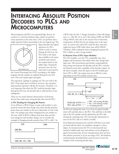
figure describes the logical<br />
operation of a PLC,<br />
which is cyclic in nature.<br />
During the I/O scan, the<br />
PLC looks at the input<br />
data available at the input<br />
terminals and activates<br />
the outputs based on the<br />
ladder logic. During the<br />
processor scan, the new<br />
input data is processed by<br />
the Central Processing Unit (CPU) according to the ladder<br />
program and the outputs are updated during the next I/O<br />
scan. This cycle repeats again and again.<br />
The expression "garbage in, garbage out" fits very well to the<br />
PLC. If the input data is invalid or incorrect, the corresponding<br />
machine operation will also be incorrect. Therefore, it is<br />
very important that when the PLC reads the <strong>decoder</strong> input<br />
during the I/O scan, the <strong>decoder</strong> data is valid and free of any<br />
ambiguities.<br />
There are two main inherent characteristics of electronic<br />
devices that could cause wrong <strong>decoder</strong> data into the PLC:<br />
a) PLC Reading the Changing Bit Pattern:<br />
As we all know, a BCD, binary, or gray code number is composed<br />
of various bits that change state when <strong>decoder</strong> position<br />
passes from one number to the next. Inherently, in Gray Code<br />
only 1 bit changes state when changing from one number to<br />
the next, while in BCD or Binary data more than one bits<br />
may change for each number change. Let us consider the<br />
example of changing <strong>decoder</strong> position from 199° to 200 °. In<br />
a BCD code, for this 1° change of position, 6 bits will change<br />
state, i.e., 100, 80, 10, 8, and 1 bits will go LOW and 200 bit<br />
will go HIGH. And, due to the reaction time of electronic<br />
components, all these bits do not change state at the same<br />
time. At a given time when PLC reads the data, some bits<br />
might have gone LOW while others may still be HIGH.<br />
Therefore, while reading the above changing bit pattern the<br />
PLC is liable to read a wrong number.<br />
b) Reaction Time of PLC Input Modules:<br />
PLC I/O modules, even the TTL compatible ones, have<br />
lengthy and inconsistent time delays when they change their<br />
logic state. This inconsistency gets further compounded by<br />
long wiring runs between the <strong>decoder</strong> and the PLC, and also<br />
the limited current drive capability of the <strong>decoder</strong> outputs. In<br />
the above example, when the input to the I/O module goes<br />
from 199° to 200°, the output may stay at 000 for a time,<br />
depending on the I/O module reaction time.<br />
An I/O scan during this time (2 to 10 ms in typical installations)<br />
will read false data to the PLC. The solid line is the field<br />
side of the I/O module and the dashed line the PLC side.<br />
During the switching time (TS), the <strong>decoder</strong> information as<br />
seen on the PLC side is 0, which is invalid.<br />
Even dedicated microprocessor controls with faster scan times<br />
are faced with the above two problems, though to a lesser<br />
degree. In microprocessors the TS is in microseconds (µs)<br />
instead of milliseconds (ms) and software can be designed to<br />
ignore inconsistent data. If your microprocessor does not have<br />
this software provision or if you are using a PLC, the hardware<br />
synchronization described below must be used to assure the<br />
integrity of the incoming <strong>decoder</strong> data.<br />
SECTION<br />
A<br />
Position Transducers/Sensors<br />
800-TEC-ENGR<br />
www.avg.net<br />
A-19